Article

Comparative Study of Flank Cams Manufactured by WEDM and Milling Processes

by
Irene Buj-Corral
*,†,
Enrique Zayas-Figueras
and
Àngels Montaña-Faiget
Department of Mechanical Engineering, School of Engineering of Barcelona (ETSEIB), Universitat Politècnica de Catalunya (UPC), Av. Diagonal, 647, 08028 Barcelona, Spain
*
Author to whom correspondence should be addressed.
Equal contribution to this paper.
Metals 2020, 10(9), 1159; https://doi.org/10.3390/met10091159
Submission received: 29 July 2020 / Revised: 21 August 2020 / Accepted: 22 August 2020 / Published: 27 August 2020
(This article belongs to the Special Issue State-of-Art within 3D Printing and Advanced Machining Processes)

Abstract

:
Cam-follower mechanisms are usually employed in different machines, like combustion engines, sewing machines, machine tools, etc. In the present paper, the option to manufacture cams utilizing wire electrical discharge machining (WEDM) has been considered. For this, surface roughness and shape error of cam profiles manufactured by the processes of milling and wire electrical discharge machining (WEDM) are presented. The methodology used covers different stages: design, prototyping, manufacturing, and measurement of the cams. As a reference, a cam-follower mechanism from a motorcycle internal combustion engine has been used. A reverse engineering process has been performed to determine the geometrical parameters of the mechanism, which are used for the synthesis of the profile of the cam and its subsequent design. The manufacturing process of the cams has been assisted by CAD-CAM (Computer Assisted Drawing-Computer Assisted Manufacturing) software. Using fused filament fabrication (FFF), a physical prototype of the cam has been manufactured, in order to validate the goodness of the design. Finally, the roughness and shape parameters have been measured on the contour surface of the cams. The arithmetical mean roughness Ra value of the milled cam was 0.269 μm, below the requirement of 0.4 μm, and shape error was 18 μm, below 50 μm. Shape error of the WEDM cam of 48 μm meets the requirements for cams. However, the Ra value of 1.212 μm, exceeded the limit. For this reason, a finish operation is recommended in this case. Some advantages of WEDM cams over milled cams are that different conductive materials can be employed, more complex shapes can be obtained, and that, in rough operations, the amount of material to be removed in subsequent operations is considerably reduced.

1. Introduction

The cam-follower mechanisms have wide applications in different kinds of machines such as alternative combustion engines, sewing machines, machine tools, etc., due to their advantages. For instance, they are simple and compact mechanisms, they are cheap, they have few mobile parts, and the follower displacement law is easy to design. The cam mechanisms have three parts: a cam, a follower, and a fixed frame [1]. The most common cam-follower mechanism that is employed in combustion engines consists of a disk cam and a follower with translating or oscillating movement (Figure 1a). The cams for combustion engines are usually symmetric, while the ones that are used in high speed applications or aeronautics are asymmetric [2]. The cams for combustion engines can be classified into three categories: convex flank cams, tangential flank cams, and concave flank cams. In the present work, a tangential flank cam has been used (Figure 1b).
In the past, the available technologies made it difficult to obtain cams with precise geometries and surface finish. At present, thanks to the numerical control (NC) machines, this phase has been successfully overcome. Today the tedious calculations of the cam design process are assisted by software that allows to obtain the profiles and the graphics in a faster and more precise way [2]. In the 70s of the last century, Grant has analyzed the different methods to manufacture cams [3]. He classified them into three categories: methods for original cams (using conventional machines and manual finish operations), methods for copied cams (using milling machines with indexing heads and/or copying mechanisms, as well as grinding machines), and methods that used numerical control machines. These machines have evolved considerably over time until today, and its use has become widespread in the field of cam manufacturing. On the other hand, for large batches, other manufacturing processes are employed, like forging [4], sintering [5], etc. Wire Electric Discharge Machining (WEDM) consists of using a thin wire of a conductive material like brass, which is wound between two spools, in order to cut a conductive material using electrical discharges. A dielectric fluid such as water allows isolating the wire from the workpiece to achieve a high current density, it cools the heated surface of the wire and it removes the material particles. Due to the high temperatures reached, the surface layer melts and then it quickly cools because of the fluid, leading to the so-called recast layer [6]. Heat can also induce tensile residual stresses, cracks, or microporosity on the parts’ surface [7,8]. Some advantages of WEDM processes are that they allow machining different conductive materials regardless of their hardness [9], for example, titanium alloys used in biomedical applications [10], and that it is appropriate for delicate or fragile materials, because it eliminates the mechanical stresses that are present in traditional machining processes [11]. Besides, complex shapes and thin-walled parts can be obtained, such as noncircular gears, including elliptical and oval gears [12] or inclined surfaces that are used in tooling that requires draft angle [13]. Moreover, WEDM avoids the need to manufacture the pre-shaped electrodes that are necessary for sink electrical discharge machining (SEDM) [14]. In recent years, WEDM has started to replace conventional machining in some rough operations, for example, for the manufacture of blades, with the advantage that the amount of material to be removed in subsequent operations is considerably reduced [15]. The main parameters of the WEDM process are: discharge current, servo voltage, pulse on and off time, and wire feed, among others. Several authors have studied the effect of WEDM parameters on surface roughness. For example, Hegab et al. [16] optimized material removal rate, wear electrode ratio, and average surface roughness Ra as a function of machining on-time, discharge current, voltage, total depth of cut and percentage in weight of carbon nanotube composites (CNT) added to an aluminum base. Sonawane et al. [17] considered WEDM parameters such as pulse-on time, servo voltage, pulse-off time, peak current, feed rate, and cable tension and responses like surface roughness, overcut and material removal rate, in Nimonic-75 alloy. Magabe et al. [18] investigated the effect of spark gap voltage, pulse on-time, pulse off-time, and wire feed on the material removal rate and surface roughness of a Ni-Ti shape memory alloy. Chaudhary et al. [19] considered pulse-on time, pulse-off time, and current as process parameters, whereas material removal rate (MRR), surface roughness, and micro-hardness as responses, in superelastic Nitinol shape memory alloy.
Measurement of the shape error of cams is important because better accuracy of the cam profile obtained will favor the compliance of the follower with the motion-law and, consequently, a better operation of the mechanism. Most authors specify a range of tolerances for the manufacture of a cam by means of geometric tolerances, like the shape error, that is, they define a band along the entire contour that validates the functionality of the piece if the measured points on the contour are within the marked band. For example, Norton stated that shape error of ±25 μm or lower (total error of 50 μm) is appropriate for cams [2]. Kang and Han [20] measured form deviation errors of a disk cam on a profile-measuring machine. They found a total form deviation error of 0.1874 mm. Hsieh and Lin [21] proposed and validated a method to carry out the automatic measurement of a cylindrical cam on a coordinate measuring machine (CMM); the method uses a homogenous transformation matrix to derive the CMM ability function matrix and the measuring probe location matrix. The cam was machined on a four-axis vertical machine tool. The maximum deviation between the experimental and theoretical profiles was 21 μm. Other authors, such as Chang and Wu, specify measurements based on dimensional tolerances [22]. The maximum radial dimension of a cam was set to 19.05 mm in this case. Taking into account IT9 for WEDM and IT7 for CNC machining processes, tolerance amplitude values of 52 μm and 21 μm, respectively, were defined. In another example, Le and Nguyen Tank [23] obtained dimensional tolerances for a milled planar cam (with a maximum dimension of 150 mm) of at least 0.018 mm, corresponding to IT5. Regarding the shape error of WEDM curved surfaces. Werner [24] manufactured internal contours and measured shape errors of the profile with a coordinate measuring machine (CMM). He found deviation values between +0.008 mm and −0.010 mm with respect to the theoretical curves. In a comparative study regarding miniature brass gears manufactured using either WEDM and hobbing [25], it was observed that WEDM gears had higher quality than hobbed gears. Form error found was 5.4 μm for the WEDM gears [26].
As for surface roughness of cams, Islam et al. [27] made a numerical approach based on mixed lubrication concept considering roller sliding to predict the friction, taking into account the friction from cam/roller contact, cam bearings, valve/guide, needle roller bearing, and the effect of asperity interaction and roller sliding. A reduction in friction was obtained with a rise in the camshaft speed. Furthermore, they observed that an increased asperity interaction at high operating temperature yielded to relatively higher friction magnitude, especially in the nose of the cam profile, due to a lower curvature radius. Torabi et al. [28] presented a thermo-elasto-hydrodynamics analysis to study the behavior of the cam-and- follower contact, particularly during the running-in period. Their results have shown that the rate of flattening of surface roughness is a crucial factor influencing thermal effects during the running-in period. Therefore, according to the literature cited here, it is important to control the asperity (surface roughness) in the cam profile. Surface finish also influences the lubrication and aesthetic appearance of the cam. In contacts such as those between cam and follower, high surface roughness can lead to high local pressure and a reduction in the real contact area between cam and follower [29]. For this reason, low roughness is required in this case. Agulló and Cardona [30] stated that, when the unit cost is important, an appropriate surface finish for steel cams would be Ra < 0.4 μm. Traditionally, a grinding operation was necessary in order to achieve such roughness values [2]. In a comparative study for cams, Ra = 1.09 μm were obtained in the outer surface of a milled cam, and Ra = 1.42 μm in a WEDM cam, both made of AA6063 aluminum [31]. In another comparative study between hobbing and WEDM for the manufacture of gears, better surface finish was found for WEDM [26]. The average surface roughness was 1 μm, and maximum surface roughness was 6.4 μm in this case. In another work about gear prototypes, Ra = 0.42 μm was reported for the WEDM parts [32].
Machining processes have traditionally been used to obtain cams. However, other technologies like electric discharge machining could replace conventional cutting processes with important advantages, such as the possibility to use hard materials, the possibility to design more complicated shapes, and the reduction of mechanical stresses. Until now, few works are known about the manufacture of cams using WEDM [31]. The main objective of the present paper is to consider the possibility to manufacture tangential flank cams by means of WEDM, and to compare them with milled cams, in terms of surface finish and shape error of their external contours. The geometry of a cam profile has been designed, taking as reference a real cam from a camshaft of a motorcycle engine. The structure of the paper is as follows: Section 2 describes the methods that are used to manufacture the cams, by means of either milling or WEDM, as well as the way the roughness and shape error measurements were performed. Section 3 shows the results of visual inspection, surface roughness, and shape error of the cams; Section 4 and Section 5 contain the discussion and conclusions, respectively.

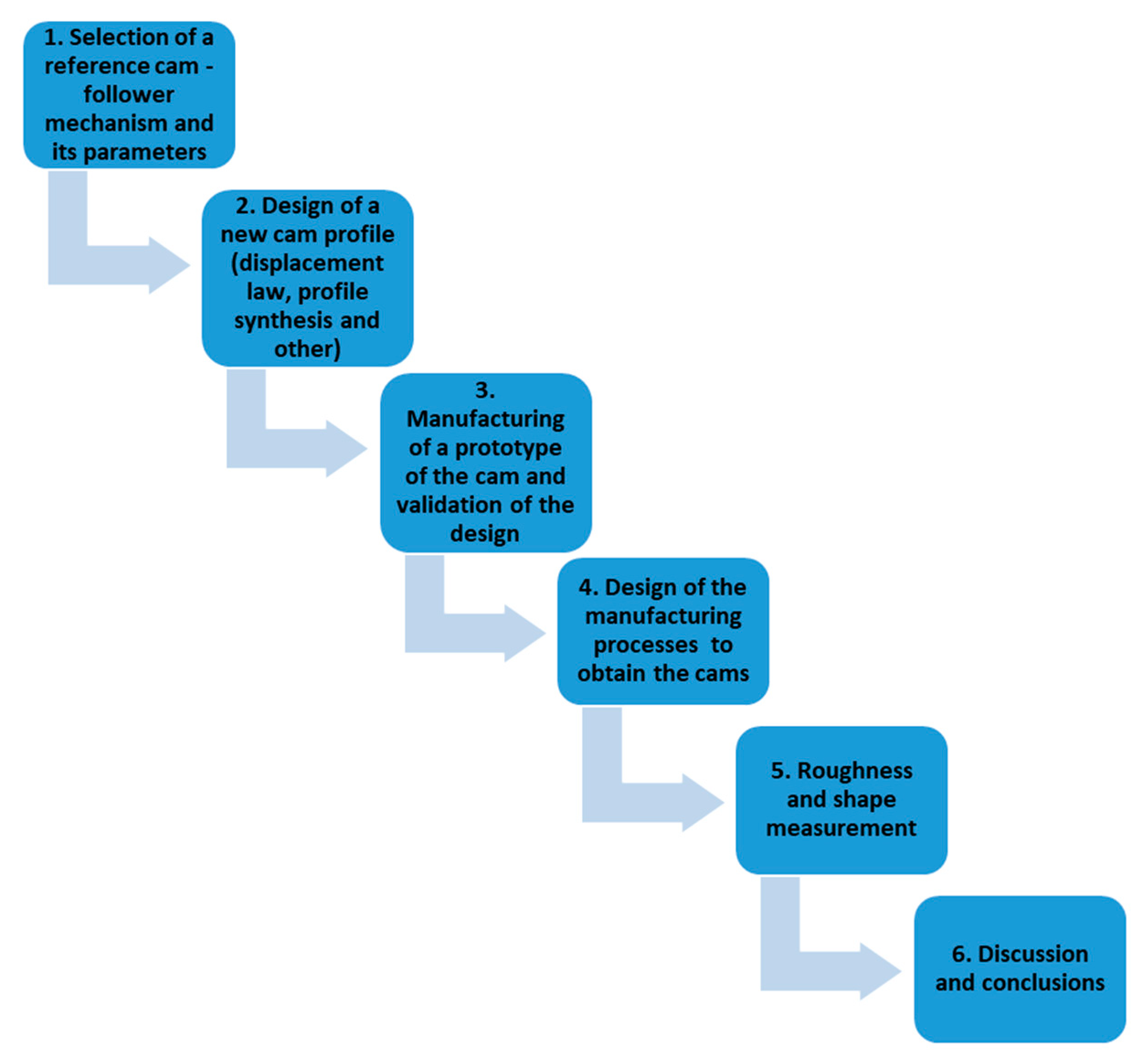
2. Materials and Methods

Figure 2 presents the general methodology of the present work.
The exposed methodology consists of six steps, which will be explained in the following subsections. First, a reference cam-follower mechanism was selected. Then, using reverse engineering, a new cam profile was designed. Next, a three-dimensional (3D) printed prototype was obtained to validate the design. Then, the manufacturing process of the cams, obtained by either milling or WEDM, was defined. The cams were manufactured, and both roughness and shape error of their external contour were measured. Finally, conclusions were drawn from the results.

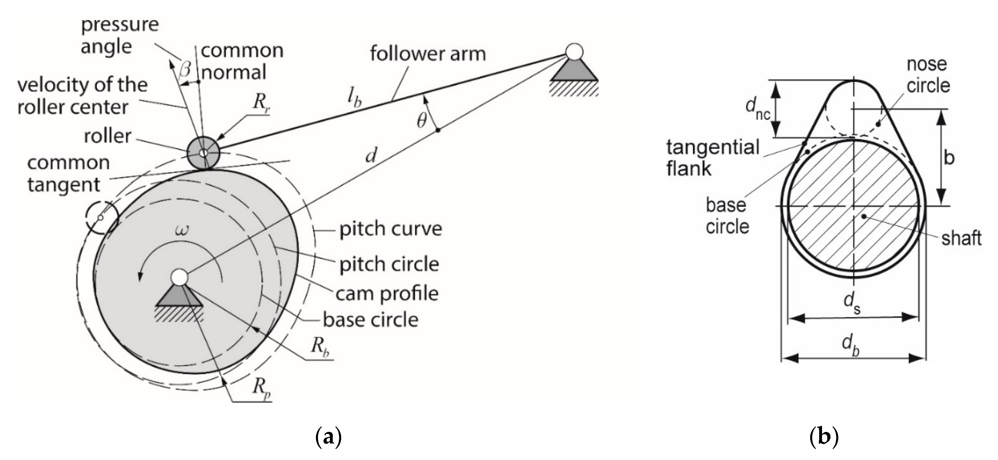
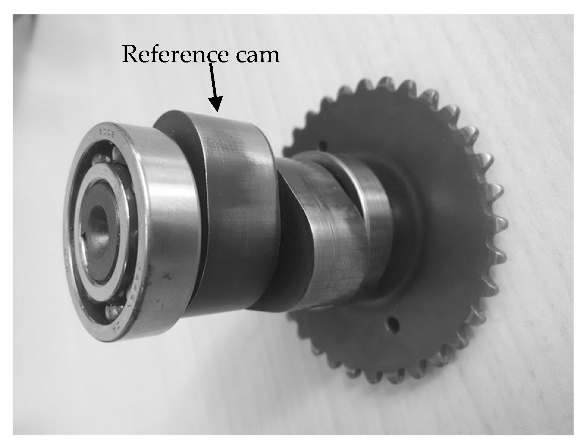
2.1. Selection of a Reference Cam-Follower Mechanism

As a start point, a reference cam-follower mechanism was selected, a real cam from the camshaft of a single-cylinder internal combustion engine of a motorcycle (Figure 3), available at the Department of Mechanical Engineering (DEM) of the School of Engineering of Barcelona (ETSEIB). Because of the absence of geometric data of the reference cam and follower mechanism, as well as about their displacement law, reverse engineering was used to determine the required start information for the design process of the cam. Different parameters of the real cam-follower mechanism were measured (see Figure 4 and Table 1), with a Mitutoyo digital micrometer.
From these parameters, the design process of the mechanism has been carried out, in order to obtain the corresponding cam profile to be manufactured.

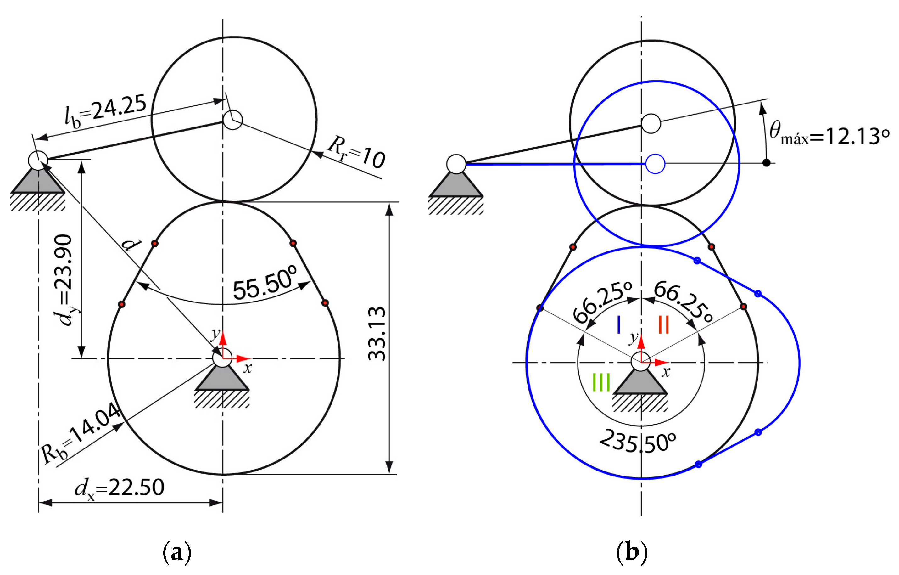
2.2. Design of a New Cam Profile

The design process of a cam-follower mechanism consists of three steps [33]:
(a)
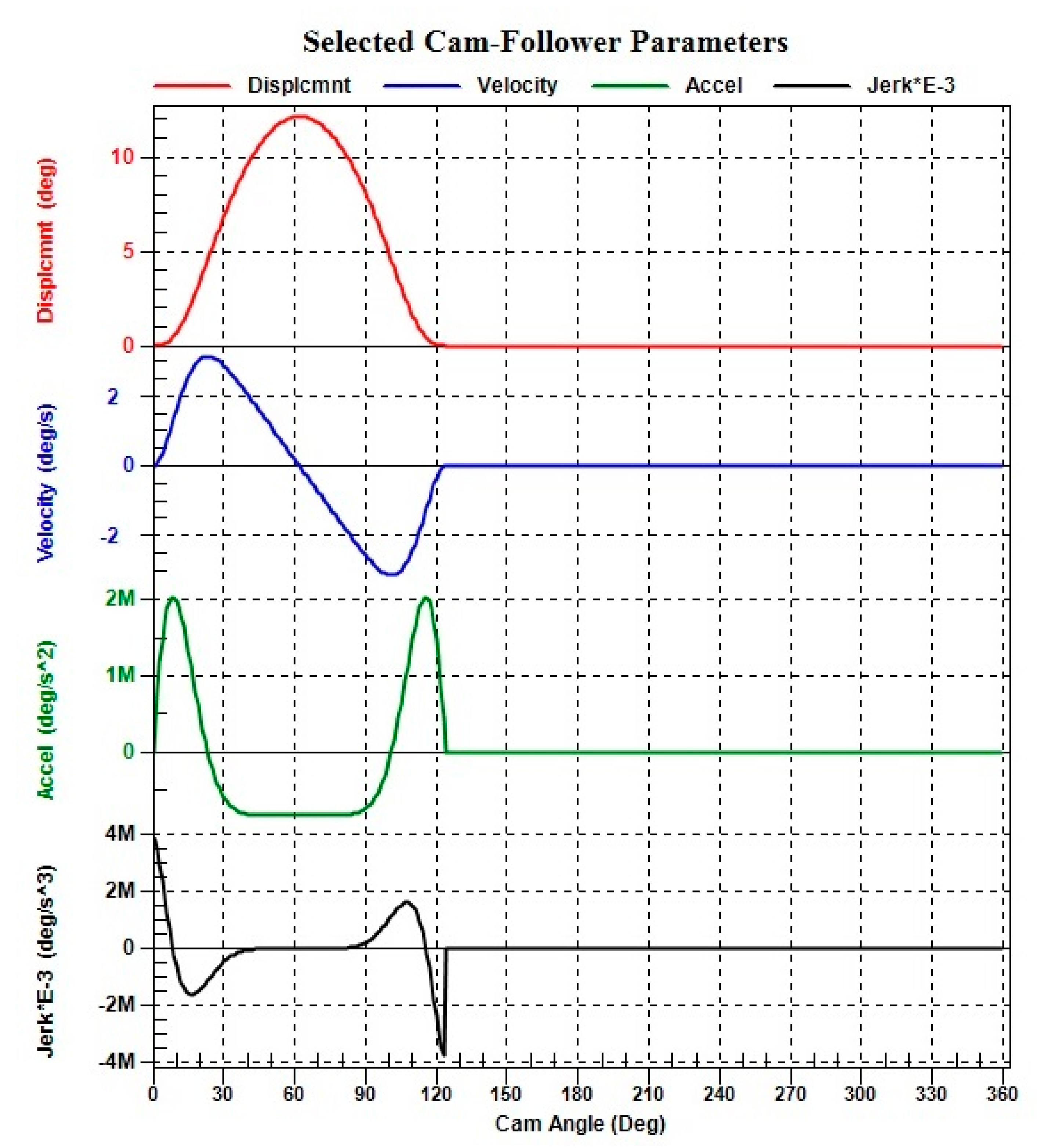
to design the follower displacement law,
(b)
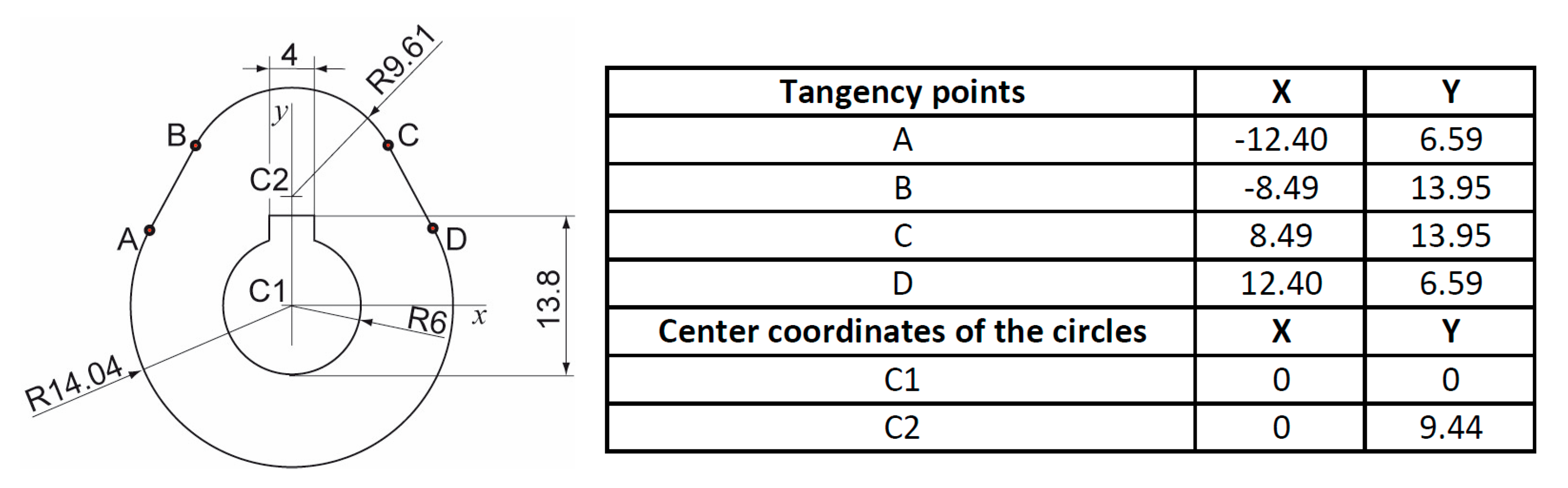
to obtain the cam profile according to the designed displacement law, and
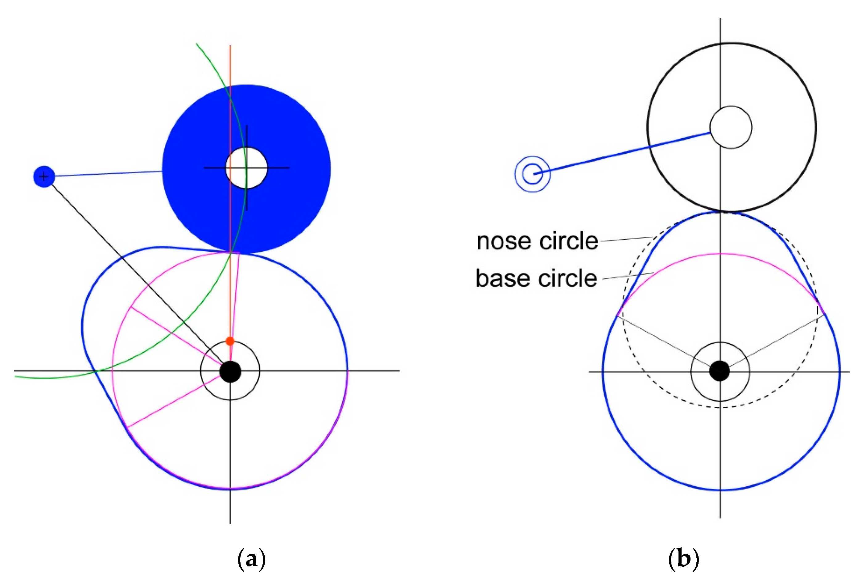
(c)
to check that the curvature of the cam profile guarantees a correct cam-follower contact.
In this work, the Dynacam 9.5.0.153 software (Norton Associates Engineering, Norfolk, MA, US) was used to design the cam [34]. After initial analysis, it was decided to choose the Polydyne function as the movement law of the follower, which is frequently used in the design of camshafts of internal combustion engines and in cams of textile machines [35]. Figure 5 shows the kinematic graphics obtained with the Dynacam software. The analysis of the graphics allows checking the continuity of the movement law until the second derivative [34]. Then, the cam profile has been generated, and it has been checked if the cam curvature was appropriate to ensure good performance (Figure 6).
The two performance quality indices of the mechanism, pressure angle, and cam profile curvature radius, have been checked with Dynacam (Table 2).
The profile of the designed cam consists of two arcs of circles and two small segments that join them. These segments, called flanks, correspond to two circle arcs with a large radius of curvature that, at first glance, appear to be straight sections. These two flanks have been adjusted to two small tangent straight segments with respect to the base circle (larger radius) and the nose circle (smaller radius) to simplify the manufacturing processes. Therefore, a tangential flank cam has been designed (Figure 1b).

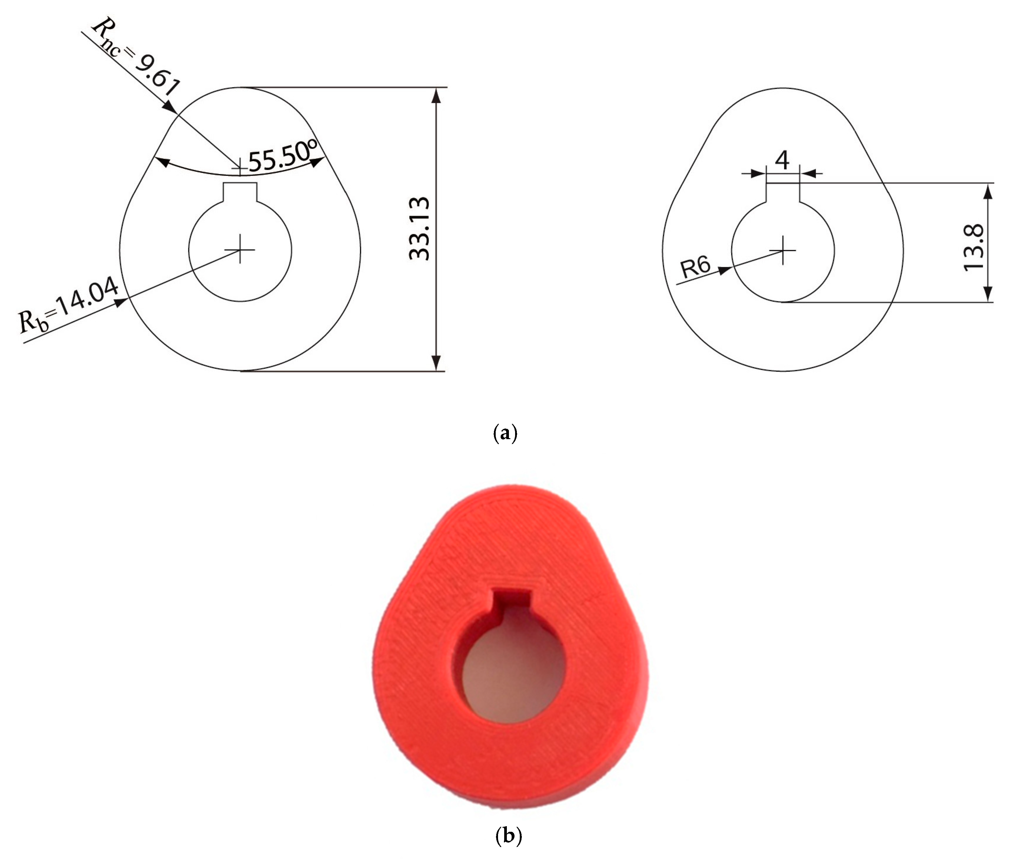
2.3. Manufacturing of a Prototype of the Cam and Validation of the Design

For the 3D design, a thickness value of 13 mm and a hole diameter of 12 mm have been selected, corresponding to the measurements of the model cam. The dimensions of the keyway have been defined according to DIN 6885 [36], which is equivalent to the withdrawn standard ISO R773 [37] (Figure 7a).
Based on the profile obtained, a virtual prototype of the cam has been created using SolidWorks 2016 (Dassault Systèmes SE, Vélizy-Villacoublay, France). Subsequently, a prototype of the cam has been printed in polylactic acid (PLA) with the fused filament fabrication (FFF) or fused deposition modeling (FDM) technology (Figure 7b).
From a visual inspection, it was found that the physical prototype was similar to the model cam, thus validating the goodness of the design.

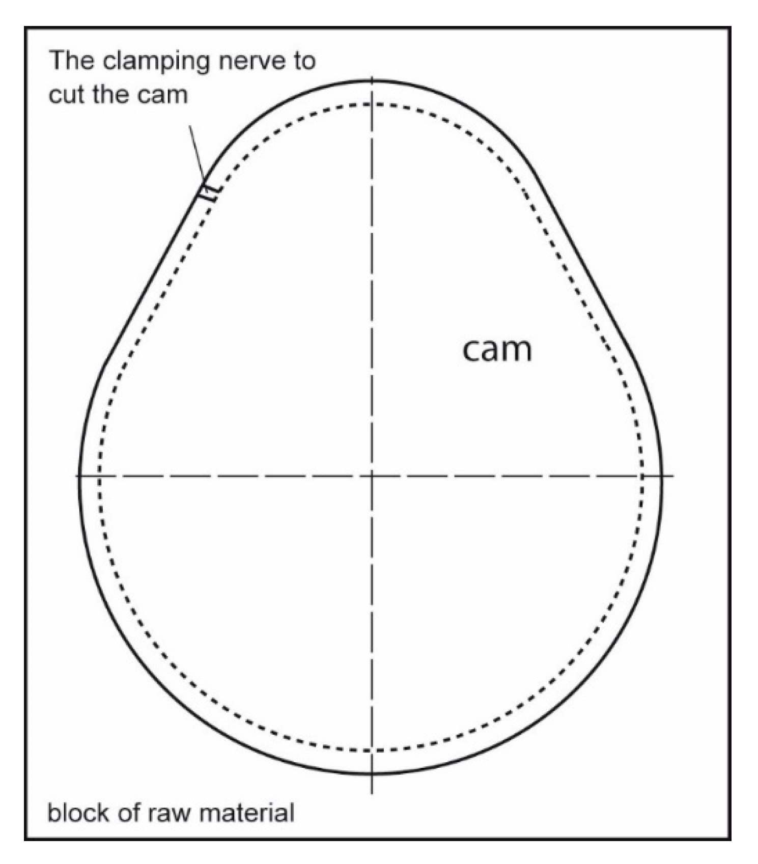
2.4. Design of the Manufacturing Processes to Obtain the Cams

The cams have been manufactured with NC milling and with WEDM, respectively. For both processes, the machines, tools, and fixtures to be used have been defined, as well as the cutting conditions. Table 3 presents the main characteristics of the two processes.
A common high temperature structural steel was used to manufacture the cams, C45E4 from ISO 4957 [38].
Both the milling and the WEDM process are described in more detail in the following subsections.

2.4.1. Machining Process

The CAM (Computer Aided Manufacturing) software Cimatron 11.0 (3D Systems, Rock Hill, SC, USA) has been used to generate the g-code for the machining canter. The raw material was a block of dimensions 50 mm × 50 mm × 22 mm. The software simulates the programmed stages to evaluate possible tool-piece intersections or errors in the trajectory followed by the tool. Two operations were carried out, rough and finish contour milling.

2.4.2. WEDM

Because no simulation software was available for the WEDM process, the tool path of the wire and the contour of the cam have been manually programmed using the assisted programming of the machine. For this, the tangency points of the profile, that is, the points that join the different sections of the cam profile, have been determined, and either circular or linear interpolation has been applied. Before programming, the dimensions of the material, a 50 mm × 50 mm × 16 mm block, were introduced in the program. An excessively high cutting speed value was avoided to prevent the wire from breaking. The wire diameter used was 0.25 mm.
Only rough machining was used, because it was not possible to machine the full shape without reclamping it, which would have induced alignment errors [32].

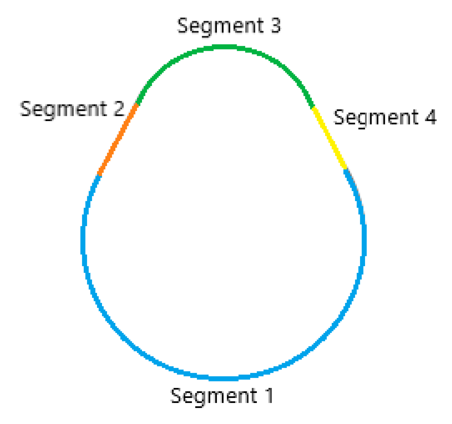
2.5. Roughness and Shape Measurement

2.5.1. Roughness Measurement

The surface finish of the cams has been measured and analyzed with a Taylor Hobson contact roughness meter—Form Talysurf Series 2 model—using a contact inductive sensor with a resolution of 18 nm in a height range of 1 mm.
The cut-off value employed was 0.8 mm, with a measurement length of 4 mm, according to the ISO 4288 standard [39]. One measurement was carried out on each of the four areas of the cam contour (see Section 2.5.2), along the longitudinal direction of the cam. Arithmetical mean height parameter Ra was considered.

2.5.2. Shape Measurement

The cam profile was measured in a Mitutoyo Euro CA5-44 coordinate measuring machine (CMM), with Mcosmos v3.0 software (Mitutoyo Corporation, Kawasaki-shi, Kanagawa, Japan). The shape error is defined as the distance between the highest and the lowest distortion along the complete measured profile.
The coordinate origin (xc1, yc1) was defined at the center of the cam hole, from which the positions (xi, yi, zi,) of the profile points were determined (Figure 8). Later, 354 points of the contour of the piece have been measured at a vertical distance of zi = 5 ± 0.001 mm from the upper face of the cam.
In the measurement process, the cam profile was divided into four segments (Figure 9). Segment 1 corresponds to the base circle (in blue); segment 3 corresponds to the nose circle (in green); and, segments 2 (in orange) and 4 (in yellow), correspond to the straight flanks.
This division of the measured profile in sections might introduce some geometrical errors. In order to minimize them, each tangency area has been measured twice, from the two corresponding adjacent areas, and the measurement having greater error has been discarded.
Next, the procedure used in order to determinate the difference between the measured and the theoretical profiles is explained. From the CAD file, the four geometric entities that constitute the theoretical cam profile have been defined: the base circle, the nose circle, and the two straight flanks. The circles are defined using three parameters: the (xc, yc) coordinates of the cam hole center and its radius Rc. The straight sections have been defined using the A, B, and C parameters, according to the equation of the line Ax + By + C = 0.
On the other hand, the coordinates (xi, yi) of the measured points of the cam profiles have been obtained with the CMM. Subsequently, a transformation (rotation and translation) of the measured points required, in order to make a superposition of the measured and the theoretical profile, so as to minimize the differences between them. This minimization problem is solved with a code written in Matlab R2015b (Mathworks, Natick, MA, US). This code calculates the values of the parameters (x’, y’) of the translation and the angle θ of the rotation that minimizes the distance between the measured points and the theoretical profile, which is, the sum of the point-straight line and point-circle distances (Equation (1)).
( x y ) = [ cos θ sin θ sin θ cos θ ] · ( x i y i ) + ( x 0 y 0 )
The equation of the perpendicular distance between a point—straight line, dpoint-line is (Equation (2)):
d point line = | A x   +   B y   +   C | A 2 + B 2
The equation of the perpendicular distance between a point—circle, dpoint-circle is (Equation (3)):
d point circle = | ( x x c ) 2 + ( y y c ) 2 R c |                                                  
where xc and yc are the coordinates of the center of the circle.
Table 4 shows the values of x’ translation, y’ translation, and rotation θ that must be applied to the measured points in order to minimize the square value of the distance between both of the profiles, which is, the measured error.

3. Results

In the present section, first, the results of a visual inspection are presented, followed by the roughness measurements (micro geometric errors) and the shape measurements (macro geometric errors).

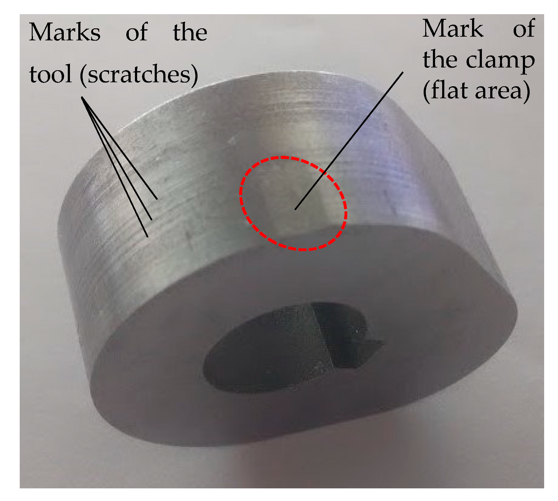
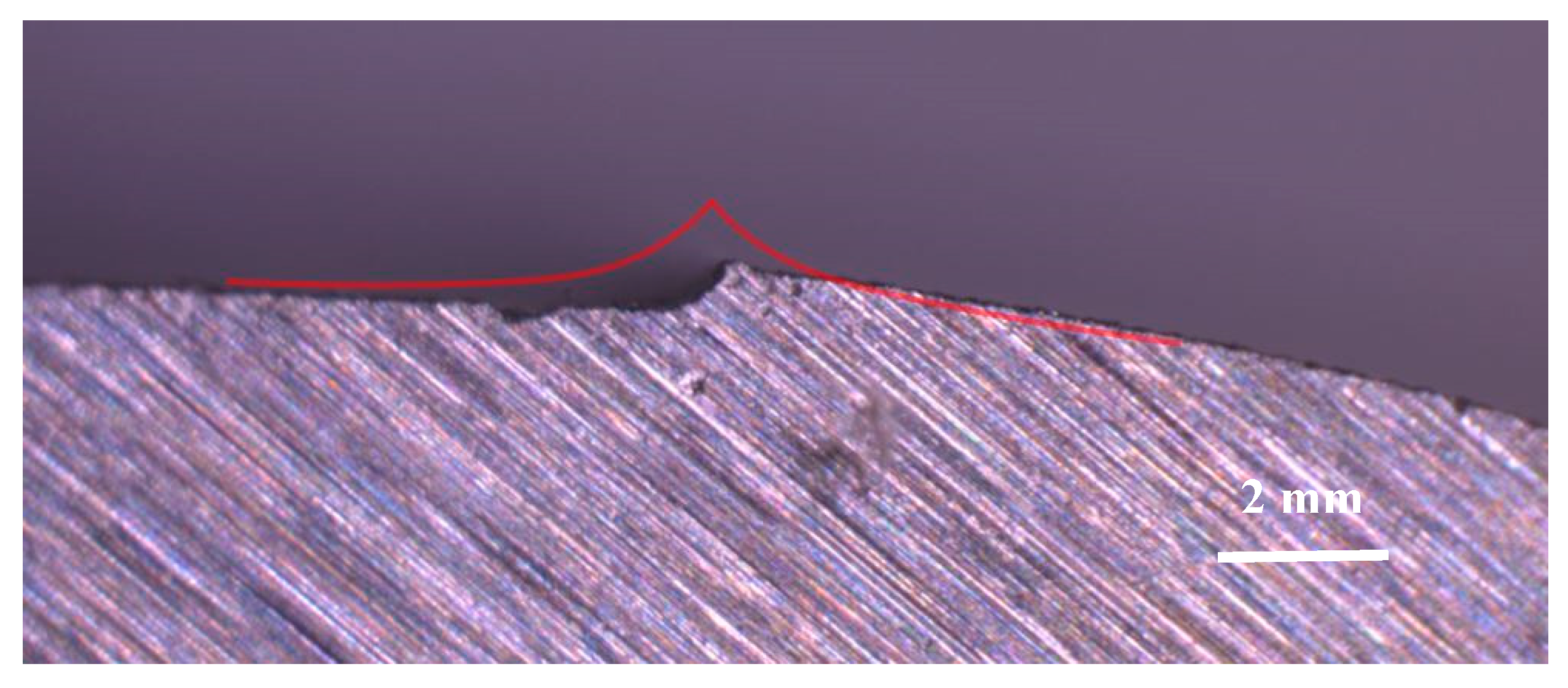
3.1. Visual Inspection

Once the two cams have been obtained, visual inspection has been performed in order to evaluate the appearance of the different machining processes.
In the milled cam, two main flaws have been detected. The first one corresponds to the mark left by the adaptable clamp that was used to fix the part in the machining center. The mark does not comprise the whole thickness of the piece, but only a local area (Figure 10). In the future, it is recommended to place a small aluminum plate between the clamp and the workpiece, in order to minimize the effect of the clamp. On the other hand, the contoured surface presented slight scratches that can be attributed to an incorrect setting of the tool or tool wear [40], although it was apparently in good condition.
In the WEDM cam, a geometric imperfection has been observed due to the entry and exit of the wire (Figure 11). This kind of shape error is inherent to this type of process if the piece does not contain any outer corner at 90°. For this reason, it has been decided to begin and end the passes tangentially to the surface of the piece, at one of the points of change of shape, in order to reduce as much as possible its influence on the quality of the cam. Figure 11 shows a detail of the workpiece, where the expected shape is shown in red. The real surface is slightly different because the force applied by the fixing magnet was not sufficient to keep the piece completely straight, and its weight has made it tilt slightly. During the cutting process, a clamping nerve is maintained in the area (Figure 12).
The WEDM surfaces offer a different appearance than the milled surface, with craters instead of cutting tool marks [6], which are produced by the electrical discharges. This gives the parts a matte color that is quite different from the bright appearance of the milled parts.

3.2. Roughness

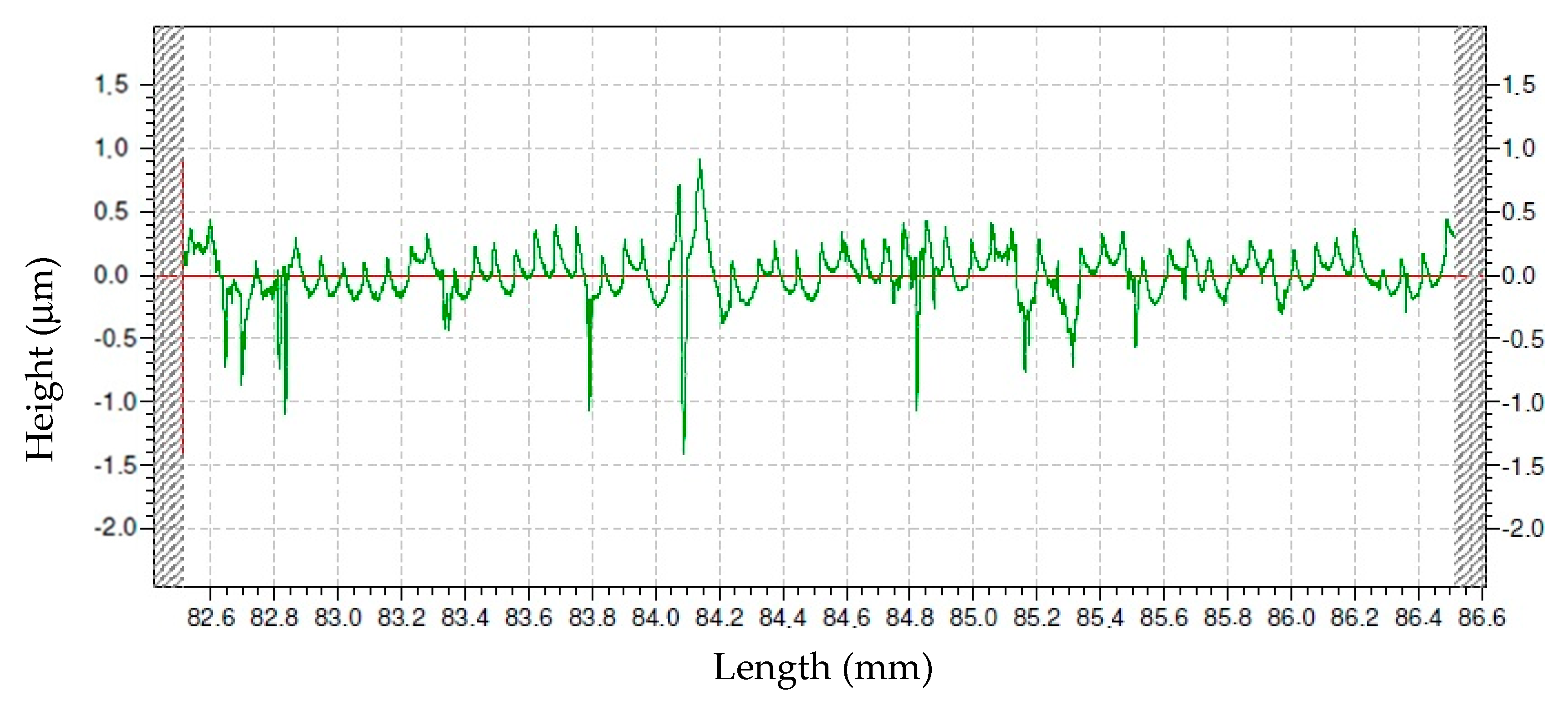
3.2.1. Roughness of the Milled Cam

Table 5 shows the roughness results of the milled cam. The highest Ra value has been found in segment 2, where the tool starts and ends the machining operation. For this reason, it does not really correspond to surface finish, but to a surface mark.
The average value of parameter Ra of the four segments is 0.269 μm, which is lower than the required roughness value below 0.4 μm for cams [30]. This is due to the fact that a finish operation has been performed, with a small feed per tooth value [41].
As an example, Figure 13 depicts the measured profile in Segment 1.
The profile is quite regular, with consecutive tool marks of approximately 0.05 mm width, corresponding to the feed value employed, and peak to valley distance of around 0.5 μm as a general trend. Some irregularities are observed, mainly deeper valleys, which can be attributed to scratches due to tool wear. The maximum peak to valley distance is around 2.4 μm.

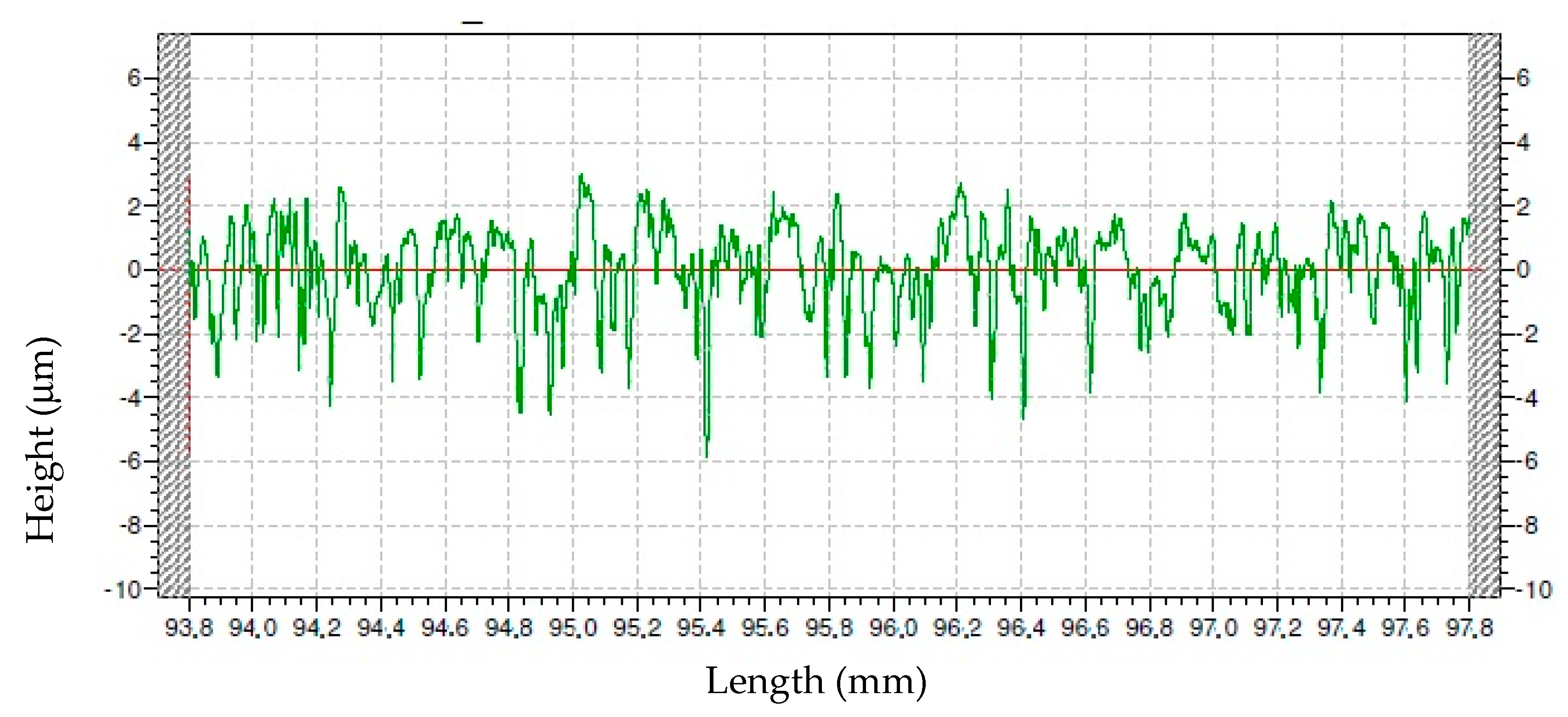
3.2.2. Roughness of the WEDM Cam

Table 6 shows the roughness results of the WEDM cam.
Segment 3 corresponds to the highest Ra value. The average Ra value of the four segments is 1.212 μm. This value is higher than that of the milled cam as expected, taking into account that only rough WEDM had been performed, and it is higher than the requirement of 0.4 μm [29].
As an example, Figure 14 shows the measured profile in Segment 1.
Figure 14 corresponds to a more irregular profile, with higher valleys than peaks, which correspond to the craters that are produced by the electrical discharges of the WEDM process. As a general trend, along the profile peak to valley distance has a value of around 6 μm. The maximum peak to valley distance is close to 9 μm.

3.3. Shape Error

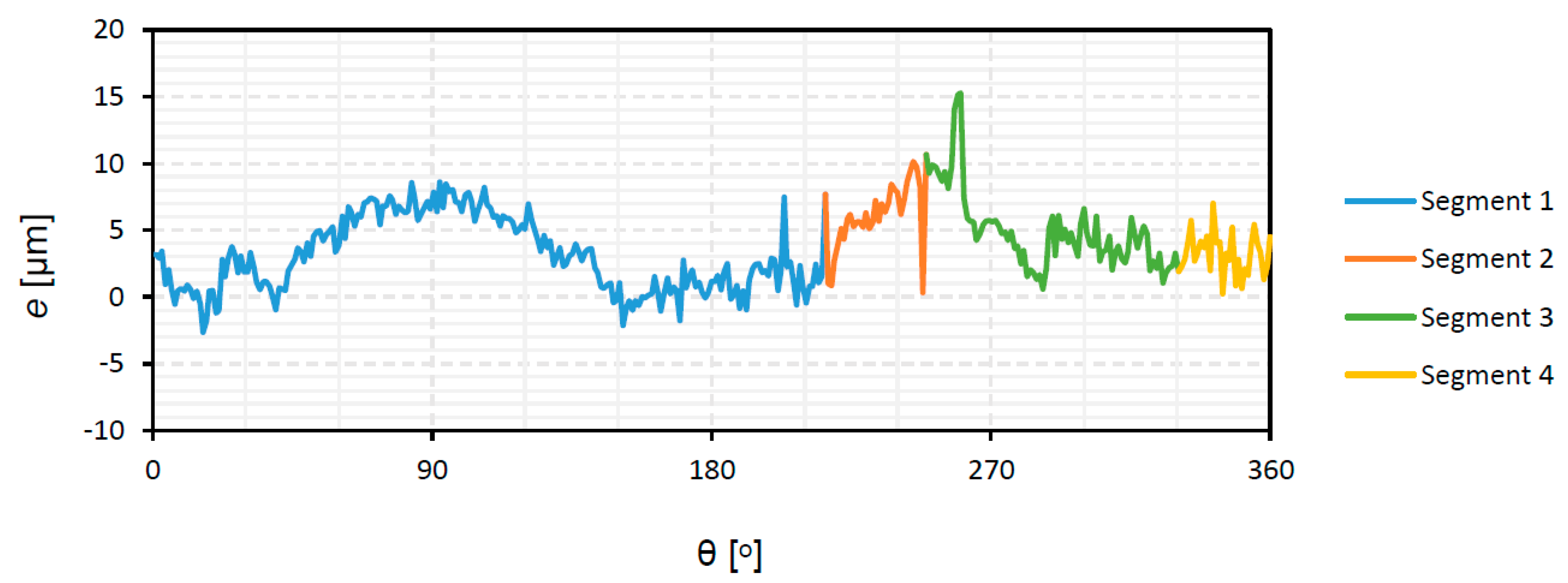
3.3.1. Shape Error of the Milled Cam

Figure 15 presents the shape error of the milled cam. It corresponds to the numerical values of the differences between the measured and the theoretical points of the cam profile, for each angle.
Along the profile, errors are mainly positive, with some small areas where they are negative. This means that the milled piece is slightly larger than the theoretical model. The highest positive difference within segment 1 is obtained at 90°, which corresponds to the end of the cam in the area of the base circle. At the end of segment 2, there is a sharp decrease in the value of the shape error up to 0 μm, followed by an increase up to 15 μm at the beginning of segment 3. Those extreme values correspond to the entry and exit of the milling tool during the machining process of the contour. The total error range is 18 μm. It is lower than the shape error that was reported by Norton, around ±25 μm for parts that were manufactured with standard milling tools [4], and similar to the value reported by Rothbart for high-speed machines, in the ±8 μm range [40]. For camshafts of combustion engines with ground lobes, lower tolerances are obtained of ±2.5 μm [14].

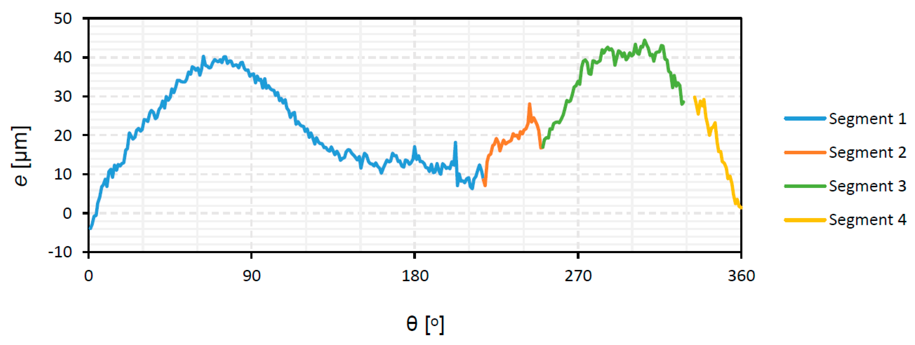
3.3.2. Shape Error of the WEDM Cam

Figure 16 presents the shape error of the WEDM cam.
In this case, the points belonging to the transition region between segments 3 and 4 have been removed, because the area that corresponds to entry and exit of the wire had been manually polished, and it is not relevant to the WEDM process. However, polishing these points is important to guarantee a smooth transition between two adjacent segments of the cam profile and thus avoid discontinuities in the follower acceleration law and keep its jerk at normal values [2]. As the authors Angeles and López-Cajún expose in their book [1], a cam-follower mechanism can produce the desired motion program with an accuracy that is only limited by that of the machine used to cut the cam [1].
The obtained piece is oversized because only a rough WEDM operation has been performed. By default, the WEDM machine leaves a material surplus, which would later require to be removed in a finishing stage. This, finishing stage would improve the accuracy and surface finish of the part and would allow for better compliance with the displacement law of the follower and its derivatives (shown in Figure 5). Slightly negative values have been observed in the transition area between Section 4 and Section 1. The shape error increases at 90°and 270°, corresponding to both ends of the cam with a curved shape, at the base circle, and the nose circle, respectively. This suggests that, as it is usual in WEDM machines, especially at high cutting speed [42], the machine has a higher deviation between the actual and programmed trajectory in corners than in straight areas. This is due to the fact that, in corners, where there is a change in the direction of movement of the guides, flexion and vibration produce deformation of the wire, with wire-lag, and the so-called back-wheel effect.
The total shape error is 48 μm. It lies within the usual range between 25 μm and 127 μm for WEDM parts in rough phases [43], although it is higher than the shape error of the milled cam.

4. Discussion

In the present paper, the option to manufacture a tangential flank cam by means of two different processes, milling, and wire electric discharge machining (WEDM), is considered. Milling is one of the most usual processes employed in the serial production of cams. However, WEDM presents several advantages that could allow the manufacture of cams in serial production: different conductive materials can be machined regardless of their hardness, more complex shapes can be obtained, and it avoids the use of pre-shaped electrodes that are necessary for SEDM [14]. Alternatively, WEDM could be used in the first rough operation to reduce the amount of material to be removed in subsequent operations [15].
The surface finish of cams is important, because low roughness reduces friction in the cam-roller contact [27]. Roughness has been measured with a contact profile meter, as is usual in metallic parts with curved surfaces [44]. Shape error is important since better accuracy of the cam profile will favor the compliance with the motion-law of the follower and, consequently, better operation of the mechanism [2]. Shape error has been measured with a coordinate measuring machine, as is usual in the measurement process of cams and other curved surfaces [24].
As for the milled cam, after a finish operation, an average Ra value of 0.269 μm has been found. This value is similar to that obtained for miniature brass gears [26]. Moreover, the milled cam meets the requirement of Ra value below 0.4 μm [30]. The shape error of the milled cam is 18 μm, which is lower than the values of ±25 μm that were reported by Norton [2], and slightly higher than those that are mentioned by Rothbart [40] for high-speed cams, of ±8 μm.
Regarding the WEDM cam, subjected only to a rough operation, an average Ra value of 1.212 μm has been measured. This suggests that the WEDM cam would require a further finish operation to meet the requirement of 0.4 μm [30]. The shape error of the WEDM cam is 48 μm. This error value is higher than that of the milled cam, and of the 21 μm reported by Hsieh and Lin for spatial cams [21]. However, it is lower than the value of 187 μm that was measured by Kang and Han [20] for marine engine cams, and it complies with the requirement of 50 μm defined by Norton [2]. Concerning the compliance of the required motion program of the cam-follower mechanism (meeting the displacement, velocity, acceleration, and jerk), in this case, the milled cam would have better compliance, and the WEDM cam would require a finish operation in order to guarantee proper compliance.
Thus, from the standpoint of quality, WEDM cams obtained with a rough operation allow obtaining the required shape error, although, a finish operation would be required in order to reduce surface roughness. From an economic point of view, a comparative study between milling, WEDM, and SEDM concluded that WEDM provides material removal rates that, although lower than those for milling, are higher than those for SEDM [15]. In the same study, it was calculated that the roughing costs of EDM are lower than the roughing costs of milling for short batches. This shows the potential of the WEDM technique for the manufacture of complex shapes, such as cams, especially in short production batches.

5. Conclusions

In the present paper, the option to obtain tangential flank cams by means of the WEDM process was considered. For this, two different cams have been manufactured by means of either milling or WEDM processes. Main conclusions are as follows:
-
The milled cam, obtained with subsequent rough and finish contour milling operations, meets both the requirements about surface roughness (average Ra = 0.269 μm < 0.4 μm) and shape error (shape error = 18 μm < 50 μm) for cams.
-
The WEDM cam, obtained with a rough operation, complies with the shape requirements (shape error = 48 μm < 50 μm), but not with the roughness requirements, with an average Ra value of 1.212. For this reason, a finish operation would be recommended, with a special clamping system to ensure the proper alignment of the part.
-
WEDM is a potential process for the manufacture of cams, especially in short production batches. Some advantages of this technique are the possibility to obtain complex shapes in different conductive materials, and the fact that, if WEDM is used in rough operations, the quantity of material to be removed in subsequent operations can be reduced.
The present study will help to develop the manufacture of tangential flank cams and other types of parts having curved surfaces by means of WEDM.

Author Contributions

Conceptualization, E.Z.-F. and À.M.-F.; methodology, E.Z.-F. and I.B.-C.; software, À.M.-F.; validation, I.B.-C. and E.Z.-F.; formal analysis, I.B.-C.; investigation, I.B.-C. and E.Z.-F.; data curation, À.M.-F.; writing—original draft preparation, I.B.-C. and E.Z.-F.; writing—review and editing, I.B.-C. and E.Z.-F.; visualization, À.M.-F.; supervision, I.B.-C. and E.Z.-F. All authors have read and agreed to the published version of the manuscript.

Funding

This research received no external funding.

Acknowledgments

The authors thank the company Cimatech S.A.C. for their help with the Cimatron software, and CIM-UPC for lending the WEDM machine. They also thank José Antonio Travieso, Alejandro Domínguez-Fernández and Ramón Casado-Lopez for their help with the experimental work.

Conflicts of Interest

The authors declare no conflict of interest.

References

  1. Angeles, J.; López-Cajún, C.S. Optimization of Cam Mechanisms; Springer: Berlin/Heidelberg, Germany, 1991. [Google Scholar]
  2. Norton, R.L. Cam Design and Manufacturing Handbook; Industrial Press Inc.: New York, NY, USA, 2002. [Google Scholar]
  3. Grant, B.; Soni, A.H. A survey of cam manufacture methods. J. Mech. Des. Trans. ASME 1979, 101, 455–464. [Google Scholar] [CrossRef]
  4. Luis Pérez, C.J.; Luri Irigoyen, R.; Fuertes Bonel, J.P.; León Iriarte, J.; Salcedo Pérez, D.; Puertas Arbizu, I. Experimental and fem analysis of wear behaviour in AA5083 ultrafine-grained cams. Metals 2020, 10, 479. [Google Scholar] [CrossRef] [Green Version]
  5. Purohit, R.; Sagar, R. Fabrication of a cam using metal matrix composites. Int. J. Adv. Manuf. Technol. 2001, 17, 644–648. [Google Scholar] [CrossRef]
  6. Mouralova, K.; Zahradnicek, R.; Benes, L.; Prokes, T.; Hrdy, R.; Fries, J. Study of micro structural material changes after WEDM based on TEM lamella analysis. Metals 2020, 10, 949. [Google Scholar] [CrossRef]
  7. Kumar, S.; Grover, S.; Walia, R.S. Effect of hybrid wire EDM conditions on generation of residual stresses in machining of HCHCr D2 tool steel under ultrasonic vibration. Int. J. Interact. Des. Manuf. 2018, 12, 1119–1137. [Google Scholar] [CrossRef]
  8. Klink, A.; Guo, Y.B.; Klocke, F. Surface integrity evolution of powder metallurgical tool steel by main cut and finishing trim cuts in wire-EDM. Proc. Procedia Eng. 2011, 19, 178–183. [Google Scholar] [CrossRef] [Green Version]
  9. Ahuja, N.; Sharma, N.; Hegab, H.; Khanna, R.; Khan, A.M. Bioactivity measurement of commercially pure titanium processed by micro-electric discharge drilling. Int. J. Adv. Manuf. Technol. 2020, 107, 2797–2805. [Google Scholar] [CrossRef]
  10. Sharma, N.; Singh, G.; Gupta, M.; Hegab, H.; Mia, M. Investigations of surface integrity, bio-activity and performance characteristics during wire-electrical discharge machining of Ti-6Al-7Nb biomedical alloy. Mater. Res. Express 2019, 6, 9. [Google Scholar] [CrossRef]
  11. Mohd Abbas, N.; Solomon, D.G.; Fuad Bahari, M. A review on current research trends in electrical discharge machining (EDM). Int. J. Mach. Tools Manuf. 2007, 47, 1214–1228. [Google Scholar] [CrossRef]
  12. García-Hernández, C.; Gella-Marín, R.M.; Huertas-Talón, J.L.; Efkolidis, N.; Kyratsis, P. WEDM manufacturing method for noncircular gears, using CAD/CAM software. Stroj. Vestn. J. Mech. Eng. 2016, 62, 137–144. [Google Scholar] [CrossRef] [Green Version]
  13. Sanchez, J.A.; Plaza, S.; De Lacalle, L.N.L.; Lamikiz, A. Computer simulation of wire-EDM taper-cutting. Int. J. Comput. Integr. Manuf. 2006, 19, 727–735. [Google Scholar] [CrossRef]
  14. Ho, K.H.; Newman, S.T.; Rahimifard, S.; Allen, R.D. State of the art in wire electrical discharge machining (WEDM). Int. J. Mach. Tools Manuf. 2004, 44, 1247–1259. [Google Scholar] [CrossRef]
  15. Klocke, F.; Zeis, M.; Klink, A.; Veselovac, D. Technological and economical comparison of roughing strategies via milling, sinking-EDM, wire-EDM and ECM for titanium- and nickel-based blisks. CIRP J. Manuf. Sci. Technol. 2013, 6, 198–203. [Google Scholar] [CrossRef]
  16. Hegab, H.A.; Gadallah, M.H.; Esawi, A.K. Modeling and optimization of Electrical Discharge Machining (EDM) using statistical design. Manuf. Rev. 2015, 2, 21. [Google Scholar] [CrossRef]
  17. Sonawane, S.A.; Kulkarni, M.L. Optimization of machining parameters of WEDM for Nimonic-75 alloy using principal component analysis integrated with Taguchi method. J. King Saud Univ. Eng. Sci. 2018, 30, 250–258. [Google Scholar] [CrossRef]
  18. Magabe, R.; Sharma, N.; Gupta, K.; Paulo Davim, J. Modeling and optimization of Wire-EDM parameters for machining of Ni55.8Ti shape memory alloy using hybrid approach of Taguchi and NSGA-II. Int. J. Adv. Manuf. Technol. 2019, 102, 1703–1717. [Google Scholar] [CrossRef]
  19. Chaudhari, R.; Vora, J.J.; Prabu, S.S.M.; Palani, I.A.; Patel, V.K.; Parikh, D.M.; de Lacalle, L.N.L. Multi-response optimization of WEDM process parameters for machining of superelastic nitinol shape-memory alloy using a heat-transfer search algorithm. Materials 2019, 12, 1277. [Google Scholar] [CrossRef] [Green Version]
  20. Kang, J.G.; Han, S. Measurement and evaluation of form deviation error of disk cam with an exclusively built profile-measuring machine. Proc. Robot. Comput. Integr. Manuf. 2010, 26, 686–693. [Google Scholar] [CrossRef]
  21. Hsieh, J.F.; Lin, P.D. Application of homogenous transformation matrix to measurement of cam profiles on coordinate measuring machines. Int. J. Mach. Tools Manuf. 2007, 47, 1593–1606. [Google Scholar] [CrossRef]
  22. Chang, W.T.; Wu, L.I. Computerized tolerance analysis of disk cam mechanisms with a roller follower. Eng. Comput. 2009, 25, 247–260. [Google Scholar] [CrossRef]
  23. Le, C.; Tan, K.N. Reconstruction of planar cam profile function and its follower displacement using B-spline curve based on inverse subdivision method and theory of contact relations—Application to cam mechanism of oscillating follower with roller. Appl. Sci. Eng. Prog. 2011, 4, 51–58. [Google Scholar]
  24. Werner, A. Method for enhanced accuracy in machining curvilinear profiles on wire-cut electrical discharge machines. Precis. Eng. 2016, 44, 75–80. [Google Scholar] [CrossRef]
  25. Gupta, K.; Jain, N.K. Comparative study of wire-EDM and hobbing for manufacturing high-quality miniature gears. Mater. Manuf. Process. 2014, 29, 1470–1476. [Google Scholar] [CrossRef]
  26. Gupta, K.; Jain, N.K. On surface integrity of miniature spur gears manufactured by wire electrical discharge machining. Int. J. Adv. Manuf. Technol. 2014, 72, 1735–1745. [Google Scholar] [CrossRef]
  27. ul Islam, T.; Khurram, M.; Umar, M.; Mufti, R.A.; Akhtar, K. Experimental and theoretical evaluation of friction in roller follower valve train. Meas. J. Int. Meas. Confed. 2020, 160, 107808. [Google Scholar] [CrossRef]
  28. Torabi, A.; Akbarzadeh, S.; Salimpour, M.; Khonsari, M.M. On the running-in behavior of cam-follower mechanism. Tribol. Int. 2018, 118, 301–313. [Google Scholar] [CrossRef]
  29. Björklund, S. The influence of surface roughness in elliptical contacts. Tribol. Int. 2001, 34, 841–845. [Google Scholar] [CrossRef]
  30. Agulló, J.; Cardona, S. Assessment of Surface Roughness (Valoración de la Rugosidad Superficial); Asociación Nacional de la Máquina—Herramienta: Spain, 1974. [Google Scholar]
  31. Veera Ajay, C.; Pradeep, B.A.; Boopathi, C.; Sanjeev, R.K.; Meganathan, V. Comparison of geometrical accuracy and surface finish of cam profile generated by wire-EDM and CNC milling machine. In Proceedings of the IOP Conference Series: Materials Science and Engineering, Volume 764, International Conference on Advances in Materials Processing and Characterization, Sathyamangalam, India, 10–11 September 2019. [Google Scholar]
  32. Bouquet, J.; Hensgen, L.; Klink, A.; Jacobs, T.; Klocke, F.; Lauwers, B. Fast production of gear prototypes—A comparison of technologies. Proc. Procedia CIRP 2014, 14, 77–82. [Google Scholar] [CrossRef]
  33. Zayas, E.E.; Cardona, S.; Jordi, L. Analysis and synthesis of the displacement function of the follower in constant-breadth cam mechanisms. Mech. Mach. Theory 2009, 44, 1938–1949. [Google Scholar] [CrossRef]
  34. Norton, R.L. Design of machinery: An Introduction to the Synthesis and Analysis of Mechanisms and Machines, 3rd ed.; Mc Graw Hill: New York, NY, USA, 2004; p. 856. [Google Scholar]
  35. Zayas, E.E.; Parra, F.; Jordi, L.; Cardona, S. QtCAM: Free software for the design and the analysis of flat cam-follower mechanisms (QtCAM: Software libre para el diseño y el análisis de mecanismos planos de leva-palpador). In Proceedings of the XXII National Conference of Mechanical Engineering of Spain, Madrid, Spain, 18–21 September 2018; pp. 875–884. [Google Scholar]
  36. DIN 6885-1: 1968. Key, Hub Keyway, Shaft Keyway Details and Dimensions; Deutsches Institut für Normung (DIN): Berlin, Germany, 1968. [Google Scholar]
  37. ISO/R 773:1969. Rectangular or Square Parallel Keys and Their Corre((Sponding Keyways (Dimensions in Millimetres); International Organization for Standardization: Geneva, Switzerland, 1969. [Google Scholar]
  38. ISO 4957:2018. Tool Steels; International Organization for Standardization: Geneva, Switzerland, 2018. [Google Scholar]
  39. ISO 4288:1996. Geometrical Product Specifications (GPS)-Surface Texture: Profile Method-Rules and Procedures for the Assessment of Surface Texture; International Organization for Standardization: Geneva, Switzerland, 1996. [Google Scholar]
  40. Rothbart, H.A.; Klipp, D.L. Cam Design Handbook. J. Mech. Des. 2004, 126, 375. [Google Scholar] [CrossRef]
  41. Buj-Corral, I.; Vivancos-Calvet, J.; Domínguez-Fernández, A. Surface topography in ball-end milling processes as a function of feed per tooth and radial depth of cut. Int. J. Mach. Tools Manuf. 2012, 53, 151–159. [Google Scholar] [CrossRef]
  42. Sanchez, J.A.; Rodil, J.L.; Herrero, A.; de Lacalle, L.N.L.; Lamikiz, A. On the influence of cutting speed limitation on the accuracy of wire-EDM corner-cutting. J. Mater. Process. Technol. 2007, 182, 574–579. [Google Scholar] [CrossRef]
  43. Sommer, C. Non-Traditional Machining Handbook, 2nd ed.; Advance Publishing Inc.: Houston, TX, USA, 2009. [Google Scholar]
  44. Buj-Corral, I.; Ortiz-Marzo, J.A.; Costa-Herrero, L.; Vivancos-Calvet, J.; Luis-Pérez, C. Optimal machining strategy selection in ball-end milling of hardened steels for injection molds. Materials 2019, 16, 860. [Google Scholar] [CrossRef] [PubMed] [Green Version]
Figure 1. (a) Parts of a disk cam mechanism with an oscillating roller follower; (b) typical tangential flank cam from a combustion engine.
Metals 10 01159 g001
Figure 2. The general methodology of the paper.
Metals 10 01159 g002
Figure 3. Camshaft of a real cam-follower mechanism used as a reference to the study.
Metals 10 01159 g003
Figure 4. (a) Measured parameter values in the reference cam-follower mechanism (length units are mm); (b) segments of the profile and maximum follower angular displacement.
Metals 10 01159 g004
Figure 5. Kinematic graphics that have been obtained with Dynacam.
Metals 10 01159 g005
Figure 6. (a) Cam-follower mechanism that has been obtained with Dynacam; (b) limit configurations with the indications of the base and nose circles in the cam profile.
Metals 10 01159 g006
Figure 7. (a) Cam designed dimensions (length units are mm); and (b) 3D printed prototype.
Metals 10 01159 g007
Figure 8. Example of the determination of the tangency points in the milled cam profile (units are mm).
Metals 10 01159 g008
Figure 9. Segments into which the measured cam profiles have been divided in the measurement process.
Metals 10 01159 g009
Figure 10. Picture of the cam surface with a flat mark and slight scratches.
Metals 10 01159 g010
Figure 11. Detail of the contour of the cam profile in the area where the wire starts and finishes cutting.
Metals 10 01159 g011
Figure 12. Detail of the required clamping nerve of the WEDM cam.
Metals 10 01159 g012
Figure 13. Graphical representation of the measured profile of the milled cam in Segment 1.
Metals 10 01159 g013
Figure 14. Graphical representation of the measured profile of the WEDM cam in Segment 1.
Metals 10 01159 g014
Figure 15. Shape error of the milled cam.
Metals 10 01159 g015
Figure 16. Shape error of the WEDM cam.
Metals 10 01159 g016
Table 1. Numerical values of the start design parameters (according to Figure 4a,b).
ParameterValue
Maximum angle of displacement of the rotating follower θmáx (°)12.13
Base radius of the cam Rb (mm)14.04
Number of sections of the profile (according to the movement law)3
Length of the follower arm lb (mm)24.25
Radius of the roller Rr (mm)10.00
Distance between rotation centers d (mm)32.82
Table 2. Quality indices of the cam-follower mechanism.
ParameterValue
Maximum pressure angle βmax (°)27.7 (limit value = 35)
Minimum radius of curvature of the cam profile Rcmin (mm)17.89 (greater than the radius of the follower)
Table 3. Main parameters of the manufacturing process of the cam.
ProcessNC MillingWEDM
MachineHaas VM-2 Machining CenterONA UE205
ToolsEnd milling cutter of diameter 20 mm and 3 teeth (rough contour milling) + end milling cutter of diameter 10 mm and 4 teeth (finish contour milling)Brass wire of diameter 0.25 mm
Fixture systemConventional vice + adaptable fixtureClamp + magnets
Cutting conditionsCutting speed 120 m/min, feed 0.15 mm (rough), feed 0.05 mm (finish), axial depth of cut 1 mm (rough), axial depth of cut 14 mm (finish), radial depth of cut 0.15 mm (finish)Voltage 130 V, feed speed 1.75 mm/min, cutting speed 2.25 mm/min
Table 4. Values of x’ translation, y’ translation, and rotation that must be applied in order to minimize the square of the distance between theoretical and manufactured profiles.
Manufacturing Processx’ Translation (mm)y’ Translation (mm)Rotation θ (°)
Milled cam−0.508−0.153114.342
WEDM cam0.0180.040118.227
Table 5. Roughness Ra in the different segments of the milled cam.
Segment1234Average
Ra (μm)0.1440.4090.2290.2950.269
Table 6. Roughness Ra in the different segments of the WEDM cam.
Segment1234Average
Ra (μm)1.0751.1321.5331.1081.212

