Abstract
Total knee arthroplasty is on the rise worldwide. Despite its success, revision surgeries are also increasing. According to the American Joint Replacement Registry 2020, 3.3% of revision surgeries are due to wear, and 24.2% are due to mechanical loosening. The combination of shear stresses and wear particles occurring at the bone/implant interface can lead to local osteolysis. Although the shear stresses are partially driven by joint friction, relatively little is known about the evolution of the coefficient of friction (CoF) during a gait cycle in total knee replacement. Here we describe the CoF during a gait cycle and investigate its association with kinematics (slide–roll-ratio), applied load, and relative velocity. The artificial knee was simulated by cobalt–chromium condyle on a flat ultra-high-molecular-weight polyethylene (UHMWPE) tibial plateau, lubricated by either water or proteinaceous solution. We found that the CoF is not a constant but fluctuates between the values close to 0 and 0.15. Cross-correlation suggested that this is primarily an effect of the slide–roll ratio and the contact pressure. There was no difference in the CoF between water and proteinaceous solution. Knowledge about the CoF behavior during a gait cycle will help to increase the accuracy of future computational models of total knee replacement.
1. Introduction
Surgery of the knee joint has become one of the most frequent surgeries. The American Joint Replacement Registry (AJRR) Annual Report, with data on 1,186,955 procedures collected from 2012 through 2017, reflects a 38% increase during that time frame—55.9% of all surgeries were total knee replacement (TKR) surgeries, and 3.8% were revision knee surgeries [1,2]. The number of TKR surgeries performed annually is rising and is expected to reach 3.48 million in the United States by 2030 [3]. The National Joint Registry (NJR) for England also reports that the number of surgeries increased by 3.8% [4]. The Australian Orthopedic Association National Joint Replacement Registry (AOANJRR) shows an increasing number of TKR as well. In 2018 alone, knee replacements increased by 1.2% compared with the previous year and revision surgeries comprised 8.7% of all TKR surgeries.
The most common material combination for these implants is an ultra-high-molecular-weight polyethylene (UHMWPE) tibial plateau articulating against a cobalt–chromium–molybdenum (CoCrMo) alloy of the femoral condyle. This combination of materials is used due to a satisfactory tribological behavior and biocompatibility [5]. However, wear of the tibial component and the release of UHMWPE particles remain of concern once the implants enter the second and third decade after implantation. There are two commonly used types of tibial bearing surfaces in UHMWPE implants: crosslinked UHMWPE (XLPE) that have been irradiated by a high dose (≥50 kGy) of gamma or electron beam radiation and the traditional, non-cross-linked UHMWPE (non-XLPE) with a lower dose of radiation applied during sterilization. The XLPE materials show lower wear rates, but different forms of crosslinking can compromise fatigue strength, limiting the implants’ longevity. This fact, together with higher costs of the XLPE, are the main reasons why the non-XLPE implants are still used. According to AJRR, 23.2% of the implants were non-XLPE implants in 2019 [6]. Using a combination of UHMWPE processing, radiation dose and optimization of geometry, we can reduce the wear rate to prevent osteolysis; thus, possibly eliminate loosening of the implant components or fractures [7]. This has motivated efforts to decrease the number of particles released into the body, such as new UHMWPEs, component packaging, and sterilization techniques [8].
One factor influencing the coefficient of friction (CoF) and related material degradation is the relative velocity at the articulating surfaces. Schwenke et al. [9] described the influence of slip velocity on the wear of total knee arthroplasty (TKA) prostheses. The term “slip velocity” describes the speed difference between two bodies acting on each other: Δ υ = υ1 − υ2. Expanding this concept, the term slide–to–roll ratio (SRR) describes their mutual movement. The slide–to–roll ratios are defined by the slip velocity based on the total speed of both bodies, described by the following equation:
as the ratio between the speed of body 1 and body 2. If one of the bodies was at a standstill, and the second of the bodies were moving, then the SSR = 2 (“simple sliding”). In the case of both bodies moving with the same velocity in the same direction (υ1 = υ2), the slip velocity would be Δυ = 0, and the SRR would be = 0 (“pure rolling”) [9].
Here, we apply this concept to daily activities. Reinders et al. have analyzed the most frequent daily activities and described them by their kinematics, load and frequency of occurrence [10]. Among those, gait is the most frequent type of human movement and has been analyzed in various studies during the last decade [11,12,13]. Gait is commonly divided into two phases, namely the stance phase and the swing phase. The stance phase describes the entire period during which the foot is on the ground. It begins with the initial contact (often by heel strike) and lasts to toe-off. The swing phase then starts with toe-off and ends with the next initial contact [14].
The International Standards Organization (ISO) published guidelines for testing implants to compare their longevity and functionality. One of the current standards used for this purpose is ISO 14243-3 for TKR wear testing [15]. This document defines the loads, rotations, and translations of the tibial component and femoral condyle to replicate a human gait cycle. These data are used as machine inputs in mechanical knee simulators, which run the implants’ motions for millions of cycles, seeking to mimic in vivo conditions. These input data will also be used in this study to investigate the CoF throughout a gait cycle.
However, running standardized wear tests on TKR devices is an expensive and time-consuming process—requiring multiple weeks of operation to reach millions of cycles. With the advent of sophisticated in silico models, a computational analysis of components is now commonly used before conducting these complicated preclinical wear tests with mechanical knee simulators [16,17,18]. These computational models rely on accurate system input parameters, for example, the CoF between the UHMWPE tibial plateau and CoCr femoral condyle. To increase the accuracy of computational models, it is necessary to improve the precision of the input parameters. Therefore, we propose combined experimental/numerical approaches to enhance the accuracy of in silico simulations (Figure 1).
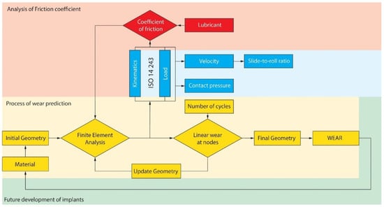
Figure 1.
Role of coefficient of friction (CoF) analysis in the process of wear prediction.
The aim of this study was to investigate the dynamic development of friction values during a whole gait cycle by taking slide–roll ratios into account and, thus, advancing the input for computational models that rely on CoF. Since it is well established that the CoF between CoCrMo and UHMWPE is dependent on the availability of protein in the lubricant [19] and applied contact pressure [20,21], we considered the influence of these factors in our experiment.
2. Materials and Methods
2.1. Articulating Bodies
Using the geometric design of a commercially available total knee implant, the velocity vectors in the tibiofemoral contact point on the medial and lateral sides were calculated for one full gait cycle [15]. The implant geometries were taken from the distal part of the MG II condyle and the central (flat) part of the corresponding tibial component (Zimmer, Inc., Warsaw, IL, USA; size: medium, left knee). A wheel-on-flat (WoF) simulator was used to analyze the CoF (Figure 2). This custom-made tribological testing device was specifically developed to test the material pairings used for artificial knee joints under controlled kinematics [22,23]. The test samples were manufactured to match the bulk and surface characteristics of current total knee replacements. The cylindrical cobalt–chromium wheel (diameter: 100 mm, width: 20 mm) was manufactured from cast material and polished to a medical-grade surface finish (Ra = 0.050 µm), with chamfered edges. The flat, rectangular PE specimen was machined from a slab molded GUR 1050 (dimension: 100 × 40 × 8 mm). Wheel and flat articulated in line contact. Samples were gamma-sterilized in nitrogen (dose: 2.5–3.25 Mrad at temp. 45 °C) and weighed before and after the experiments.
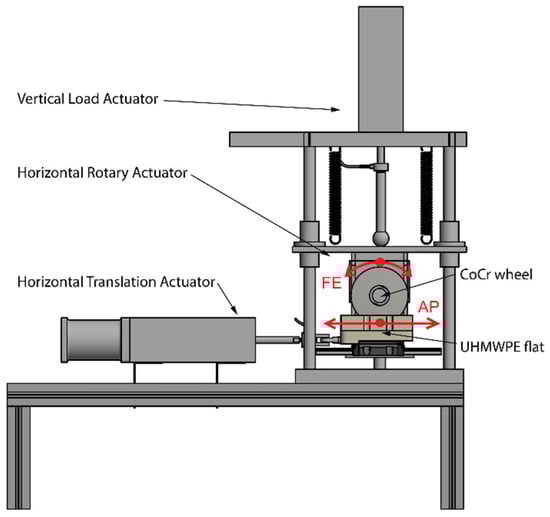
Figure 2.
A wheel-on flat simulator. The knee’s flexion–extension (FE) movement is simulated by the wheel and the anteroposterior (AP) translation by the ultra-high-molecular-weight polyethylene (UHMWPE) flat.
2.2. Lubricants
One of the factors tested was the influence of protein on friction evolution. Deionized (DI) water was used as a reference lubricant for the first set of experiments to analyze the CoF. The DI water was chosen as a reference to eliminate the influence of the protein on film formation. Following the ISO standard [15], for the second set of experiments, a protein solution based on bovine calf serum diluted with deionized water was used. The total protein concentration in the lubricant was adjusted to 30 g/L. The final solution was then filtered through a 2 µm filter and was not heated during experiments but kept at a room temperature (22 ± 2 °C). Fresh lubricant was used for each experiment to obtain a statistical sample for analysis. A chamber mounted around the UHMWPE flat sample contained 20 mL of the test lubricant. The contact area was fully submerged in the test fluid.
2.3. Friction Test Configuration
The vertically positioned wheel was pressed against the horizontally-oriented flat (Figure 2) For testing, the UHMWPE specimen was mounted on a sled that translated freely on a linear ball bearing along the horizontal axis, driven by a servo-hydraulic actuator, which was closed-loop controlled. The anteroposterior (AP) movement of the tibial plateau was simulated by a flat sample with movements ranging from 1 mm to 6 mm. The wheel represented a femoral condyle and simulated the flexion—extension (FE) movement of the knee during a gait cycle. The movements ranged from 0 deg to 60 deg and consisted of FE and AP motions as defined by the international standard for knee wear testing ISO 14243-3 (displacement control) [15]. To simulate the contact conditions of the medial compartment, 60% of the force defined by the ISO standard was applied. The applied force ranged up to 1600 N.
2.4. Contact Kinematics
Kinematics of the knee during a gait cycle were obtained from ISO14243-3 [15]. Kinematics of the knee implant in the sagittal plane was established as defined by the standard for a gait cycle. Next, the angular velocity of the wheel ωw was determined and recalculated to speed υw. Velocity of the flat υf was calculated directly. The components were moving independently in both directions to simulate mixed sliding/rolling conditions determined by two parameters: the slide–to–roll ratio (SRR) and the entrainment speed at the contact point υm = (υw + υf)/2. SRR was defined as the ratio between the relative and entrainment speed: SSR = |υr/υm|. The resulting SRR was determined by the following equation:
SRR was obtained operationally from the speed values between the wheel and the flat during the measurements. Results of SRR were obtained from 10 measurements described by an average value and standard deviation for each percent of the entire gait cycle. The speeds were calculated using the values of the wheel velocity obtained from the angular sensor and the flat velocity obtained by the position sensor. The applied load was either fixed at a certain level or represented the dynamic behavior of the load during a single gait cycle (ISO).
2.5. Controller and Data Acquisition
Movements of the hydraulic actuators were driven by the MTS controller (MTS System Corporation, Minneapolis (MN), USA). All three actuators accepted independent, custom-made profiles according to the ISO standard and were implemented with a tolerance of ±5% of the maximum value and ±3% of the full cycle time for phasing. All profiles were synchronized at the starting position. The horizontal and vertical translation actuator position was captured by LVDT sensors, and the position of the horizontal rotary actuator was captured by an angular position sensor (continuous, sensitivity ±0.2°) in a controlled loop. Output data were measured by two force sensors mounted on the actuator shafts. The loading magnitude varied and was recorded using a force sensor (range 0 to 2 kN; sensitivity ±0.5%). The second sensor (range 0 to 2 kN; sensitivity ±0.5%) measured the tangential force between the wheel and the flat.
2.6. Measurements
For this study, displacement characteristics of the wheel and the flat were programmed for a period of 1 s. The frequency of the movement corresponded to one entire cycle of human gait. One hundred points were used for programming the cycle. Deionized water was used as a reference lubricant for the first group of measurements, and a protein solution containing 30 g/L of protein based on a bovine serum prepared according to the ISO standard was used for the second group of measurements.
The experiment was repeated 10 times at each (constant) load level of 200, 500, 800, 1100, 1400 N. Each load level was repeated using the same lubricant, but for every load level, fresh lubricant was used. After a running-in period of five gait cycles, the CoF measurements were conducted. Ten gait cycles were recorded for each load level. In addition, a dynamic load pattern was analyzed. The load pattern followed the ISO standard but applied was reduced to 60 percent since the wheel modeled the medial condyle only. The dynamic load experiment was repeated ten times, and for each experiment, a fresh lubricant sample was used. For both the constant and dynamic load experiments, the resulting values were logged with a sampling rate of 300 Hz. Positions of the wheel and the flat were also recorded during the experiment. The relative velocity of the components during the gait cycle was calculated as the ratio of the position and the time. After each gait cycle, one peak in each cycle was used for the temporal alignment of data and the identification of the beginning of the gait cycle.
2.7. Friction Force Correction
Since the results of the tangential force could be influenced by acceleration and deceleration of the sled’s mass and by intrinsic friction forces of the sled’s linear ball bearing, a correction curve was determined. For this, measurements were conducted without any applied load; only the translational movement of the sled was executed. The obtained friction values were subtracted from the tangential force measurements during the operation.
2.8. Sample Inspection
After the test, samples were inspected using a digital microscope (Keyence VHX-6000, Osaka, Japan). In addition, the surface topography of the wheel was analyzed by phase-shifting interferometry (Bruker Contour GT-X, Billerica, MA, USA) to obtain roughness parameters.
2.9. Data Analysis
An important variable of interest was the availability of protein in the lubricant. The difference in CoF between DI water and protein lubricant throughout a standardized gait cycle was evaluated by a two-tailed two-sample t-test statistical parametric map, or SPM [24]. SPM (t) is the output statistics that are evaluated at every time point in the series at α = 5% (a typical probability threshold for rejecting the null hypothesis in biomedical research). All the adjacent measurement points that lie beyond the threshold are termed “supra-threshold clusters”. MATLAB package spm1d (The MathWorks Inc., Natick, MA, USA) was used to calculate p-values for each cluster [25]. Pattern similarity between CoF and SRR, load, and/or velocity was investigated using normalized cross-correlation as a function of time shift for both the DI water and the protein solution. Finally, the effect of load level on the average friction value was investigated using the one-way analysis of variance (ANOVA). Tukey’s multiple comparisons test was used for the post hoc analysis.
3. Results
Initially, force disturbances that contributed erroneously to the friction force were analyzed, so measured friction forces in subsequent experiments could be corrected. Figure 3 displays the average with the maximum and minimum values of 10 cyclic measurements. AP movement profiles were within tolerances defined by ISO 14243.
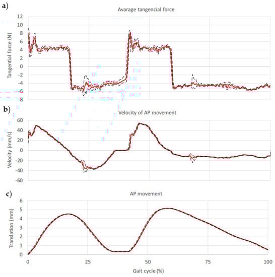
Figure 3.
(a) Results of the tangential force for unloaded flat sample involve friction of linear bearing and accel/deceleration contribution (b) velocity calculated according to the real position during the simulated gait cycle (c) movement of a flat sample.
The evolution of the CoF during a standardized gait cycle is shown for both lubricants in Figure 4. Load and SRR are plotted over the same time axis. For SRR, values near 2 are “pure sliding,” and 0 is “pure rolling” of the components. The resulting values were divided into the two basic phases of gait. The average CoF during the stance phase was 0.034 (SD 0.017) when the protein lubricant was used and 0.038 (SD 0.019) under pure water lubrication. During the swing phase, the average CoF was 0.052 (SD 0.022) in protein solution and 0.055 (SD 0.024) in deionized water.
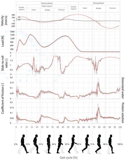
Figure 4.
Development of the friction coefficient for the entire gait cycle with deionized water and protein solution as a lubricant.
A comparison of the CoF curves by SPM (Figure 5) shows a slight difference between the lubricants for most of the cycle. Looking at the supra-threshold clusters, the largest differences were found in the middle/terminal stance phase (32–52% and the terminal swing phase (96–100%). The probability clusters of these sizes would arise from the random samplings with p < 0.001. They arise during a constant load increase, and we speculate that the protein interferes with the friction adjustment.
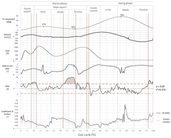
Figure 5.
Comparison of coefficients of friction for deionized water and protein solution.
Using the cross-correlation to investigate the similarity between the CoF and load, velocity, and SRR, the highest correlation coefficient was found between CoF and SRR, reaching a peak of 0.75. The correlation between CoF and load reached the next highest correlation coefficient, while velocity had no influence (Figure 6).
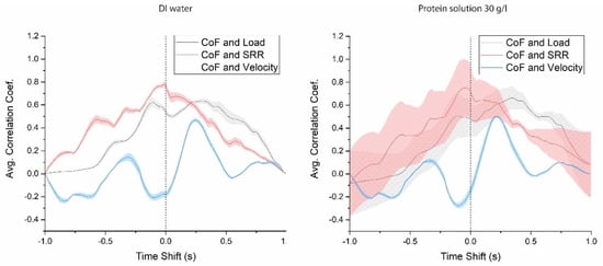
Figure 6.
The normalized cross-correlation between load, slide–roll ratio (SRR), and velocity on CoF in deionized water (left) and protein solution (right).
An additional experiment at various load levels at constant 200, 500, 800, 1100 and 1400 N was conducted using the protein lubricant. Figure 7 displays the CoF values (the average value from 10 cycles) within the range of loads of the gait cycle. The load of 200 N had an average CoF of 0.056 (SD 0.001) for 10 gait cycles. As the load level increased, the CoF decreased. The lowest CoF value of 0.023 (SD 0.001) was measured for the constant load of 1400 N. Figure 8 shows 10 average values for each of the 10 cycles. All CoF values were highly significantly different from each other (p < 0.001). In both figures, the results were also compared to those dynamically loaded according to the ISO 14243-3 protocol. The basic characteristics of the friction evolution were preserved throughout all load levels.
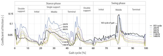
Figure 7.
Evolution of friction coefficient and velocity for the entire gait cycle with a constant load.
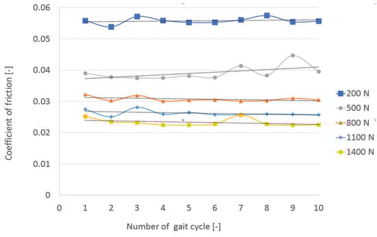
Figure 8.
Ten average values of the friction coefficient under different loads for each gait cycle.
After the test, samples were microscopically inspected. The wheel did not show any scratches or adherent UHMWPE particles/material. Using interferometry, its surface roughness was determined to Ra = 0.068 µm. Other roughness features were unremarkable. On the UHMWPE flat, the contact path was macroscopically visible. Using light microscopy, slight polishing of the machining marks could be identified (Figure 9).
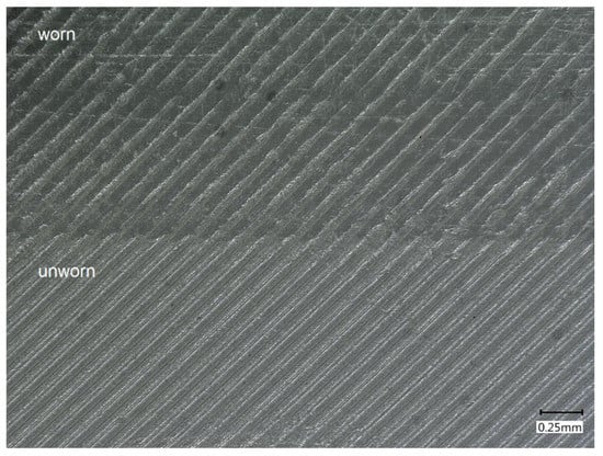
Figure 9.
Light microscopy image of the UHMWPE flat showing both worn and unworn regions.
4. Discussion
This study aimed to identify parameters influencing the evolution of the CoF during a full gait cycle in the presence or absence of protein in the lubricant. Among the parameters investigated, the slide–roll-ratio (SRR) between the contacting bodies had the most significant influence. It was followed by the contact pressure that still clearly changed the pattern of the friction curve. The relative velocity between the contacting bodies had an insignificant influence. These findings were true for both deionized water and the protein-containing solution and showed surprisingly insignificant differences, with the greatest effect between the mid and terminal stances. An analysis of different load levels confirmed the existing literature that a rise in contact pressure leads to a decrease in friction CoF [20], but it also demonstrated that contact pressure is only one factor.
The contact pressure was calculated using the Hertzian Theory for a linear contact between cylinders. The input load was adjusted to 60 percent of the load (F) defined by the ISO standard since 60% of the total load corresponds to the values of the contact pressure of the medial condyle [26]. As described, the wheel is supposed to model a single condyle.
The calculated contact pressure was compared with previous studies on contact pressure in knee replacements [27,28,29,30]. The authors of these studies stated that the maximum contact pressure for the medial condyle could reach up to 25 MPa (Figure 10). In our study, a maximum contact pressure of 21 MPa was determined, which is within that range.
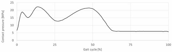
Figure 10.
Contact pressure during the gait cycle for the linear contact of the WoF simulator–medial condyle.
The applied contact pressure influences the CoF, as shown in this study and as previously determined [20,31]. It is well understood that, for polymers, the CoF is not independent of contact pressure. Based on theoretical considerations, since for many polymers, the contact is perfectly elastic, Yamaguchi suggested that the CoF is reciprocally related to the cube root of the contact pressure [32]. It is necessary to mention that the friction was measured without separating surface friction from any viscoelastic losses in bulk.
The relationship between the CoF and the load seems to be roughly preserved in our data set. In Figure 7, at first glance, the trends in CoF change during the gait for different static loads. For most of the gait cycle, the CoF patterns are only offset from each other in magnitude, with low loads yielding higher CoF values. The results include the standard deviation for each gait cycle. These findings were supported by Saikko, Schröder, and Wang et al. [20,31,33]. The three of them found a decrease in the sliding friction coefficient of UHMWPE articulating against the cobalt–chromium alloy with increasing contact pressure. Each of the studies used a different configuration of the tested samples. Table 1 summarizes the literature data.

Table 1.
Load-dependent friction coefficient of UHMWPE against the CoCr alloy compared to references; the coefficients of friction were calculated from the determined exponential formulas of publications.
The reported range of friction values of UHMWPE articulating against metallic materials is quite large. Soudry and Walker analyzed the friction of total knee replacements using cadaver specimens with implanted prostheses and water as a lubricant. The friction coefficient varied between 0.021 and 0.041 [36]. Denton et al. performed cylinder-on-plate tests with water lubrication. After running-in, the coefficient of friction increased from 0.03 to approximately 0.1 [37]. Schröder et al. [34] found similar sliding friction values (0.07 to 0.10) for different prosthetic materials. The differences between the studies are mainly influenced by contact pressure, the utilized component materials, and the applied kinematics. In our study, the coefficient of friction varied between 0.004 and 0.15. These values are only slightly different between the protein solution and DI water (Figure 5). For DI water, the mean value of the CoF was 0.038 (SD 0.019) in the stance phase and 0.055 (SD 0.024) in the swing phase. The mean friction coefficient for the protein serum was 0.034 (SD 0.017) in the stance phase and 0.052 (SD 0.022) in the swing phase. Differences between the mean values are not substantial, but a more detailed analysis using SPM revealed sections that were statistically significantly different from each other. A combination of factors may have caused this; SRR being one of them, dynamically forming the film of lubricant and thus influencing the CoF.
Changing velocities and direction of the rotation of the knee components during measurements were associated with a changing CoF. The first change of the component rotation was at 17% of the gait cycle, with knee flexion up to 15 deg. The second change was at the transition from the extension to the flexion at 41% of the gait cycle. The third change was in the middle of the swing phase (76%) when the unloaded limb swung forward up to 57 deg. These changes were followed by the peaks observed in the SRR. In the first and the second case, the velocities were up to 100 mm/s, and the load around 1200 N. The CoF decreased in both cases. In the third case (the swing phase), the velocity changed from 200 to −200 mm/s, and the load was only around 100 N. This condition led to an increase in CoF.
The influence of the SRR on the film formation was described in detail by a study of Necas et al. This study observed two main proteins and described their behavior in the contact area. A thin layer of γ-globulin was first absorbed into the rubbing surfaces, enabling the albumin to absorb and to create a layered structure [38,39]. In our case, the quick changes in the components’ rotation could lead to disruption of the lubricant layer and CoF peaks during the swing phase (up to 0.15). At the same time, the film thickness increased quite rapidly for some time under the positive sliding conditions and then it started to decrease to almost a negligible level, which could lead to stabilization of the CoF during the gait cycle, which was also supported by the results of the stance phase of the experiment.
Significant differences between the stance phase and the swing phase are related to the difference in the load, as could have been expected from the Yamaguchi model [32]. When the joint was unloaded, the CoF increased, as shown by measurements in Figure 7 [14]. The stance phase, where the limb is loaded with a maximum load of 1528 N, is followed by the swing phase, where the limb is unloaded and swung forward, reaching only a maximum of 110 N for the medial condyle. The impetus to carry out tests with constant loads was based on the strong influence of load on the development of the CoF.
Interestingly, the CoF offsets for the static load cases collapse and values become erratic only during times of rapid SRR change. This could be due to the changes in fluid films having a greater impact on the system than load effects during these turbulent phases. In Figure 7, we can also observe where the changes in the CoF pattern for the ISO-load case deviate from the static load trends. This is most clearly seen in the double support phases in stance, and both of these times align with rapid changes in applied load. This further highlights the need for more complex CoF inputs for computational models—CoF values generated from static load tests would not capture these phenomena.
Lundberg et al. developed parametric methods for computing contact forces across the knee joint for various activities. This approach allows for the physiological inclusion of all muscles crossing the knee joint [17,40]. Based on these mathematical approaches, a computational framework utilizing finite element analysis (FEA) for modeling the wear of TKRs was developed. Mell et al. used this approach for wear prediction. Values of the friction coefficient between the two articulating surfaces were set as a mean value of 0.04 [16,41]. Godest et al. performed FEA with coefficients of friction of 0.01, 0.04, and 0.07. The results clearly show the influence of friction on the predicted AP translations, internal–external rotations, and the peak contact pressures [42]. There is a paucity of studies dealing with a dynamic description of the CoF. The majority of the FEA models implement friction as a constant number. The results in Figure 5 show a dynamic behavior of the CoF with joint movement. When simplifying the value, distortion of the results may occur mainly for the protein serum used as a lubricant. As the results show in Figure 5. Comparison of coefficients of friction for DI water and protein solution., there are some differences in the behavior of the CoF for different lubricants. The differences can be driven by partial constituents of the lubricant that are differently affected by the dynamic parameters, such as the changing SRR or load. For the reliability of the models, the analysis of the CoF for different movements is important. More research is necessary to quantify the influence of CoF variation according to the input values and the reliability of FEA models.
This study has several limitations. The complexity of the measurements required certain system simplifications that may have affected the results. Firstly, the geometry of the tibial part was reduced to a flat surface. This allowed us to analyze the CoF without constraining forces from geometry, but at the same time, it may have changed contact conformity, possibly influencing the lubrication regime of the implant. Secondly, the analyzed movements included FE motion and AP translation only. The internal–external rotation of the flat was neglected to simplify CoF analysis. Orientation of FE rotation and AP translation were chosen so that no cross-shear would occur, i.e., the sliding velocity vector would follow the predominant molecular orientation of UHMWPE fibrils. This alignment may have affected the CoF. Thirdly, another limitation of the study is the number of tested samples. This study was performed with a single-bearing couple that may limit generalizability. However, our focus was on other influencing variables than material. It is unlikely that the observations performed would change with additional bearing couples included, although friction values might slightly adjust. Fourthly, in addition to the CoCrMo surface finish, the topography of the softer polymer may also influence the frictional properties of the articulation, as discussed theoretically by Dowson et.al. [43]. It is hypothesized that any morphological change at the surface will alter the general frictional conditions under which the prosthesis is functioning and, thus, may modify its kinematic properties during its time in situ and, at the same time, it may alter the conditions for lubrication film formation [44]. This must be investigated in future studies. Here, the surface topography of flat was only slightly eroded during the course of the experiment. Lastly, friction was analyzed for a single movement pattern—the ISO gait cycle. Other activities, such as stair ascent, stair descent, and potentially selected sports activities, such as cycling or jogging, should be studied in the future.
Future research will also include kinematic enhancements of the simulator with the inclusion of internal-external rotation and the elimination of disturbances, such as the parasitic friction in the linear bearing and the mass of any moving parts that require curve correction.
Despite these limitations, we believe that our study successfully demonstrated the evolution of the CoF during human gait and illuminated the slide–roll ratio and the contact load as important variables influencing the friction value.
5. Conclusions
This study demonstrated the dynamic friction evolution of a CoCrMo/UHMWPE knee joint model during a human gait cycle. It was shown that the CoF value changes depending on the slide–roll ratio (SRR) and the contact pressure.
Significant knee rotation changes were observed at 17%, 41% and 76% of the gait cycle, followed by peaks in the SRR leading to different conditions for film formation. These abrupt changes in SRR were associated with a rapid change in CoF.
Increasing the load level from 200 N to 1400 N brought about decreasing CoF values. These findings were true for both the deionized water and the protein-containing solution. The lowest CoF value of 0.023 was found for a load of 1400 N in proteinaceous solution.
A better understanding of the dynamic friction evolution in total knee replacement will lead to better in silico models in the future. To advance these models, it is important to replace simplified (constant) friction values with parameters that reflect the CoF dynamic range and behavior during daily activities.
Author Contributions
Conceptualization, M.R., M.A.W., and S.F.; methodology, M.R. and M.A.W.; formal analysis, S.F.; investigation, M.R. and M.A.W.; resources, M.A.W.; data curation, M.R.; writing—original draft preparation, M.R.; writing—review and editing, M.A.W. and M.V.; visualization, M.R.; supervision, M.A.W.; project administration, M.V.; funding acquisition, I.K. All authors have read and agreed to the published version of the manuscript.
Acknowledgments
This research was carried out under the project LTAUSA17150 with financial support from the Ministry of Education, Youth and Sports of the Czech Republic. Additional support was obtained from the Galante Family Foundation, which is greatly acknowledged. Partial support of NIH R01AR059843 for simulator development is recognized.
Conflicts of Interest
The authors declare no conflict of interest.
References
- The American Joint Replacement Registry. The AJRR 2018 Annual Report: THA/TKA Surgical Insights Summary and Beyond; American Academy of Orthopaedic Surgeons (AAOS) Registry Program: Rosemont, IL, USA, 2018. [Google Scholar]
- Heckmann, N.; Ihn, H.; Stefl, M.; Etkin, C.D.; Springer, B.D.; Berry, D.J.; Lieberman, J.R. Early Results From the American Joint Replacement Registry: A Comparison With Other National Registries. J. Arthroplast. 2019, 34, S125–S134.e1. [Google Scholar] [CrossRef]
- Kurtz, S.; Ong, K.; Lau, E.; Mowat, F.; Halpern, M. Projections of Primary and Revision Hip and Knee Arthroplasty in the United States from 2005 to 2030. J. Bone Jt. Surg. Am. Vol. 2007, 89, 780–785. [Google Scholar] [CrossRef]
- Registry, N.J. National Joint Registry for England, Wales and Northern Ireland; National Joint Registry: London, England, 2017; p. 202. ISSN 2054-1821. [Google Scholar]
- Kurtz, S.M. UHMWPE Biomaterials Handbook: Ultra High Molecular Weight Polyethylene in Total Joint Replacement and Medical Devices, 3rd ed.; Elsevier Inc.: Amsterdam, The Netherlands, 2015; pp. 1–815. [Google Scholar] [CrossRef]
- The Seventh Annual Report of the AJRR on Hip and Knee Arthroplasty; American Academy of Orthopaedic Surgeons (AAOS): Rosemont, IL, USA, 2020.
- Buckley, C.P.; Wu, J.; Haughie, D.W. The integrity of welded interfaces in ultra high molecular weight polyethylene: Part 1—Model. Biomaterials 2006, 27, 3178–3186. [Google Scholar] [CrossRef]
- Chakravarty, R.; Elmallah, R.D.K.; Cherian, J.J.; Kurtz, S.M.; Mont, M.A. Polyethylene Wear in Knee Arthroplasty. J. Knee Surg. 2015, 28, 370–375. [Google Scholar] [CrossRef] [PubMed]
- Schwenke, T.; Borgstede, L.; Schneider, E.; Andriacchi, T.; Wimmer, M. The influence of slip velocity on wear of total knee arthroplasty. Wear 2005, 259, 926–932. [Google Scholar] [CrossRef]
- Reinders, J.; Sonntag, R.; Vot, L.; Gibney, C.; Nowack, M.; Kretzer, J.P. Wear Testing of Moderate Activities of Daily Living Using In Vivo Measured Knee Joint Loading. PLoS ONE 2015, 10, e0123155. [Google Scholar] [CrossRef] [PubMed]
- Tsai, T.-Y.; Li, J.-S.; Wang, S.; Scarborough, D.; Kwon, Y.-M. In-vivo 6 degrees-of-freedom kinematics of metal-on-polyethylene total hip arthroplasty during gait. J. Biomech. 2014, 47, 1572–1576. [Google Scholar] [CrossRef] [PubMed]
- Tanimoto, K.; Takahashi, M.; Tokuda, K.; Sawada, T.; Anan, M.; Shinkoda, K. Lower limb kinematics during the swing phase in patients with knee osteoarthritis measured using an inertial sensor. Gait Posture 2017, 57, 236–240. [Google Scholar] [CrossRef] [PubMed]
- Washabaugh, E.P.; Augenstein, T.E.; Krishnan, C. Functional resistance training during walking: Mode of application differentially affects gait biomechanics and muscle activation patterns. Gait Posture 2020, 75, 129–136. [Google Scholar] [CrossRef]
- Kharb, A.; Saini, V.; Jain, Y.; Dhiman, S. A review of gait cycle and its parameters. Int. J. Multiscale Comput. Eng. 2011, 13, 78–83. [Google Scholar]
- ISO14243-3. ISO14243-3. ISO 14243-3, Implants for surgery—Wear of total knee-joint prostheses. In Part 3: Loading and Displacement Parameters for Wear-Testing Machines with Displacement Control and Corresponding Environmental Conditions for Test; ISO Copyright Office: Geneva, Switzerland, 2014; p. 16. [Google Scholar]
- Mell, S.P.; Fullam, S.A.; Wimmer, M.; Lundberg, H.J. Finite element evaluation of the newest ISO testing standard for polyethylene total knee replacement liners. Proc. Inst. Mech. Eng. Part H J. Eng. Med. 2018, 232, 545–552. [Google Scholar] [CrossRef]
- Lundberg, H.J.; Foucher, K.C.; Wimmer, M.A. A parametric approach to numerical modeling of TKR contact forces. J. Biomech. 2009, 42, 541–545. [Google Scholar] [CrossRef] [PubMed][Green Version]
- Knight, L.A.; Pal, S.; Coleman, J.C.; Bronson, F.; Haider, H.; Levine, D.L.; Taylor, M.; Rullkoetter, P.J. Comparison of long-term numerical and experimental total knee replacement wear during simulated gait loading. J. Biomech. 2007, 40, 1550–1558. [Google Scholar] [CrossRef]
- Serro, A.; Gispert, M.; Martins, M.; Brogueira, P.; Colaco, R.; Saramago, B. Adsorption of albumin on prosthetic materials: Implication for tribological behavior. J. Biomed. Mater. Res. Part A 2006, 78, 581–589. [Google Scholar] [CrossRef] [PubMed]
- Saikko, V. Effect of contact pressure on wear and friction of ultra-high molecular weight polyethylene in multidirectional sliding. Proc. Inst. Mech. Eng. Part H J. Eng. Med. 2006, 220, 723–731. [Google Scholar] [CrossRef]
- Vassiliou, K.; Unsworth, A. Is the wear factor in total joint replacements dependent on the nominal contact stress in ultra-high molecular weight polyethylene contacts? Proc. Inst. Mech. Eng. Part H J. Eng. Med. 2004, 218, 101–107. [Google Scholar] [CrossRef]
- Wimmer, M.A.O.; Birken, L.M.; Sellenschloh, K.; Schneider, E. Damage due to rolling in total knee replacement—The influence of tractive force. Friction 2013, 1, 178–185. [Google Scholar] [CrossRef]
- Schwenke, T.; Wimmer, M.A. Cross-shear in metal-on-polyethylene articulation of orthopaedic implants and its relationship to wear. Wear 2013, 301, 168–174. [Google Scholar] [CrossRef] [PubMed][Green Version]
- Friston, K. CHAPTER 2—Statistical parametric mapping. In Statistical Parametric Mapping; Friston, K., Ashburner, J., Kiebel, S., Nichols, T., Penny, W., Eds.; Academic Press: London, UK, 2007; pp. 10–31. [Google Scholar] [CrossRef]
- Pataky, T.C. Generalized n-dimensional biomechanical field analysis using statistical parametric mapping. J. Biomech. 2010, 43, 1976–1982. [Google Scholar] [CrossRef]
- Johnson, K.L. Adhesion and friction between a smooth elastic spherical asperity and a plane surface. Proc. R. Soc. A Math. Phys. Eng. Sci. 1997, 453, 163–179. [Google Scholar] [CrossRef]
- Ardestani, M.M.; Moazen, M.; Chen, Z.; Zhang, J.; Jin, Z. A real-time topography of maximum contact pressure distribution at medial tibiofemoral knee implant during gait: Application to knee rehabilitation. Neurocomputing 2015, 154, 174–188. [Google Scholar] [CrossRef]
- Guo, Y.; Zhang, X.; Chen, W. Three-Dimensional Finite Element Simulation of Total Knee Joint in Gait Cycle. Acta Mech. Solida Sin. 2009, 22, 347–351. [Google Scholar] [CrossRef]
- Wang, H.; Chen, T.; Torzilli, P.; Warren, R.; Maher, S. Dynamic contact stress patterns on the tibial plateaus during simulated gait: A novel application of normalized cross correlation. J. Biomech. 2014, 47, 568–574. [Google Scholar] [CrossRef] [PubMed][Green Version]
- Barceinas-Sanchez, J.; Alvarez-Vera, M.; Montoya-Santiyanes, L.; Dominguez-Lopez, I.; Garcia-Garcia, A.; Garcia-Garcia, A. The coefficient of friction of UHMWPE along an entire walking cycle using a ball-on-disc tribometer under arthrokinematics and loading conditions prescribed by ISO 14243-3:2014. J. Mech. Behav. Biomed. Mater. 2017, 65, 274–280. [Google Scholar] [CrossRef] [PubMed]
- Wang, A.; Essner, A.; Klein, R. Effect of contact stress on friction and wear of ultra-high molecular weight polyethylene in total hip replacement. Proc. Inst. Mech. Eng. Part H J. Eng. Med. 2001, 215, 133–139. [Google Scholar] [CrossRef] [PubMed]
- Yamaguchi, Y. Tribology of Plastic Materials: Their Characteristics and Applications to Sliding Components; Elsevier: Amsterdam, The Netherlands, 1990; Volume 16. [Google Scholar]
- Schroder, D.T.; Kelly, N.H.; Wright, T.M.; Parks, M.L. Retrieved Highly Crosslinked UHMWPE Acetabular Liners Have Similar Wear Damage as Conventional UHMWPE. Clin. Orthop. Relat. Res. 2011, 469, 387–394. [Google Scholar] [CrossRef]
- Schröder, C.; Steinbrück, A.; Müller, T.; Woiczinski, M.; Chevalier, Y.; Weber, P.; Müller, P.E.; Jansson, V. Rapid Prototyping forIn VitroKnee Rig Investigations of Prosthetized Knee Biomechanics: Comparison with Cobalt-Chromium Alloy Implant Material. BioMed Res. Int. 2015, 2015, 1–9. [Google Scholar] [CrossRef]
- Saikko, V. Effect of Contact Area on the Wear and Friction of UHMWPE in Circular Translation Pin-on-Disk Tests. J. Tribol. 2017, 139, 061606. [Google Scholar] [CrossRef]
- Soudry, M.; Walker, P.; Reilly, D.; Kurosawa, H.; Sledge, C. Effects of total knee replacement design on femoral—Tibial contact conditions. J. Arthroplast. 1986, 1, 35–45. [Google Scholar] [CrossRef]
- Denton, R. Wear and Friction of Elastomers; ASTM International: West Conshohocken, PA, USA, 1992. [Google Scholar] [CrossRef]
- Nečas, D.; Vrbka, M.; Urban, F.; Křupka, I.; Hartl, M. The effect of lubricant constituents on lubrication mechanisms in hip joint replacements. J. Mech. Behav. Biomed. Mater. 2016, 55, 295–307. [Google Scholar] [CrossRef]
- Nakashima, K.; Sawae, Y.; Murakami, T. Effect of conformational changes and differences of proteins on frictional properties of poly(vinyl alcohol) hydrogel. Tribol. Int. 2007, 40, 1423–1427. [Google Scholar] [CrossRef]
- Lundberg, H.J.; Knowlton, C.; Wimmer, M.A. Fine Tuning Total Knee Replacement Contact Force Prediction Algorithms Using Blinded Model Validation. J. Biomech. Eng. 2013, 135, 021015–0210159. [Google Scholar] [CrossRef] [PubMed]
- Mell, S.P.; Wimmer, M.A.; Lundberg, H.J. The choice of the femoral center of rotation affects material loss in total knee replacement wear testing—A parametric finite element study of ISO 14243-3. J. Biomech. 2019, 88, 104–112. [Google Scholar] [CrossRef] [PubMed]
- Godest, A.; Beaugonin, M.; Haug, E.; Taylor, M.; Gregson, P. Simulation of a knee joint replacement during a gait cycle using explicit finite element analysis. J. Biomech. 2002, 35, 267–275. [Google Scholar] [CrossRef]
- Dowson, D.; Diab, M.M.E.-H.; Gillis, B.J.; Atkinson, J.R. Influence of Counterface Topography on the Wear of Ultra High Molecular Weight Polyethylene Under Wet or Dry Conditions. In ACS Symposium Series; American Chemical Society (ACS): Washington, DA, USA, 1985; Volume 287, pp. 171–187. [Google Scholar]
- Niemczewska-Wójcik, M.; Piekoszewski, W. The surface texture and its influence on the tribological characteristics of a friction pair: Metal–polymer. Arch. Civ. Mech. Eng. 2017, 17, 344–353. [Google Scholar] [CrossRef]
Publisher’s Note: MDPI stays neutral with regard to jurisdictional claims in published maps and institutional affiliations. |
© 2021 by the authors. Licensee MDPI, Basel, Switzerland. This article is an open access article distributed under the terms and conditions of the Creative Commons Attribution (CC BY) license (https://creativecommons.org/licenses/by/4.0/).