Abstract
This study investigates the influence of surface texturing on temperature distribution in lubricated sliding contacts using infrared thermography. The work addresses the broader challenge of understanding thermal effects in conformal hydrodynamic contacts, where localized heating and viscosity variations can significantly affect tribological performance. A pin-on-disc configuration was employed, featuring steel pins with laser-etched micro-dimples that slid against a sapphire disc, allowing for thermal imaging of the contact zone. A dual-bandpass filter infrared thermography technique was developed and rigorously calibrated to distinguish between the temperatures of the steel surface and the lubricant film. Friction measurements and laser-induced fluorescence were used in parallel to assess contact conditions and the behavior of the lubricant film. The results show that surface textures can alter local frictional heating and contribute to non-uniform temperature distributions, particularly in parallel contact geometries. Lubricant temperature was consistently higher than the surface temperature, highlighting the role of shear heating within the fluid film. However, within the tested parameter range, no unambiguous viscosity-wedge signature was identified beyond the dominant temperature-driven viscosity reduction captured by the in situ correction. The method provides a novel means of experimentally resolving temperature fields in sliding textured contacts, offering a valuable foundation for validating thermo-hydrodynamic models in lubricated tribological systems.
1. Introduction
Lubricated sliding contacts operating in the hydrodynamic lubrication regime are widely used in various engineering applications, including radial and axial bearings, seals, and thrust washers. A modern approach to improving the performance of such components involves the use of surface texturing. Although surface textures have been shown to improve friction and load-carrying characteristics under certain conditions, as summarized in several review papers [1,2,3,4,5,6,7], some of the underlying mechanisms remain incompletely understood.
It has been found that thermal effects may have a surprisingly strong influence on the behaviour of textured contact. One of the mechanisms that can have a positive impact is a so-called viscosity wedge action that was initially described by Cameron more than 65 years ago [8]. This effect arises from a temperature gradient across the lubricant film, typically with a warmer fluid layer near one surface and a cooler one near the other. In numerical studies, the influence of this gradient has been modelled in surface-textured contacts [9,10,11]. These simulations suggest that in shallow dimples, frictional heating predominantly occurs near the moving surface, enhancing the temperature gradient and supporting the viscosity wedge mechanism. In deeper dimples, stronger recirculation leads to thermal homogenization, thereby reducing the temperature gradient and diminishing the effect. A study [10] reported that the inclusion of the viscosity wedge effect in simulations led to a 28-fold increase in load-carrying capacity compared to models that excluded it. The mechanism has the potential to contribute positively to load support even in untextured parallel contacts [12], highlighting its potential importance. Unlike non-conformal contacts [13,14], this phenomenon has not been experimentally confirmed in conformal contacts.
To date, most available information on temperature distributions in textured hydrodynamic contacts originates from numerical simulations. There is a notable lack of experimental data that could verify, challenge, or extend the results of these models. A promising method for experimentally capturing temperature fields in such systems is infrared (IR) thermography [15]. This non-contact technique measures infrared radiation emitted by surfaces and converts it into temperature maps. This method was first applied for temperature mapping in a ball-on-disc configuration [16]. To distinguish the temperature of the steel ball from that of the lubricant, band-pass filters were later introduced, enabling selective acquisition of radiation from different sources based on their characteristic emission wavelengths [17]. While the lubricating oil emits radiation over a narrow wavelength band, the steel ball behaves as a gray body and emits over a broader spectrum. In subsequent developments, a reflective chrome coating was applied to the underside of the sapphire disc to isolate its contribution during calibration [18,19]. Further advancements enabled the estimation of average and even three-dimensional temperature distributions across the lubricant film [20] and measurements on textured surfaces [21,22]. However, IR thermography has been rarely applied to pin-on-disc configurations. In those few studies that did explore such geometries, the focus was typically not on spatially resolved temperature measurements within the contact itself [23,24] or on using an optical fibre pyrometer for single-point measurement only [25]. One of the few works using IR thermography to evaluate temperature distribution in contact is an application on mechanical seals [26]. For textured contacts, relevant work includes IR observation of journal-bearing shells from the side (in the axial direction), which enables consideration of global thermal effects, such as compensation for oil temperature variations [27].
In recent years, thermal effects have been shown to exert a more significant influence on sliding contacts than previously assumed [28,29]. Frictional heating increases with both sliding speed and applied load. The resulting temperature rise affects the physical properties of the lubricant, which in turn alters the friction and load-carrying performance of the contact. Textured surfaces are particularly susceptible to such temperature-induced changes due to their complex geometries and the associated fluid flow phenomena. Yet studies that examine these effects in textured contacts remain predominantly theoretical or simulation-based.
The objective of the present work is to implement an infrared thermography method for non-contact temperature measurement in a conformal pin-on-disc configuration and to assess the presence of thermal effects in textured surfaces under controlled experimental conditions in parallel and near-parallel contact configurations.
2. Materials and Methods
2.1. Experimental Setup
The experiments were conducted on a modified Rtec MFT-5000 tribometer (Rtec Instruments, San Jose, CA, USA) in a pin-on-disc configuration (see Figure 1). The device was equipped with strain-gauge force sensors for measuring friction (Fx) and normal load (Fz), as well as precise positioning in three axes. The tribometer was modified to mount a sapphire disc (acting as the transparent counterface) and to hold a steel test pin with fine tilt adjustment for achieving parallel or near-parallel alignment of the contact surfaces. The tilt mechanism has an inclination control sensitivity of 0.001° and the inclination is checked using a film thickness/gap measurement. Lubricating oil is held on the upper side of the disc by a rim.
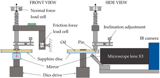
Figure 1.
Scheme of the pin-on-disc tribometer.
This pin-on-disc configuration is complemented by optical assemblies for IR thermography (see Figure 2a) and fluorescence microscopy (see Figure 2b). In both cases, the horizontal optical axis is directed into contact with the underside of the disc using an adjustable prism mirror. Temperature measurements were acquired using a FLIR SC5000 scientific-grade infrared camera (FLIR Systems, Wilsonville, OR, USA) with a 320 × 256-pixel InSb detector and two narrow-bandpass filters mounted in a filter wheel. Equipped with an X3 infrared microscope lens, the system provides a 3.2 × 2.5 mm field of view and a maximum frame rate of 380 Hz. This configuration yields a lateral sampling of 10 µm/pixel, corresponding to approximately 10 and 80 pixels across the smallest and largest dimple, respectively.
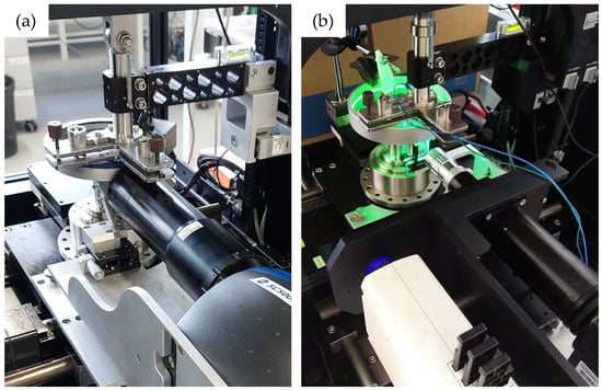
Figure 2.
A photo of the pin-on-disc tribometer with an optical assembly for (a) IR thermography and (b) fluorescence microscopy.
The fluorescence imaging system consisted of a 415 nm LED light source (Thorlabs M415L4, Thorlabs, Newton, NJ, USA), a fluorescence filter cube (comprising excitation and emission filters with a dichroic mirror), a 2× microscope objective, and a monochrome camera (Tucsen FL-20BW, Tucsen, Fuzhou, China). The camera is equipped with a 5472 × 3648 pixel cooled CMOS sensor (2.4 µm pixel size), providing a field of view of 6.55 × 4.4 mm. Excitation light was focused into the contact zone through the objective, and the emitted fluorescence was collected along the same path.
2.2. Materials
The test specimens consisted of cylindrical AISI 52100 steel pins with a flat, circular contact surface measuring 5.2 mm in diameter. Surface texturing was applied using a nanosecond-pulsed fiber laser to generate arrays of circular dimples arranged in a triangular pattern, as shown in Figure 3. This pattern ensured theoretical coverage of 19.6%, but the actual coverage varied depending on the final number of dimples on the surface of the pin. Six textured pins with the parameters summarized in Table 1 were used. Pin C and D (and E and F) had the same texture but differed in their orientation relative to the direction of disc movement. The pins were intentionally manufactured with a broad range of texture geometries to support the methodological goal of this work—namely, to demonstrate the impact of instantaneous-temperature viscosity correction on Stribeck-type trends across different texture-induced flow conditions. For this reason, the texture set includes not only a nominal 800 µm dimple design, but also a smaller-dimple geometry (Pin A) and a diagonally oriented pattern (Pin B), representing contrasting scales and orientations (including configurations that may exhibit weaker hydrodynamic benefit).
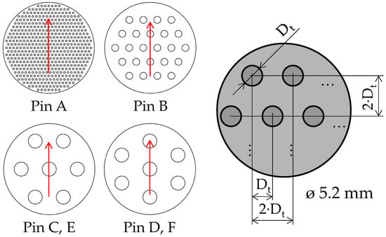
Figure 3.
Texture parameters on the pin surface (the arrows indicate oil flow direction).

Table 1.
Texture parameters on the pin surface.
Due to the limitations of laser texturing, the sides of the textures are not perfectly perpendicular, but incline approximately 40°. Before laser processing, the pin surfaces were polished to a mirror-like finish (Ra < 50 nm) to ensure uniformity. A smooth, non-textured pin was used as a reference.
The sapphire disc (synthetic single-crystal Al2O3, diameter 160 mm, thickness 5 mm) was selected for its high infrared transparency in the 3–5 μm band and its high mechanical and thermal stability. Although sapphire is not a typical industrial bearing material, transparent counterfaces (glass/sapphire) are widely used in tribology experiments when direct optical access to the lubricated contact is required. In addition to optical transparency, sapphire provides comparatively high thermal transport, of the same order of magnitude as steel.
The lubricant used in all tests was FVA4 reference oil, a mineral base oil with a kinematic viscosity of 460 mm2/s at 40 °C (ISO 3448:1992 [30]). The oil with such a high viscosity was chosen to facilitate the induction of thermal phenomena. The dynamic viscosity of the lubricant as a function of temperature was determined by Vogel’s model [31] (also known as Vogel–Fulcher–Tammann equation) in the form:
where is the dynamic viscosity of the oil in Pa·s, t is oil temperature in °C and constants A, B and C are , a . The data was adopted from literature for the reference oil [32] and was verified for the oil batch used in this study by independent measurements on a rotational Couette viscometer over the investigated temperature range. The measured viscosity values agreed with the adopted model within the experimental uncertainty.
To account for the piezoviscous behaviour of the lubricant, the dynamic viscosity was evaluated using an extended Vogel-type expression including pressure:
where p is contact pressure (bar) and constants a1, a2, b1 and b2 are , , , [32].
To measure film thickness using fluorescence microscopy, the lubricant was stained with the fluorescent dye Coumarin 6.
2.3. Methods—Infrared Thermography
A key aspect of this study is the implementation of an infrared (IR) thermography method for temperature measurement in the sliding contact. To enable separation of the radiation emitted by the steel pin and the lubricant film, two narrow-band IR filters were used in front of the camera sensor, as illustrated in Figure 4. The first filter (denoted S-filter) had a passband centered at 3.410 µm (bandwidth 290 nm) and allowed the combined infrared emission from the oil and the steel pin to be recorded. The second filter (L-filter), centered at 4.672 µm (bandwidth 140 nm), was chosen such that it predominantly transmitted radiation from the steel pin while largely excluding the oil’s emission band (since lubricating oil emits IR strongly in a narrower wavelength range around ~3.4 µm). By alternating these filters, it was possible to capture two sets of IR images: one showing the pin’s surface temperature (L-filter) primarily, and another containing both the pin’s and oil’s contributions (S-filter). Tests were also performed without any filter in the optical path to record the overall radiation as a baseline. There is also the option of measuring the temperature of the disc using a fully reflective chrome coating [18,19]; however, this approach was not used due to the wear and degradation of the coating under demanding test conditions.
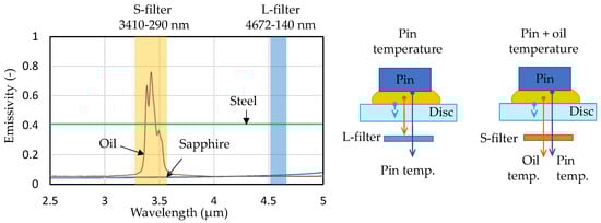
Figure 4.
The radiation spectrum of individual components, the emission filters used and a scheme of the radiation filtration of individual sources.
Because the camera measures IR intensity in arbitrary units (digital levels, DL), a thorough calibration procedure was required to convert the recorded signals into actual surface temperatures for both the steel pin and the oil film. Importantly, this approach does not attempt to determine the intrinsic emissivity of oil or steel as standalone material properties. Instead, temperature is obtained empirically by comparing the measured dual-band IR signals to a reference calibration dataset acquired under the same optical configuration and spectral bands. This reference dataset is generated in a dedicated calibration rig using a static, well-defined pin/ball–oil–sapphire configuration that is heated to a prescribed temperature, thereby reproducing the relevant radiometric conditions (emission, reflections, and transmission through the lubricant layer) in a controlled manner. In other words, the calibration establishes a direct mapping between DL (in each band) and temperature for the specific lubricant and surface state, including the effect of a defined lubricant gap. The calibration was an extended, multi-step process that built upon a method previously developed for point contact (ball-on-disc) measurements [33]. In adapting it to the present conformal contact, three main calibration steps were performed to account for the different radiation sources and the presence of a lubricant layer, as shown schematically in Figure 5:
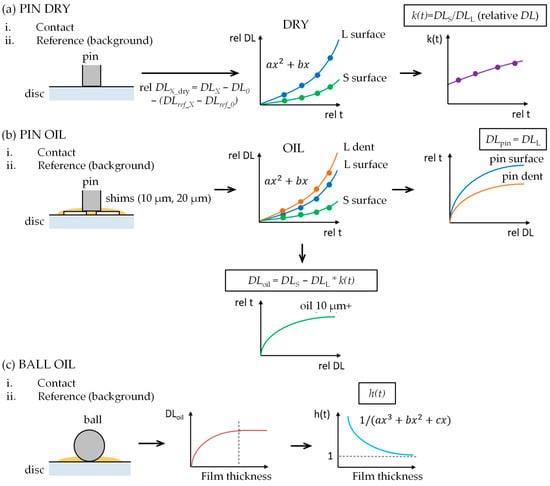
Figure 5.
Scheme of the calibration procedure for the IR thermography: (a) Calibration using a flat pin under dry conditions; (b) Calibration using a flat pin with oil, and (c) Calibration using a ball and oil.
- (a)
- Dry calibration with a pin: First, the steel pin’s surface emission was calibrated in a dry state. The calibration test rig consisted of cartridge heaters and thermocouples, which were used to precisely regulate the temperature of the steel sample via a controller. In the dry calibration, the pin (with no oil) was heated stepwise from room temperature up to about 100 °C, and at each plateau the IR camera recorded images through both the L-filter and S-filter. Since no lubricant was present, the L-filter images captured the pin’s thermal radiation directly, and the S-filter images captured the same pin radiation but through the other filter. From each pair of images at a given temperature, a filter transmittance factor k(t) was determined to account for the different spectral responses of the two filters. In practice, the raw digital levels from the camera were first fitted as functions of the known temperature (using a quadratic polynomial fit), and then k(t) was obtained from the ratio DLS/DLL at each temperature. This step established the relationship between IR intensity and actual temperature for the steel pin surface for both filter configurations.
- (b)
- Oil calibration with a pin: The second step introduced a thin layer of oil between the pin and the sapphire disc to calibrate the measurement of lubricant film temperature. Thin metal shims of known thickness (10 µm and 20 µm) were placed under the pin in the calibration fixture to create a controlled oil-filled gap. At each temperature plateau, IR images were recorded with the L-filter and S-filter. Due to the different reflectivity of the surfaces, L and S-filter data were evaluated on both the smooth surface and at the bottom of the dimple. From the L-filter data, digital level values were obtained for the pin surface (smooth area) and the pin dimple. The S-filter data for the smooth surface area provides the combined signal of steel and oil. Using the previously determined k(t) to account for filter differences, the oil film’s contribution at each temperature could be isolated by subtracting the appropriately scaled steel signal from the S-filter measurement. This yielded a calibration curve of IR intensity vs. temperature for the lubricant oil film in a thin layer.
- (c)
- Oil calibration with a ball: The third calibration step was designed to account for the effect of oil film thickness on the measured IR intensity. A steel ball and the sapphire disc were used to create a continuously varying gap. By pressing a steel ball against the sapphire disc with a layer of oil and heating it to a known elevated temperature, a single camera image can capture regions of different film thickness (from the center of contact outwards). The geometry of the ball-on-disc contact was determined using Hertzian contact theory calibrated by an interferometric method [34], so that at each pixel in the IR image the local oil film thickness was known. Based on a relation between the oil’s IR signal (DLoil) and the film thickness h, a thickness compensation factor h(t) was introduced. The calibration confirmed that beyond a certain thickness (~10 µm for the FVA4 oil), the recorded IR intensity from the oil stops increasing (the oil layer becomes optically thick, contributing its full black-body emission). So, for oil layers thicker than about 10 µm, h(t) = 1 (no correction needed), while for thinner films, h(t) < 1, proportionally reducing the inferred temperature to account for the reduced emission.
2.4. Methods—Fluorescence Microscopy
Lubricant film thickness was evaluated using fluorescence microscopy, a technique that correlates optical intensity with local film thickness. To ensure reliable thickness evaluation, a multi-step calibration procedure was carried out prior to testing (see Figure 6) [35]. The first step involved flat-field correction to eliminate non-uniformities in the illumination field and sensor response. This was performed using a calibration fixture holding a smooth glass pad and 10 µm-thick spacer shims to create a uniform oil layer of known thickness. Flat-field correction was applied directly in the acquisition software(Micro-Manager v2.0.0).
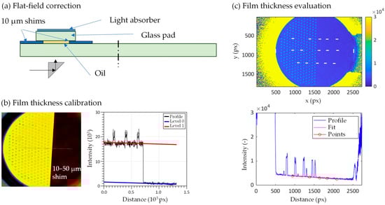
Figure 6.
Scheme of the calibration and evaluation procedure for the fluorescence microscopy: (a) Flat-field correction, (b) Film thickness calibration and (c) Film thickness evaluation.
To assign absolute film thickness values to fluorescence intensities, a secondary calibration was performed using spacers (10–50 μm thick shims) partially inserted into the contact zone between the pin and the disc. Cross-sectional profiles of the fluorescence image were extracted across this interface. Linear fits to the shim region and the adjacent pin surface were used to calculate the optical gap.
Lubricant film thickness evaluation was performed in three independent profiles, which were evaluated and averaged. The film thickness distribution is evaluated by comparison with the calibration curve. By fitting the film thickness in a smooth area (outside the pits), the actual inclination of the pin is further determined. This allows precise alignment and determination of the instantaneous inclination during the test.
2.5. Experimental Procedure and Parameters
The aim of this study was to investigate thermal effects; therefore, the test procedure and operating conditions were selected to promote a measurable temperature rise. Stribeck-type curves were constructed by plotting the coefficient of friction as a function of a modified Hersey parameter ηu/F, where η is the dynamic viscosity, u the sliding speed and F the applied normal load (Also referred to as the “characteristic number” in this work). For each load, the rotational speed was increased stepwise from 50 to 1400 rpm, corresponding to sliding speeds from 0.3 to 8.1 m/s. At each speed setpoint, the disc ran for a short duration (4 s) under steady conditions while data were recorded, and then the rotation was stopped for a cooling period of 10–40 s before the next speed step. This start-stop cyclic approach (illustrated schematically in Figure 7) ensured that a temperature rise in the contact was mostly due to the immediate frictional heating at that speed, rather than cumulative bulk heating from the previous steps. The pause allowed the contact to return closer to ambient temperature before each new speed, improving the repeatability of measurements and preventing excessive thermal drift. Four normal loads were used: 5 N, 10 N, 20 N, and 50 N, corresponding to nominal contact pressures (assuming the flat-on-flat apparent contact area of the pin) of approximately 0.2, 0.5, 0.9, and 2.4 MPa, respectively.
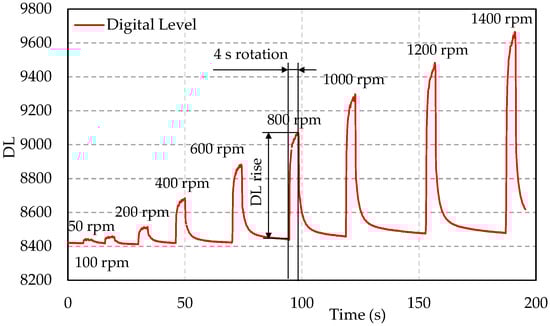
Figure 7.
Evolution of the IR camera digital level (DL) in the Stribeck curve measurement cycle for one load, including 4 s rotation periods and cooling periods.
All experiments were conducted under conditions corresponding to the hydrodynamic lubrication regime (full-film separation), as characterized by the applied range of ηu/F. Consequently, the term “Stribeck curve” is used here to denote only its hydrodynamic regime (hydrodynamic branch) rather than the full boundary–mixed–hydrodynamic transition.
The tests were conducted in two pin inclinations: 0.05 degrees representing the wedge gap and 0 degrees representing the parallel surfaces.
Each test sequence (covering all speeds for a given load) was conducted four times:
- •
- IR optical setup with L-filter;
- •
- IR optical setup with S-filter;
- •
- IR optical setup with no filter;
- •
- Fluorescence optical setup for lubricant film thickness measurement.
Before each measurement, a reference image of the static contact was taken to be subtracted as a “background” for temperature evaluation, and a flat-field correction was made for fluorescence imaging. This procedure was time-consuming and required strict adherence to test conditions, but it enabled the application of a robust temperature distribution evaluation.
Using the established calibration curves, the relative increase in temperature of the oil and the pin surface was obtained for each step. The maximum temperature in the contact typically occurred at the end of the 4 s running period, and this was taken as the representative contact temperature for that speed and load. Because of a limited field-of-view of the IR optical system, the view is directed toward the center of the pin. In addition to the temperature obtained by filtering individual radiation sources, an “average temperature” is also evaluated, which is determined based on measurements and calibrations without the filters. The experimental data are then used to construct Stribeck curves (COF vs. a velocity or viscosity-speed parameter) for each tested pin and condition.
3. Results
3.1. Temperature Measurement
Typical examples of the temperature field obtained from the infrared thermography setup are shown in Figure 8. The left image represents the surface temperature of the pin, while the right image shows the temperature of the lubricant film. It should be noted that the pin temperature map is composed of two separately calibrated regions: the flat surface outside the dimples (“Pin–flat”) and the dimple interiors (“Pin–dimple”). For further analysis, the temperature values are evaluated over two regions of interest: (i) an area corresponding to a single dimple and (ii) an annular region surrounding the dimple in the central part of the pin. The temperature differences between the dimple and flat regions are apparent, especially for the pin temperature. The oil temperature exhibits much higher noise, which is a consequence of the calibration procedure: after subtracting the L-filter signal, the remaining oil contribution corresponds to only a small range of digital levels.
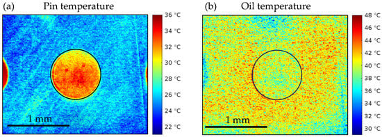
Figure 8.
Typical temperature fields of the pin surface and lubricant film obtained by infrared thermography for Pin E (800 × 10 µm dimples in a diagonal arrangement) at 50 N and 8.1 m/s: (a) Pin surface temperature and (b) Oil temperature.
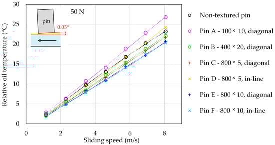
Figure 9 summarizes the relative temperature rise as a function of sliding speed for the large-dimple pin E (800 × 10 µm dimples) at the highest load of 50 N for both parallel and inclined (0.05°) contacts. Relative temperature is defined as the increase in temperature with respect to the initial reference temperature of the oil in a bath. In both contact geometries, the temperature of the lubricant and of the pin increases almost linearly with sliding speed, which is well captured by a second-order polynomial fit. The lubricant temperature is systematically higher than the temperature of the pin surface, confirming that shear heating in the oil film is the dominant source of heat generation. Within the pin, the temperature in the dimple region is slightly higher than on the surrounding flat area, indicating a modest local intensification of shear and/or reduced heat dissipation inside the texture. For the oil, the difference between the dimple and flat regions is present but less pronounced. The “average” temperature measured without spectral filtering is significantly lower than both the oil and pin temperatures; this confirms that unfiltered thermography underestimates the actual fluid and surface temperatures in the contact zone. Parallel contacts exhibit higher overall temperatures than inclined contacts, which is consistent with the higher coefficients of friction observed in the parallel configuration.
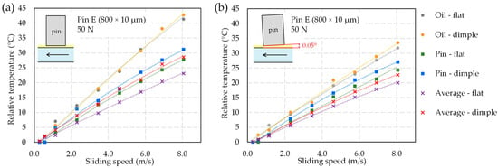
Figure 9.
Relative pin and oil temperatures in the dimple and flat regions as a function of sliding speed for pin E at 50 N in (a) parallel and (b) inclined (0.05°) contacts.
3.2. Friction Measurement
The coefficient of friction (COF) was analyzed as a function of the combined parameter, including sliding speed u (m/s), lubricant viscosity η (Pa∙s), and applied normal force F (N). Figure 10 illustrates the influence of different viscosity-correction approaches on the Stribeck curve for a parallel contact with pin C (800 × 5 µm). When viscosity is calculated at a fixed reference temperature (a thermocouple in the oil bath, approximately room temperature, see Figure 10a), the COF data deviate markedly from the expected power-law trend, especially at higher loads and speeds. Using the “average” temperature from unfiltered IR measurements (Figure 10b) partially reduces this deviation, but significant scatter remains, and the points still deviate from a single master curve as the temperature increases.
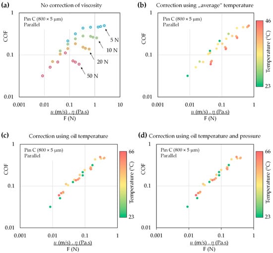
Figure 10.
Effect of different viscosity corrections on the Stribeck behaviour for the parallel configuration with pin C (800 × 5 µm): (a) No correction of viscosity, (b) Correction using “average” temperature, (c) Correction using oil temperature and (d) Correction using oil temperature and pressure, showing that only the correction based on instantaneous oil temperature collapses the data onto a single trend.
The most consistent behaviour is obtained when viscosity is corrected using the instantaneous oil temperature (Figure 10d). For the viscosity correction, a single representative in-contact oil temperature was used, evaluated as the mean value within a central area between dimples. In this case, the data collapse onto a nearly single power-law trend over the whole range of loads and speeds, independent of the local operating temperature. This confirms that the apparent non-linearity in the uncorrected Stribeck curves is largely a consequence of temperature-induced variations in viscosity, rather than changes in the lubrication regime.
In addition to the temperature-based viscosity correction, the pressure–viscosity dependence was also evaluated using the nominal contact pressure, as summarized in Figure 10d. The comparison indicates that the pressure contribution has a negligible effect on the corrected friction trends across most operating conditions. A measurable influence is observed only under the highest load at the lowest temperatures, where the pressure–viscosity term produces a slight upward shift in the corrected COF (i.e., a minor change along the y-direction). Overall, the correction confirms that the experimentally observed scatter and alignment of the Stribeck-type curves are governed primarily by the temperature–viscosity effect, whereas pressure–viscosity coupling plays a secondary role within the present operating window.
When the correction using in-contact oil temperature is applied, data for all pins and both contact geometries can be plotted together, as shown in Figure 10. In the parallel configuration (Figure 11a), all textured pins and the smooth reference pin fall within a relatively narrow band, with only modest differences between the texture designs. The inclined configuration (0.05°, Figure 11b) yields generally lower COF values and a tighter alignment of points along the power-law trend, indicating more stable hydrodynamic lubrication due to the controlled wedge angle.
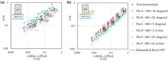
Figure 11.
Stribeck-type curves (COF vs. modified Hersey parameter) for the tested pins under (a) parallel and (b) inclined contacts. For inclined contact (b), the solid line shows a classical hydrodynamic reference for a fixed-incline slider bearing according to Raimondi and Boyd [36], evaluated for an equivalent pad geometry (L = 5.2 mm, B = 4.1 mm; L/B = 0.785) using viscosity corrected by the experimentally measured in-contact oil temperature.
To provide a first-order hydrodynamic benchmark, Figure 11b was complemented with a reference COF trend obtained from the classical fixed-incline slider-bearing charts of Raimondi and Boyd [36]. An equivalent rectangular pad geometry was assumed, with the pad length set to the pin diameter (L = 5.2 mm) and the pad width derived from the projected contact area (B = 4.1 mm), resulting in an L/B ratio of 0.785. The bearing characteristic number (Kf) was evaluated using the lubricant viscosity corrected by the instantaneous in-contact oil temperature measured experimentally, and the corresponding friction coefficient was obtained from the published charts. Because the chart coverage does not fully span the complete experimental range, the reference curve was extrapolated accordingly. The comparison indicates that the Raimondi–Boyd prediction reproduces the overall increase in COF with increasing characteristic number but remains systematically lower than the measured values.
Figure 12 shows the same corrected friction data, colored by the oil temperature. This representation highlights that a wide range of contact temperatures (from ~23 °C to over 60–70 °C) leads to very similar COF when viscosity is properly corrected, further underlining the importance and effectiveness of the temperature-based correction.
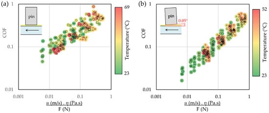
Figure 12.
Stribeck curves corrected using in-contact oil temperature for all texture patterns in (a) parallel and (b) inclined (0.05°) contacts (same as in Figure 11), with data points colored by oil temperature in the contact.
To quantify the influence of individual textures on friction and to evaluate the impact of the viscosity correction based on the instantaneous in-contact temperature, a two-step comparison is performed (Figure 13, inclined contact). For the uncorrected dataset, the relative change in COF with respect to the smooth reference pin is computed at each value of the characteristic number (identical for all pins) and then averaged over the range covered in this study. For the viscosity-corrected dataset, COF for each pin is obtained from the power-law relationships derived from the fits in Figure 11b, evaluated over the same range of the uncorrected characteristic number, and then averaged.
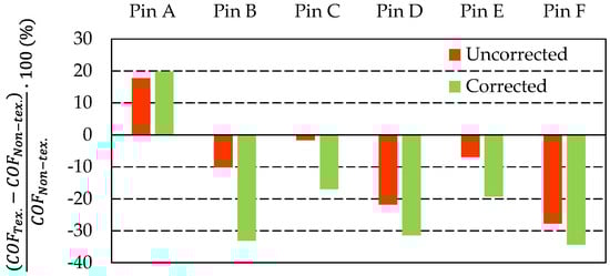
Figure 13.
Relative change in the coefficient of friction (COF) of textured pins A–F with respect to the smooth reference pin for the inclined contact. “Uncorrected” values are averaged from the measured COF at identical values of the characteristic number. “Corrected” values are obtained from the power-law fits in Figure 10b, evaluated over the same characteristic-number range, and then averaged.
Figure 13 shows that the viscosity correction increases the separation between the individual textures. In the inclined configuration, pins B, D, and F exhibit the largest improvement, with a COF reduction exceeding 30% relative to the smooth pin. Pins C and E also reduce friction, although to a smaller extent. The only texture that consistently increases friction is pin A, which features the smallest diameter of the dimples. For parallel surfaces, the ranking of texture patterns differs, likely due to the stronger influence of cavitation and unsteady conditions in nominally parallel gaps. Overall, texturing yields a systematic reduction in friction compared with the smooth reference; in the inclined configuration, this reduction becomes more pronounced after viscosity correction, whereas in the parallel configuration, the texture effect remains more moderate and is more sensitive to unsteady film behavior.
3.3. Lubricant Film Thickness Measurement
The lubricant film thickness was measured by fluorescence microscopy and evaluated as a function of the same combined parameter on the y-axis. Figure 14 shows results for pin C (800 × 5 µm) for both parallel and inclined contacts, with points colored by oil temperature.
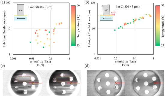
Figure 14.
Lubricant film thickness as a function of the combined parameter for pin C (800 × 5 µm) in (a) parallel and (b) inclined (0.05°) contacts, together with typical intensity maps from fluorescence imaging for (c) parallel and (d) inclined contacts, showing cavitation in parallel contacts (the arrows indicate lubricant flow).
In the parallel configuration, the film thickness exhibits a large scatter and frequently falls below 10 µm. This regime is susceptible to small variations in alignment and to dynamic effects, such as disc run-out, which can lead to intermittent thinning and local rupture of the film. The scatter is further enhanced by cavitation between individual dimples, resulting in rapid changes in oil film thickness, as illustrated by the intensity maps from fluorescence imaging in Figure 14c. Therefore, there is no clear correlation between film thickness and the combined parameter, and the data does not fit a clear trend in the same way as the friction data after viscosity correction.
In the inclined configuration, the lubricant film thickness remains consistently above 10 µm over most of the measured range and increases moderately with the increasing characteristic number. This indicates robust full-film hydrodynamic lubrication in the wedge contact.
3.4. Local Effects
One of the study’s aims was to investigate the local thermal effects occurring in dimples. It was found that some “local effects” can be observed in dimples using IR thermography; however, these are more likely to be the result of local changes in film thickness rather than local temperature changes. Some examples are shown in Figure 15, highlighting the complexity of the problem. The following interpretation is based on high-speed IR observation of the contact, which enabled the estimation of lubricant flow in the dimples.
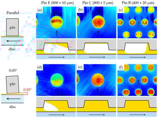
Figure 15.
IR images showing local phenomena associated with cavitation in dimples for different pins and contact configurations; the arrows indicate the lubricant flow direction: (a) Pin E, parallel, (b) Pin C, parallel, (c) Pin B, parallel, (d) Pin E, inclined, (e) Pin C, inclined, (f) Pin B, inclined.
In the parallel configuration, cavitation occurred frequently. Figure 15a shows cavitation in and behind the dimple, while a part of the dimple is filled with lubricant. The inclined oil layer creates interference fringes even in the case of an IR optical system. In Figure 15b, cavitation occurs in the same way, but there is no longer any lubricant in the cavity. For the smaller dimples in Figure 15c, partial cavitation occurs in some lines of dimples. For the wedge-gaped contacts, cavitation usually occurs only in the dimples. In Figure 15d, interference fringes are visible within the cavitated region, indicating a thin residual film of lubricant trapped at the dimple bottom and a locally varying film thickness. Figure 15e,f depict contacts without cavitation in the dimples, corresponding to conditions with more stable lubrication. It should be noted that the annular elements in the dimples in Figure 15f correspond to the actual shape of the pit bottom, which is not completely smooth.
4. Discussion
4.1. Temperature Distribution in Textured Contacts
Infrared measurements in this study consistently revealed elevated lubricant and pin surface temperatures inside micro-dimples compared to surrounding smooth areas. This observation aligns with prior numerical and experimental studies that demonstrate texture-induced non-uniformities in both flow and thermal fields [9,29,37]. Despite the locally increased film thickness, the dimples exhibited higher temperatures, suggesting that surface geometry significantly modulates local hydrodynamics and heat generation mechanisms.
Temperature distribution in lubricated contacts is governed by the interplay of viscous dissipation, thermal conduction, and convective transport within the fluid. One key aspect is the partition of frictional heat between the lubricant and the solid surfaces. In fully hydrodynamic conditions, most frictional energy is dissipated as heat in the lubricant due to viscous shear. The exact distribution of heat depends on material thermal properties and operating conditions: a fast-sliding, thermally insulating interface will drive more heat into the fluid, whereas highly conductive surfaces or slower speeds allow greater heat conduction into the solids. In our experiments, energy dissipation occurred primarily within the lubricant due to viscous shear. The lubricant consistently reached higher temperatures than the steel surface, which can be attributed to the exceptionally high viscosity of the oil and its lower thermal conductivity compared to contacting bodies.
The degree of thermal coupling between the lubricant, solid surface, and induced flow structures depends strongly on the texture geometry and the operating regime. Shallow dimples tend to concentrate shear near the moving surface, locally heating the fluid adjacent to that surface more intensely. Similarly, very deep or large textures might induce regions of disturbed flow or even intermittent contact, potentially introducing solid friction heating under heavy load. On the other hand, deeper or larger dimples promote recirculation and mixing, which spread heat more uniformly through the film. A trapped vortex means the fluid is sheared for a longer time, accumulating heat in a pocket and increasing its temperature. This phenomenon has been confirmed numerically [9] and experimentally [29], where dimples exhibit localized temperature rises due to shear within stagnating vortices. However, other texture geometries—especially grooves—can induce oil flow in textures and enhance convective cooling, thereby reducing the temperature rise [26].
In our experiments, no direct correlation was found between dimple geometry and friction reduction beyond the temperature-corrected viscosity effect. However, the significant local temperature rise observed inside dimples suggests that microflow–temperature coupling may exist. The thermal field can be further affected by local shear, the slip condition at the oil-surface interface [28] and non-Newtonian lubricant behaviour (e.g., shear-thinning [38]). In-texture cavitation also plays an important role, which is discussed in a separate chapter. The viscosity-corrected friction trends retained a near-power-law form, indicating that, under current conditions, temperature-induced viscosity changes predominate over secondary thermohydrodynamic phenomena.
4.2. Temperature-Based Viscosity Correction
To account for thermal effects on viscosity, the instantaneous oil-film temperature in each test point was used. This differs from some prior approaches that relied on indirect measurements, e.g., [27] monitored journal bearing temperature with an embedded thermocouple in the housing and assumed it represented the film temperature. By contrast, our infrared method measures the local lubricant temperature in situ, capturing transient and spatial variations. In practice, using the local oil temperature yields a more direct estimate of the oil viscosity than measurements taken from the side or housing. However, the IR technique requires careful calibration and access through an optical window, whereas a thermocouple is simpler and robust.
By comparing the filtration method based on instantaneous lubricant temperature and the “average IR” temperature, oil temperature compensation proves to be more accurate, as shown in Figure 10 for parallel contacts. When the contact conditions are less severe in terms of temperature and friction power, compensation using the average instantaneous contact temperature also provides reasonable results, and this measurement method is much simpler than using two narrow-band filters.
The present temperature-based correction explicitly accounts for the temperature dependence of viscosity, as viscosity is the property that most directly governs hydrodynamic shear stress and film formation, and it is also the key parameter appearing in the modified Hersey/characteristic number used for normalization. Other temperature-dependent properties (density, thermal conductivity, heat capacity) and potential non-Newtonian behavior were not parameterized in the correction. Their primary impact in the present experiments is through the resulting temperature field and heat partitioning; this influence is already reflected in the measured local oil-film temperature that is used to evaluate the instantaneous viscosity. In addition, available data indicate that the temperature dependence of lubricant thermal conductivity is often relatively weak compared to other effects (e.g., pressure), suggesting a secondary role in many operating ranges [39,40]. Finally, numerical analyses of thermal wedge mechanisms report that the thermal density-wedge contribution is negligible compared to the thermo-viscous (viscosity-wedge) effect, supporting viscosity as the dominant temperature-sensitive property for first-order normalization [12]. A quantitative separation of second-order couplings would require a robust coupled THD numerical framework; therefore, the present work focuses on experimentally robust interfacial temperature mapping and viscosity-based normalization as the most physically justified first-order correction.
The observed offset between the hydrodynamic chart prediction and the experiment is not unexpected, as the Raimondi–Boyd solution [36] represents an idealized fixed-incline rectangular slider bearing under isoviscous, steady, fully flooded assumptions and with simplified boundary conditions. In contrast, the present contact is defined by a circular pin footprint on a rotating disc, and the “equivalent” rectangular dimensions only approximate the actual flow domain and edge leakage paths. This geometric mismatch affects side leakage and pressure–shear partitioning, and can lead to systematic differences in predicted friction.
Additional contributors to the deviation include effects not captured by the chart-based model: (i) non-uniform thermal fields and cross-film temperature gradients (non-isoviscous behavior) even when viscosity is evaluated from the measured instantaneous oil temperature, (ii) inlet/outlet boundary conditions that may deviate from fully flooded operations (local starvation or recirculation on the rotating disc), (iii) unsteady cavitation/film rupture events that alter the effective shear area, and (iv) sensitivity to extrapolation of the chart data outside the original parameter range. Therefore, the Raimondi–Boyd curve should be interpreted as a baseline hydrodynamic reference, demonstrating that the measured trends are consistent with classical hydrodynamic scaling. The remaining offset, however, motivates more application-specific modeling (e.g., Reynolds/THD solutions for the actual circular footprint and thermal boundary conditions) in future work.
4.3. Coupling Mechanisms in Textured Thermo-Hydrodynamic Contacts
The coupling between transient local temperature rise and lubricant properties (primarily viscosity) is a key feedback mechanism influencing friction in lubricated contacts.
This thermal–viscous interaction alters the local film thickness and, by extension, the friction coefficient. Under the tested hydrodynamic conditions, this coupling manifested predominantly as a continuous trend along a power-law slope in the feedback loop: frictional dissipation→local temperature increase→viscosity drop (and slight density drop)→altered hydrodynamic balance→changed pressure distribution and film thickness. In the hydrodynamic regime, this thermal-viscous feedback can be self-limiting.
The current results show that different surface textures led to different equilibrium oil temperatures during tests—textures that generated higher frictional dissipation warmed the oil more, further lowering its viscosity and, in some cases, somewhat mitigating their own friction (a self-correcting effect). By contrast, textures that inherently reduced friction (through hydrodynamic effects) caused less heating, so the oil remained more viscous, slightly counteracting the friction reduction. In textured contacts, these temperature variations are often local—e.g., a hot spot inside a dimple lowers the viscosity there, which could either locally reduce shear stress or, if it occurs primarily near the moving surface, potentially contribute to a micro-scale viscosity wedge that lifts the load.
Thermal expansion of the solid surfaces can locally alter film thickness by creating a “thermal wedge” effect—i.e., a localized distortion of the surface geometry due to temperature gradients. A hotspot near the trailing edge of a texture may increase clearance, while one near the inlet may reduce it. Although such effects are well-documented in mechanical seals [41], they are likely negligible in our study due to the small texture size and modest temperature rise. However, under higher loads or prolonged heating, thermo-elastic feedback could become significant.
Although this study focused on the hydrodynamic regime, thermal–fluid–solid coupling may behave differently in other lubrication regimes. In mixed lubrication, where film thickness decreases and asperity interactions emerge, local frictional heating may have a stronger impact on viscosity and pressure development [42]. In boundary lubrication, friction is largely governed by surface properties, but flash temperatures at contact spots can still influence lubricant rheology. The present infrared and viscosity-correction methodology may be extended to such regimes in future work, provided film stability and surface sensitivity are addressed.
4.4. Effect of Surface Texturing Parameters
The primary objective of this study was not to optimize texture parameters for a specific operating point, but to demonstrate how instantaneous temperature-based viscosity correction affects the interpretation of friction trends for textures of different scales. Relatively large dimples were selected to enable robust IR evaluation and to facilitate observation of local phenomena. They are also consistent with thermo-hydrodynamic optimization trends reported by Meng and Khonsari [9,10]. Their THD analyses of dimpled parallel sliders recommend dimensionless dimple depth Hg = hg/h0 around 0.6 for maximum load-carrying contribution and Hg ≈ 1.0 for minimum COF, and they recommend dimple area ratio S < 25% to avoid deterioration of the viscosity-wedge contribution. Our textures have coverage ~14–17%, i.e., within the recommended range, and the selected depths (5 and 10 μm for the 800 μm dimples) were chosen to bracket the Hg ∼ 0.5–1 H range for the characteristic film thicknesses measured in our wedge configuration (typically > 10 μm).
Despite the non-optimized texture design, most textures reduced friction relative to the smooth reference, with the best-performing textures achieving a reduction of ~30% compared to the smooth pin in the inclined configuration (Figure 12). The correction generally increases the separation between textures and can change their ranking because the uncorrected comparison mixes the intrinsic texture effect with temperature–viscosity feedback: different textures produce different thermal responses, altering the effective viscosity during the test. This is illustrated in Figure 16, which shows a correlation between COF and the oil temperature used for correcting the inclined contact. Applying the temperature–viscosity correction shifts data toward lower characteristic numbers because the effective viscosity decreases with increasing in-contact oil temperature. This correlation suggests that higher oil temperatures are primarily a consequence of increased frictional dissipation (pin A and non-textured pin).
The effect of texturing should not be interpreted as a shift in the lubrication regime. However, the textures still modify the hydrodynamic flow field and film-thickness distribution in a geometry-dependent manner. In the present full-film regime, friction is primarily viscous; therefore, differences can arise from (i) changes in the effective shear rate due to local film-thickness modulation, (ii) micro-hydrodynamic pressure perturbations around dimples (which can slightly change the mean separation), and (iii) additional dissipation associated with recirculation/mixing inside cavities.
A strict one-to-one correlation with a single geometric parameter (areal coverage, depth, diameter, or orientation) cannot be claimed because these parameters are not varied independently across the pin set. Nevertheless, the observed ranking for inclined contact is consistent with the following qualitative trends: the smallest dimples (Pin A) provide little hydrodynamic benefit and can even increase COF, likely because the cavity volume is insufficient to generate a meaningful local film-thickness/pressure effect while still disturbing the near-wall shear field. In contrast, textures with a larger characteristic scale and/or more favorable orientation with respect to the main flow direction can promote smoother entrainment and a slightly thicker effective film, leading to a systematically lower COF. Conversely, overly large/deep features may increase losses through stronger recirculation and unsteady two-phase behaviour in nominally parallel gaps, which can offset the benefit—consistent with the configuration-dependent ranking observed in the data.
The question is how much of this benefit comes from purely geometric hydrodynamic effects (i.e., the textures generating additional lubricant film pressure or reducing shear by altering flow geometry) versus thermal effects (the textures causing local heating or changes in lubricant state that reduce friction). It is likely that, under the tested conditions, the majority of the friction reduction is geometric/hydrodynamic in nature, with a smaller fraction attributable to thermal feedback; however, there may be a synergistic interplay between the two.
4.5. Local Thermal Effects
This work hypothesizes that the thermal effects could be “quantitative”, where the relation between friction and temperature lies simply in a change in viscosity, and “qualitative”, causing other significant variations in friction, lubricant film thickness and load-carrying capacity. Since the viscosity-corrected Stribeck curves in Figure 11 and Figure 12 retain a near power-law form, the dominant thermal contribution in the present dataset appears to be the temperature-driven viscosity reduction (“quantitative” effect). Within the resolution and scatter of the present experiments, we did not identify additional thermal mechanisms that would systematically alter the slope or shape of the viscosity-corrected trend. However, more subtle thermohydrodynamic contributions (e.g., viscosity- or density-wedge action) may still exist and become detectable under more favorable operating and thermal boundary conditions.
Numerical work suggests that the thermal/viscosity-wedge contribution is most likely to become detectable in nearly parallel gaps when a sufficiently large cross-film temperature gradient is sustained by the operating and thermal boundary conditions. For a nominally parallel gap of ℎ0 ≈ 20 μm, Cui et al. [12] predicted a monotonic increase in load support with sliding speed, yet also showed that the sign and magnitude depend strongly on boundary conditions; for boundary conditions representative of typical metallic contacts, a clearly positive net effect emerges only at higher speeds (order >25 m/s). In micro-textured parallel-surface simulations, Meng and Khonsari [9] similarly reported that the viscosity-wedge influence is weak at a low Reynolds number, and becomes pronounced only when the combination of high speed (tens of m/s), small film thickness (order 5–20 μm), and thermal boundary conditions promotes strong shear heating and a temperature gradient across the film.
In the present experiments, the speed range (0.3–8.1 m/s) and the stable wedge configuration (film thickness mostly >10 μm) are therefore expected to yield only a modest viscosity-wedge contribution relative to the dominant geometric wedge. Further increasing the sliding speed in the current pin-on-disc configuration is challenging due to the dynamic unsteady conditions and centrifugal forces acting on the lubricant layer on top of the disc. Conducting experiments in a parallel configuration, on the other hand, poses challenges related to unstable cavitation, as discussed in the following chapter.
Regarding the texture geometry, a local thermal wedge effect may arise if a particular texture creates a hot spot in the lubricant, which then influences the film shape or pressure. The likelihood of this depends on both texture parameters and operating conditions. Numerical studies [9,10] indicate that a pronounced viscosity-wedge effect in textured parallel contacts emerges when the texture depth-to-film thickness ratio is optimized (Hg/h0 ≈ 0.6) and the area density is low (S < 25%), thereby minimizing cavitation. The effect becomes more significant at high values of the dimensionless bearing number (Λ > 1000), i.e., at higher speed, higher viscosity, and smaller film thickness. In the current study, the combination of high oil viscosity, modest temperature gradients, and the presence of unsteady cavitation likely suppressed the development of a strong viscosity-wedge effect, although its contribution cannot be entirely excluded.
Overall, the present parameter space did not yield an unambiguous experimental signature of viscosity- or thermal-wedge action beyond the dominant viscosity reduction captured by the in situ oil-temperature correction. This does not contradict prior numerical predictions; rather, it highlights the strong sensitivity of the effect to thermal boundary conditions and to the stability of the film in nominally parallel gaps. For example, Cui et al. [12] predict an increasing load-carrying contribution with sliding speed already in the single-digit m/s range, with the strongest response obtained under “adiabatic” boundary conditions that sustain a pronounced cross-film temperature gradient. In our experiments, the near-parallel configuration was frequently affected by cavitation and film-thickness fluctuations, which can mask small, wedge-driven thermal asymmetries. In contrast, the inclined configuration provided more stable full-film lubrication but smaller temperature gradients. Therefore, targeted experiments with boundary conditions optimized for stable gradients (e.g., the use of a thermally insulating coating on the pin surface) are a logical next step, enabled by the present IR methodology.
4.6. Cavitation-Related Effects
Cavitation can enhance hydrodynamic pressure generation in parallel-textured contacts via inlet suction and entrainment mechanisms [43]. Under certain conditions, expanding vapor zones near the inlet of micro-dimples can generate a localized pressure drop, promoting lubricant entrainment and effectively increasing film thickness and load-carrying capacity. In the present study, cavitation occurred only occasionally in inclined contacts (Figure 14d), where it remained localized to the outlet side of dimples and exhibited a relatively stable shape. In parallel contacts (Figure 14c), cavitation was observed extensively in the whole contact area. Instead of increasing load capacity, it appears to destabilize the film by disrupting the flow continuity, especially in the outflow region of dimples, where vapor pockets intermittently break the fluid film. These cavitation zones changed dynamically over time, reflecting the inherent instability of real pin-on-disc experiments with nominally parallel geometries.
Cavitation can have a significant impact on heat distribution in textured contacts. Within cavitated regions, the absence of liquid lubricant disrupts viscous shear heating and alters thermal conduction pathways. Although the vapor phase itself carries little heat, it acts as a thermal insulator between the surface and the fluid. Due to the low thermal conductivity of a gas, localized hotspots form near the gas–liquid interface, as observed in infrared studies and simulations [10,26,37,43].
In experiments using infrared microscopy, cavitation also affects temperature detection. The coexistence of gas and liquid made the overall temperature distribution more heterogeneous—some points were “cold” (air) and others “warm” (oil), increasing the spatial temperature differences. If only the “overall” temperature is measured, this leads to an underestimation of the lubricant temperature [26]. However, this masking mechanism does not apply in our study, as we utilize dual filtering of the IR signal. In the spectral bands used (3–5 µm), air exhibits nearly full transmissivity, meaning that a vapor-filled gap transmits IR radiation from the underlying oil or solid surface with minimal attenuation.
The greater challenge of the current dual-filter IR method lies in the non-stationary nature of cavitation zones in nominally parallel contacts. Because the cavitation pattern changes dynamically during rotation, it is not possible to acquire synchronized multi-filter IR images or film-thickness readings under identical conditions. As a result, cavitated regions were excluded from all quantitative temperature evaluations in this study, and only stable, liquid-filled zones were considered for thermal analysis.
4.7. IR Thermography Strengths and Limitations
The infrared thermography technique offers significant advantages for studying lubricated contacts. It is non-contact and spatially resolved, providing full maps of temperature on both the oil film and the surfaces. Importantly, the distinction between lubricant-film and solid-surface temperatures is not achieved by geometric depth resolution across the film thickness, but rather by a radiometric separation using the calibrated dual-band method and lubricant- and surface-specific calibration functions. Thus, resolving small oil–surface temperature differences is primarily limited by radiometric sensitivity and calibration uncertainty rather than by pixel size.
This in situ imaging is valuable for validating thermal models. The trade-off is that IR measurements are complex: each test requires careful calibration and a sequence of measurements that cannot be performed consecutively within a single test due to constantly increasing temperatures or the need to replace the optical system. Compared to established procedures used in point contacts, the examined system is more complex and introduces several challenges. Attention must be given to calibration accuracy, as conformal contacts typically show lower “flash” temperatures. At these lower temperatures, the method faces limitations—especially when optical filters are used—because the signal captured by the camera sensor is weaker, making it difficult to reliably evaluate small temperature changes.
A meaningful simplification may be to evaluate only the “average” temperature, where optical filters are not used, but at the cost of not being able to distinguish between radiation sources. To compensate solely for viscosity based on instantaneous temperature, this approach may be sufficiently representative for lower speeds and loads, as well as inclined surfaces. Another significant complexity is the need to measure the film’s thickness to compensate for its influence. IR calibration showed that the thickness-dependent emissivity effects are negligible for films thicker than ~10 µm. So, the film-thickness corrections may not be necessary if there is certainty that the film thickness is greater.
To estimate measurement and evaluation uncertainty, several sources should be considered. Uncertainty and limitations of the calibrated dual-band temperature evaluation. The temperature evaluation relies on fitted calibration curves obtained at discrete temperature setpoints; therefore, a model (fit) residual exists in both calibration and subsequent evaluation. By reprocessing the original calibration datasets with the final calibration mapping, the residual deviation relative to the reference temperatures is approximately 2%, representing a systematic component that could be further reduced by applying a small bias correction factor. A second uncertainty source is noise in the IR optical chain, which becomes most relevant for small temperature gradients and may be amplified by the L–S filter compensation because the S-filter channel has a lower dynamic range. Consequently, the absolute uncertainty is estimated to be about ±2 °C for small gradients (ΔT ≲ 10 °C) and closer to ±1 °C for larger gradients. The most important contribution is the transfer of uncertainty between the calibration configuration and the actual tribological measurement. This is mitigated by performing the calibration with the real contact bodies and a precisely defined gap, and by minimizing bulk heating and background drift through short test durations. Overall, the in-contact oil temperature used for viscosity correction is expected to be accurate within ±1–2 °C (and conservatively ±2 °C under very small gradients) when evaluated in liquid-filled regions consistent with the calibration assumptions.
Importantly, the above values describe the absolute uncertainty. For a comparative analysis between pins tested with the same lubricant, calibration curves, and identical measurement settings, the relative uncertainty is substantially smaller because systematic components largely cancel each other out. The uncertainty of temperature differences between pins is therefore estimated to be within ±0.5 °C.
As already mentioned in part 4.6, in nominally parallel gaps, cavitation patterns were often unsteady: vapor pockets formed and migrated within the field of view during the run, reflecting a time-varying two-phase film rather than a stationary cavitation boundary. This behavior limits the quantitative interpretation of local measurements in cavitated zones for both IR thermography and film-thickness evaluation. A practical future approach is therefore to use single-band high-speed IR imaging to capture transient relative thermal signatures, complemented by synchronized high-speed photography and/or film-thickness measurements to identify the local two-phase state and enhance the reliability of thermal interpretation in cavitating regions.
In this work, the IR approach provides spatially resolved 2D temperature maps projected on the contact plane (separately for the lubricant film and the pin surface) and does not directly deliver the full three-dimensional temperature field across the film or inside the solids, as implemented in the ball-on-disc configuration [20]. Extending the analysis toward 3D reconstruction and fully coupled THD modelling would require additional assumptions and inputs (e.g., temperature-dependent properties, interfacial heat transfer, and well-defined thermal boundary conditions), and it becomes particularly challenging for textured contacts where local recirculation and cavitation must be resolved at the texture scale. A further practical constraint is the lack of direct temperature access at the sapphire disc surface. A standard workaround is to apply an IR-opaque metallic coating (e.g., Chromium) on the transparent disc and infer its temperature from the coating emission; however, in our high-shear experiments, the durability of such coatings was insufficient. For these reasons, the present study focuses on robust interfacial temperature mapping on the pin side, temperature-based viscosity correction, and separately acquired film-thickness information as an experimental basis for future modelling efforts. Future work will focus on improving access to and measurement stability of disc temperature, enabling 3D temperature-field reconstruction and a more direct quantitative comparison with coupled THD simulations.
4.8. Experimental Setup Limitations
The slider-/pin-on-disc configuration used in this study is a controlled model contact and does not fully reproduce the conformal geometry and three-dimensional flow fields of practical journal bearings or thrust pads, nor the full complexity of texture orientation relative to inlet/outlet boundaries. The geometry was chosen intentionally because it provides excellent control and repeatability of the operating conditions (load, speed, lubricant supply) and, critically, allows precise adjustment and in situ verification of the global gap inclination—a key requirement for separating geometric-wedge effects from texture-induced and thermal effects, and a feature that is difficult to achieve in radial bearing rigs. Consequently, the present work should be viewed as a robust experimental platform and a well-controlled dataset for subsequent comparison with hydrodynamic/thermo-hydrodynamic models, rather than as a direct replication of a specific machine element.
The sapphire counterface primarily serves as an optical enabler; therefore, the results should be interpreted as representative of hydrodynamic lubrication under the tested surface finishes, rather than being directly generalized to rougher industrial pairs or mixed/boundary regimes. The exceptionally smooth sapphire surface and potentially different wetting/adhesion behavior can influence cavitation inception and suppress roughness-controlled mixed/boundary-lubrication effects. Interfacial slip phenomena have been reported in the literature for hydrodynamic lubrication at micro-scales; however, under micrometer-scale films and fully wetted conditions they are expected to be of secondary importance compared with viscosity and film thickness effects [44].
5. Conclusions
A robust experimental method based on infrared thermography was developed to assess temperature distributions in hydrodynamic sliding contacts with textured surfaces. This experimental platform and dataset can be utilized for future validation of hydrodynamic/THD models.
Key findings include:
- •
- Lubricant temperature consistently exceeded surface temperature, confirming shear heating in the fluid as the dominant source of frictional heat.
- •
- Local thermal variations were observed, with slightly elevated temperatures in dimples, but no unambiguous viscosity-wedge signature under the tested conditions.
- •
- Correcting lubricant viscosity using instantaneous oil temperature improved the alignment of Stribeck curves, highlighting the necessity of accounting for local temperature when evaluating tribological behavior.
- •
- The effect of surface texturing on friction was systematic but texture-dependent. After viscosity correction, the relative COF reductions became more pronounced, reaching >30% for the best-performing textures compared with the smooth reference.
- •
- Cavitation and nonstationary film behavior in parallel contacts posed challenges for IR evaluation and likely obscured subtle local thermal effects.
The technique provides a valuable tool for experimental validation of numerical models. Future work will aim to improve resolution in cavitating zones and explore higher-speed or higher-pressure regimes where thermal wedge effects may be more pronounced.
Author Contributions
Conceptualization, M.O. and P.Š.; methodology, M.O., T.K. and P.Š.; validation, M.H. (Michal Hajžman); investigation, M.O., T.K. and P.Š.; writing—original draft preparation, M.O. and T.K.; writing—review and editing, P.Š. and M.H. (Michal Hajžman); supervision, I.K.; project administration, M.H. (Martin Hartl) and P.P.; funding acquisition, M.H. (Martin Hartl). All authors have read and agreed to the published version of the manuscript.
Funding
This research was supported by the Czech Science Foundation (Project No. 22-29874S) and the MEBioSys—‘Mechanical Engineering of Biological and Bio-inspired Systems’ project funded as no. CZ.02.01.01/00/22_008/0004634 by Programme Johannes Amos Commenius, call Excellent Research.
Data Availability Statement
Experimental data and processed datasets, generated and analyzed in this study are openly available in Zenodo under the DOI https://doi.org/10.5281/zenodo.17814593 and the manuscript preprint is available in Zenodo under the https://doi.org/10.5281/zenodo.18063836.
Conflicts of Interest
The authors declare no conflicts of interest.
References
- Gachot, C.; Rosenkranz, A.; Hsu, S.M.; Costa, H.L. A critical assessment of surface texturing for friction and wear improvement. Wear 2017, 372–373, 21–41. [Google Scholar] [CrossRef]
- Sudeep, U.; Tandon, N.; Pandey, R.K. Performance of Lubricated Rolling/Sliding Concentrated Contacts with Surface Textures: A Review. J. Tribol. 2015, 137, 031501. [Google Scholar] [CrossRef]
- Mao, B.; Siddaiah, A.; Liao, Y.; Menezes, P.L. Laser surface texturing and related techniques for enhancing tribological performance of engineering materials: A review. J. Manuf. Process. 2020, 53, 153–173. [Google Scholar] [CrossRef]
- Marian, M.; Almqvist, A.; Rosenkranz, A.; Fillon, M. Numerical micro-texture optimization for lubricated contacts—A critical discussion. Friction 2022, 10, 1772–1809. [Google Scholar] [CrossRef]
- Sun, X.; Jiang, J.; Guo, F.; Li, X.; Wang, D. Recent advances in laser surface texturing for improving tribological properties of materials (2020–2025). Int. J. Adv. Manuf. Technol. 2025, 141, 3557–3598. [Google Scholar] [CrossRef]
- Nsilani Kouediatouka, A.; Ma, Q.; Liu, Q.; Mawignon, F.J.; Rafique, F.; Dong, G. Design Methodology and Application of Surface Texture: A Review. Coatings 2022, 12, 1015. [Google Scholar] [CrossRef]
- Xiao, Q.; Wang, X.; Wang, Y.; Zheng, W.; Xu, J.; Luo, X.; Sun, J.; Zhang, L. Beyond smoothness: The art of surface texturing battling against friction. Int. J. Extrem. Manuf. 2024, 7, 022014. [Google Scholar] [CrossRef]
- Cameron, A. The Viscosity Wedge. ASLE Trans. 1958, 1, 248–253. [Google Scholar] [CrossRef]
- Meng, X.; Khonsari, M.M. On the effect of viscosity wedge in micro-textured parallel surfaces. Tribol. Int. 2017, 107, 116–124. [Google Scholar] [CrossRef]
- Meng, X.; Khonsari, M.M. Viscosity wedge effect of dimpled surfaces considering cavitation effect. Tribol. Int. 2018, 122, 58–66. [Google Scholar] [CrossRef]
- Jeong, Y.; Park, T. THD Analysis of a Surface Textured Parallel Thrust Bearing: Effect of Dimple Radius and Depth. Tribol. Lubr. 2014, 30, 303–310. [Google Scholar] [CrossRef]
- Cui, J.; Kaneta, M.; Yang, P.; Yang, P. The Relation Between Thermal Wedge and Thermal Boundary Conditions for the Load-Carrying Capacity of a Rectangular Pad and a Slider with Parallel Gaps. J. Tribol. 2015, 138, 024502. [Google Scholar] [CrossRef]
- Gao, J.; Yang, P.; Li, X.; Jin, X.; Tian, Y.; Cheng, Z.; Yan, X. Effects of Oil and Solid Body Temperatures on Elastohydrodynamic Lubrication Film Formation. Lubricants 2024, 12, 28. [Google Scholar] [CrossRef]
- Yagi, K.; Kyogoku, K.; Nakahara, T. Experimental Investigation of Effects of Slip Ratio on Elastohydrodynamic Lubrication Film Related to Temperature Distribution in Oil Films. Proc. Inst. Mech. Eng. Part J J. Eng. Tribol. 2006, 220, 353–363. [Google Scholar] [CrossRef]
- Qu, Z.; Jiang, P.; Zhang, W. Development and Application of Infrared Thermography Non-Destructive Testing Techniques. Sensors 2020, 20, 3851. [Google Scholar] [CrossRef]
- Turchina, V.; Sanborn, D.M.; Winer, W.O. Temperature Measurements in Sliding Elastohydrodynamic Point Contacts. J. Lubr. Technol. 1974, 96, 464–469. [Google Scholar] [CrossRef]
- Ausherman, V.K.; Nagaraj, H.S.; Sanborn, D.M.; Winer, W.O. Infrared Temperature Mapping in Elastohydrodynamic Lubrication. J. Lubr. Technol. 1976, 98, 236–242. [Google Scholar] [CrossRef]
- Spikes, H.A. Thin Films in Elastohydrodynamic Lubrication: The Contribution of Experiment. Proc. Inst. Mech. Eng. Part J J. Eng. Tribol. 1999, 213, 335–352. [Google Scholar] [CrossRef]
- Reddyhoff, T.; Spikes, H.A.; Olver, A.V. Improved Infrared Temperature Mapping of Elastohydrodynamic Contacts. Proc. Inst. Mech. Eng. Part J J. Eng. Tribol. 2009, 223, 1165–1177. [Google Scholar] [CrossRef]
- Lu, J.; Reddyhoff, T.; Dini, D. A study of thermal effects in EHL rheology and friction using infrared microscopy. Tribol. Int. 2020, 146, 106179. [Google Scholar] [CrossRef]
- Yagi, K.; Kyogoku, K.; Nakahara, T. Measurements of Temperature Distributions around Longitudinally Grooved Rough Surfaces in Sliding Elastohydrodynamic Point Contacts. Tribol. Trans. 2006, 49, 482–489. [Google Scholar] [CrossRef]
- Le Rouzic, J.; Reddyhoff, T. Development of Infrared Microscopy for Measuring Asperity Contact Temperatures. J. Tribol. 2013, 135, 021504. [Google Scholar] [CrossRef]
- Ottani, F.; Lusvarghi, L.; Bolelli, G.; Amenta, F.; Pedrazzi, S.; Morselli, N.; Puglia, M.; Allesina, G. Using infrared imaging to measure the friction coefficient during pin-on-disk sliding wear tests. Measurement 2024, 225, 114048. [Google Scholar] [CrossRef]
- Abdullah, O.I.; Schlattmann, J. Temperature Analysis of a Pin-on-Disc Tribology Test Using Experimental and Numerical Approaches. Friction 2016, 4, 135–143. [Google Scholar] [CrossRef]
- Siroux, M.; Kasem, H.; Thevenet, J.; Desmet, B.; Dufrenoy, P. Local temperatures evaluation on the pin–disc interface using infrared metrology. Int. J. Therm. Sci. 2011, 50, 486–492. [Google Scholar] [CrossRef]
- Sato, Y.; Ochiai, M. Temperature Distribution Measurement and Internal Flow Visualization in the Lubrication Film of Non-contacting Mechanical Seals. Tribol. Lett. 2022, 70, 93. [Google Scholar] [CrossRef]
- Vlădescu, S.-C.; Fowell, M.; Mattsson, L.; Reddyhoff, T. The effects of laser surface texture applied to internal combustion engine journal bearing shells—An experimental study. Tribol. Int. 2019, 134, 317–327. [Google Scholar] [CrossRef]
- Singh, S.; Kango, S. Thermohydrodynamic performance of convergent slider bearings using different placement of square micro-textures and slip boundary. Phys. Scr. 2024, 99, 025015. [Google Scholar] [CrossRef]
- Bulut, D.; Bader, N. Experimental investigation of the influence of surface structures on hydrodynamic fluid film thickness and contact temperatures in sliding contacts. Friction 2025, 13, 12. [Google Scholar] [CrossRef]
- ISO 3448:1992; Industrial Liquid Lubricants—ISO Viscosity Classification. International Organization for Standardization: Geneva, Switzerland, 1992.
- Vogel, H. Das Temperaturabhangigkeitsgesetz der Viskositat von Flussigkeiten. Phys. Z. 1921, 22, 645–646. [Google Scholar]
- Gold, P.W.; Schmidt, A.; Dicke, H.; Loos, J.; Assmann, C. Viscosity–pressure–temperature behaviour of mineral and synthetic oils. J. Synth. Lubr. 2001, 18, 51–79. [Google Scholar] [CrossRef]
- Omasta, M.; Adam, J.; Sperka, P.; Krupka, I.; Hartl, M. On the Temperature and Lubricant Film Thickness Distribution in EHL Contacts with Arbitrary Entrainment. Lubricants 2018, 6, 101. [Google Scholar] [CrossRef]
- Hartl, M.; Křupka, I.; Poliščuk, R.; Liška, M. An Automatic System for Real-Time Evaluation of EHD Film Thickness and Shape Based on the Colorimetric Interferometry. Tribol. Trans. 1999, 42, 303–309. [Google Scholar] [CrossRef]
- Šperka, P.; Knotek, J.; Omasta, M.; Křupka, I.; Polach, P.; Hartl, M. Film Thickness and Friction of Textured Surfaces in Hydrodynamic Inclined and Parallel Gaps—An Experimental Study. Lubricants 2026, 14, 26. [Google Scholar] [CrossRef]
- Raimondi, A.A.; Boyd, J. Applying Bearing Theory to the Analysis and Design of Pad-Type Bearings. Trans. ASME 1955, 77, 287–309. [Google Scholar] [CrossRef]
- Song, Y.; Bai, S.; Song, Y.; Bai, S. Thermal Cavitation Effect on the Hydrodynamic Performance of Spiral Groove Liquid Face Seals. Materials 2024, 17, 2505. [Google Scholar] [CrossRef] [PubMed]
- Arif, M.; Kango, S.; Kumar Shukla, D. Thermal Analysis of Journal bearing with controlled slip/no-slip boundary condition and Non-Newtonian Rheology of lubricant. Surf. Topogr. Metrol. Prop. 2021, 9, 025037. [Google Scholar] [CrossRef]
- Larsson, R.; Andersson, O. Lubricant thermal conductivity and heat capacity under high pressure. Proc. Inst. Mech. Eng. Part J J. Eng. Tribol. 2000, 214, 337–342. [Google Scholar] [CrossRef]
- Mawatari, T.; Zhang, B.; Nakajima, A.; Ohno, N.; Kaneta, M. Thermal conductivity of lubricating oil under elliptical contact and its effect on shear stress distribution of EHL oil films. In Proceedings of the 5th World Tribology Congress, WTC, Torino, Italy, 8–13 September 2013; Volume 2, pp. 992–995. [Google Scholar]
- Zhao, W.; Zheng, S.; Teng, L.; Jiang, J.; Wang, M.; Peng, X. Deformation Characteristics of Mechanical Seal Face under Alternating Loads. Appl. Sci. 2023, 13, 10238. [Google Scholar] [CrossRef]
- Bijani, D.; Deladi, E.L.; de Rooij, M.B.; Schipper, D.J. The Influence of Surface Texturing on the Frictional Behaviour in Starved Lubricated Parallel Sliding Contacts. Lubricants 2019, 7, 68. [Google Scholar] [CrossRef]
- Kakolyris, G.; Bulut, D.; Bader, N.; van Ostayen, R. Efficient Thermo-Hydrodynamic Lubrication Modelling of Polymer Sliders accounting for Cavitation. In Proceedings of the COMSOL Conference 2025, Amsterdam, The Netherlands, 14–16 October 2025; Available online: https://www.researchgate.net/publication/397454178_Efficient_Thermo-Hydrodynamic_Lubrication_Modelling_of_Polymer_Sliders_accounting_for_Cavitation (accessed on 2 December 2025).
- Han, S.; Guo, F.; Shao, J.; Wang, Q.; Li, X.; Jin, W. Experimental Study of the Interfacial Slip on Hydrodynamic Lubrication Under Different Wettabilities. Lubr. Sci. 2024, 36, 500–510. [Google Scholar] [CrossRef]


Disclaimer/Publisher’s Note: The statements, opinions and data contained in all publications are solely those of the individual author(s) and contributor(s) and not of MDPI and/or the editor(s). MDPI and/or the editor(s) disclaim responsibility for any injury to people or property resulting from any ideas, methods, instructions or products referred to in the content. |
© 2026 by the authors. Licensee MDPI, Basel, Switzerland. This article is an open access article distributed under the terms and conditions of the Creative Commons Attribution (CC BY) license.