Abstract
Thermal gradients induced by friction frequently trigger buckling deformation of the friction elements, especially in heavy-duty helicopters. Nevertheless, the subsequent influence of such post-buckling deformation on transient thermal characteristics during helicopter successive shifting remains insufficiently addressed in existing research. In the present work, a gap model for friction pairs with conical separate discs is first proposed. Subsequently, a comprehensive thermal-fluid-dynamic model incorporating spline friction, split springs, and time-varying thermal parameters is developed to investigate the transient thermal characteristics of wet clutches with conical separate discs in successive shifting. A corresponding qualitative analysis is performed to explore the transient thermal response and influence mechanisms of operating parameters, including shifting interval, rotation speed and control oil pressure. The results indicate that a rise in the control oil pressure from 1.5 MPa to 1.9 MPa facilitates a 42.65% increase in the maximum radial temperature gradient and augments the maximum axial temperature gradient by 24.35%. Meanwhile, an increase in rotation speed accelerates heat dissipation but compromises the uniformity of the temperature field. Additionally, extended shifting intervals under inadequate heat dissipation exacerbates thermal buildup, driving a persistent and significant escalation in the temperature of friction elements. The conclusions can provide a theoretical basis for the optimal design, condition monitoring, and fault diagnosis of aviation clutches.
1. Introduction
Wet multi-disc clutches have found extensive applications across a diverse range of equipment, including heavy-lift helicopters, ocean-going vessels, and construction machinery. This widespread application can be attributed to their exceptional high-power transmission capabilities, compact structure and remarkable wear resistance, etc. [1,2]. Compared to conventional automotive clutches, the aviation friction clutch for helicopters operates under more severe conditions, with power outputs surpassing 1000 kW, rotation speeds exceeding 6000 r/min, power densities surpassing 4 kW/kg, and torque transmission capacities that exceed 1000 N·m [3]. A typical 3D structure of an aviation clutch is illustrated in Figure 1. The mechanical engagement and disengagement cycles of friction elements are effectively implemented through hydraulic pressure control, which facilitates the seamless power shifting and precise torque regulation of helicopters. However, the high-temperature, high-pressure environments inherent to aviation operations poses significant challenges. The friction elements, characterized by their annular thin-plate structures, are highly susceptible to thermally-induced buckling and warping deformation [4]. Such buckling deformation not only directly affects the dynamic response and transient thermal characteristics of the aviation friction clutch, but also deteriorates shifting quality and may even cause clutch failure in severe conditions [5,6].
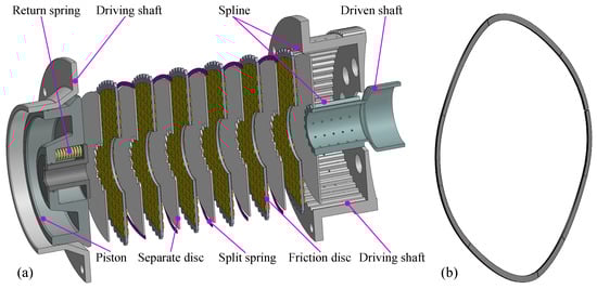
Figure 1.
(a) The 3D structure schematic diagram of wet multi-disc clutches for helicopters. (b) The split spring [7].
The bulking deformation of the friction elements in wet multi-disc clutches is widely recognized as a critical phenomenon that significantly affects transmission efficiency, thermal safety and overall performance of the driveline system. Recently, several researchers have conducted systematic studies on the mechanisms and influencing factors of buckling deformation, with a primary focus on automotive clutches. Initial research efforts were predominantly directed toward identifying the fundamental thermo-mechanical drivers that trigger thermal buckling. Li et al. [8] presented a buckling deformation model of friction elements to explore the effects of temperature distribution characteristics on thermal stresses associated with buckling. The results indicate that the radial temperature gradient is more conducive to inducing buckling deformation of the friction components. This finding was subsequently corroborated by Koranteng et al. [9] in their exploration of thermoelastic instability and thermal buckling of friction discs in dry clutches. The results further demonstrate that the radial temperature gradient plays a key role in the thermal buckling of friction discs. Gong et al. [10] explored the effects of temperature distribution characteristics and boundary conditions on the thermal buckling behaviors of automotive clutches. Yu et al. [11] and Wang et al. [12] consistently identified conical deformation as the most prevalent failure mode of friction pairs and separate discs, respectively, arising from thermal buckling. Additionally, Chen et al. [13] employed the finite element method to investigate the coupling relationship between thermoelastic instability and thermal buckling of friction elements. While existing literature has extensively characterized the mechanisms of buckling deformation, the transient thermal evolution resulting from successive shifting operation have been rarely reported.
Subsequent studies have expanded to explore the thermal-mechanical coupling mechanisms and the parametric analysis of buckling phenomena to various operation conditions. Xiong et al. [14] constructed a transient temperature model to assess the impact of temperature variation on cone shape buckling. The corresponding results show that under low lubrication conditions with an operating speed of 700 rpm, a maximum radial temperature discrepancy of 99.5 °C induces a radial stress of 12.7 MPa, which directly triggers conical bulking. Wu et al. [15] developed thermal-mechanical and thermal safety threshold models to examine the temperature-induced failure of wet friction components, revealing that the radial failure temperature reaches 86.9 °C at an operating 1300 rpm and 93.6 °C at a working pressure of 1 MPa. Cui et al. [16,17] and Xue et al. [18,19] investigated the effects of the deformed discs on the dynamic response and tribodynamic behavior in the hydro-viscous drive and wet multi-disc clutches, respectively. The corresponding results reveal that the deformation of wet friction discs significantly contributes to an increase in viscous torque. Recent research efforts have shifted toward understanding the effects of buckling deformation on clutch performance. Yu et al. [20] confirmed through numerical simulations and test bench experiments that the deformed separate discs not only enlarge the circumferential and radial temperature differences but also significantly increase the friction torque. Cui et al. [21] developed a finite element model of conical friction pairs to investigate the thermal behavior of friction elements, and further noted that the conical friction pairs are prone to generating localized high-temperature and high-pressure spots in the clutch engagement phase, which exacerbates wear and reduces service life. To tackle the problem of incomplete disengagement and minimize torque losses in wet multi-disc clutches, Zhao et al. [22] designed small-angle conical separate plates to accelerate the separation process and explored the effect of conical separate discs on the clutch dynamic response using numerical methods and experimental bench tests. Similarly, Wu et al. [23] proposed a hybrid model integrating conventional mechanism methods with data-driven techniques to analyze the effects of cone-shaped friction discs on the torque characteristics of high-power clutches. Zhao et al. [24] further developed a mathematical model to investigate the time-varying thermodynamic characteristics of clutches with the post-buckling plates, and the proposed model was validated through a finite element method and a test bench experiment. Despite these valuable contributions of the aforementioned studies, limited information regarding the subsequent effects after wet friction elements experience buckling is applicable to engineering practice, and the current theoretical frameworks and technical approaches lack the capability to monitor or predict the initiation of buckling-induced failures in real-time. Furthermore, there is a notable paucity of research concerning aviation wet clutches, especially regarding the thermal behaviors of those equipped with conical separate discs for heavy-duty helicopters operating under successive shifting conditions, remains relatively scarce.
A review of the literature reveals that existing studies primarily concentrates on the buckling mechanism of friction elements in automotive wet clutches and the effect of buckling on clutch dynamics, typically utilizing a commercial finite element software such as ABAQUS 6.14 and ANSYS 18.0. However, little information is available for the dynamic and transient thermal characteristics of wet clutches with conical separate discs during successive shifting, especially in high-speed and heavy-duty helicopters. Consequently, this work endeavors to investigate the transient thermal characteristics of aviation wet clutches with conical separate discs in the successive shifting phase. Firstly, a compression elastic force model for conical separate discs and an equivalent gap model are introduced. Subsequently, a comprehensive thermal-fluid-dynamic model is proposed, which couples a dynamic model with a transient thermal model that considers the time-varying thermal parameters. Synchronously, the proposed comprehensive mathematical model is calculated, and the transient thermal behaviors of friction elements are explored. An equivalent gap model and a thermal-fluid-dynamic model are established in Section 2. Section 3 focuses on analyzing the dynamic behaviors of wet clutches and thermal characteristics of friction elements. A detailed discussion on the effects of operating parameters on transient thermal characteristics is provided in Section 4. In the end, Section 5 synthesizes the simulation results and formulates corresponding conclusions.
2. Mathematical Models of Dynamic and Heat Transfer
2.1. Conical Separate Disc Model
As shown in Figure 1, the separate discs are connected to the driven shaft via inner splines, while the friction discs are connected to the driving shaft via outer splines. The power transmission and interruption are accomplished by controlling the engagement and disengagement of friction elements. However, under high-temperature and high-pressure conditions, the conical buckling is the primary deformation mode of friction components [25]. Therefore, a simplified physical model of a conical separate disc is presented in Figure 2.
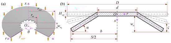
Figure 2.
(a) The simplified physical model of a conical separate disc. (b) The cross-section schematic of a conical separate disc.
2.1.1. Geometric Description of Conical Separate Disc
As illustrated in Figure 2, the height of the conical separate disc can be considered to increase linearly along the radial direction [24]. Hence, the geometric relationship between the cone angle and the outer radius of conical elements is presented in Equation (1):
where represents the cone angle; b is the outer radius of conical elements; D and d are the outer and inner diameters of undeformed separate discs, respectively.
The deformation height () and compression height () of conical separate discs are expressed in Equation (2):
where is the initial deflection.
2.1.2. Elastic Force Model of Conical Separate Disc
The elastic force () originated from the compression of conical separate discs is one of the driving forces causing asperity contact and sliding friction in various friction pairs. The elastic force is a function of the compression deformation and is described in Equation (3) [26]. A detailed derivation of this relationship is presented in Appendix A.
where the elastic modulus and the Poisson’s ratio are expressed by E and , respectively; is the thickness of conical separate discs; , , and S represent calculation coefficients.
2.2. Axial Dynamic Model of Clutch System
By regulating the control oil pressure within the piston chamber, the axial movement of the friction element and piston is controlled to achieve the power transmission and interruption. Considering the uniform conical buckling of friction elements, a coupled dynamic model of the operating process for a wet multi-discs clutch incorporating conical separate discs is established in Figure 3.
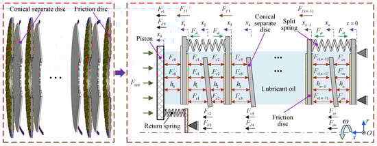
Figure 3.
The axial dynamics model of the wet multi-disc clutch with conical separate discs.
Following Newton’s law and force analysis in Figure 3, the axial dynamic equation describing the moving elements of the wet multi-disc clutch is derived and presented in Equation (4):
where m represents the mass; and represent the bearing capacity of the asperity and oil film, respectively; and are the spline friction forces; is damping force; the subscripts f, i, p and s denote the friction disc, the element label, the piston and the separate disc, respectively; is engagement force exerted by the control oil pressure; and are the stiffness of the return and split springs, respectively; and are the spring forces. , and are determined through calculations with Equation (5) [27].
where , s, and are the wave number, thickness, width, and center diameter of the wave spring, respectively; denotes the torque transmitted by a friction pair.
2.3. Gap Model of Friction Pair
As shown in Figure 2 and Figure 3, the outer diameter () and inner diameter () of the i-th friction pair with the conical separate disc can be calculated using Equation (6):
where i is an odd number, the ± symbol in Equation (6) adopts the negative value; otherwise, the positive value is used.
In Figure 2 and Figure 3, based on the principle that the volume of lubricant oil between friction pairs remains constant, the equivalent gap () of the i-th friction pairs under the contact state is expressed as follows:
As presented in Figure 2 and Figure 3, when the conical separate disc separates from the adjacent straight friction discs, the gap at the inner diameter () and the gap at the outer diameter () of the i-th friction pair can be expressed in Equation (8):
By combining Equations (7) and (8), the equivalent gap () of the i-th friction pair with the conical separate disc under separation conditions can be calculated in Equation (9):
When the conical separate disc separates from the adjacent friction disc or is in a state of critical contact, the following Equation (10) can be satisfied:
When the conical separate disc contacts the adjacent friction plate, Equation (11), presented below, can be satisfied:
2.4. Lubrication and Asperity Model
2.4.1. Lubrication Model
Assuming the gap between the friction pairs with conical separate discs is filled with lubricant oil to form full-film laminar lubrication, a fluid dynamic lubrication model for warped friction pairs is established in Equation (12) using the equivalent gap calculated in Section 2.3 [16,28,29]:
where , , , , and represent the friction lining thickness, the equivalent oil film thickness, the viscosity of lubricant oil, the flow factor, the friction material permeability and the error function, respectively.
Based on the structural features of the wet multi-disc clutch, the boundary condition corresponding to Equation (12) is expressed as . The dynamic bearing capacity of the oil film between warped friction pairs is derived and provided in Equation (13) [30]:
where and describe the inner radius and the outer radius, respectively; represents the asperity contact area coefficient.
2.4.2. Asperity Model
The contact model is established based on the following underlying assumptions: Firstly, the surface roughness of the friction elements follows a zero-mean Gaussian distribution, where the peak values exhibit mutual independence. Secondly, under the action of pressurized hydraulic oil, the asperities on the friction interface undergo negligible plastic deformation. On this basis, the asperity contact area () and the associated contact pressure () are described as functions of the film thickness ratio () [31]:
where R and are the radius and density of asperities, respectively; and are the deformation coefficient and roughness, respectively.
The contact ratio (B) of asperities in friction elements, regarded as a critical indicator, is proposed to characterize the contact states of friction interfaces, and the specific mathematical expression is presented in Equation (15):
The bearing capacity () of asperities in a warped friction pair is expressed as
2.5. Torque Model
In clutch engagement phase, the torque transmission mechanism undergoes a gradual transition from viscous torque to friction torque as the volume of hydraulic oil entering the piston chamber increases. In contrast, the torque transmission mechanism follows the inverse process during the disengagement phase. The respective expressions for the viscous torque () and friction torque () are given in Equation (17):
where and are the flow factor; denotes the friction coefficient, which can be determined using Equation (18) [32]:
where and represent the lubricant oil temperature and engagement pressure exerted on the friction pair, respectively.
The torque transmitted by the wet clutch comprises a friction torque and a viscous torque. Accounting for the torque composition and Newton’s law, the dynamic equation describing the torque characteristics of the wet multi-disc clutch system is formulated in Equation (19):
where the inertia and load torque of the are expressed by and , respectively.
2.6. Transient Thermal Model and Solution Method
2.6.1. Transient Thermal Model
As the properties of material and lubricant oil are assumed to remain constant with temperature, following heat transfer theory, the heat governing equation for the friction element can be expressed as [33]
where T denotes temperature; the specific heat capacity, density, and thermal conductivity are expressed by c, , and , respectively.
The temperature field of friction components exhibits an axisymmetric distribution, which is a result of their axisymmetric structures and thermal boundary conditions [34]. Consequently, a 2D transient thermal model tailored for friction elements is proposed herein to explore the transient thermal characteristics along the axial and radial directions. With a friction disc selected as a representative example, the meshing configurations of the friction disc and corresponding boundary conditions across different regions are illustrated in Figure 4.
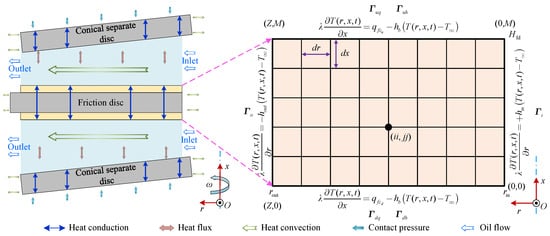
Figure 4.
The 2D physical model of heat transfer for the friction disc.
In clutch engagement phase, the collective effects of the friction torque and the considerable relative speed between the driving and driven discs generate heat flux, most of which is transferred to the friction elements. Consequently, the heat flux density transmitted to the friction elements can be calculated in Equation (21) [35]:
where the input heat flow density of the i-th separate disc and the i-th friction disc are expressed by and , respectively.
The heat convective coefficients corresponding to the inner radius and outer radius can be mathematically described in Equation (22):
The convective heat transfer occurs between the frictional contact interfaces and the lubricant oil film. Accordingly, the heat convective coefficient of the lubricant oil film within the local contact zones can be expressed in mathematical form as follows.
Besides, the heat convective coefficient corresponding to the lubricant oil within the groove can be mathematically described as follows:
The heat convective coefficient within the friction pair encompasses that corresponding to the lubricant oil film within local contact regions and the lubricant oil in the grooves, which can be mathematically expressed as follows:
The thermal radiation plays an insignificant role in shaping the temperature characteristics of wet friction elements. Therefore, only the effects of heat conduction and heat convection are considered in the present work. Furthermore, considering the symmetrical structure features and boundary conditions of the wet friction element, the numerical simulation can be performed on only half of the friction disc, significantly accelerating the simulation task. The lubricant oil is assumed to achieve full circulation. The initial temperatures of the clutch components and the lubricant oil set to [7]. Accordingly, as illustrated in Figure 4, the following boundary conditions and initial conditions for the proposed transient thermal model are mathematically described in Equation (26) [36]:
2.6.2. Solution Method for Transient Thermal Model
As illustrated in Figure 4, the solution zone (r, x, t) of the transient temperature field for the wet friction element is meshed using step sizes of , , and . Subsequently, the differential form of governing Equation (20) is derived and provided in Equation (27):
The explicit differential form for the transient heat transfer equation is derived as
The stability condition is presented in Equation (29):
3. Numerical Simulation
3.1. Model Parameters and Simulation Method
A numerical simulation model is constructed in MATLAB/Simulink 2022b to simulate the developed dynamic model and thermal-fluid-dynamic coupled model for aviation clutches with conical separate discs. The calculation flow chart of the proposed model is illustrated in Figure 5. Firstly, either the initial state or the results obtained from the preceding time step are first employed to calculate key geometric parameters of the friction pair, including outer diameter, inner diameter, and equivalent gap, among others. Secondly, the bearing capacity of asperities and oil film, alongside the elastic force, is determined. Thereafter, the force balance equations governing the axial force and torque of the elements are calculated to determine the corresponding displacements, velocities, accelerations, and output speeds. In terms of solving the proposed transient thermal model, the initial temperature field of the wet friction elements is first constructed. Subsequently, the dynamic results obtained from the kinetic model are employed to calculate the heat convective coefficients and the heat flux density. Then, the heat transfer equations and the boundary conditions are implemented to obtain the transient temperatures at each mesh node. Lastly, the above-mentioned simulation steps are iteratively circulated until the predefined simulation termination criteria are fulfilled. The ode23s solver is employed to calculate the proposed models. The maximum time step is set as s. Moreover, the maximum rotation speed, maximum transmitted power, and maximum engagement duration of the studied aviation clutch in the helicopter transmission system is 2200 rpm, 160 kW, and 2 s, respectively. The simulation parameters essential for solving the proposed dynamic model and transient thermal model are recorded in Table 1.
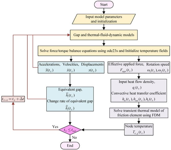
Figure 5.
The calculation flow chart of the proposed model.

Table 1.
Simulation parameters of the proposed models.
3.2. Dynamic and Thermodynamic Response
As presented in Figure 6a, the control oil pressure is 0 before 0.1 s, followed by a linear increase that brings it to 1.7 MPa at 0.25 s. Then the pressure remains constant for a period, before undergoing a linear decrease to 0 between 1.3 s and 1.5 s. Beyond 1.5 s, the pressure remains a steady state of zero. For the aviation clutch system, the input rotation speed is configured to 2200 rpm, with the friction components and lubrication oil preconditioned to an initial temperature of 30 °C. In the numerical implementation of the proposed model, the fourth friction disc is specifically chosen for the subsequent analysis to investigate the temperature characteristics. A mesh independence study was conducted to optimize the numerical model configuration. Three mesh schemes with axial × radial node distributions of , and were evaluated. The transient peak temperature of the friction disc is determined as the key evaluation indicator. Comparative analysis demonstrated that beyond the mesh, the relative deviation of temperature predictions decreased to 1.83%, while the solution time cost increased by approximately 2.4 times. To balance numerical accuracy and computational efficiency, the mesh scheme was ultimately adopted for subsequent simulations. The corresponding simulation results for the aviation clutch in a single shifting process are detailed in Figure 6, Figure 7 and Figure 8.
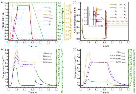
Figure 6.
The dynamic response curves during a single shifting operation, corresponding to (a) torque and rotation speed, (b) equivalent gap, (c) radial node temperature, and (d) axial node temperature.
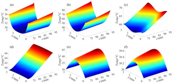
Figure 7.
The transient temperature field across the fourth friction disc for a single shifting operation at (a) 0.2 s, (b) 0.45 s, (c) 0.7 s, (d) 1 s, (e) 2 s, and (f) 3 s.
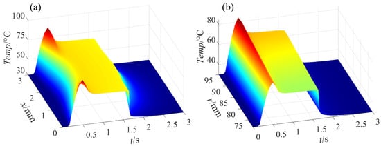
Figure 8.
The temperature dynamic response characteristics for a single shifting operation of (a) node (298, :) and (b) node (:, 60) for a rotation speed of 2200 rpm.
In the aviation clutch engagement, Figure 6a,b illustrate that increasing the control oil pressure induces a sharp decrease in the friction pair gap. Consequently, the viscous torque first increases before decaying to zero. In contrast, the friction torque rises and then stabilizes. The rotation speed of the driven shaft accelerates to 2200 rpm and then remains a constant at that value. Figure 6c,d indicate that the radial temperature gradient first increases, then decreases, increases again, and finally decreases, and the axial temperature gradient undergoes an increase followed by a decrease. Specifically, in the engagement phase, the heat flux density imparted to the wet friction elements presents a radially increasing trend. Since the heat flux density of the outer ring exceeds that of the inner ring, the outer ring attains a relatively higher temperature. Furthermore, the friction surface temperature is significantly higher than the interior of the friction disc. These results ultimately cause an increase in both radial and axial temperature gradients. A maximum temperature of 84.86 °C is recorded for the friction disc at 0.505 s. Meanwhile, the radial temperature gradient peaks at 39.29 °C at 0.427 s, and the axial temperature gradient reaches its maximum of 12.67 °C at 0.513 s. After engagement is complete, the thermal conduction primarily occurs within the friction disc, and the temperature field of the friction disc gradually transitions to a steady state, causing the radial temperature gradient to diminish progressively. However, in the disengagement of the wet clutch, a reduction in the control oil pressure induces the friction torque to gradually attenuate to zero, the gap between the friction pairs to expand, and the viscous torque to first increase transiently and then decay. Concurrently, the rotation speed of the output shaft gradually drops from 2200 rpm to a standstill, and the widened friction pair gap facilitates increased inflow of low-temperature lubrication oil into the friction pairs. Owing to the fact that the cooling rate at the inlet exceeds that at the outlet and an increase in the relative speed intensifies frictional heat generation, the radial temperature gradient across the friction surface sharply increases before gradually approaching zero.
Figure 7 depicts the transient temperature field across the fourth friction disc during a single shifting operation. In the clutch engagement phase (0.1 s∼0.577 s), the friction interface temperature rises sharply, reaching 84.86 °C at 0.505 s, which is attributed to increased frictional heat flux at the interface. The radial gradients indicate higher heat flux density at the outer ring. As the clutch transitions to disengagement (1.417 s∼3 s), the temperature decreases gradually, driven by the infiltration of lubricant oil into the widened friction pair gap. The lubricant oil infiltration effect results in a surface temperature of the friction components that is lower than the internal temperature of the friction components. Ultimately, the temperature of the friction disc reverts to the inlet temperature level of the lubricant oil. Besides, the temperature distribution of friction elements demonstrates approximate symmetry with respect to the central plane (). As illustrated in Figure 8, the temperature of the friction disc exhibits a parabolic variation trend in the axial direction, while its radial temperature follows a linear distribution pattern.
4. Results Analysis and Discussion
4.1. Effect of Shifting Interval
The numerical simulations are performed to assess the effect of shifting interval on transient thermal characteristics of the friction disc. As presented in Figure 9, the shifting interval is exclusively adjusted to 2 s, 2.2 s, and 2.3 s, while other operating conditions are held constant. Notably, the shifting cycle count, control oil pressure, rotation speed, and lubrication oil temperature are fixed at 3, 1.7 MPa, 2200 rpm, and 30 °C, respectively. The dynamic temperature responses obtained from the simulation are presented in Figure 10 and Table 2.
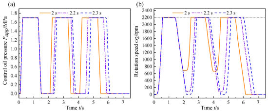
Figure 9.
The curves of (a) the control oil pressure and (b) the rotation speed response for different shifting intervals.
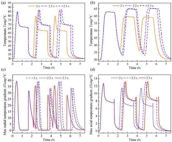
Figure 10.
The dynamic temperature response curves of (a) node (298, 60), (b) node (298, 30), (c) maximum radial temperature gradient, and (d) maximum axial temperature gradient with different shifting intervals.
Table 2.
Maximum radial and axial temperature gradients with different shifting intervals.
As illustrated in Figure 10, the temperature evolution of the friction element exhibits distinct periodic characteristics. The shifting interval of 2 s corresponds to a relatively earlier temperature peak of 79.942 °C (2.432 s), and the peak temperature gradually decreases as the shifting frequency increases. As depicted in Figure 9, shortening the shifting interval elevates the initial rotation speed of the output shaft upon the clutch re-engagement, thereby reducing the relative speed between the driving and driven shafts. The diminished relative speed directly contributes to a reduction in friction heat generation, consequently leading to a decrease in the temperature of the friction element with an increase in the shifting frequency. Notably, extending the shifting interval not only exacerbates the lag in the temperature response of friction discs but also causes a significant rise in peak temperatures, with the maximum value reaching 87.338 °C at 5.114 s. Moreover, an increase in shifting intervals and in successive shifting frequency collectively facilitates substantial heat accumulation, causing a persistent rise in the peak temperature of the friction discs. In the absence of effective and prompt cooling measures, this progressive thermal accumulation will eventually result in the failure of the friction plates due to high-temperature ablation. Furthermore, Figure 10c,d and Table 2 demonstrate that extending the shifting interval substantially increases the peak axial and radial temperature gradients of the friction element. Specifically, the maximum radial temperature gradient increased from 35.853 °C to 39.237 °C, corresponding to a relative increase of 9.44%. Meanwhile, the maximum axial temperature gradient increased from 11.482 °C to 13.196 °C, representing a more pronounced relative elevation of 14.93%. These results collectively indicate that when the friction components are not sufficiently cooled, extending the shifting interval leads to a larger relative speed upon clutch re-engagement. The increased relative speed exacerbates temperature gradients in the friction components.
4.2. Effect of Rotation Speed
To investigate the influence of input rotation speed on transient thermal responses, this key parameter is exclusively varied in the simulation, with values specified as 1600 rpm, 1900 rpm, and 2200 rpm. Meanwhile, all other operating conditions are maintained constant, including a control oil pressure of 1.7 MPa, a shifting cycle count of 3 and a shifting interval of 2.3 s. The corresponding dynamic temperature response behaviors of the friction disc are depicted in Figure 11.
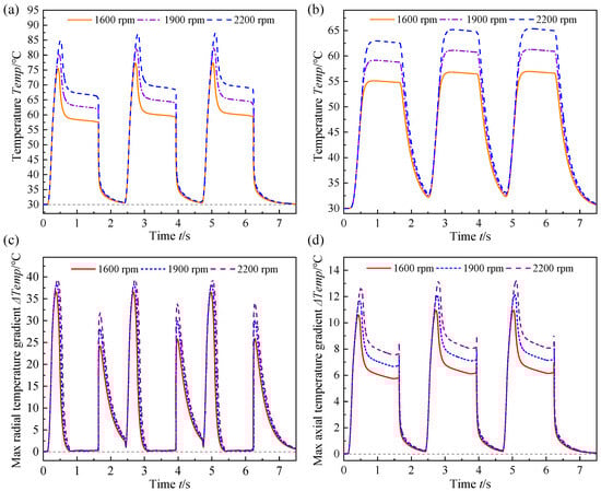
Figure 11.
The dynamic temperature response curves of (a) node (298, 60), (b) node (298, 30), (c) maximum radial temperature gradient, and (d) maximum axial temperature gradient with different rotation speeds.
As shown in Figure 11, the temperature evolution of the friction disc also exhibits a periodic characteristic. As the rotation speed increases from 1600 rpm to 2200 rpm, the peak temperatures at nodes (298, 60) and (298, 30) both rise significantly, accompanied by a delayed occurrence of the temperature peaks. The maximum temperature of the friction disc is 87.338 °C at 5.114 s. Concurrently, the cooling rate exhibits an increasing trend with the elevation of the rotation speed, indicating that the heat exchange efficiency between the friction components and lubricant oil is enhanced under high-speed conditions, thereby accelerating heat dissipation. Furthermore, the results presented in Figure 11c,d and Table 3 demonstrate that both the maximum radial and axial temperature gradients increase progressively with increasing the rotation speed [35]. Specifically, the maximum radial temperature gradient increased from 36.486 °C to 39.237 °C, representing a relative increase of 7.54%. The maximum axial temperature gradient rises from 10.952 °C to 13.196 °C, reflecting a more pronounced relative increase of 20.49%. In the engagement phase, an elevated rotation speed intensifies the friction-induced heating effect and extends the engagement duration. The extended engagement process facilitates the infiltration of cooling lubricant oil into the friction pair, but the substantial friction heat generated between the wet components cannot be rapidly dissipated, which ultimately results in a significant rise in both peak temperatures and temperature gradients. Conversely, during the disengagement phase, higher rotation speeds augment convective heat transfer efficiency between the friction components and the lubricant oil, thereby accelerating the dissipation of friction heat [32]. This is specifically manifested by an increased cooling rate, which ultimately contributes to a rapid decrease in the surface temperature of the friction discs.
Table 3.
Maximum radial and axial temperature gradients with different rotation speeds.
4.3. Effect of Control Oil Pressure
The simulation are conducted to examine the effect of control oil pressure on transient thermal characteristics. The control oil pressure is solely adjusted to 1.5 MPa, 1.7 MPa, and 1.9 MPa while other operating conditions are fixed. Specifically, the shifting interval is maintained at 2.3 s, the rotation speed is 2200 rpm, and the shifting cycle count is prescribed at 3. The resulting dynamic temperature response is presented in Figure 12.
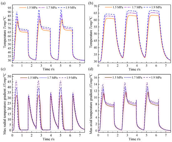
Figure 12.
The dynamic temperature response curves of (a) node (298, 60), (b) node (298, 30), (c) maximum radial temperature gradient, and (d) maximum axial temperature gradient with different control oil pressure.
In Figure 12, the temperature evolution of the friction disc also demonstrates a periodic behavior. Substantial increments are observed in the maximum temperature, the temperature gradient, and the temperature rise rate of the friction disc [37]. The maximum temperature is 93.146 °C at 5.072 s. Equations (4) and (21) indicate that an elevation in control oil pressure induces a rise in the exerted pressure at the friction interface, thereby substantially enhancing the contribution of asperity friction torque to the temperature field. This dual-effect phenomenon accelerates the engagement and lubricant oil extrusion processes while simultaneously augmenting the heat flux input to the friction interface. Furthermore, as revealed by the results from Figure 12c,d and Table 4, when the control oil pressure increases from 1.5 MPa to 1.9 MPa, the maximum radial temperature gradient rises from 32.237 °C to 45.987 °C, representing a relative increase of 42.65%. This phenomenon can be attributed to the more pronounced localized accumulation of frictional heat under high pressure, which amplifies the non-uniformity of radial heat conduction [34]. Additionally, with the elevation of the control oil pressure, the engagement time narrows, and the sliding friction work increases. Consequently, the heat flux density at the friction interface rises, and the lubricant oil flow decreases, while the internal heat transfer capacity of the components remains constant. Ultimately, the maximum axial temperature gradient increases from 11.719 °C to 14.572 °C, representing a 24.35% rise. The aforementioned results indicate that the radial thermal imbalance proves more severe than the axial imbalance, rendering it more susceptible to inducing thermal stress-related issues [38].
Table 4.
Maximum radial and axial temperature gradients with different control oil pressure.
4.4. Discussion
This study presents a numerically investigation into the transient thermal characteristics of aviation clutches with conical separate discs under successive shifting maneuvers. By evaluating the effects of shifting interval, input rotation speed, and control oil pressure, this research provides pivotal technical and theoretical insights for the thermal design and performance optimization of automatic transmission systems, especially for high-speed and heavy-duty machinery.
The aforementioned results reveal that control oil pressure serves as the dominant factor governing temperature radial gradient, followed sequentially by shifting interval, and rotation speed. In contrast, the hierarchy of influencing factors for axial temperature gradient is determined as control oil pressure, rotation speed and shifting interval. Practically, optimizing operating parameters through shortening shifting intervals, rationalizing rotation speed, and calibrating the minimum required control oil pressure yields dual benefits: this strategy not only effectively alleviates thermal stress but also contributes to extending the service life of key components. The main limitations of this study are that the proposed model excludes temperature-dependent parameters, groove geometry, and detailed flow field behaviors within the friction interfaces. In the future, data-driven macro-micro thermodynamic models incorporating temperature-dependent parameters should be developed to numerically and experimentally investigate the effects of long-term cyclic gear shifting and explore the shifting strategies, condition monitoring, and fault diagnosis of aviation clutches.
5. Conclusions
This study develops a comprehensive numerical model that integrates a dynamic model considering the conical separate discs and a thermal model with time-varying parameters. Subsequently, the effects of shifting interval, rotation speed, and control oil pressure on the transient thermal characteristics of aviation clutches are systematically explored. The key conclusions derived therefrom are briefly summarized as follows:
- (1)
- In a single shifting operation of the aviation wet clutch, the temperature field of the friction elements successively rises and then decreases. Additionally, the radial temperature gradient initially increases, then decreases, increases again, and finally decreases, while the axial temperature gradient experiences an initial increase followed by a decrease.
- (2)
- In the successive shifting, extending the shift interval from 2 s to 2.3 s yielded a maximum temperature of 87.338 °C. Increasing the input shaft speed from 1600 rpm to 2200 rpm also elevates the maximum temperature to 87.338 °C. Raising the control oil pressure from 1.5 MPa to 1.9 MPa further increases the maximum temperature to 93.146 °C. Corresponding results indicate that the control oil pressure exerts the most prominent influence on the maximum temperature among the three parameters.
- (3)
- Throughout the successive shifting of the aviation clutch, the control oil pressure exerts the most significant influence on the maximum radial temperature gradient, which surges by 42.65%. The value substantially exceeds the increments induced by the extended shifting interval (9.44%) and elevated rotation speed (7.54%). For the maximum axial temperature gradient, the control oil pressure results in a relative increase of 24.35%, followed by the rotation speed (20.49%) and the shifting interval (14.93%).
- (4)
- To mitigate overheating and enhance the temperature uniformity of wet clutches with conical discs during helicopter successive shifting operation, the operation parameters are optimized by rationally adjusting the relative rotational speeds, appropriately shortening the shift intervals, and calibrating the minimum required control oil pressure. Critical to these modifications is that they must align with the specified operational performance requirements of the aviation clutch to preserve functional integrity.
Author Contributions
Conceptualization, X.L. and H.Y.; methodology, X.L.; software, X.L.; validation, X.L. and D.W.; formal analysis, X.L. and D.W.; investigation, Y.X.; resources, H.Y.; data curation, Y.Y. and M.Y.; writing—original draft preparation, X.L.; writing—review and editing, X.L. and D.W.; visualization, Y.Y.; supervision, H.Y.; project administration, Y.X.; funding acquisition, Y.Y. All authors have read and agreed to the published version of the manuscript.
Funding
This research was funded by the National Natural Science Foundation of China Youth Program, grant number 52405609, and the Natural Science Foundation of Hunan Province Youth Program, grant number 2023JJ40049.
Institutional Review Board Statement
Not applicable.
Informed Consent Statement
Not applicable.
Data Availability Statement
The raw data supporting the conclusions of this article will be made available by the authors on request.
Acknowledgments
The authors acknowledge facility resources and support provided by the State Key Laboratory of Precision Manufacturing for Extreme Service Performance, Central South University.
Conflicts of Interest
Authors Mei Yin and Yexin Xiao were employed by the company AECC Hunan Aviation Powerplant Research Institute. The remaining authors declare that the research was conducted in the absence of any commercial or financial relationships that could be construed as a potential conflict of interest.
Nomenclature
| asperity contact area coefficient | specific heat of friction disc (J/kg°C) | ||
| specific heat of the lubricant oil (J/kg°C) | specific heat of separate disc (J/kg°C) | ||
| damping coefficient (N·s/m) | friction lining thickness (m) | ||
| equivalent Young’s modulus (Pa) | bearing capacity of asperity and oil film (N) | ||
| elastic force of conical separate disc (N) | , | spline friction force (N) | |
| damping force (N) | , | spring force (N) | |
| exerted force of piston (N) | friction coefficient | ||
| initial and equivalent gap of friction pairs (m) | , | convective coefficients at inner and outer (W/m2°C) | |
| , | convective coefficients at friction pairs (W/m2°C) | friction and separate disc thickness (m) | |
| driven shaft inertia (kg·m2) | , | spring stiffness (N/m) | |
| piston, separate and friction disc mass (kg) | n | friction pairs number | |
| heat flow density of friction disc (W/m2) | heat flow density of separate disc (W/m2) | ||
| inner and outer radius of conical friction pair (m) | pitch circle radius of spline (m) | ||
| inner and outer radius of friction element (m) | , | friction and viscous torque (N·m) | |
| load torque (N·m) | x | clutch element position (m) | |
| clutch element velocity (m/s) | clutch element acceleration (m/s2) | ||
| rotation speed (r/min) | relative speed (r/min) | ||
| deformation height (m) | cone angle (°) | ||
| asperity density (m−2) | friction material permeability (m2) | ||
| thermal conductivity of friction disc (W/m°C) | thermal conductivity of lubricant oil (W/m°C) | ||
| thermal conductivity of separate disc (W/m°C) | friction disc density (kg/m3) | ||
| lubricant oil density (kg/m3) | separate disc density (kg/m3) | ||
| compression height of conical separate disc (m) | dynamic viscosity (Pa·s) | ||
| roughness (m) | flow factors |
Appendix A
As depicted in Figure A1, the differential element is taken from the geometric mid-plane of wet friction components.

Figure A1.
The schematic of (a) Mid-plane of the wet friction components, and (b) internal force vectors of the differential element.
Regarding the load and bending forces, their corresponding balance equations in Figure 2 and Figure A1 may be formulated as follows:
where F is load force, and M is bending force; the subscript r, and x represent corresponding components along radial, circumferential, axial direction, respectively.
Following by the hook’s theory, the strain responses associated with the friction element may be formulated in Equation (A2).
The internal forces can be derived and given in Equation (A3).
where and are the normal internal forces; denotes the internal force function at mid-plane of the friction element; u represents the displacement.
The bending force equation in radial and axial direction can be derived and presented in Equation (A4).
where and describe the circumferential and radial displacements, respectively; and can be obtained in Equation (A5).
Integrating Equations (A4) and (A5) yields the displacement equation as follows.
where , and represent the Laplace Operator, differential operator and lateral load, respectively.
Under the conditions of uniform axial loading and circumferential symmetry, the corresponding plate deflection inherently maintains symmetry. Thus, Equation (A6) can be further simplified as:
where and represent the deflection and initial deflection under load, respectively; corresponding the maximum deflection and maximum initial deflection are expressed by and , respectively. is described in Equation (A8).
The mathematical relationship between deflection and maximum deflection can be established in Equation (A9).
where .
Furthermore, the mid-plane displacement and Galerkin equations are derived and provided in Equation (A10) under the governing geometric boundary conditions.
References
- Tan, W.Z.; Chen, Z.; Li, Z.Z.; Yan, H.Z. Thermal-Fluid-Solid Coupling Simulation and Oil Groove Structure Optimization of Wet Friction Clutch for High-Speed Helicopter. Machines 2023, 11, 296. [Google Scholar] [CrossRef]
- Zhang, Y.N.; Wang, D.Q.; Du, Y.F.; Wen, C.K.; Wang, L.Z.; Wu, Z.K. Sensorless wet clutch pressure control method for high-power tractors using physical and digital twins. Biosyst. Eng. 2026, 261, 104322. [Google Scholar] [CrossRef]
- Bao, H.Y.; Kong, W.D.; Hou, X.N.; Zhu, R.P. Analysis on temperature field of friction pair of aviation friction clutch based on different groove shapes of friction disk. J. Mech. Sci. Technol. 2021, 35, 3735–3742. [Google Scholar] [CrossRef]
- Bian, J.N.; Wu, H.M.; Yang, X.Y.; Ye, G.; Zhu, X.; Dai, Y. Thermal Characteristics Analysis of an Aerospace Friction Clutch Based on Thermal-Fluid-Solid Coupling. Lubricants 2025, 13, 469. [Google Scholar] [CrossRef]
- Wu, Y.; Liu, Y.; Chen, H.; Chen, Y.; Xie, D. An investigation into the failure mechanism of severe abrasion of high-speed train brake discs on snowy days. Eng. Fail. Anal. 2019, 101, 121–134. [Google Scholar] [CrossRef]
- Schneider, T.; Voelkel, K.; Pflaum, H.; Stahl, K. Investigating Failure Modes and Performance Impacts of Wet Clutches in Automotive Limited Slip Differentials. Lubricants 2024, 12, 70. [Google Scholar] [CrossRef]
- Li, X.K.; Wei, D.H.; Wang, H.; Yan, Y.X.; Yan, H.Z.; Yin, M.; Xiao, Y.X. Investigation on the Effects of Operating Parameters on the Transient Thermal Behavior of the Wet Clutch in Helicopters. Appl. Sci. 2025, 15, 10412. [Google Scholar] [CrossRef]
- Li, M.Y.; Ma, B.; Li, H.Y.; Li, H.Z.; Yu, L. Analysis of the thermal buckling of annular disks in clutches under the condition of radial temperature gradient. J. Therm. Stresses 2017, 40, 1275–1284. [Google Scholar] [CrossRef]
- Koranteng, K.; Shaahu, J.-S.; Ma, C.N.; Li, H.Y.; Yi, Y.B. The performance of Cu-based friction material in dry clutch engagement. Proc. Inst. Mech. Eng. Part J J. Eng. Tribol. 2021, 235, 1114–1123. [Google Scholar] [CrossRef]
- Gong, Y.B.; Ge, W.C.; Yi, Y.B. Finite element analysis of thermal buckling characteristics of automotive 430 dry clutch pressure plate. Int. J. Vehicle. Des. 2018, 78, 108–130. [Google Scholar] [CrossRef]
- Yu, L.; Ma, B.; Chen, M.; Li, H.Y.; Liu, J.K.; Li, M.Y. Investigation on the failure mechanism and safety mechanical-thermal boundary of a multi-disc clutch. Eng. Fail. Anal. 2019, 103, 319–334. [Google Scholar] [CrossRef]
- Wang, Q.L.; Wang, J.M.; Cui, H.W.; Wang, J.; Zhang, F. Numerical investigation into thermal buckling of friction pairs in hydro-viscous drive under nonlinear radial temperature distribution. Proc. Inst. Mech. Eng. Part J J. Eng. Tribol. 2022, 236, 1081–1090. [Google Scholar] [CrossRef]
- Chen, Z.; Yi, Y.B.; Bao, K. Prediction of thermally induced postbuckling of clutch disks using the finite element method. Proc. Inst. Mech. Eng. Part J J. Eng. Tribol. 2021, 235, 303–314. [Google Scholar] [CrossRef]
- Xiong, C.B.; Ma, B.O.; Li, H.Y.; Zhang, F.L.; Wu, D. Experimental Study and Thermal Analysis on the Buckling of Friction Components in Multi-Disc Clutch. J. Therm. Stresses 2015, 38, 1325–1345. [Google Scholar] [CrossRef]
- Wu, J.P.; Ding, A.; Yang, C.B.; Zhang, H.S.; Wang, L.Y.; Li, H.Y. Data-driven thermal safety threshold analysis of friction component based on macro-micro interaction model. Case. Stud. Therm. Eng. 2025, 74, 106821. [Google Scholar] [CrossRef]
- Cui, J.Z.; Hou, P.L.; Zhang, B.G.; Zhao, X.Y. Investigation of flow between deformed disks in hydro-viscous drive. Tribol. Int. 2018, 121, 287–301. [Google Scholar] [CrossRef]
- Cui, J.Z.; Zhang, D.; Xu, Y.W.; Ma, S.X.; Chen, G.T. A Coupling Model for Tribodynamic Behavior of the Hydroviscous Flexible Drive With Consideration of Saucer-Warping Deformation. Tribol. Trans. 2023, 66, 73–91. [Google Scholar] [CrossRef]
- Xue, J.Q.; Ma, B.; Xiong, C.B.; Yu, L.; Feng, Y.Q. The effect of disc deformation on the dynamic response of multi-disc systems: A tilting-impact model originating from the wet clutch. Proc. Inst. Mech. Eng. Part D J. Automob. Eng. 2025, 239, 5735–5751. [Google Scholar] [CrossRef]
- Xue, J.Q.; Ma, B.; Chen, M.; Yu, L.; Zheng, L.J. On the Effects of Disc Deformation on the Tilting-Induced Vibration of a Spline-Guided Spinning Disc with an Axial-Fixed Boundary. Appl. Sci. 2022, 12, 3637. [Google Scholar] [CrossRef]
- Yu, L.; Ma, B.; Chen, M.; Li, H.Y.; Liu, J.K. Investigation on the thermodynamic characteristics of the deformed separate plate in a multi-disc clutch. Eng. Fail. Anal. 2020, 110, 104385. [Google Scholar] [CrossRef]
- Cui, H.W.; Suo, Y.R.; Mei, B.Z.; Li, D.H.; Jiang, Y.Y.; Sun, H.; Zhang, L.Q. Research on the nonuniform contact characteristics and thermal behavior of friction pairs involving the radial conical buckling deformation in hydro-viscous drive. Numer. Heat Transf. Part A Appl. 2025, 86, 3211–3232. [Google Scholar] [CrossRef]
- Zhao, Q.; Ma, B.; Xiong, C.B.; Yu, L.; Fu, B.; Yan, S.F. Modeling of the Dynamics of Conical Separate Plates in a Wet Multi-Disc Clutch. Lubricants 2025, 13, 262. [Google Scholar] [CrossRef]
- Wu, J.P.; Cui, J.H.; Shu, W.Y.; Wang, L.Y.; Li, H.Y. Coupling mechanism and data-driven approaches for high power wet clutch torque modeling and analysis. Tribol. Int. 2024, 191, 109166. [Google Scholar] [CrossRef]
- Zhao, Q.; Ma, B.; Yu, L.; Dong, Y.; Yin, H.; Li, H.Y.; Liu, Y.J. Influence of buckled separate plate on the contact pressure and thermal properties in a multi-disc clutch. Proc. Inst. Mech. Eng. Part D J. Automob. Eng. 2025, 1–19. [Google Scholar] [CrossRef]
- Chen, Z.; Yi, Y.B.; Zhao, J.X. Fourier finite element model for prediction of thermal buckling in disc clutches and brakes. J. Therm. Stress. 2016, 39, 1241–1251. [Google Scholar] [CrossRef]
- Ozaki, S.; Tsuda, K.; Tominaga, J. Analyses of static and dynamic behavior of coned disk springs: Effects of friction boundaries. Thin-Walled Struct. 2012, 59, 132–143. [Google Scholar] [CrossRef]
- Li, X.K.; Yan, H.Z.; Wei, D.H.; Wu, J.M.; Yin, M.; Xiao, Y.X.; Li, K.F. Study on the Effect of Operating Conditions on the Friction Pair Gap in a Wet Multi-Disc Clutch in a Helicopter Transmission System. Appl. Sci. 2024, 14, 7751. [Google Scholar] [CrossRef]
- Cui, J.Z.; Xie, F.W.; Li, H.; Zhao, X.Y. Influences of deformed film gaps on dynamic torque behavior of hydroviscous drive. Tribol. Trans. 2021, 64, 477–500. [Google Scholar] [CrossRef]
- Patir, N.; Cheng, H.S. Application of Average Flow Model to Lubrication Between Rough Sliding Surfaces. J. Lubr. Technol. 1979, 101, 220–229. [Google Scholar] [CrossRef]
- Wu, B.Z.; Qin, D.T.; Hu, J.J.; Wang, X.; Wang, Y.; Lv, H. Analysis of influencing factors and changing laws on friction behavior of wet clutch. Tribol. Int. 2021, 162, 107125. [Google Scholar] [CrossRef]
- Yang, X.G.; Bao, H.Y.; Zhang, C.; Tan, W.Z.; Zhu, R.P. Influence of Groove Type on Friction Coefficient of Wet Friction Clutch Pair. Int. J. Automot. Technol. 2024, 25, 13–21. [Google Scholar] [CrossRef]
- Wu, J.P.; Zhao, P.; Yang, J.; Shu, W.Y.; Wang, L.Y. Digital twin transient temperature field of wet friction components based on the hybrid model optimizing dynamic parameters. Therm. Sci. Eng. Prog. 2025, 64, 103803. [Google Scholar] [CrossRef]
- Kakac, S.; Yener, Y.; Naveira-Cotta, C.P. Heat Conduction; CRC Press: Boca Raton, FL, USA, 2018. [Google Scholar] [CrossRef]
- Wu, J.P.; Zhao, P.; Shu, W.Y.; Yang, J.; Wang, L.Y.; Li, P.P. Self-adaptive physics-informed neural networks for solving the heat transfer problem in wet friction components of transmission system. Int. J. Therm. Sci. 2025, 220, 110390. [Google Scholar] [CrossRef]
- Wang, Q.L.; Zhang, X.B.; Wang, D.G.; Cui, H.W.; Zhang, S.; Wang, J.M. Numerical simulation and experimental investigation on the thermal-fluid-solid multi-physical field coupling characteristics of wet friction pairs considering cavitation effect. Appl. Therm. Eng. 2025, 260, 124955. [Google Scholar] [CrossRef]
- Jin, Y.C.; Chen, L.; Cheng, C. Thermal behavior of friction discs in dry clutches based on a non-uniform pressure model. Case Stud. Therm. Eng. 2022, 32, 101895. [Google Scholar] [CrossRef]
- Wu, J.P.; Yang, C.B.; Zhang, H.S.; Wang, L.Y.; Li, H.Y. Numerical analysis of micro-textured friction element interface temperature fields under mixed lubrication. Int. Commun. Heat Mass 2025, 163, 108743. [Google Scholar] [CrossRef]
- Yu, L.; Ma, B.; Li, H.Y.; Liu, J.K.; Li, M.Y. Numerical and Experimental Studies of a Wet Multidisc Clutch on Temperature and Stress Fields Excited by the Concentrated Load. Tribol. Trans. 2019, 62, 8–21. [Google Scholar] [CrossRef]
Disclaimer/Publisher’s Note: The statements, opinions and data contained in all publications are solely those of the individual author(s) and contributor(s) and not of MDPI and/or the editor(s). MDPI and/or the editor(s) disclaim responsibility for any injury to people or property resulting from any ideas, methods, instructions or products referred to in the content. |
© 2025 by the authors. Licensee MDPI, Basel, Switzerland. This article is an open access article distributed under the terms and conditions of the Creative Commons Attribution (CC BY) license.