Abstract
This study proposed a surface modification method, based on petal-shaped micro-pit texture, allowing to solve the problem of significant wear of the stator caused by the oil film rupture in the metal-rubber friction pair of the screw pump under complex conditions in the later stages of oilfield extraction. A geometric model of the petal-shaped micro-pit texture on the stator rubber surface and a mathematical model of the hydrodynamic lubrication flow field based on the Reynolds equation were developed. Computational Fluid Dynamics (CFD) simulations and friction tests were conducted to systematically study the influence of the medium flow direction, texture area ratio, and texture size on the lubrication performance. The obtained results showed that compared with the flow in the x-direction, the load-carrying capacity of the oil film was increased by more than 0.93% when the medium flowed in y-direction, and it reached its optimal value at an area of 10%. When the area ratio reached 60%, the interference effect of the flow field reduced the pressure by 6.98%. The increase of the size of the petals allowed to expand the positive pressure zone and increase the net load-carrying capacity. Furthermore, friction tests demonstrated that the friction coefficient was decreased with the increase of the texture size and increased with the increase of the texture area ratio. The petal-shaped micro-pit texture with size of 350 μm and an area ratio of 10% demonstrated the lowest friction coefficient and highest wear resistance.
1. Introduction
As many oilfields in China enter the later stages of extraction, screw pump oil production systems are being more adopted to meet the unique demands of specialized reservoirs, such as high-viscosity heavy oil and high-sand oil [1,2,3,4,5]. The screw pump is a crucial element for power transfer. In complex operating conditions featuring low speed and high load, the oil film on the moving pair surface, which consists of a metal stator and rubber rotor, cannot reach stability. This results in significant degradation of the rubber stator, leading to the reduction of the mechanical efficiency and service life of the screw pump. Thus, wear becomes a crucial element affecting the operating efficiency of screw pump oil production systems. This is considered as a crucial aspect affecting the operating efficiency of screw pump oil production systems [6,7,8,9,10]. At present, the studies on technologies for reducing friction and drag at the interfacing surfaces of screw pump stators and rotors mainly focus on surface coatings for metallic rotors, chemical modifications to rubber stator surfaces, and formulations for stator rubber [11,12,13,14,15].
Texture treatment is a surface modification technique using ultra-precision machining to create micro-topographies with specific shape and size on material surfaces, allowing to enhance the tribological properties between mating pairs [16,17]. At present, researchers manipulate many parameters (e.g., the shape, angle, depth, width, and density of the texture) to allow the surface micro-texture to significantly reduce the friction and resistance under various operating conditions. This technology is widely used in many components, including pistons, cutting tools, sliding bearings, and others [18]. Bijani et al. [19] studied the impact of surface texture on the friction coefficient of lubricated parallel sliding surfaces. Their results showed that the surface texture facilitates the film formation, which increased the load-carrying capacity while reducing the friction coefficient. Xia et al. [20] investigated the impact of circular, heart-shaped, and composite circular-heart-shaped surface textures on the tribological characteristics of axial piston pump valve plate friction pairs. The results demonstrated that heart-shaped surface textures exhibited high anti-wear performance under various operating situations, which made them more appropriate for a wide range of applications. Wei et al. [21] conducted the anti-wear performance of fan-shaped surface textures through numerical simulations and experiments. Their results showed that the fan-shaped surface texture had higher anti-wear performance than conventional circular surface textures. Liu et al. [22] explored the impact of honeycomb hexagonal textures on the lubrication performance of rubber used in screw pump stators, based on bionic principles. Their results indicated that increasing the size of the hexagonal texture while decreasing groove width resulted in decreasing the area of the positive pressure region and an increasing that of the negative pressure region, leading to the reduction of the friction-reducing effect of the texture. Shi et al. [23] developed a rhombic texture inspired by rhombic rattlesnakes and studied its dynamic lubrication performance through numerical simulation. Their results showed that an area ratio of rhombic pit texture of 27%, along with a depth of 20 μm, a long side angle of 74°, and an angle of 0° results in the maximizing of net load-carrying capacity within the oil film, the dynamic lubrication performance, and the wear reduction, while minimizing the friction coefficient. Zhang et al. [24] studied the tribological performance of surfaces with different texture depths. Their manufactured these surfaces using laser surface texturing and ultra-precision diamond cutting techniques. Their results demonstrated that the surface roughness significantly reduced the friction and wear. Cheng et al. [25] investigated the impact of the texture density on the tribological properties of PEO/PTFE composite coatings. Their results indicated that when the area density of the texture increased, the storage capacity of the composite coating also increased. However, this increase came at the decreasing the load-carrying capacity. Li et al. [26] employed femtosecond laser processing to fabricate herringbone groove textures on cemented carbide at different densities. They then studied the impact of the texture area on tribological properties. Their results indicated that compared with non-textured samples, herringbone textures of a particular density decreased friction force on YT15 cemented carbide surfaces.
Many studies have been conducted on the tribological features of textured surfaces, namely their friction behavior. It is known that the anti-friction mechanism is mainly attributed to the hydrodynamic lubrication effect provided by the lubricating medium within micro-grooves. Muchammad et al. [27] investigated the impact of the texture depth on the dynamic lubrication performance of bearings through computational fluid dynamics simulations. Their results demonstrated that when surface texture depth increased, the dynamic lubrication performance also increased. However, when the depth of the texture increased and its length decreased, the cavitation area was reduced. Traore et al. [28] examined the impacts of the flow velocity and texture depth on the hydrodynamic properties of lubricating fluids, demonstrating that their increased significantly decreased the friction coefficient. The frictional interactions in metal-rubber contact pairs are more complex than those in metal-metal contact pairs. As a result, they have been rarely studied. The use of surface texture technology to improve the tribological characteristics of metal-rubber interfaces is crucial in engineering applications. In conclusion, many surface texture preparation techniques can significantly enhance the tribological characteristics of materials. In addition, most of the existing studies tackle hard materials, while soft materials have been rarely studied.
In addition, surface textures can be categorized into either convex textures and pit/groove textures [29,30,31]. However, the high manufacturing costs and inherent geometric difficulties associated with reproducing convex textures have led most current studies to concentrate on pit/groove textures [32,33,34,35]. As illustrated in Figure 1, under hydrodynamic lubrication conditions, lubricant flow within the pits generates localized hydrodynamic pressure, which in turn produces thrust between the two contact surfaces. This thrust, induced by the surface texture, enhances the load-bearing capacity of the lubricated surface and improves its overall tribological performance [32,36,37]. Additionally, pit textures serve as reservoirs for storing lubricants and as traps for abrasive particles and wear debris, thereby reducing wear on the contact surfaces [19,38,39]. The shape of micro-pit textures represents a critical geometric feature that influences their hydrodynamic behavior, directly impacting both hydrodynamic pressure generation and lubricant storage [40]. To determine the optimal texture shape under specific working conditions, numerous scholars have systematically compared the tribological performance of various texture shapes. Yu et al. [41] compared triangular, circular, and square textures on polymer-coated surfaces, demonstrating that triangular textures yielded the poorest tribological performance, whereas circular textures exhibited the lowest wear rate and wear volume. This superior performance of circular textures was attributed to their high geometric uniformity, which reduces deformation and stress concentration while facilitating stable lubricant film formation and effective debris retention. Tang et al. [42] investigated the effects of three bionic textures—triangular, hexagonal, and linear grooves—on the lubrication performance of water-lubricated bearings. Their research elucidated that the hexagonal textures provided the optimal lubrication performance in the divergent region. Furthermore, Zhang et al. [40] employed genetic algorithm optimization to demonstrate that bullet-shaped and fish-shaped textures exhibit superior frictional properties under unidirectional sliding conditions.

Figure 1.
Lubrication mechanism of surface texture storage lubricant and wear debris [19,39].
With a deeper understanding of the tribological mechanisms of surface textures and the rapid advancement of manufacturing technologies, researchers have increasingly explored texture designs beyond conventional simplistic geometries. Zhang et al. [43] developed a composite surface with gradient wettability, enhancing lubricant backflow and significantly improving the overall lubrication performance. Jing et al. [44] changed the surface morphology of the disc and slider (disordered nano-scale convex structure, dense brush structure, convex structure) by coating AF oleophobic layer, and measured the oil film thickness and lubricant distribution. To enhance the lubrication performance of parallel slider bearings, Uddin et al. [45] proposed a star-shaped surface texture leveraging the excellent anti-wear properties of triangular textures. Their research demonstrated that such textures can substantially increase bearing capacity, reduce friction force, and exhibit excellent hydrodynamic lubrication effects. Liu et al. [46] an irregular bullet-shaped texture, combining concentric circular patterns with multi-layer rectangular patterns. Their results indicated that the convergence effect of the bullet-shaped texture enhances hydrodynamic lubrication within the groove. Jing et al. [47] fabricated a crescent array texture with anisotropic wetting properties, investigating how texture parameters influence its anisotropic wettability. Gui et al. [48] conducted fluid-solid coupling analysis on double-layer composite bionic diatom textures in water-lubricated bearings. Their findings revealed that double-layer textures outperform single-layer textures in improving bearing capacity and reducing the friction coefficient of water-lubricated bearings.
Evidently, complex-shaped textures, with their enhanced design flexibility, offer novel opportunities for precise control of lubricant flow, optimization of wear debris storage capacity, and improvement of contact stress distribution. Considering the established advantages of circular textures—such as their excellent geometric uniformity, minimal stress concentration, and favorable oil film formation—this study proposes a petal-shaped structure composed of multiple arc segments. This design aims to enhance the performance of the mating pair by leveraging the unique radial geometric characteristics of the petal-shaped features. Consequently, this study examined the petal-shaped micro-pit texture of the stator rubber in a screw pump. It developed a geometric model for the micro-pit petal-shaped texture and a mathematical model for evaluating the dynamic lubrication performance inside the flow field on the textured surface. The influence of the area ratio and diameter of the petal-shaped micro-pit texture on its dynamic lubrication performance were studied, concurrently validating the tribological performance linked to this texture by experimentation. The obtained results provided a design framework for reducing the friction and drag on the textured surface of stator rubber in screw pumps, increasing the dynamic lubrication performance between the stator and rotor friction pairs, reducing friction, and increasing wear resistance in stator rubber components.
2. Analysis of the Petal-Shaped Micro-Pit Texture Model on the Rubber Surface of the Stator of Screw Pumps
2.1. Geometric Model of Petal-Shaped Micro-Pit Texture on the Inner Surface of the Stator Rubber of the Screw Pumps
Screw pumps consist of a metallic rotor and a rubber stator liner. In the oil extraction process, the rubber stator undergoes significant wear, which adversely affects the performance of the screw pump. This study systematically arranged the petal-shaped micro-pit texture on the surface of the rubber to modify the hydrodynamic lubrication effect between the rubber and the screw pump stator. This aimed at increasing the friction performance of the friction pair within the screw pump.
Figure 2a–f presents the geometric model of the screw pump, the geometric model of the screw pump the rubber stator, an axial section view of the friction pair between the stator and rotor, a cross-sectional view of this friction pair, the micro-pit texture unit and fluid domain, and a parameter diagram for the domain unit. The designed petal-shaped micro-pit texture on the inside wall of the rubber stator has six circular petal units. The radius of each petal unit was denoted by r, its center positioned at each vertex of a central hexagon having a side length of 2r, and the side length of the fluid domain unit is denoted L. The dimensions of this micro-pit petal-shaped texture could be adjusted by varying r accordingly. Furthermore, the area ratio (Sp) could be adjusted by varying dimensions within the fluid domain unit. This area ratio could be calculated using Equation (1).
where Sp is the area ratio in %, St is the area of single petal texture in m2, and S is the texture unit area in m2.
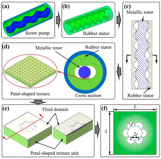
Figure 2.
Geometric model of petal-shaped micro-pit texture on the inside surface of stator rubber. (a) Screw pump model, (b) Stator rubber model, (c) Axial section view of the screw pump stator and rotor matching, (d) Screw pump stator and rotor with tangential section view, and (e,f) Petal-shaped micro-pit texture geometric parameters.
2.2. Mathematical Model of the Hydrodynamic Lubrication Flow Field for the Micro-Pit Textured Surface of the Stator Rubber in the Screw Pumps
The flow of shale oil in the petal-shaped micro-pit texture is affected by the Reynolds number (Re). Reynolds number is often used to describe the relationship between inertial force and viscous force. The Reynolds number of shale oil flow between the stator and rotor of screw pump can be calculated by Equation (2) [49,50].
where η is the dynamic viscosity of shale oil in kg/(m·s), ρ is the density of shale oil in kg/m3, h is the oil film thickness of the shale oil in m, U is the moving speed of the upper surface of oil film in m/s.
When the screw pump is in function, the stator rubber and metal rotor are kept in a high-pressure sealed condition. Under conditions of forced lubrication, a high-pressure lubricating oil film is established to avoid the rubber from potential damage. Consequently, it can be considered that the friction pair consisting of stator and rotor functions under fluid lubrication conditions. Based on fluid lubrication theory, the Reynolds equation for the fluid domain of the stator rubber texture is derived by neglecting the impacts of volumetric forces, inertial forces, and pressure variation in the oil film thickness direction, as delineated in Equation (3).
where p is the oil film pressure on the textured surface of the rubber stator in N, u and v are the relative velocities of the friction pair along the x and y coordinates in m/s, and Wh and W0 are the velocities of the two surfaces of the friction pair along the direction of oil film thickness in m/s.
By disregarding the influence of temperature and pressure on the actual viscosity of the shale oil, the Reynolds equation for the dynamic pressure oil film at the specific location of the stator-rotor friction pair can be formulated [51,52,53]. The Reynolds equation of the local pressure fluid film is shown in Equation (4).
The modified Reynolds equation for the theoretical model of rubber surface texture under incompressible laminar lubrication in narrow gaps can be produced by integrating the dynamic pressure effect factor.
The load-carrying capacity of the sliding surface can be determined by integrating the surface pressure of the oil film, as illustrated in Equation (6). By integrating the shear stress of the oil film surface, the friction force of the lubricating oil film may be derived, as illustrated Equation (7).
where τ is the shear force of the lubricating oil film in Pa, A is the effective area of rubber surface in m2, FW is the load-carrying capacity of oil film surface in N, and Fr is the friction force of the lubricating oil film in N.
The friction coefficient (f) of the oil film can be obtained by Equations (6) and (7), and the calculation formula is shown in Equation (8).
3. Simulation and Analysis of the Hydrodynamic Lubrication Flow Field of the Stator Rubber Petal-Shaped Micro-Pit Textured Surface
3.1. Simulation Model of the Hydrodynamic Lubrication Flow Field for Stator Rubber Textured Surface
Figure 3a illustrates the geometric model of the stator rubber with a petal-shaped micro-pit texture fluid domain, where h and h0 denoted the texture depth and oil film thickness. Fluent Meshing 2024 R2 was used to discretize the computational fluid domain, and a polyhedral mesh was employed. Figure 3b presents the meshing results for the fluid domain of the stator rubber petal-shaped micro-pit texture. It is important to mention that an appropriate mesh density for the computational domain is essential for ensure high precision of the simulation results. A very small mesh density cannot ensure high calculation accuracy. On the contrary, a very high mesh density increases the computation time and cost, and may negatively affect the convergence rate in the calculation process. Therefore, it was crucial to verify the mesh independence of the fluid domain on the textured surface of the stator rubber. The geometric model within the computational domain was complex. Thus, the mesh was systematically refined, yielding mesh numbers of 205,886, 285,544, 345,001, 478,610, and 758,380. The pressure distribution along the axis of the oil film bearing surface of the micro-pit petal-shaped texture was analyzed to evaluate the impact of mesh density on the calculation results. The results are illustrated in Figure 3c. It could be seen that, when the number of meshes exceeded 478,610, the numerical solution exhibited high stability and convergence. The pressure distribution along the axis of the oil film bearing surface of the micro-pit petal-shaped texture was highly consistent. When the number of meshes reached 345,001, the distribution showed a smaller error. Consequently, a mesh with a magnitude of 478,610 was chosen for calculations to ensure high precision and stability.
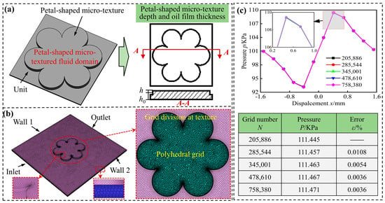
Figure 3.
Mesh generation and grid independence verification for the petal-shaped micro-pit textured fluid domain on the stator rubber inner wall. (a) Geometric parameters of fluid domain, (b) Fluid domain grid, and (c) Mesh independence verification.
The 3D model using the commercial CFD software Fluent 2024 R2 was employed for the analysis. A steady-state, double-precision solver based on pressure was selected for the simulation. Both the upper and bottom walls of the fluid domain were established with non-slip boundary conditions. The upper wall was set to translate in the x-direction with a velocity of 1 m/s, while the lower wall remained static. The inlet and outlet boundary conditions were defined as pressure boundaries. Discretization was performed using the second-order upwind, and the pressure-velocity coupling was achieved through the coupled algorithm. To improve the numerical simulation with actual working conditions, the lubricating medium for the stator-rotor friction pair was actual shale oil from a well. The shale oil had a density of 870 kg/m3 and a dynamic viscosity of 0.08 kg/(m·s).
3.2. Validation of the Dynamic Pressure Lubrication Flow Field Simulation Model of the Stator Rubber Textured Surface
The square pit texture model presented in reference [54] was numerically analyzed using the same method to verify the effectiveness of the numerical calculation method presented in this study. Figure 4a illustrates the fluid domain diagram from reference [54]. The side length of the fluid domain unit (Lr) and the side length of the square texture (b) were equal to 1 mm and 400 μm, respectively. The depth (h2), the oil film thickness (h1), the motion speed (ur), the lubricating oil density (ρr), and the viscosity (ηr) were equal to 10 μm, 50 μm, 6 m/s, 891 kg/m3, and 0.098 Pa·s, respectively. The oil film pressure data on the upper wall of the fluid domain were extracted. Figure 4b shows a comparison between the results obtained by the proposed approach and those obtained by the method presented in reference [54]. The analysis shows that the root mean square error (RSEM) between the calculated oil film pressure on the upper wall of the fluid domain using our model setting and the reference results is 0.03. It could be seen that the results of numerical calculation in this study were align well with existing in the reference results, and the pressure results were in good agreement, which verified the correctness and feasibility of the numerical calculation method in this study.
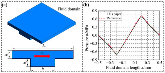
Figure 4.
Verification of simulation models and results in the reference. (a) The calculation domain model diagram in the reference and (b) Pressure comparison between this study and reference [54].
3.3. Analysis of the Hydrodynamic Lubrication Performance of Petal-Shaped Micro-Pit Texture Under Different Medium Flow Directions
The influence of the medium flow direction on the hydrodynamic lubrication performance of petal-shaped micro-pit textures was evaluated for the texture model with area ratio of 10% and a petal size of 400 μm. The medium flow direction of the medium was simulated for the directions following the x and y axes, as shown in Figure 5a. The pressure distribution of the oil film was consistent regardless of the inflow direction, as shown in Figure 5b. The distribution comprised a negative pressure zone followed by a positive pressure zone, with the area of the negative pressure zone being smaller than that of the positive pressure zone. It could be observed that the micro-pit petal-shaped texture generated net load-carrying capacity and exhibited high lubrication performance. The average and maximum pressures for different flow directions indicated that when the medium flowed from the y-direction, the average and maximum pressures generated by the oil film were higher than those observed for the flow in the x-direction, and compared with the non-textured surface, the oil film load-carrying capacity was increased by over 7.3%. This was due to that the resistance was lower and the flow is smoother in the y-direction. Compared with the x-direction, the y-direction mitigated turbulence upon contact with the texture, which made it more favorable.
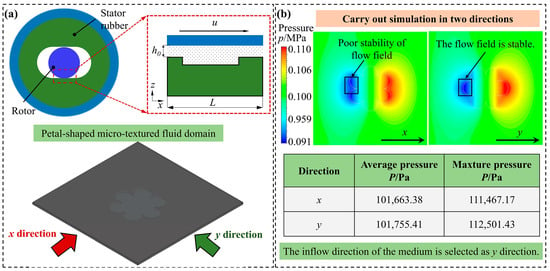
Figure 5.
Analysis of the results of the inflow direction of the medium. (a) The indication of the inflow direction of the medium, and (b) Analysis of oil film pressure cloud and pressure load-carrying capacity.
3.4. The Influence of the Size and Area Ratio of the Petal-Shaped Micro-Pit Texture on the Lubrication Performance of the Stator Rubber Surface
The size of the petal-shaped micro-pit texture exhibited a complex relationship with its area ratio. The oil film load-carrying capacity of the petal-shaped micro-pit texture with petal sizes of 150 μm, 250 μm and 350 μm was simulated and analyzed for different area ratios. Figure 6a,b illustrate the load-carrying capacity of the oil film on the petal-shaped micro-pit texture. It could be seen that when the petal-shaped micro-pit texture area ratio increased, the average pressure and maximum pressure on the oil film surface showed a decreasing trend. When the area ratio of petal-shaped micro-pit texture was 10%, the average pressure and maximum pressure on the oil film surface reached their maximum values. On the contrary, when the area ratio was 60%, the average pressure and maximum pressure on the oil film surface reached their minimum values. This was due to that, when the size of the petal-shaped micro-pit texture remained unchanged, the increase of area ratio resulted in a decreasing the size of the fluid domain, increasing the number of textures per unit area, and decreasing the texture spacing. The divergence and the convergence areas of the adjacent texture significantly interacted. That was, the convergence area of the previous round pit and the divergence area of the latter pit were partially eliminated. In addition, when the medium flowed through the petal-shaped micro-pit texture, the stability of the flow field decreased, which reduced the load-carrying capacity of the oil film. For the three sizes of petal-shaped micro-pit textures, the average pressure was decreased by 0.11%, 0.20% and 0.37%, while the maximum pressure decreased by 2.98%, 5.47% and 6.98%, respectively.
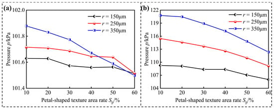
Figure 6.
Carrying capacity of oil films with micro-pit petal-shaped textures of different sizes as a function of area ratio. (a) Average pressure curve of oil film bearing surface and (b) The maximum pressure curve of oil film bearing surface.
Figure 7 illustrates the surface pressure of the oil film for different area ratios of the petal-shaped micro-pit texture with a size of 150 μm. It could be seen that the pressure distributions on the surface of the oil film were the same. After the medium flows through the petal-shaped micro-pit texture, a negative pressure zone was first formed, followed by a positiveone, which indicated that the hydrodynamic lubrication effect was generated in the pit area of the micro-pit petal-shaped texture. The positive pressure region of the upward lifting force produced by the lubricating oil in the pit area was greater than that of the negative pressure region, leading to a net pressure that increased the load-carrying capacity of the oil film. It could also be observed that, when the area ratio of the petal-shaped micro-pit texture increased, the load-carrying capacity of the oil film was gradually decreased.
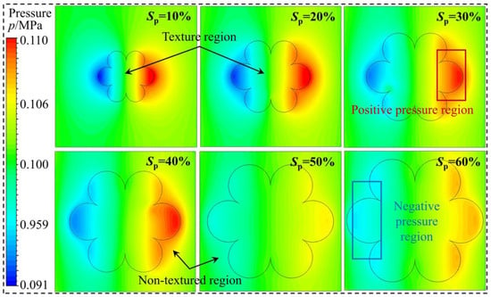
Figure 7.
Oil film pressure distribution of petal-shaped micro-pit texture for different area ratio conditions.
For the same texture density, the larger the texture diameter, the larger the average pressure and the maximum pressure. Figure 8 illustrates the pressure contours of the oil film surface for three sizes of petal-shaped micro-pit textures at area ratios of 10% and 20%. It could be seen the pressure of the textured surface was gradually increased from the negative pressure of the inlet area to the outlet area. The average pressure was much higher than the inlet area. Thus, it could be deduced that the size of the petal-shaped micro-pit texture, the areas of the positive and negative pressure regions, the net pressure on the oil film surface, and the oil film load-carrying capacity all increased. Therefore, a reasonable increase in the size of the petal-shaped micro-pit texture allowed to increase the load-carrying capacity of the oil film and yielded a higher dynamic lubrication performance effect.
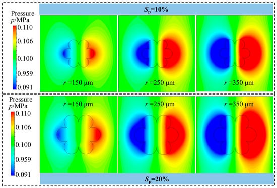
Figure 8.
Oil film pressure distribution of petal-shaped micro-pit texture for different size conditions.
4. Friction Tests of Petal-Shaped Micro-Pit Texture on the Surface of Stator Rubber
The petal-shaped micro-pit texture was manufactured on the surface of high acrylonitrile stator rubber using the LMS12 femtosecond laser manufacturing system, as shown in Figure 9a. Based on the results of the conducted simulation, the size and area ratio of the micro-pit petal-shaped texture were considered as the influencing factors to design the parameters of surface texture. Figure 9b illustrates the principle of processing micro-pit texture on the surface of high acrylonitrile stator rubber. The parameters for the surface texturing procedure using femtosecond laser are presented in Table 1. The processing parameters consisted of a wavelength of 1035 nm, a pulse width of 222 fs, a frequency of 800 kHz, a power of 800 mW, and a scanning speed of 100 mm/s. Scanning was performed only one time. The texture sizes were 150 μm, 250 μm and 350 μm, respectively. The surface densities were 10%, 20%, and 30%, respectively. After the laser processing was completed, the samples were ultrasonically cleaned with acetone and alcohol, and the processing was examined under a confocal microscope. Figure 9c illustrates the morphology of the texture after it was processed using the morphological profile measurement microscope.
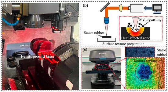
Figure 9.
The process involves creating a petal-shaped micro-pit texture on the surface of high-acrylonitrile stator rubber. (a) Femtosecond laser manufacturing system LMS12, (b) Laser micro-pit texture principle, and (c) Petal-shaped micro-pit textured surface morphology.

Table 1.
Processing surface texture process parameters of the femtosecond laser manufacturing system.
The tribological performance was evaluated using the UMT-3 friction and wear tester, as seen in Figure 10. The test environment consisted of a room temperature of 23 °C, an air relative humidity of 35%, and the test time was 1200 s. The used upper sample consisted of a stainless steel circle having a diameter of 20 mm. The sample was high acrylonitrile stator rubber having a Shore hardness of 70 HA. The rubber sample was fixed on the workbench by screws and positioning pins. The test load was set to 10 N, the shale oil actual well fluid was used as lubricating oil, the friction and wear tester had a reciprocating stroke of 12 mm, and the frequency was equal to 2 Hz. After the test was completed, the friction coefficient and wear depth curves were drawn based on the gathered discrete data, and the wear samples were subjected to ultrasonic cleaning with alcohol and acetone to remove the wear debris on the surface.
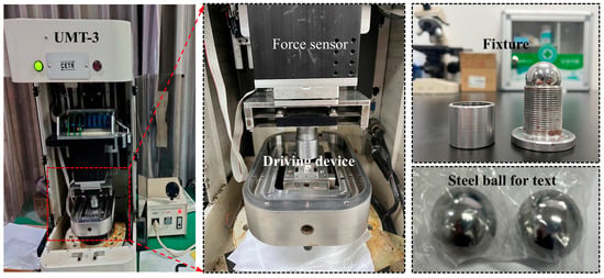
Figure 10.
UMT-3 friction and wear tester of petal-shaped micro-pit texture.
Figure 11a illustrates a texture sample with a petal-shaped micro-pit texture area ratio of 10%. Under a load of 10 N, the friction coefficient of different texture diameters changes over time. The texture sizes were 150 μm, 250 μm, and 350 μm, respectively. The surface friction coefficients of all three samples demonstrated a declining trend and reached a stable stage after 800 s. Throughout the entire wear test, the 150 μm texture showed a more significant decreasing trend, and the texture friction coefficient of 350 μm was always lower than that of the other two groups, showing the best wear reduction effect. In the initial wear stage, the friction coefficient was high, because the contact between the steel ball surface and the textured surface was not completely stable, and the surface texture did not give full play to the role of oil storage and accommodation of wear debris. With the extension of time, the oil film gradually formed, the ability of texture to store oil and capture wear debris increased, and the friction coefficient tended to be stable. By analysing the average friction coefficients of the three sizes of petal-shaped micro-pit textures, it could be observed that the average friction coefficient decreased as the texture size increased. The reason was that the larger size of micro-pits could store more lubricating oil and form a more complete oil film, so it showed the lowest average friction coefficient.
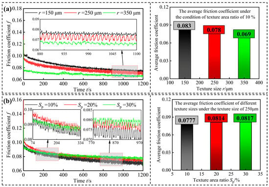
Figure 11.
Results of the petal-shaped micro-pit texture friction test on the stator rubber surface. (a) Friction curve and average friction coefficient under the condition of an area ratio of 10% and (b) Friction curve and average friction coefficient under a texture size of 250 μm.
Figure 11b shows the texture sample having a texture size of 250 μm. Under a load of 10 N, the friction coefficient fluctuates over time for different texturing area ratios. The area ratios were 10%, 20%, and 30%, respectively. It could be observed that the surface friction coefficient of all three samples exhibited a decreasing trend. The micro-pit petal-shaped texture, with an area ratio of 30%, initially demonstrated the lowest friction coefficient. After entering the stable stage, the texture friction coefficient with an area ratio of 10% was the smallest. Throughout the entire wear test, a larger area ratio corresponded to a higher friction coefficient. When the area ratio was 30%, the friction coefficient reached its maximum value; when the area ratio was 10%, it was at its minimum. In the early stage of friction, the friction coefficient fluctuated obviously, mainly due to the fact that the surface contact was not completely stable, and the fluctuation caused by the difference in bearing and lubrication between the texture area and the non-texture area. With the extension of time, the friction coefficient tended to be stable. Furthermore, it could be observed that, when the area ratio increased, the average friction coefficients of the three petal-shaped micro-pit texture samples also increased. The possible reason was that when the texture area ratio was large, the oil film formation and distribution were not uniform, resulting in an increase in the friction coefficient.
5. Conclusions
(1) The influence of coupling factors, such as medium flow direction, texture size, and the texture area ratio, on the lubrication performance of petal-shaped micro-pit textures was investigated based on the dynamic lubrication theory. A geometric model of the rubber petal-shaped micro-pit texture and a mathematical model of the dynamic lubrication flow field on the textured surface of the screw pump stator were developed.
(2) Compared to flow along the x-direction, when the medium flowed into the texture along the y-direction, the maximum pressure of the oil film increased by 0.93%. Moreover, the flow resistance was lower in the y-direction, resulting in enhanced stability of the flow field.
(3) A significant negative correlation was observed between the oil film load-carrying capacity and the area ratio. The average pressure reached its value at an area ratio of 10%. It was then reduced by almost 6% when the area ratio was increased to 60%. This was due to the interference of neighbouring flow fields induced by high-density textures, which reduced the dynamic pressure effect. At a fixed area ratio, when the texture diameter was increased from 150 μm to 350 μm, the load-carrying capacity of increased. A larger diameter also expanded the positive pressure zone, leading to the enhancement the hydrodynamic lubrication effect.
(4) In the friction and wear testing, the average friction coefficient of the 350 μm texture was 16.9% lower than that of the 150 μm texture. This demonstrated that the increase of the diameter resulted in substantially increasing anti-friction performance. When the texture size was fixed, the friction coefficient reached its minimum value at an area ratio of 10% and increased by 5% at an area ratio of 30%. The optimal parameters for the petal-shaped micro-pit texture were a texture size of 350 μm and an area ratio of 10%.
Author Contributions
Conceptualization, X.W., X.L., G.H. and X.S.; Methodology, X.W., X.L. and X.S.; Software, X.S.; Validation, X.W., X.L. and X.S.; Formal analysis, X.W., X.L., G.H., X.S., J.A., X.Y. and L.G.; Investigation, X.W., X.L., G.H., X.S., J.A., X.Y. and L.G.; Resources, X.L.; Data curation, X.W., X.L. and X.S.; Writing—original draft, X.W., X.L. and X.S.; Writing—review & editing, X.W., X.L. and X.S.; Supervision, X.W., X.L., G.H., J.A., X.Y. and L.G.; Project administration, X.W., X.L., G.H., X.S., J.A., X.Y. and L.G.; Funding acquisition, X.L. All authors have read and agreed to the published version of the manuscript.
Funding
Supported by National Science and Technology Major Project of China (Nos. SQ2025AAA120050 and SQ2025AAA120080), National Natural Science Foundation of China (Nos. 52074161 and 52005281), Taishan Scholar Project of Shandong Province (No. tsqn202211177), Natural Science Foundation of Shandong Province (Nos. ZR2022ME173 and ZR2023QE011), and Natural Science Foundation of Qingdao (No. 25-1-1-211-zyyd-jch).
Data Availability Statement
The raw data supporting the conclusions of this article will be made available by the authors on request.
Acknowledgments
The authors sincerely thanks to the anonymous reviewers for their insightful comments and suggestions.
Conflicts of Interest
The authors declare no competing financial interests.
References
- Liu, H.; Hao, Z.X.; Wang, L.G.; Cao, G. Current technical status and development trend of artificial lift. Acta Pet. Sin. 2015, 47, 1441–1448. [Google Scholar] [CrossRef]
- Zhou, J.; Xie, J.; Lu, L.; Sun, W.B. Multi-objective optimization of the structural parameters of an all-metal progressive cavity pump based on grey-taguchi relational analysis. J. Braz. Soc. Mech. Sci. Eng. 2025, 47, 299. [Google Scholar] [CrossRef]
- Wen, W.G.; Qin, J.Q.; Xu, X.R.; Mi, K.F.; Zhou, M. A model-driven approach to extract multi-source fault features of a screw pump. Processes 2024, 12, 2571. [Google Scholar] [CrossRef]
- Ramos, M.A.; Brown, J.C.; Rojas, M.; Kuyuco, O.; Flores, J.G. Producing extra-heavy oil from the Orinoco Belt, Cerro Negro Area, Venezuela, using bottom-drive progressive cavity pumps. SPE Prod. Oper. 2007, 22, 151–155. [Google Scholar] [CrossRef]
- Zhou, W.; Liu, X.F.; Wang, M.X.; Liu, C.H.; Hao, Z.X. A modern approach to the selection of electric submersible progressing cavity pumps for the pumping production systems. J. Braz. Soc. Mech. Sci. Eng. 2025, 47, 286. [Google Scholar] [CrossRef]
- Guagliano, M. Fatigue failure of a bar of a twin-screw extruder for plastics. Eng. Fail. Anal. 2004, 12, 950–962. [Google Scholar] [CrossRef]
- Borisova, K.; Ivanova, T.; Latypov, R. Study of screw pump stator and rotor working capacity to increase the output. Procedia Eng. 2017, 206, 688–691. [Google Scholar] [CrossRef]
- Chen, H.M.; Miao, C.W.; Lin, G.Y.; Yang, W.M.; Li, H.J. Design and optimization of the injection mold for rubber stators in oil production single-screw pumps. Polymers 2025, 17, 503. [Google Scholar] [CrossRef]
- Lv, X.R.; Wang, S.J.; Huo, X.Y. The effect of water content in crude oil on the tribological behavior of screw pump’s stator rubber. Chin. Sci. Bull. 2014, 59, 2868–2874. [Google Scholar] [CrossRef]
- Shi, C.S.; Zhu, X.H.; Chen, Y.K.; Tang, L.P. Failure analysis of general stator and uniform wall thickness stator. Eng. Fail. Anal. 2018, 94, 239–248. [Google Scholar] [CrossRef]
- Qian, C.; Li, Y.L.; Zhao, J.; Wang, S.J.; He, E.Q. Thermal-oxidative aging and tribological properties of carbon nanotube/nitrile butadiene rubber composites with varying acrylonitrile content: Molecular dynamics simulations. Polym. Eng. Sci. 2023, 63, 1516–1527. [Google Scholar] [CrossRef]
- Lv, X.R.; Wang, H.M.; Wang, S.J. Effect of swelling nitrile rubber in cyclohexane on its ageing, friction and wear characteristics. Wear 2015, 328–329, 414–421. [Google Scholar] [CrossRef]
- Yeo, Y.G.; Park, H.H.; Lee, C.S. A study on the characteristics of a rubber blend of fluorocarbon rubber and hydrogenated nitrile rubber. J. Ind. Eng. Chem. 2013, 19, 1540–1548. [Google Scholar] [CrossRef]
- Li, Y.F.; Nie, D.L.; Cai, Z.Q. The performance analysis of screw pump stator elastomers: Polyamide 6/hydrogenated nitrile blends: Mechanical, oil resistance and tribological properties. Polym. Test. 2023, 128, 108226. [Google Scholar] [CrossRef]
- Liu, X.F.; Shi, X.Z.; Hao, Z.X.; Wei, S.B.; Sun, Y.; Niu, X.L.; Li, M.; Li, Z.Z. Effect of complex well conditions on the swelling and tribological properties of high-acrylonitrile stator rubber in screw pumps. Polymers 2024, 16, 2036. [Google Scholar] [CrossRef]
- Naat, N.; Boutar, Y.; Naïmi, S.; Mezlini, S.; Akhavan-Safar, A.; Carbas, R.J.C.; Da Silva, L.F. Enhanced static and fatigue performance of FDM 3D-printed polycarbonate adhesive joints using bio-inspired surface textures. Eng. Fail. Anal. 2025, 176, 109626. [Google Scholar] [CrossRef]
- Zhao, X.D.; Zhang, Y.M.; Gao, S.Z. Analysis and evaluation of the synergistic effect of ceramic materials and surface texture on anti-abrasive particle wear under rolling conditions. Tribol. Int. 2024, 197, 109821. [Google Scholar] [CrossRef]
- Pawel, P.; Rafal, R.; Michal, W. Functional importance of surface texture parameters. Materials 2021, 14, 5326. [Google Scholar] [CrossRef] [PubMed]
- Bijani, D.; Deladi, E.L.; de Rooij, M.B.; Schipper, D.J. The influence of surface texturing on the frictional behaviour in starved lubricated parallel sliding contacts. Lubricants 2019, 7, 68. [Google Scholar] [CrossRef]
- Xia, S.Q.; Huang, C.; Ye, S.G.; Jiao, W.X.; Xia, Y.M. Study on the running-in tribological performance and mechanism of the valve plate with surface texture for axial piston pumps. Wear 2025, 574–575, 206085. [Google Scholar] [CrossRef]
- Wei, Y.; Yan, H.M.; Li, S.; Wang, X.M. Numerical and experimental study of a sector-shaped surface texture in friction reduction. Tribol. Lett. 2024, 72, 60. [Google Scholar] [CrossRef]
- Liu, X.F.; Liu, C.H.; Hou, G.X.; Guo, J.Y.; Hao, Z.X.; Shi, X.Z. Tribological behaviors of stator rubber with hexagonal micro-pit texture and enclosed groove of bionic honeycomb structure. iScience 2025, 28, 112421. [Google Scholar] [CrossRef] [PubMed]
- Shi, X.Z.; Liu, X.F.; Liu, C.H.; Hao, Z.X.; Huang, S.Z.; Sun, Y.; Niu, X.L. Numerical simulation of the lubrication performance of the stator and rotor friction pair surface rhombus-like texture in screw pumps. Lubricants 2025, 13, 157. [Google Scholar] [CrossRef]
- Zhang, J.J.; Zhang, J.G.; Rosenkranz, A.; Zhao, X.L.; Song, Y.L. Surface textures fabricated by laser surface texturing and diamond cutting-influence of texture depth on friction and wear. Adv. Eng. Mater. 2018, 20, 1700995. [Google Scholar] [CrossRef]
- Lu, C.; Ding, J.H.; Shi, P.Y.; Jia, J.H.; Xie, E.Q. Effects of texture density on the tribological properties of plasma electrolytic oxidation/polytetrafluoroethylene coatings formed on aluminum alloys. Macromol. Mater. Eng. 2021, 307, 2100678. [Google Scholar] [CrossRef]
- Li, D.; Yang, X.F.; Lu, C.Y.; Jian, C.; Wang, S.R. Tribological characteristics of a cemented carbide friction surface with chevron pattern micro-pit texture based on different texture density. Tribol. Int. 2020, 142, 106016. [Google Scholar] [CrossRef]
- Muchammad, M.; Hilmy, F.; Tauviqirrahman, M.; Jamari, J.; Schipper, D.J. CFD analysis of texture depth effect on the performance of hydrodynamic lubricated bearing. J. Phys. Conf. Ser. 2018, 1090, 012067. [Google Scholar] [CrossRef]
- Traore, M.M.; Wang, L. Influences of the flow speed and the micro-pit texture deepness on the dynamic lubrication performance characteristics. J. Comput. Theor. Nanosci. 2013, 10, 419–422. [Google Scholar] [CrossRef]
- Sheng, Z.W.; Zhu, H.; He, Y.; Shao, B.; Sheng, Z.; Wang, S.Q. Tribological effects of surface biomimetic micro-nano textures on metal cutting tools: A review. Biomimetics 2025, 10, 283. [Google Scholar] [CrossRef]
- Guo, Z.W.; Xie, X.; Yuan, C.Q.; Bai, X.Q. Study on influence of micro convex textures on tribological performances of UHMWPE material under the water-lubricated conditions. Wear 2019, 426–427, 1327–1335. [Google Scholar] [CrossRef]
- Li, M.; Shi, W.B.; Shi, J.; Wang, T.; Shi, L.P.; Wang, X.L. Regulation and control of wet friction of soft materials using surface texturing: A review. Friction 2023, 11, 333–353. [Google Scholar] [CrossRef]
- Tang, G.; Ho, J.K.; Dong, G.; Hua, M. Fabrication self-recovery bulge textures on TiNi shape memory alloy and its tribological properties in lubricated sliding. Tribol. Int. 2016, 96, 11–22. [Google Scholar] [CrossRef]
- Gherca, A.; Fatu, A.; Hajjam, M.; Maspeyrot, P. Influence of surface texturing on the hydrodynamic performance of a thrust bearing operating in steady-state and transient lubrication regime. Tribol. Int. 2016, 102, 305–318. [Google Scholar] [CrossRef]
- Guo, Z.W.; Yuan, C.Q.; Liu, P.; Peng, Z.X.; Yan, X.P. Study on influence of cylinder liner surface texture on lubrication performance for cylinder liner-piston ring components. Tribol. Lett. 2013, 51, 9–23. [Google Scholar] [CrossRef]
- Wang, Z.Q.; Ye, R.H.; Xiang, J.B. The performance of textured surface in friction reducing: A review. Tribol. Int. 2022, 177, 108010. [Google Scholar] [CrossRef]
- Ullah, M.Z.; Rizwan, M.; Raza, A.; Ahmed, A.; Abid, M. Effect of dimple shape and depth on tribological performance of textured surface. Int. Bhurban Conf. Appl. Sci. Technol. (IBCAST) 2021, 2021, 719–725. [Google Scholar] [CrossRef]
- Sasaki, S. Surface texturing for friction control: A review on existing technology and prospects: Review. Tribol. Online 2024, 19, 105–120. [Google Scholar] [CrossRef]
- Borghi, A.; Gualtieri, E.; Marchetto, D.; Moretti, L.; Valeri, S. Tribological effects of surface texturing on nitriding steel for high-performance engine applications. Wear 2008, 265, 1046–1051. [Google Scholar] [CrossRef]
- Wu, Z.; Bao, H.; Xing, Y.Q.; Liu, L. Tribological characteristics and advanced processing methods of textured surfaces: A review. Int. J. Adv. Manuf. Technol. 2021, 114, 1241–1277. [Google Scholar] [CrossRef]
- Zhang, H.; Hua, M.; Dong, G.Z.; Zhang, D.Y.; Chen, W.J.; Dong, G.N. Optimization of texture shape based on Genetic Algorithm under unidirectional sliding. Tribol. Int. 2017, 115, 222–232. [Google Scholar] [CrossRef]
- Yu, S.J.; Hu, X.J.; Cao, J.; Liu, L.; Huang, H.B.; Xie, Z.L.; Chen, X.Z.; Wang, X.C. Investigation of tribology and wear prediction of a polymer coating consisting of GO and WC on the surfaces of three textures. J. Mater. Sci. 2025, 60, 13765–13779. [Google Scholar] [CrossRef]
- Tang, X.S.; Lan, Y.F.; Bosiakov, S.; Zhuravkov, M.; He, T.; Xia, Y.; Lyu, Y.T. Investigation on the coupling effect of bionic micro-texture shape and distribution on the tribological performance of water-lubricated sliding bearings. Lubricants 2025, 13, 305. [Google Scholar] [CrossRef]
- Zhang, T.R.; Liu, C.L.; Li, X.M.; Guo, F.; Zhu, K.M. Fabrication of a composite groove array surface with gradient wettability which delivers enhanced lubrication performance. Lubricants 2025, 13, 193. [Google Scholar] [CrossRef]
- Jing, Z.G.; Jian, Y.S.; Guo, F.; Duan, P.H.; Wong, P.L.; Li, Z.Y. Surface wettability-driven oil film formation in slider-on-disc contact under limited lubrication. Friction 2025, 13, 9440990. [Google Scholar] [CrossRef]
- Uddin, M.; Liu, Y.W. Design and optimization of a new geometric texture shape for the enhancement of hydrodynamic lubrication performance of parallel slider surfaces. Biosurface Biotribology 2016, 2, 59–69. [Google Scholar] [CrossRef]
- Liu, X.F.; Sun, Y.; Liu, C.H.; Shi, X.Z.; Niu, X.L.; Zheng, G.; Wei, W.; Wei, S.B.; Huang, S.Z. Lubrication characteristics of a warhead-type irregular symmetric texture on the stator rubber surfaces of screw pumps. Lubricants 2024, 12, 397. [Google Scholar] [CrossRef]
- Jing, X.; Si, W.F.; Sun, J.; Zhou, J.K.; Lin, J.Q.; Yu, B.J.; Lu, M.M. Wettability and Droplet Directional spread investigation of crescent array surface inspired by slippery zone of nepenthes. Adv. Mater. Interfaces 2021, 9, 2101231. [Google Scholar] [CrossRef]
- Gui, C.; Meng, F.M. Comparative study of spherical dimple and bump effects on the tribological performances of journal bearing. Proc. Inst. Mech. Eng. Part J J. Eng. Tribol. 2019, 233, 139–157. [Google Scholar] [CrossRef]
- Li, K.M.; Jing, D.L.; Hu, J.; Ding, X.H.; Yao, Z.Q. Numerical investigation of the tribological performance of micro-dimple textured surfaces under hydrodynamic lubrication. Beilstein J. Nanotechnol. 2017, 8, 2324–2338. [Google Scholar] [CrossRef]
- Morris, N.J.; Shahmohamadi, H.; Rahmani, R.; Rahnejat, H.; Garner, C.P. Combined experimental and multiphase computational fluid dynamics analysis of surface textured journal bearings in mixed regime of lubrication. Lubr. Sci. 2018, 30, 161–173. [Google Scholar] [CrossRef]
- Lee, H.B.; Yeo, I.W.; Lee, K.K. The modified Reynolds equation for non-wetting fluid flow through a rough-walled rock fracture. Adv. Water Resour. 2013, 53, 242–249. [Google Scholar] [CrossRef]
- Pierart, G.F.; Santos, F.I. Steady state characteristics of an adjustable hybrid gas bearing-computational fluid dynamics, modified Reynolds equation and experimental validation. Proc. Inst. Mech. Eng. Part J J. Eng. Tribol. 2015, 229, 807–822. [Google Scholar] [CrossRef]
- Varela, C.A.; Santos, F.I. Validity of the modified Reynolds equation for incompressible active lubrication. Proc. Inst. Mech. Eng. Part J J. Eng. Tribol. 2016, 230, 1490–1502. [Google Scholar] [CrossRef]
- Wang, J.H.; Yan, Z.J.; Shen, Z.Y.; Pan, X.X. Three-dimensional CFD analysis of the influence of surface texture morphology parameters on lubrication performance. Lubr. Eng. 2021, 46, 37–43. [Google Scholar] [CrossRef]
Disclaimer/Publisher’s Note: The statements, opinions and data contained in all publications are solely those of the individual author(s) and contributor(s) and not of MDPI and/or the editor(s). MDPI and/or the editor(s) disclaim responsibility for any injury to people or property resulting from any ideas, methods, instructions or products referred to in the content. |
© 2025 by the authors. Licensee MDPI, Basel, Switzerland. This article is an open access article distributed under the terms and conditions of the Creative Commons Attribution (CC BY) license (https://creativecommons.org/licenses/by/4.0/).