You are currently viewing a new version of our website. To view the old version click .
Lubricants
  • Article
  • Open Access

13 November 2025

Dynamic Characteristics of Cylindrical Roller Bearing with Cage Pocket Deformation

,
,
,
,
and
1
School of Mechanical Engineering and Automation, Dalian Polytechnic University, Dalian 116034, China
2
College of Locomotive and Rolling Stock Engineering, Dalian Jiao Tong University, Dalian 116028, China
3
School of Mechanical Engineering, Dalian University of Technology, Dalian 116024, China
*
Authors to whom correspondence should be addressed.
Lubricants2025, 13(11), 495;https://doi.org/10.3390/lubricants13110495 
(registering DOI)

Abstract

Cage pocket beam deformation occurs due to susceptibility to impact loads under high-speed operating conditions and ultimately alters the bearing’s dynamic characteristics. Regarding the dynamics of localized cage deformation, rollers’ interactions, raceways, and a cage were incorporated, and a rigid–flexible coupled cylindrical roller bearing was modeled dynamically, considering localized cage deformation. The dynamic equations were solved using an adaptive variable-step BDF predictor–corrector algorithm to characterize the behavior of the bearing system. Localized deformations of the cage affected the dynamic characteristics of the bearing. The results show that the cage beams deformed, which increased the local clearance between rollers to a certain extent and was beneficial for the stability of roller motion. However, further increases in clearance can induce roller slippage, suggesting that changes in local clearance are the primary cause of roller slippage.

1. Introduction

The cylindrical roller bearing cage, which is designed as a thin-walled structure featuring a grid-like framework with multiple pockets, plays a vital role in maintaining the relative spatial positioning and operational orientation of rolling elements. Owing to machining inaccuracies and the intricate loading conditions during high-speed operation, the cage pockets in roller bearings are prone to deformation and even plastic deformation in the pocket-supporting beam structure. Cage pocket deformation not only modifies the clearance between the cage and the rollers and undermines the symmetry of the cage’s mass distribution, but it also directly affects the bearing’s dynamic characteristics. Therefore, the dynamic characteristics of cylindrical roller bearings with cage pocket deformation are of great significance for theoretical research and the structural optimization of the cage.
At present, significant progress has been made in the study of bearing dynamics, Ghaisas [] developed a six-degree-of-freedom dynamic model of the cage based on Hertz contact theory, through which instability was revealed to be governed primarily by the clearances among the rollers, raceways, and the cage. Kumbar S G [] reviewed the evolution of dynamic modeling for rolling bearings, encompassing early quasi-static models and modern full-degree-of-freedom dynamic models, and emphasized that global coordinate systems significantly enhance modeling accuracy and adaptability. Gao [] developed an explicit dynamic modeling approach that incorporates friction effects at connection interfaces, thereby significantly reducing the computational complexity of multibody systems and enhancing the accuracy of constraint force solutions in friction modeling. Pesterev D [] proposed a hybrid numerical integration scheme, which combines a precise integration method with the Adams–Bashforth–Moulton algorithm, thereby improving the efficiency of solving stiff dynamic equations. Jia Jiaxin [] incorporated the flexibility of the cage pocket into a dynamic model of cylindrical ball bearings, enabling a quantitative assessment of the effects of dimensional deviations, which were shown to cause significant changes in the bearing’s dynamic performance. Long Zhang [] investigated rolling bearings with outer ring faults and demonstrated that crack propagation initiates at the fault exit edge, where the propagation rate accelerates as the fault severity increases. Yang [] elucidated the influence of crack parameters on bearing dynamics and service life and further demonstrated the mechanism of crack propagation, while Qiang Chen [] attributed bearing ring fractures to high residual stresses in regions of stress concentration. Further studies confirmed that crack depth, orientation, and location significantly affect bearing dynamic behavior and crack propagation throughout the bearing’s life. Hui Li [] established a dynamic model of a ball bearing with a fractured cage by analyzing the complex interactions among its components and performed dynamic simulations using a variable-step Runge–Kutta integration method, demonstrating that cage fracture induces unstable cage trajectories and significantly increases vibration amplitudes. Complementary experimental studies by Wen et al. [] demonstrated that cage whirl orbits evolve from irregular to stable forms as pocket clearance increases, resulting in complex frequency characteristics. Hao Chen [] used the lumped-mass method to model cylindrical roller bearings with flexible cages, considering the flexibility of the crossbeam and side beam. He compared rigid and flexible cages, analyzed cage centroid collisions and trajectories, and examined the effects of different beam flexibilities and clearance ratios. Dai P. [] validated the operating mechanism of defective bearing raceways through experiments, showing that local raceway imperfections enhance the impact magnitude and frequency between the rollers and the raceway, while diminishing cage–raceway collisions and increasing sliding behavior. A new numerical simulation method for analyzing the crack propagation mechanism and crack angle of locally fractured cages in double-row cylindrical roller bearings was developed by Long Qing Fan []; this not only captures the dynamics of the faulty bearing more accurately but also provides deeper insight into the dynamic effects induced by failure. Zarei A [] constructed a theoretical model to predict the roller push-out force in polymer cages with varying materials and groove shapes, representing cage deformation as a parabolic cantilever beam. Experimental validation confirmed the model’s accuracy using a fixed coefficient across different geometries and materials. Collectively, these studies investigate the unstable cage whirling mechanism. They also look at the dynamic properties. This is performed from the perspective of dynamic modeling and cage movement evaluation. The studies consider various factors. Additionally, some scholars have examined the theory of cage flexibilization. Pederson [] first introduced the lumped-mass method to construct flexible cage models, revealing that rigid models overestimate pocket–roller contact forces by 44%. Weinzapfel and Sadeghi [] used a discrete element meshing method to model the structure and analyze its flexibility. This method was shown to effectively reduce the transient collision behavior of the ball–pocket interface. Shuai Jun Ma [] developed a semi-flexible dynamic model under force excitation, revealing that preload conditions significantly affect cage orbital radii and motion stability, with flexible models producing results closer to experimental observations compared with rigid models. Liu et al. [] divided a cage into multiple discrete mass units connected by springs, representing cage flexibility through spring stiffness, and evaluated contact characteristics by varying the stiffness values. Ming kai Wang [] modeled cage flexibility by discretizing the cage into multiple discrete segments connected with nonlinear springs and developed an integrated dynamic model of ball bearings accounting for structural flexible deformation. The study examined the effect of cage flexibility on cage clearance, revealing that cage flexibility is more sensitive to centrifugal effects under lower-elastic-modulus conditions [].
Current research on cage fracture primarily focuses on the mechanisms of crack initiation and propagation, while limited attention has been given to the influence of local cage deformation, particularly the effects of single-location deformation of the cage crossbeam or side beam on the overall bearing performance.
A dynamic model of cylindrical roller bearings that incorporate local cage pocket deformation was developed. The dynamic responses of the cage under various crossbeam and side beam deformation conditions were analyzed systematically, and the corresponding influence mechanisms on the bearing system were elucidated. The results reveal that cage deformation significantly affects the overall load-carrying performance and provides theoretical support for developing deformation control strategies.

2. Rigid–Flexible Coupled Dynamic Model of a Cylindrical Roller Bearing

2.1. Dynamic Characterization of Cage Localized Deformation

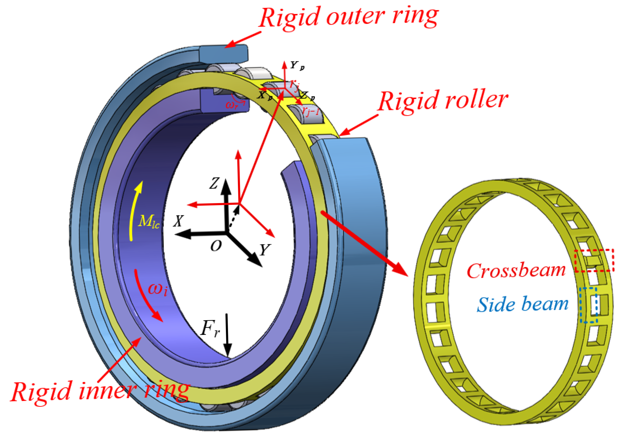
Under high-speed operation, bearings are subjected to impact loads or complex forces that may induce transient interactions between the rollers and the cage, causing localized deformation, particularly at the cage pockets, which readily leads to roller jamming and slipping and thus affects the overall dynamic characteristics of the bearing. The established dynamic model of the cylindrical roller bearing cage is shown in Figure 1 [], in which the positions of the cage crossbeam and side beam are clearly indicated; F r represents the radial force acting on the inner ring of the bearing, and ω i is the bearing’s inner ring speed. ω r is the rotation speed of the roller; M l c is the torque; O is the bearing coordinate system; and O p is the roller coordinate system. The bearing inner ring rotates about the x-axis.
Figure 1. Model of the bearing coordinate system.

2.1.1. Model Assumptions

Under the following assumptions, a rigid–flexible coupled dynamic model of a cylindrical roller bearing exhibiting local cage deformation was developed.
All internal components, except the cage, are treated as rigid bodies, with their centers of mass assumed to coincide with the geometric centers, while only the flexibility of the cage is considered. The cage pocket is idealized as a rectangular structure for computational convenience, while the thermal effects of material properties are neglected. It is further assumed that the cage maintains a constant volume under small deformations of the crossbeam and side beam, implying that the elastic deformation satisfies the approximate condition of negligible volumetric change.
Since the local deformation of the cage defined in the model is based on an idealized flexible assumption, certain discrepancies still exist between the modeled deformation state of the cage beams and the actual operating conditions.

2.1.2. Cage Local Deformation Characterization

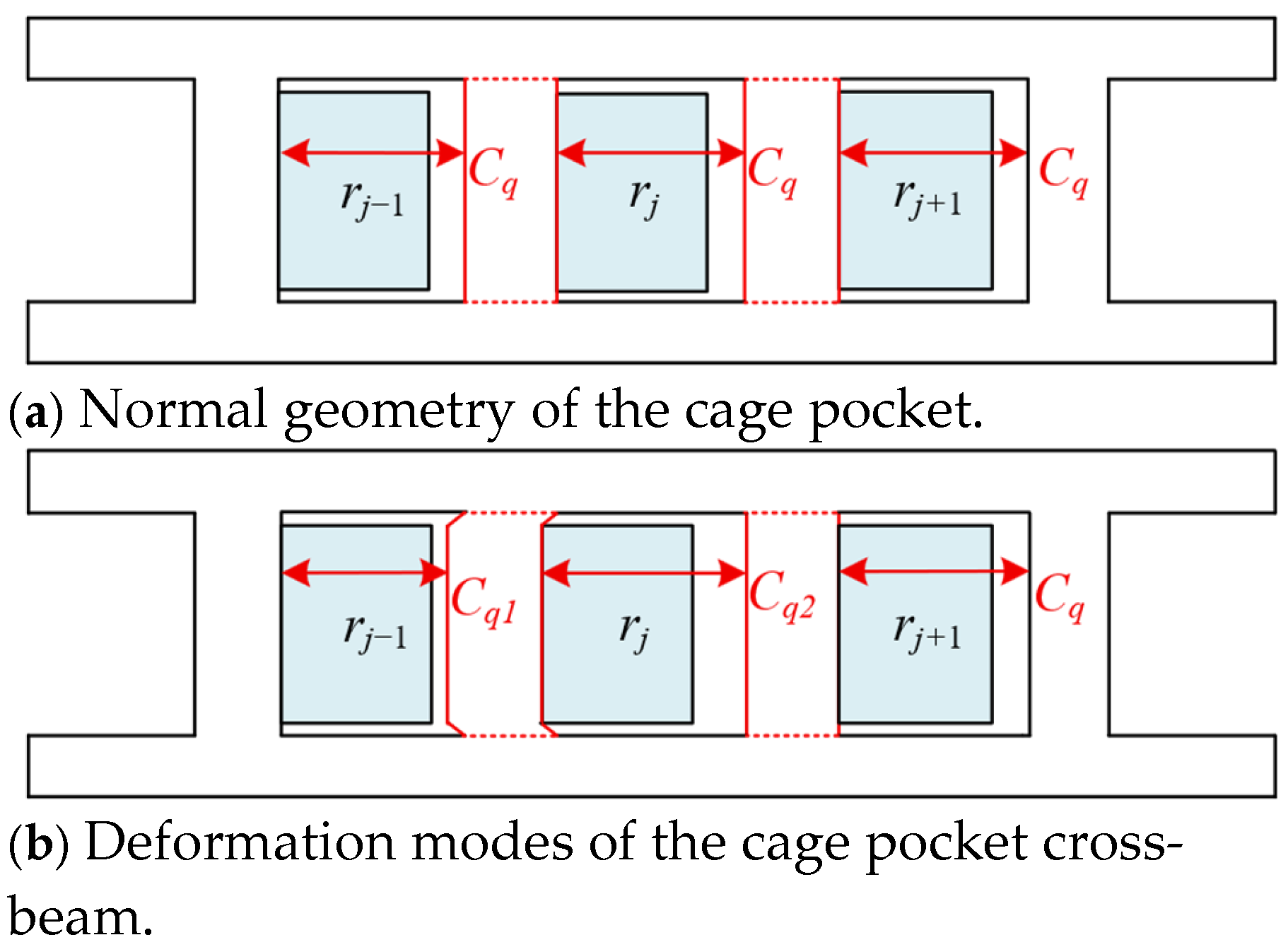
The nominal circumferential diameter of the pocket is specified as C q . When the deformation occurs in the cage pocket crossbeam, the circumferential diameter associated with roller r j 1 is reduced from C q to C q 1 , while that associated with roller r j is increased from C q to C q 2 , as illustrated in Figure 2. C q is the nominal clearance of the r j + 1 roller pocket; C q 1 is the size of the r j 1 roller after being compressed; C q 1 is the clearance of the r j roller pocket; and C q to C q 1 are assumed to be ideal dimensions.
Figure 2. Characterization of cage pocket crossbeam deformation.
The deformation amount of the cage pocket crossbeam is expressed as δ q .
δ q = C q C q 1 = C q 2 C q
To better reflect actual deformation conditions, deformation faults of δ q = 0.1   mm and δ q = 0.2   mm were selected for analysis.
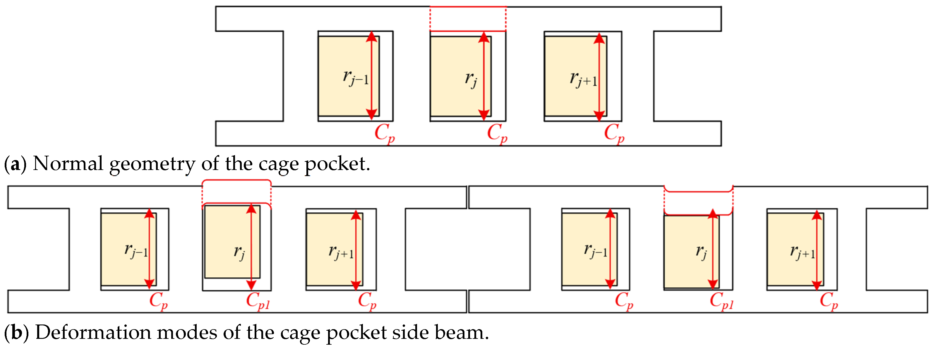
The length of a normal cage pocket is denoted as C p . When positive deformation occurs in the side beam of the cage pocket, the pocket length of roller r j is increased from C p to C p 1 . When negative deformation occurs in the side beam of the cage pocket, the pocket length of roller r j is decreased from C p to C p 1 , as illustrated in Figure 3. C p 1 is the pocket length of roller r j after side beam deformation.
Figure 3. Characterization of cage pocket side beam deformation.
The deformation amount of the cage pocket side beam is expressed as δ p . Deformation faults of δ p = + 0.3   mm and δ p = 0.3   mm were specifically selected for analysis.
δ p = C p 1 C p

2.2. Rigid–Flexible Dynamic Model of a Cylindrical Roller Bearing Considering Cage Deformation

A cylindrical roller bearing was modeled using a rigid–flexible coupled dynamic approach that incorporated the local deformation characteristics of the cage. This approach was developed based on rigid-body multibody dynamics and the finite element method. The bearing rings and rollers were modeled as rigid bodies, whereas the cage was treated as a flexible body to capture its deformation characteristics. The key factors influencing cage pocket deformation faults were systematically investigated, and the mechanisms through which such deformations affected the bearing’s overall performance were elucidated.
Contact pairs are formed to restrict the contact surfaces between the outer ring of the bearing and the bearing socket, including those between the inner ring and the rolling elements, between the outer ring and the rolling elements, and between the rolling elements and the cage, through which the interaction forces between the rollers and raceways were determined.
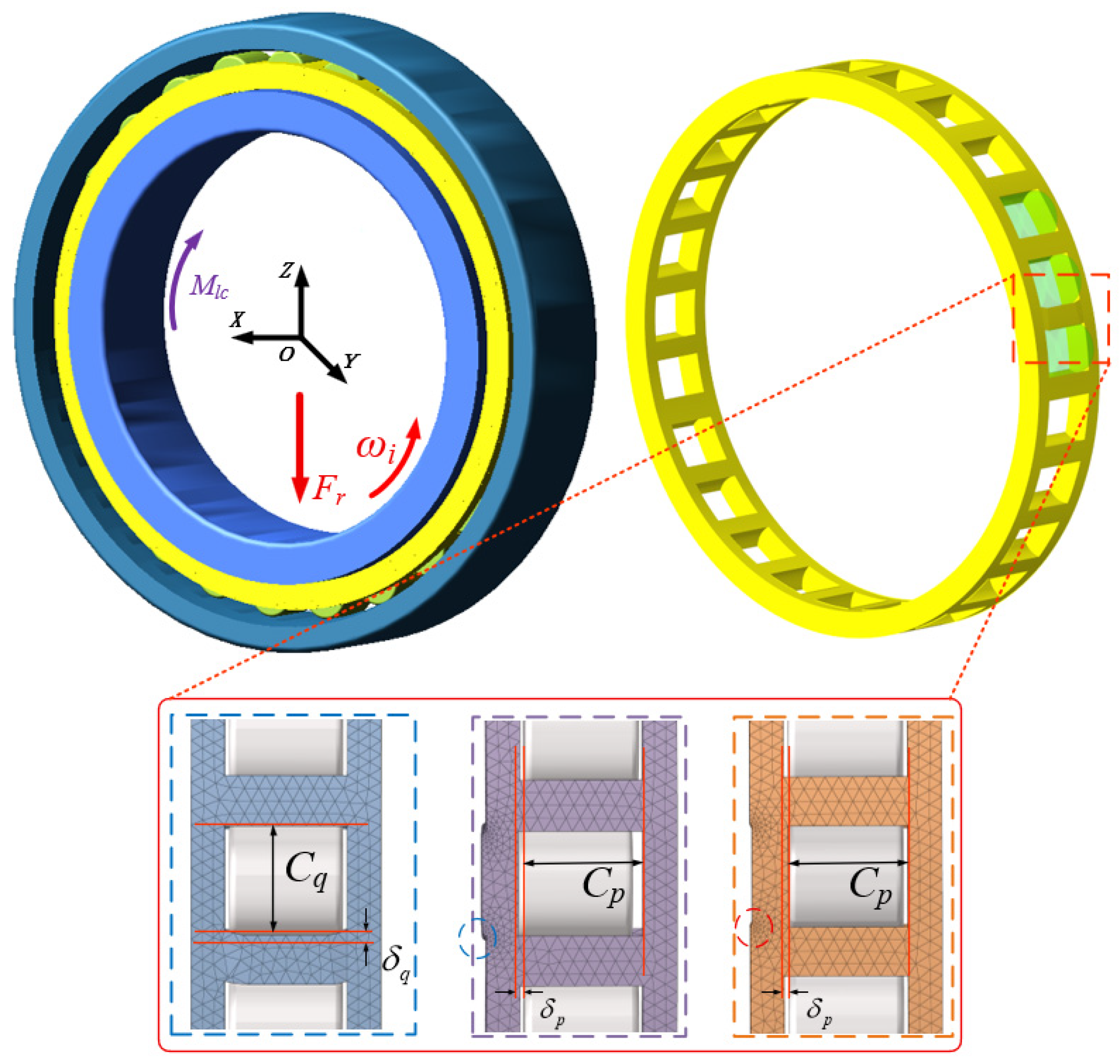
A flexible cage was modeled in Hyper Mesh using Solid185 elements with standard tetrahedral meshing. In the normal flexible cage model, a total of 377,400 mesh elements and 87,014 nodes were produced. In the model incorporating deformations of the cage crossbeam and side beam, 395,692 and 386,950 mesh elements were generated, with 98,015 and 94,256 nodes, respectively. The finite element mesh model, constructed via the discrete element method, is illustrated in Figure 4. In Figure 4, the blue-circled areas correspond to the positive deformation of the cage side beam, whereas the red-circled areas correspond to the negative deformation.
Figure 4. Rigid–flexible coupled dynamic model of bearings.
The tetrahedral mesh was selected because it offers strong geometric adaptability, allowing for a more accurate representation of the complex curved surfaces of the cage pocket under small deformations. Compared with hexahedral meshes, tetrahedral elements are easier to implement for automatic meshing and local refinement in irregular geometric regions. This effectively improved the mesh accuracy in contact areas, thereby enabling more precise simulation of the contact characteristics among the rollers, cage, and raceways.
C q is pocket width; C p is pocket length; δ q is crossbeam deformation; and δ p is side beam deformation.

2.2.1. Interaction Forces Among Bearing Components

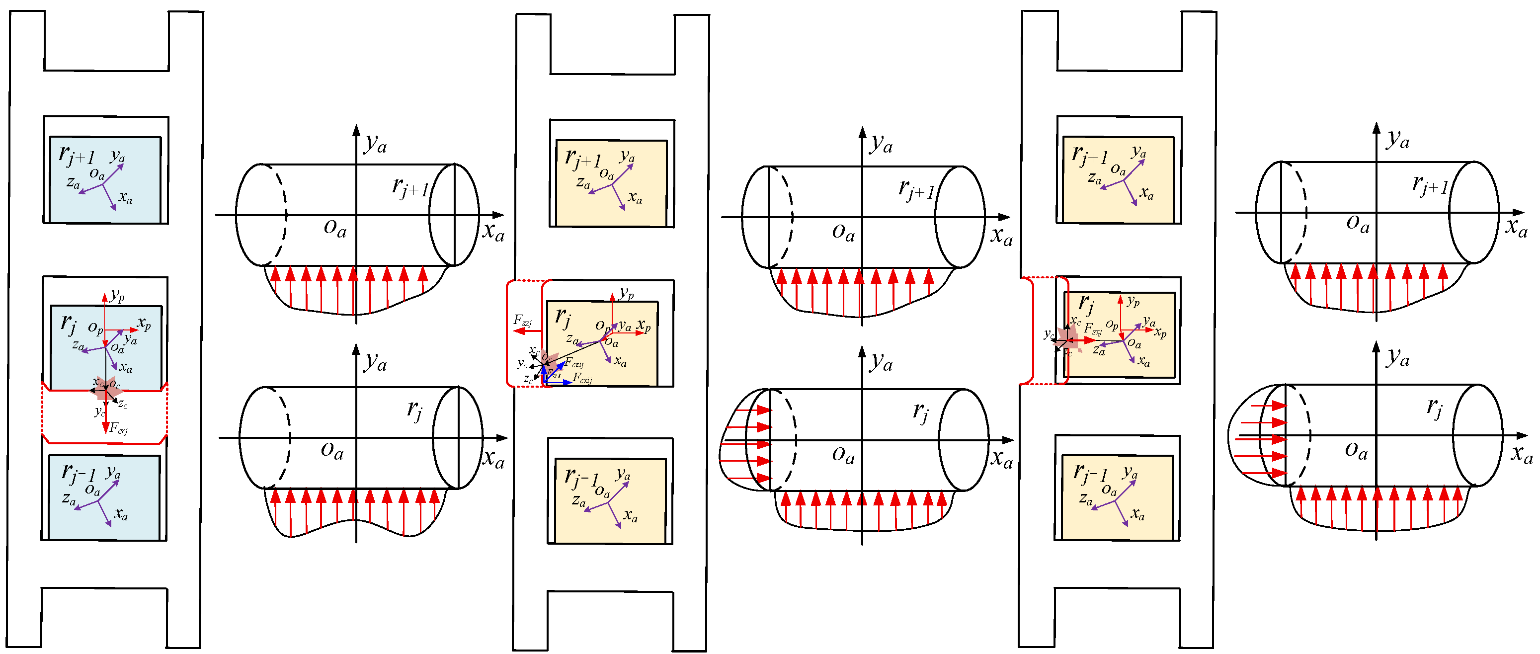
The model presented in this paper was developed based on previous studies [,], with several improvements incorporated to enable the characterization of local deformations at cage pocket positions. The geometry and stress distribution of the rollers corresponding to different cage pocket deformation locations are depicted in Figure 5.
Figure 5. Position relationship and stress distribution between the cage and rollers after deformation of the cage pocket beam.
In the rigid–flexible coupled dynamic model, each roller is modeled as a rigid body with six degrees of freedom (three translational and three rotational), enabling the representation of multi-degree-of-freedom spatial contact behavior. The interaction between the roller and the cage pocket is modeled through the implementation of a three-dimensional, nonlinear contact formulation within the dynamic analysis framework. This formulation captures variations in contact forces and motion characteristics caused by roller tilting and skewing. Thus, the effects of roller tilting are included in the dynamic computation and influence the cage forces and trajectories observed in the simulation results. The red arrows indicate the stress distribution experienced by the rollers.
The principal aim of the present study is to illuminate the stresses and contact states of the rollers under deformations of the cage, crossbeam, or side beam. However, the rollers do not merely move along the edges of the cage pockets during operation.
O p denotes the cage pocket center coordinate, O a denotes the roller center coordinate, and O c denotes the collision point coordinate.
During normal operation, stress is uniformly distributed along one side of a roller’s contact end when the roller contacts the cage. The structure is altered by deformation of the cage pocket, causing the roller–cage contact position to shift and producing elevated stress at both edges of the roller while reducing stress in the central region. In addition, deformation of the cage pocket side beam modifies the pocket length, increasing the probability that the roller engages the deformed region of the side beam and generating corresponding contact stresses.
This is based on the contact relationships observed among the bearing components. The differential equations governing the cage dynamics were established [], and the contact loads between the components were calculated by capturing the time-varying penetration quantity o i o j ¯ . The method used to obtain these variables was maintained consistently with that reported in the literature []. According to Hertz contact theory, the normal contact force acting between the j roller and the inner raceway is denoted as F i j .
F i j = K i j o i o j ¯
F i j denotes the damping coefficient, and K i j [] denotes the contact stiffness.
The contact stiffness between the roller and the inner raceway [,] is denoted by K i j , and the calculation of the contact force, as well as the traction force on the inner raceway surface, is determined using the same procedure [].

2.2.2. Roller Slip Ratio Calculation

Cage pocket crossbeam and side beam deformation, which occur at various positions and under different conditions, can result in roller instability and slip.
The slip ratio S r of the roller is calculated as
S r = n r t h n r n r t h × 100 %
where n r t h is the peripheral velocity of the roller and n r is the velocity of the corresponding raceway.

2.3. Rigid–Flexible Coupling Dynamics Theory

2.3.1. Flexible Treatment of Cage

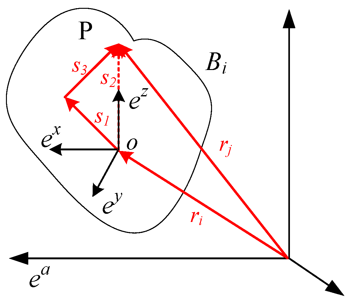
The inertial frame is considered fixed in space. The moving frame is attached to the flexible body and undergoes motion with its translational and rotational displacements. The reference configuration is defined by the position and orientation of the moving frame relative to the fixed inertial frame. The position coordinate system of node P within the flexible body is shown in Figure 6, with a fixed inertial frame ( e a ) and a moving frame ( e x ).
Figure 6. Location of node P in a flexible body.

2.3.2. Velocity and Acceleration of Flexible Body at Arbitrary Points

In the analysis of planar motion of flexible bodies with small deformations, the motion is typically decomposed into three sequential stages: rigid-body translation, rigid-body rotation, and elastic deformation. And the volumetric change in the cage crossbeam or side beam under small deformations is neglected. Therefore, the velocity and acceleration of the flexible cage are computed using the following elastic deformation formulas. The position vector of an arbitrary point on the flexible body in space is expressed as follows:
r = r i + a s i + Δ
The symbol r is employed to denote the position vector of the point P within the bearing inertial coordinate system. r i corresponds to the position vector of the origin of the cage floating coordinate system relative to the bearing inertial frame; a is the direction cosine matrix; S i is the position vector of point P within the floating reference frame of the undeformed cage; and Δ denotes the relative deformation vector, which is expressed as follows:
Δ = Φ q q f
where Φ q corresponds to the assumed deformation mode matrix of a point that fulfills the Ritz basis vector criterion and q f is the generalized deformation coordinate.
By taking the first- and second-order derivatives of the following expression, it is possible to obtain the velocity and acceleration vectors at any point on the flexible body.
r ˙ p = r ˙ 0 + a ˙ s p + u p + a Φ q q ˙ f r ¨ p = r ¨ 0 + a ¨ s i + Δ + 2 a ˙ Φ q q ˙ f + a Φ q q ¨ f
r ˙ p represents the velocity of the flexible body, and r ¨ p represents the acceleration of the flexible body.

2.3.3. Rigid–Flexible Coupling Motion Equations

In the present study, the rigid cage is treated as a flexible structure, and the corresponding boundary conditions are imposed accordingly. When the rigid–flexible coupling system is solved, a corresponding generalized coordinate system needs to be established. Following Adams the Cartesian coordinates of the rigid body’s center of mass and the generalized Euler angles representing the rigid body’s orientation are adopted as the generalized coordinates, which are expressed as follows:
q i = x , y , z , ψ , θ , φ i T , q = q 1 T , q 2 T , , q n T T
The system’s equations of motion are established using the Lagrange multiplier method.
d d t T q ˙ T T q T + f q T ρ + g q T μ Q = 0
The constraint equation is as follows:
g q , q ˙ , t = 0
T is defined as the kinetic energy of the system. Q is defined as the generalized force of the system. q ˙ is defined as the generalized velocity array. ρ and μ represent the complete and partial constraint matrices, respectively.
In simulating the bearing motion, the Newton–Raphson algorithm is employed to iteratively determine the position of t n at a given time according to the complete constraint algebraic equation.
f q | k Δ q k = f q k , t n
The instantaneous velocity and acceleration of the constraint equation at time t n are as follows:
f q q ˙ = f t f q q ¨ = q ˙ 2 f t 2 + j = 1 n t = 1 n 2 f q j q i q ˙ i q ˙ j + t f q q ˙ + q f t

3. Dynamic Analysis of Cylindrical Roller Bearing Under Cage Localized Deformation

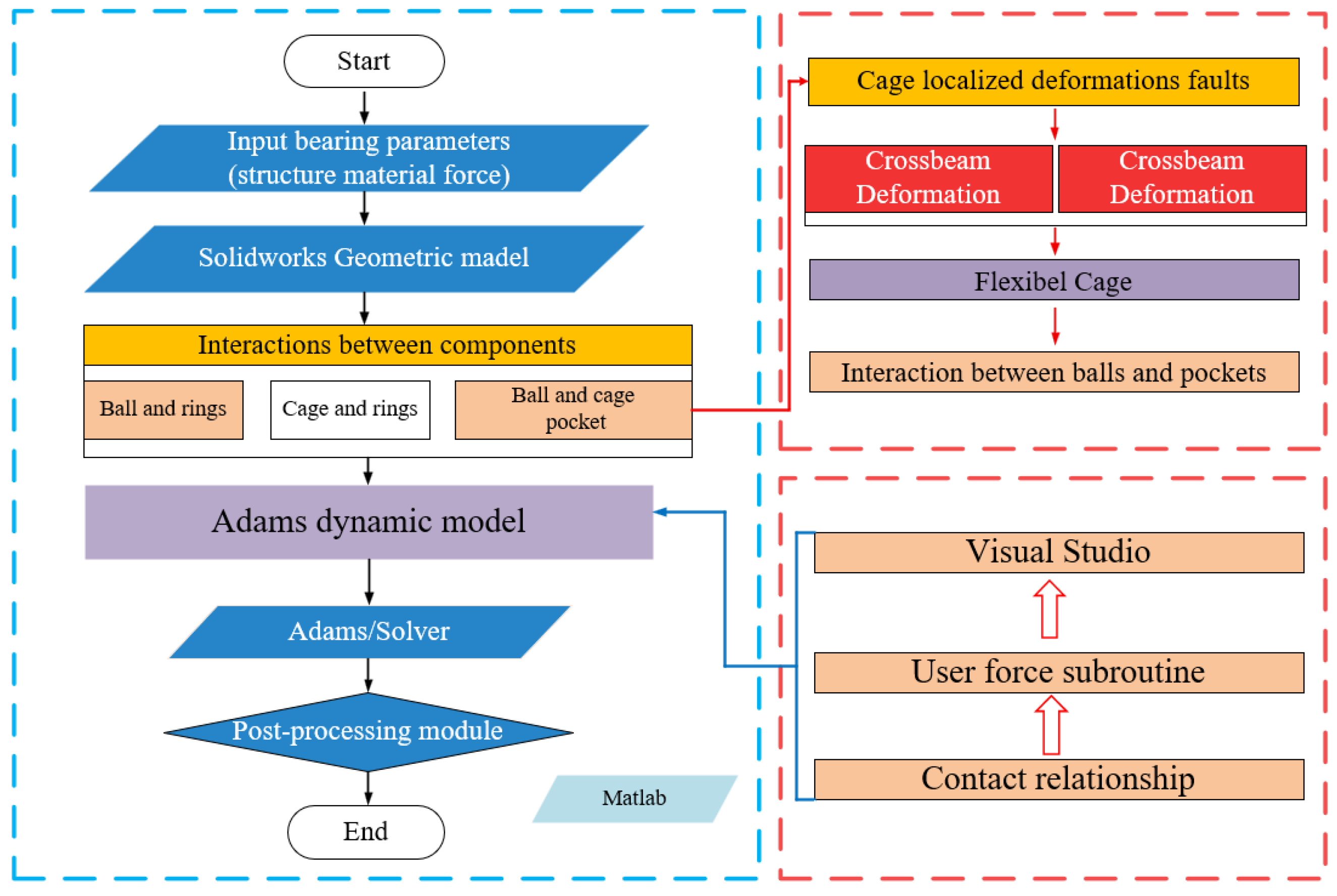
Figure 7 illustrates the dynamic modeling procedure of the cylindrical roller bearing with localized cage pocket deformation. First, the bearing geometry was constructed. Then, the cage with localized deformation features was established as a flexible body using the Solid185 element in Hyper Mesh and subsequently imported into Adams. The material properties of each component were assigned, and the boundary conditions were specified: the outer ring was fixed, a point drive constraint was applied to the inner ring, and a radial load was imposed to simulate operational conditions. Finally, the system was solved numerically using a modified Newton–Raphson method combined with a variable-order, variable-step Backward Differentiation Formula algorithm. The simulation outcomes could subsequently be viewed within the designated post-processing module.
Figure 7. Dynamic modeling procedure of cylindrical roller bearings with cage deformation faults.

3.1. Influence of Cage Pocket Crossbeam Deformation on the Dynamic Characteristics of Bearings

The N1013 cylindrical roller bearing was selected for modeling and analysis. The bearing rings and rollers were fabricated with GCr15 bearing steel, while the cage was composed of brass. The corresponding material properties are summarized in Table 1.
Table 1. Material parameters of bearing components.
To clarify the influence of localized cage pocket deformation on the dynamic characteristics of the bearing, a coupled rigid–flexible dynamic model was developed for a cylindrical roller bearing, accounting for localized deformations in the cage crossbeam and side beam. The impact-induced local deformation of the cage pocket was analyzed for its effects on cage–roller clearance, roller–cage interactions, and cage motion characteristic curves and equivalent stress.
To further examine the impact of cage pocket crossbeam deformation on the dynamic characteristics of the cylindrical roller bearing, the crossbeam at the roller–contact end of roller r j was selected for analysis. The deformation levels of the cage crossbeam, denoted as δ q = 0.0   mm , δ q = 0.1   mm , and δ q = 0.2   mm , were selected for dynamic analysis, providing a closer representation of the actual beam deformations. The speed of the bearing inner ring was set to 6000 r/min, and a radial load of 1000 N was applied.
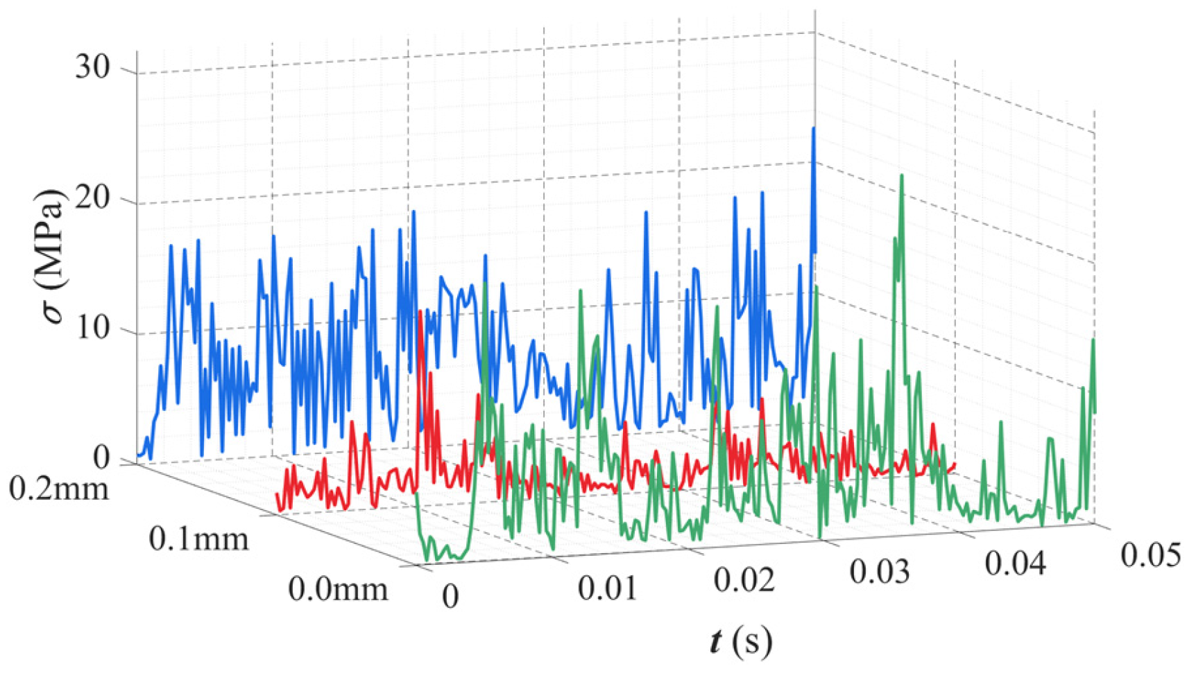
Figure 8 illustrates the equivalent stress of the cage for three crossbeam deformation states, with deformation magnitudes of 0.0 mm, 0.1 mm, and 0.2 mm, respectively. The equivalent stress increases progressively with the severity of deformation, which is caused by the enlarged cage pocket clearance resulting from crossbeam deformation, amplifying the impact forces exerted by the rollers on the cage.
Figure 8. Equivalent stress curve of the cage under crossbeam deformation.
The radial displacement of the cage centroid under crossbeam deformation conditions is shown in Figure 9. The increasing crossbeam deformation alters the cage’s radial displacement behavior. With rising deformation severity, the vibration amplitude initially increases and then decreases. This pronounced radial vibration of the cage occurs When the crossbeam deformation is 0.2 mm, as the r j 1 roller is squeezed against the cage.
Figure 9. Radial displacement of the cage centroid under crossbeam deformation.
The motion trajectories of the cage centroid under cage pocket crossbeam deformation are shown in Figure 10 The results indicate that as crossbeam deformation increases, the trajectory becomes more dispersed, and the whirl radius gradually expands before stabilizing within a certain range. However, once the deformation exceeds 0.2 mm, the whirl radius then begins to decrease, which ultimately results in slip, and the instability of the r j 1 roller is caused by severe deformation.
Figure 10. Trajectory of the cage centroid with crossbeam deformation.
When the cage is undeformed, the vibration acceleration amplitude of the outer ring remains within a relatively stable range, as shown in Figure 11. However, once cage pocket crossbeam deformation occurs, the amplitude exhibits sudden and irregular spikes, indicating that local cage deformation disrupts the stability of outer ring vibrations.
Figure 11. Vibration acceleration of the outer ring under deformation of the cage crossbeam.
Figure 12 presents the rotational speed of the cage under different cage pocket crossbeam deformation conditions. The deformation of δ q = 0.1   mm has a negligible effect on the cage rotational speed. However, when the deformation extends to δ q = 0.2   mm , the amplitude of rotational speed fluctuations increases markedly, accompanied by a significant rise in vibration frequency.
Figure 12. Rotational speed of the cage with crossbeam deformation.
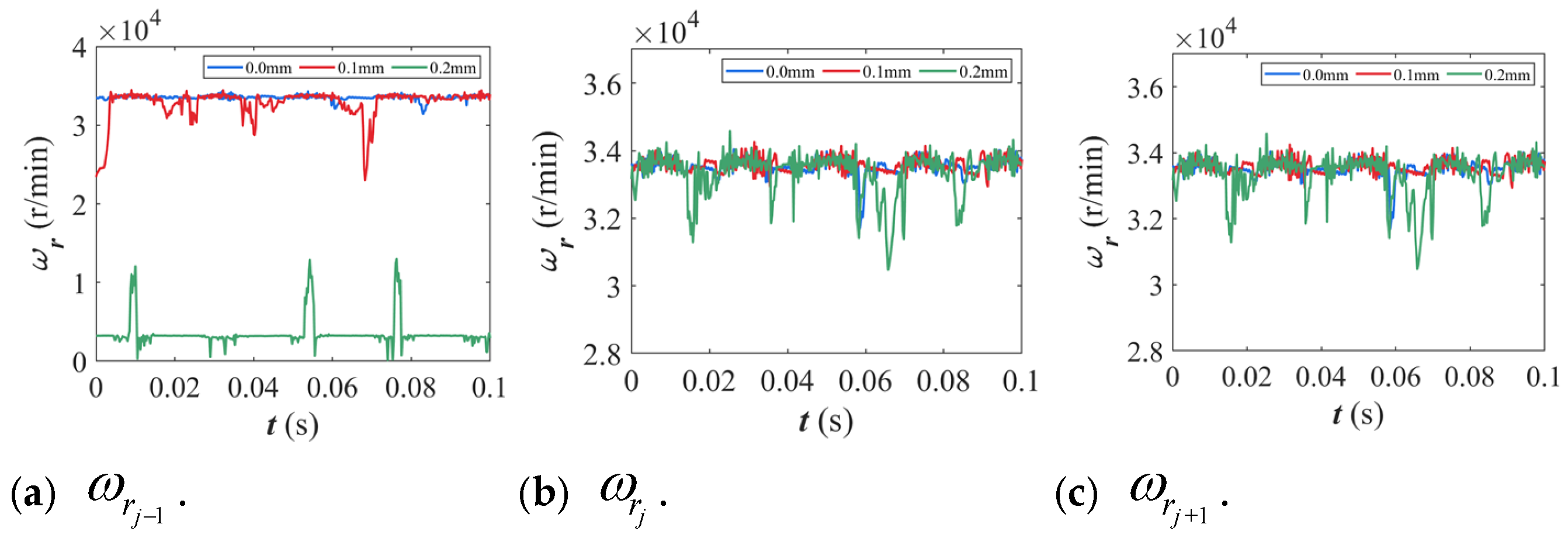
Figure 13 illustrates the rotational speeds of the rollers under varying cage pocket crossbeam deformation conditions; the extent of crossbeam deformation markedly influences the rotational speed of the rollers. When the deformation of the cage crossbeam is δ q = 0.1   mm , the rotational speed of the rollers remains essentially stable. However, with the deformation increased to δ q = 0.2   mm , the circumferential clearance of roller r j 1 is compressed, resulting in a substantial reduction in its rotational speed and a higher frequency of speed fluctuations. In contrast, for rollers r j and r j + 1 , the cage structures are normal, which largely maintain relatively constant and stable rotational speeds.
Figure 13. Rotational speeds of adjacent rollers with different levels of cage crossbeam deformation.
When cage pocket crossbeam deformation faults occur, the resulting variations in cage pocket clearance increase the traction interaction force between the cage and the rollers. If the driving force transmitted from the inner ring is insufficient to overcome this resistance, the rotational speed of the rollers falls below the theoretical value, resulting in roller slip.
Cage pocket crossbeam deformation plays a decisive role in governing pocket clearance and roller slip characteristics. Roller slips ratios exhibit notable variations under different levels of crossbeam deformation. The roller slip ratio is presented in Table 2. Initially, as deformation increases, the consequent decrease in cage pocket clearance results in a lower roller slip ratio; however, with further deformation, the slip ratio rises sharply. In contrast, rollers r j and r j + 1 , which remain unaffected by inward deformation, consistently exhibit stable slip ratios, demonstrating that local crossbeam deformation primarily influences the rollers within the deformed pocket while exerting only a minor effect on adjacent rollers.
Table 2. Roller slip rate.

3.2. Influence of Cage Pocket Side Beam Deformation on the Dynamic Characteristics of Bearings

To further investigate the effect of cage pocket side beam deformation on the dynamic behavior of the cylindrical roller bearing, the side beam at the roller–contact end of roller r j was selected for analysis. The deformation levels of the cage crossbeam, denoted as δ p = 0.0   mm , δ p = + 0.3   mm , and δ p = 0.3   mm , were selected for dynamic analysis, providing a closer representation of the actual beam deformations. The speed of the bearing inner ring was set to 6000 r/min, and a radial load of 1000 N was applied.
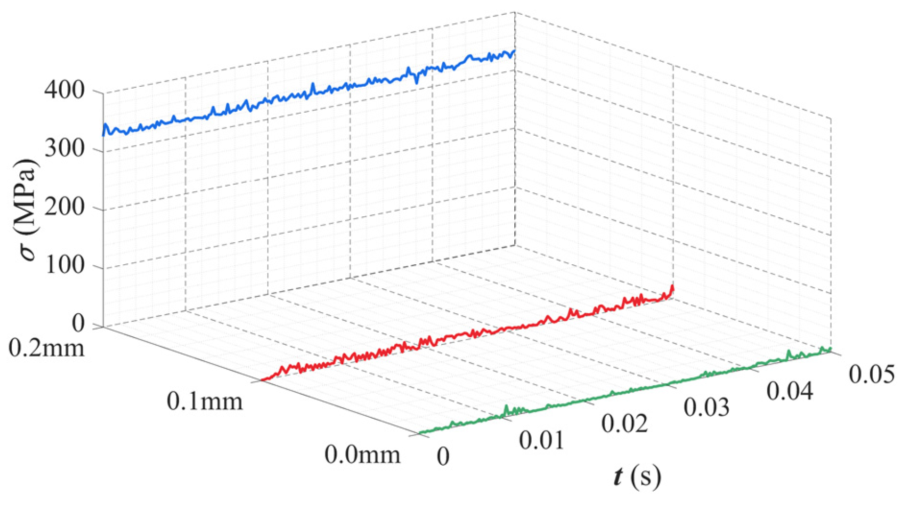
As the deformation of the cage pocket side beam reaches δ p = + 0.3   mm , its influence on roller root stress is limited, with only minor fluctuations in equivalent stress amplitudes. However, once the deformation reaches δ p = 0.3   mm , the resulting changes in local structural stiffness markedly intensify stress concentrations, leading to a pronounced increase in roller root stress, as shown in Figure 14. These results indicate that the pocket-shaped structure of the cage exerts a significant influence on stress distribution within the rollers; this underscores its critical role in both structural design and fatigue assessment.
Figure 14. Equivalent stress curve of the cage under side beam deformation.
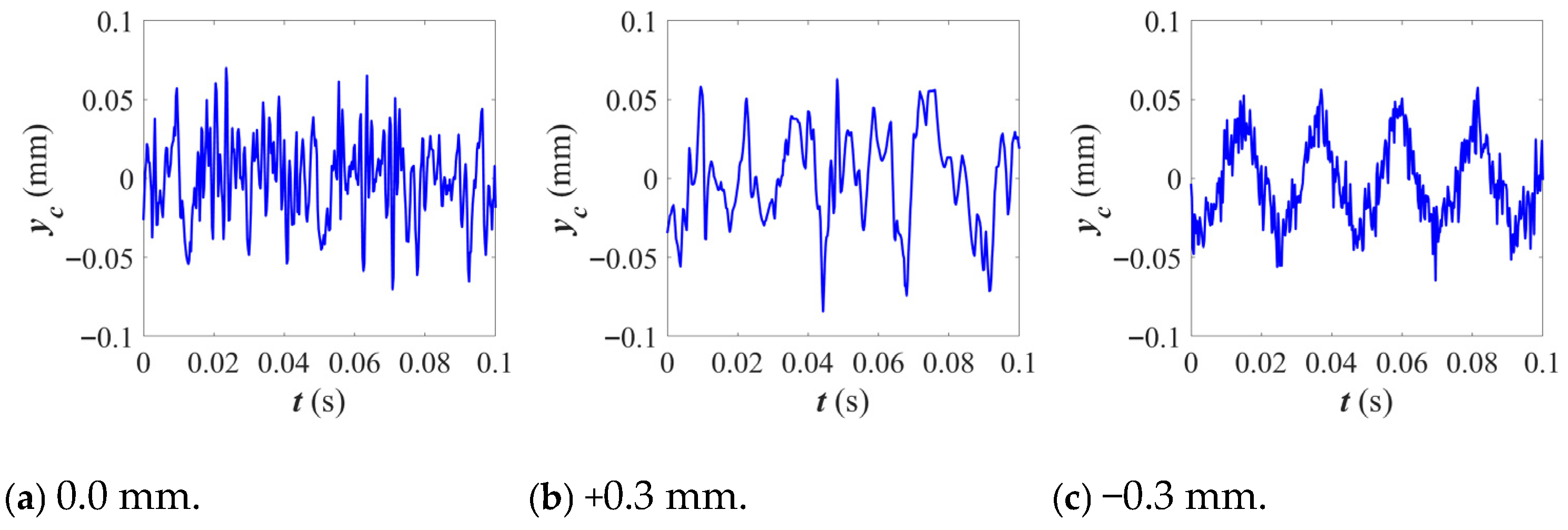
Figure 15 illustrates the radial displacement of the cage under varying pocket side beam deformation conditions. The results indicate that increasing side beam deformation alters the cage’s radial displacement behavior: as the deformation of the cage pocket side beam reaches +0.3 mm, the cage radial displacement exhibits only minor variations in vibration amplitude, indicating that positive alterations in the cage have a negligible impact. The cage, when the crossbeam deformation reaches −0.3 mm, exhibits sinusoidal radial displacement at the characteristic frequency. This results from the elimination of axial clearance in the pocket groove, which restricts roller motion and sustains vibration.
Figure 15. Radial displacement of the cage centroid under side beam deformation.
Figure 16 shows that, although deformations of the cage pocket side beam at δ p = + 0.3   mm and δ p = 0.3   mm both alter the motion trajectory of the cage center of mass, at δ p = + 0.3   mm the trajectory became increasingly chaotic with an enlarged whirl radius, indicating that the cage’s motion is progressively destabilizing. With the cage pocket side beam deformed by δ p = 0.3   mm , the motion trajectory of the cage centroid exhibits a pronounced whirl pattern; this highlights a transition from irregular disturbances to a more regular whirl behavior and reflects the evolving trend of the system’s dynamic response.
Figure 16. Trajectory of the cage centroid with side beam deformation.
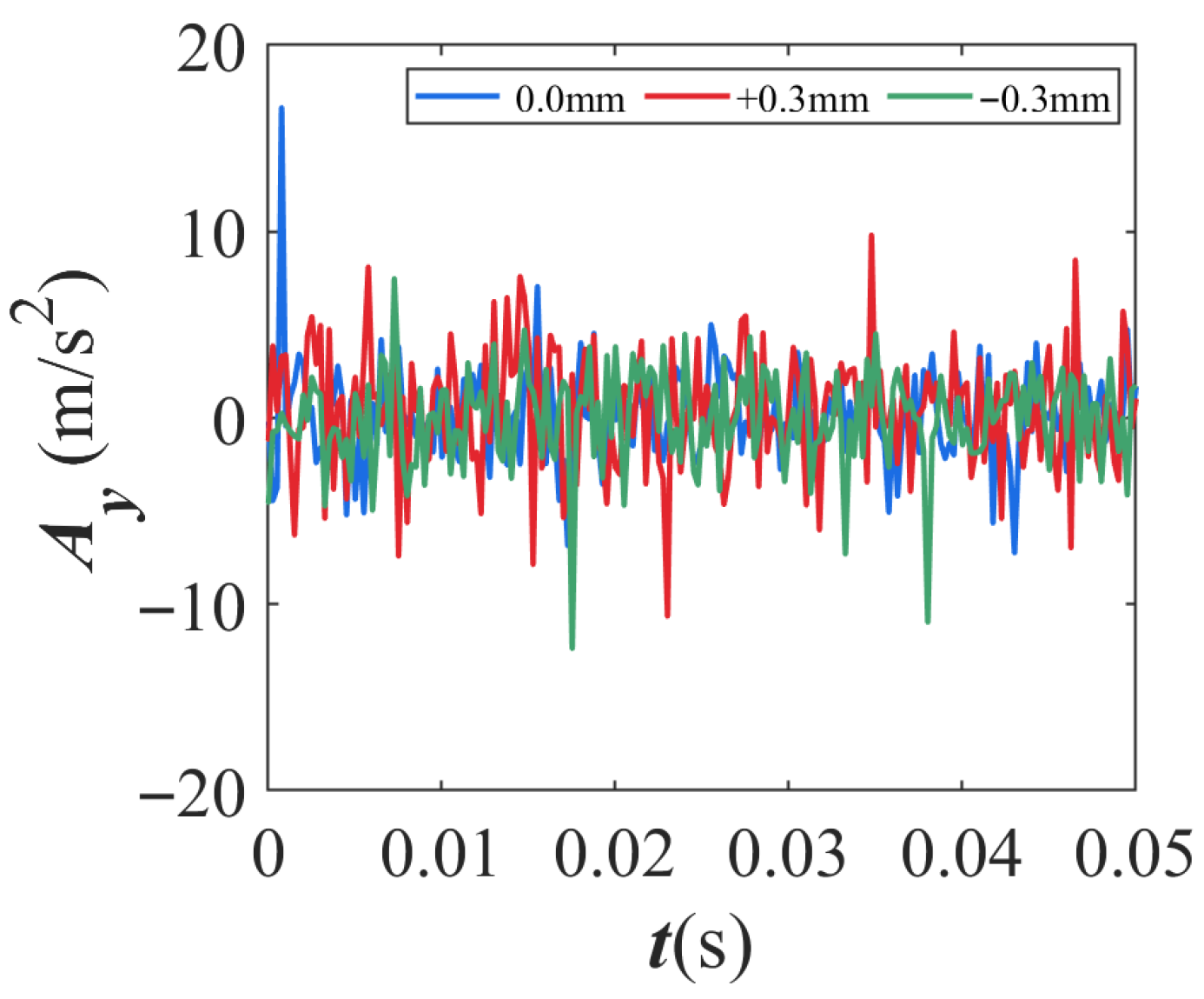
Figure 17 presents the vibration acceleration of the outer ring. When the cage is undeformed, the vibration amplitude stays within a stable range. Cage pocket side beam deformation induces sudden and irregular spikes in vibration amplitude, indicating that local cage deformation disrupts the stability of outer ring vibrations.
Figure 17. Vibration acceleration of the bearing outer ring under deformation of the cage side beams.
The rotational speeds of the cage under different cage pocket crossbeam deformation conditions are presented in Figure 18. The results indicate that side beam deformation influences cage rotational speed. The results indicate that when the deformation is δ p = + 0.3   mm , the fluctuation range of the rotational speed decreases, approaching a stable state. However, as the deformation extends to δ p = 0.3   mm , the fluctuation range increases, accompanied by a higher vibration frequency.
Figure 18. Rotational speed of the cage with side beam deformation.
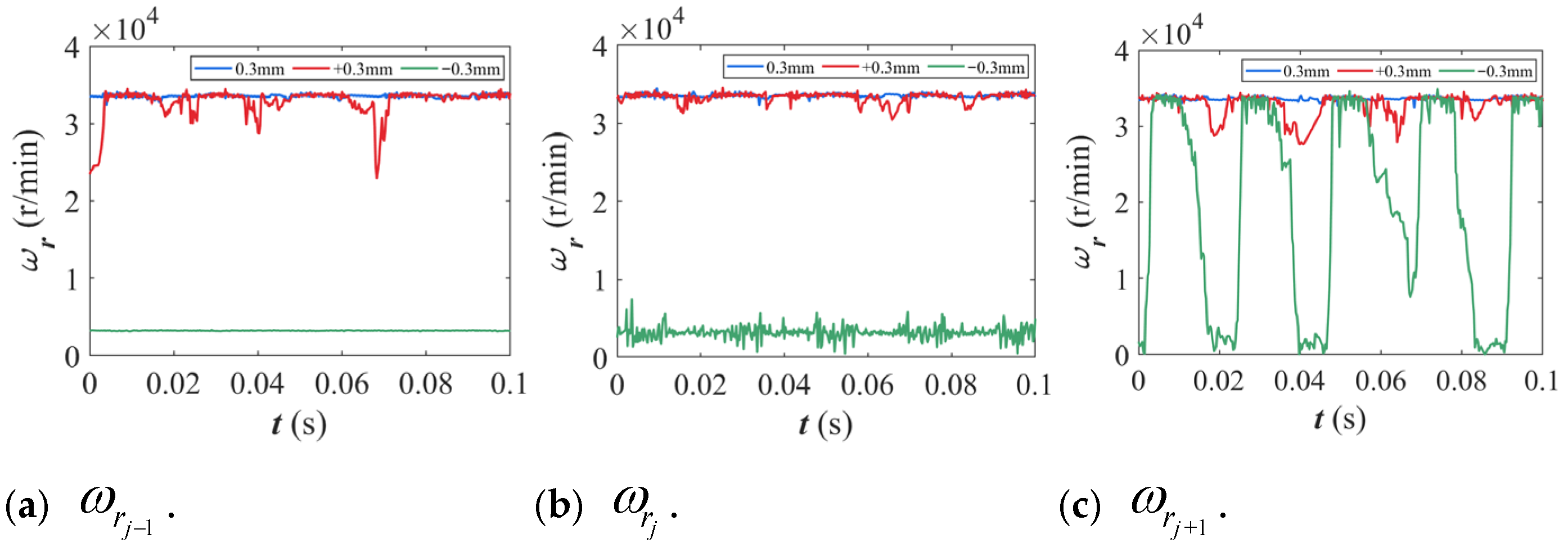
Figure 19 illustrates the rotational speeds of the rollers under varying cage pocket crossbeam deformation conditions, which indicates that the extent of side beam deformation affects roller speeds. When the deformation of the cage crossbeam is δ p = + 0.3   mm , the rotational speed of the rollers remains essentially stable. However, with the deformation increased to δ p = 0.3   mm , a significant decrease in rotational speed is observed, which highlights the sensitivity of the cage-side beams’ local deformation to the roller’s rotational velocity.
Figure 19. Rotational speeds of adjacent rollers with different levels of cage side beam deformation.
Cage pocket side beam deformation plays a decisive role in governing pocket clearance and roller slip behavior. As summarized in Table 3, it was found to affect both cage pocket clearance and roller slip ratios. Reduced contact between the roller and cage due to cage pocket side beam deformation caused a slight decrease in slip ratios. However, a pronounced increase in the slip ratio of the roller was observed once the clearance became negative. Although the rollers r j and r j + 1 were not deformed, their slip ratios changed noticeably. This indicates that the effects of side beam deformation can propagate to adjacent rollers.
Table 3. Roller slips rates.
Deformation of the cage side beam significantly affects roller clearance, slip ratios, root stress, and the dynamic behavior of adjacent rollers. This leads to destabilization of roller motion and negatively impacts the bearing’s overall dynamic performance.

4. Conclusions

The influence of local deformation in the cage pockets on the bearing’s dynamic behavior was investigated, revealing the impact of deformations in both the crossbeam and side beam of the cage pockets on bearing motion. This study’s findings are as follows:
(1)
The deviation in cage length exerts a significant influence on the dynamic performance of the bearing. Negative deviation reduces the amplitude of equivalent stress on the cage, indicating stricter constraints on its motion. As the deformation increases, the cage’s motion range diminishes while the inner ring and rollers’ rotational speed fluctuates intensifies. Negative deviations make the bearing’s overall dynamic response more sensitive; this is mainly due to the reduced clearance between the cage and rollers, which enhances friction and contact forces. The resulting restriction on cage motion causes a rotational speed imbalance, leading to greater fluctuations.
(2)
The deformation of the cage pocket crossbeam exhibits distinct influence patterns. Negative deformation of the side beam significantly increases the root stress of the cage, which stabilizes at approximately 320.51 MPa. Meanwhile, the cage centroid’s motion transitions from irregular oscillations to sinusoidal fluctuations at characteristic frequencies, accompanied by a reduction in whirl amplitude. When the side beam undergoes positive deformation, the clearance between the cage and rollers increases, which weakens their interactions. As a result, the variation in root stress becomes negligible, and the system’s dynamic stability improves. However, positive deformation of the side beam also induces irregular, large-amplitude fluctuations in the outer ring’s vibration response, indicating that local cage deformation can compromise the stability of outer ring vibrations.
(3)
Negative deviation significantly affects the performance of cylindrical roller bearings by reducing the clearance between the rolling elements and the cage. This leads to increased contact, which in turn amplifies friction and impact forces among the components, especially with side beam deviation. Negative deviation increases stress, restricts mobility, and alters interaction characteristics, severely disrupting the bearing’s equilibrium and resulting in pronounced fluctuations in speed and motion. In contrast, positive deviation enlarges clearance, facilitating smoother interactions, reducing stress, and enhancing the system’s overall stability.
(4)
In the practical design and assembly of bearings, the influence of negative deviation should be minimized because the location and direction of local cage deformation directly affect roller clearance and the slip ratio. As deformation increases, the load conditions of the rollers change, restricting their normal motion. Furthermore, roller motion in both deformed and undeformed regions is affected, thereby inducing a cascading effect in roller slip. Ultimately, this dynamic interference severely deteriorates bearing performance and shortens its service life.
(5)
The influence of local cage deformation defects on the dynamic characteristics of cylindrical roller bearings was analyzed. The insights gained from this study provide valuable guidance for improving the design and manufacturing processes of cylindrical roller bearings, thereby ensuring their greater reliability and durability. Future research may explore the effects of multiple coupled faults, such as the interaction between local cage deformation, surface damage, and assembly deviations, on the bearing system.

Author Contributions

Conceptualization and investigation by B.W.; writing—original draft by S.L.; simulation and data curation by X.Q.; writing—review and editing by M.W.; writing—modification by Z.-G.Z. and J.Z. All authors have read and agreed to the published version of the manuscript.

Funding

This research was funded by the Scientific research project of the Education Department of Liaoning Province, grant number LJ212510152005; The General Project of the Liaoning Provincial Department of Education, No. LJKMZ20220864 and No. JYTMS20230440; the Liaoning Province Science and Technology Development Project, grant number 2024JH6-10020004; and the Dalian City Major Science and Technology Foundation, grant numbers 2024JB11PT004 and 2023YF12GX016.

Data Availability Statement

The original contributions presented in the study are included in the article; further inquiries can be directed at the corresponding author.

Conflicts of Interest

The authors declare no conflicts of interest.

References

  1. Ghaisas, N.; Wassgren, C.R.; Sadeghi, F. Cage Instabilities in Cylindrical Roller Bearings. Journal of Tribology. J. Tribol. 2004, 126, 681–689. [Google Scholar] [CrossRef]
  2. Kumbhar, S.G.; Sudhagar P, E.; Desavale, R.G. An overview of dynamic modeling of rolling-element bearings. Noise Vib. Worldw. 2021, 52, 3–18. [Google Scholar] [CrossRef]
  3. Guo, Z.; Ju, H.; Wang, K. A Novel Explicit Canonical Dynamic Modeling Method for Multi-Rigid-Body Mechanisms Considering Joint Friction. Aerospace 2024, 11, 368. [Google Scholar] [CrossRef]
  4. Pesterev, D.; Druzhina, O.; Pchelintsev, A.; Nepomuceno, E.; Butusov, D. Numerical integration schemes based on composition of adjoint multistep methods. Algorithms 2022, 15, 463. [Google Scholar] [CrossRef]
  5. Xin, J.; Wang, Z.; Hao, X.; Qi, X.; Wang, Y.; Wen, B. Dynamic Characteristics Analysis of Cylindrical Roller Bearing with Dimensional Deviations in Cage Pocket. Appl. Sci. 2024, 14, 9433. [Google Scholar] [CrossRef]
  6. Zhang, L.; Xiang, Z.; Zhang, H.; Liu, W.; Huang, C.; Qian, T.; Wang, C.; Liu, J. An Investigation of the Effect of the Fault Degree on the Dynamic Characteristics and Crack Propagation of Rolling Bearings. Appl. Sci. 2025, 15, 1198. [Google Scholar] [CrossRef]
  7. Yang, Y.; Qi, X.; Wang, Y.; Wang, M.; Wen, B.; Zhai, J. Dynamic Characteristics of a Cylindrical Roller Bearing with Cage Cracks. Lubricants 2025, 13, 25. [Google Scholar] [CrossRef]
  8. Chen, Q.; Jiang, S.; Duan, D. Fracture Analysis and Working Stress Calculation of Bearing Cage Used in Charging Pump in a Nuclear Power Plant. Metals 2023, 13, 1380. [Google Scholar] [CrossRef]
  9. Li, H.; Liu, H.; Liu, Y.; Qi, S.; Wang, F. On the dynamic characteristics of ball bearing with cage broken. Lubr. Tribol. 2020, 72, 881–886. [Google Scholar] [CrossRef]
  10. Wen, B.; Ren, H.; Zhang, H.; Han, Q. Experimental investigation of cage motions in an angular contact ball bearing. Part J J. Eng. Tribol. 2017, 231, 1041–1055. [Google Scholar] [CrossRef]
  11. Chen, H.; Zhang, H.; Liang, H.; Wang, W. The collision and cage stability of cylindrical roller bearing considering cage flexibility. Tribol. Int. 2024, 192, 109219. [Google Scholar] [CrossRef]
  12. Dai, P.; Liang, X.; Lin, X.; Wang, F.; Wang, J. Investigation on stability and slip characteristic of the cage in cylindrical roller bearing with localized failure on raceways. Mech. Syst. Signal Process. 2023, 199, 110469. [Google Scholar] [CrossRef]
  13. Fan, L.; Zhao, X.; Hao, W.; Miao, C.; Hu, X.; Fang, C. Tribo-Dynamic Behavior of Double-Row Cylindrical Roller Bearings Under Raceway Defects and Cage Fracture. Lubricants 2025, 13, 80. [Google Scholar] [CrossRef]
  14. Zarei, A.; Farahani, S.; Pradeep, S.A.; Driscoll, J.; Lukasiewicz, R.; Pilla, S. Design and manufacturing of roller bearing polymeric cages and development of a theoretical model for predicting the roller push-out force. Sci. Rep. 2022, 12, 1017. [Google Scholar] [CrossRef]
  15. Pederson, B.M.; Sadeghi, F.; Wassgren, C. The effects of cage flexibility on ball-to-cage pocket contact forces and cage instability in deep groove ball bearings. SAE Trans. 2006, 115, 260–271. [Google Scholar]
  16. Weinzapfel, N.; Sadeghi, F. A discrete element approach for modeling cage flexibility in ball bearing dynamics simulations. J. Tribol. 2009, 131, 021101. [Google Scholar] [CrossRef]
  17. Ma, S.; Tian, C.; Yang, C.; Yan, K.; Stefano, L.; Hong, J. New bearing model with flexible cage and study of dynamic behavior under variable-speed. Mech. Syst. Signal Process. 2024, 208, 111045. [Google Scholar] [CrossRef]
  18. Liu, Y.; Chen, Z.; Tang, L.; Zhai, W. Skidding dynamic performance of rolling bearing with cage flexibility under accelerating conditions. Mech. Syst. Signal Process. 2021, 150, 107257. [Google Scholar] [CrossRef]
  19. Wang, M.; Yan, K.; Tang, Q.; Guo, J.; Zhu, Y.; Hong, J. Dynamic modeling and properties analysis for ball bearing driven by structure flexible deformations. Tribol. Int. 2023, 179, 108163. [Google Scholar] [CrossRef]
  20. Neglia, S.G.; Culla, A.; Fregolent, A. Bearing Cage Dynamics: Cage Failure and Bearing Life Estimation. In Nonlinear Dynamics, Volume 1: Proceedings of the 33rd IMAC, A Conference and Exposition on Structural Dynamics; Springer: Cham, Switzerland, 2016. [Google Scholar]
  21. Guo, Y.; Parker, R. Rolling Element Bearing Stiffness Matrix Determination (Presentation); National Renewable Energy Lab. (NREL): Golden, CO, USA, 2014. [Google Scholar]
  22. Qin, Y.; Li, C.; Wu, X.; Wang, Y.; Chen, H. Multiple-degree-of-freedom dynamic model of rolling bearing with a localized surface defect. Mech. Mach. Theory 2020, 154, 104047. [Google Scholar] [CrossRef]
  23. Wang, P.; Yang, Y.; Ma, H.; Xu, H.; Li, X.; Luo, Z.; Wen, B. Vibration characteristics of rotor-bearing system with angular misalignment and cage fracture: Simulation and experiment. Mech. Syst. Signal Process. 2023, 182, 109545. [Google Scholar] [CrossRef]
Disclaimer/Publisher’s Note: The statements, opinions and data contained in all publications are solely those of the individual author(s) and contributor(s) and not of MDPI and/or the editor(s). MDPI and/or the editor(s) disclaim responsibility for any injury to people or property resulting from any ideas, methods, instructions or products referred to in the content.

Article Metrics

Citations

Article Access Statistics

Article metric data becomes available approximately 24 hours after publication online.