

Three-Dimensional Enlow’s Counterpart Analysis: Neutral Track

 ,
,  and
and 
Abstract
1. Introduction
2. Materials and Methods
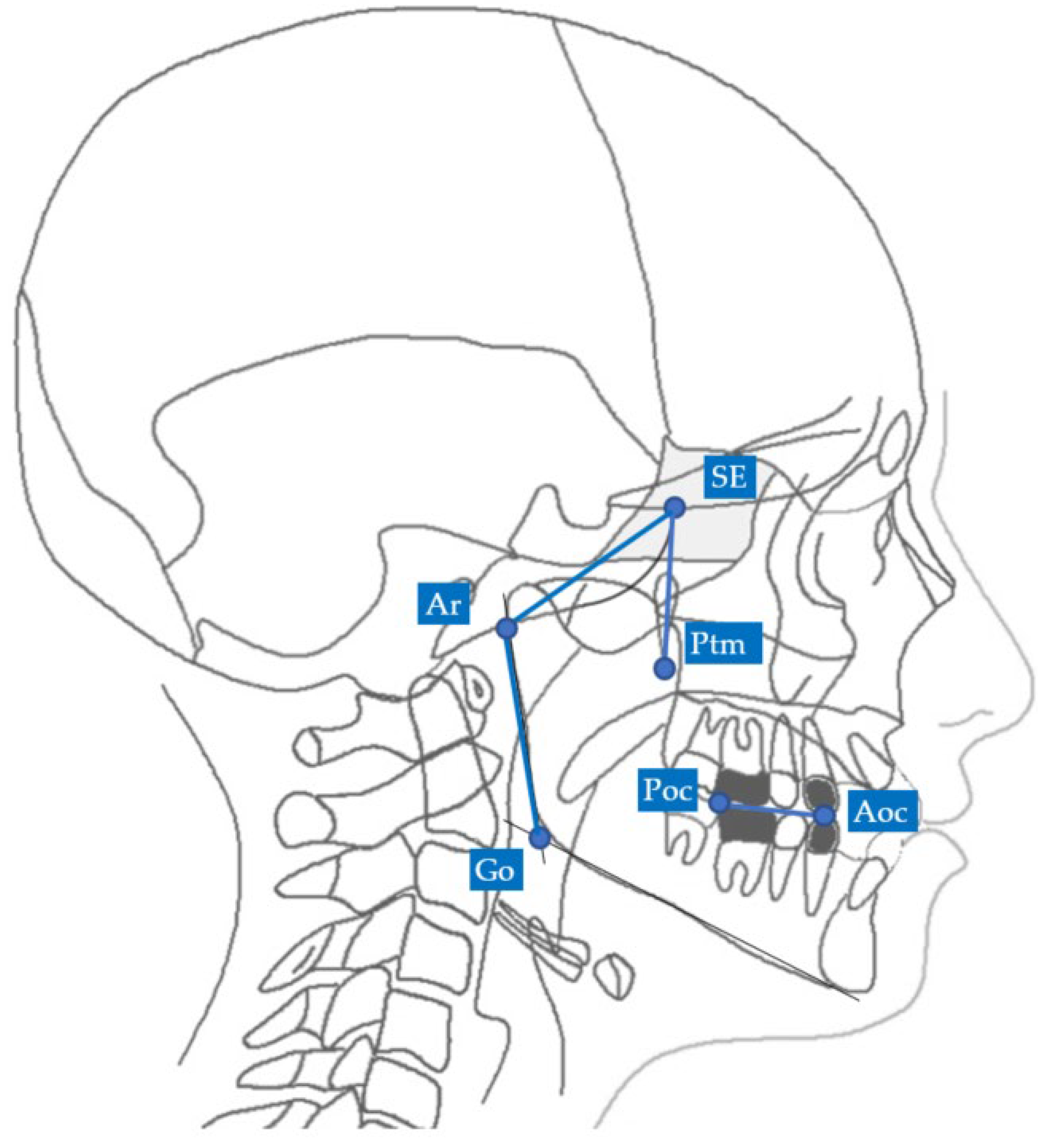
2.1. Two-Dimensional Neutral Track Analysis
2.1.1. Two-Dimensional Individual Track
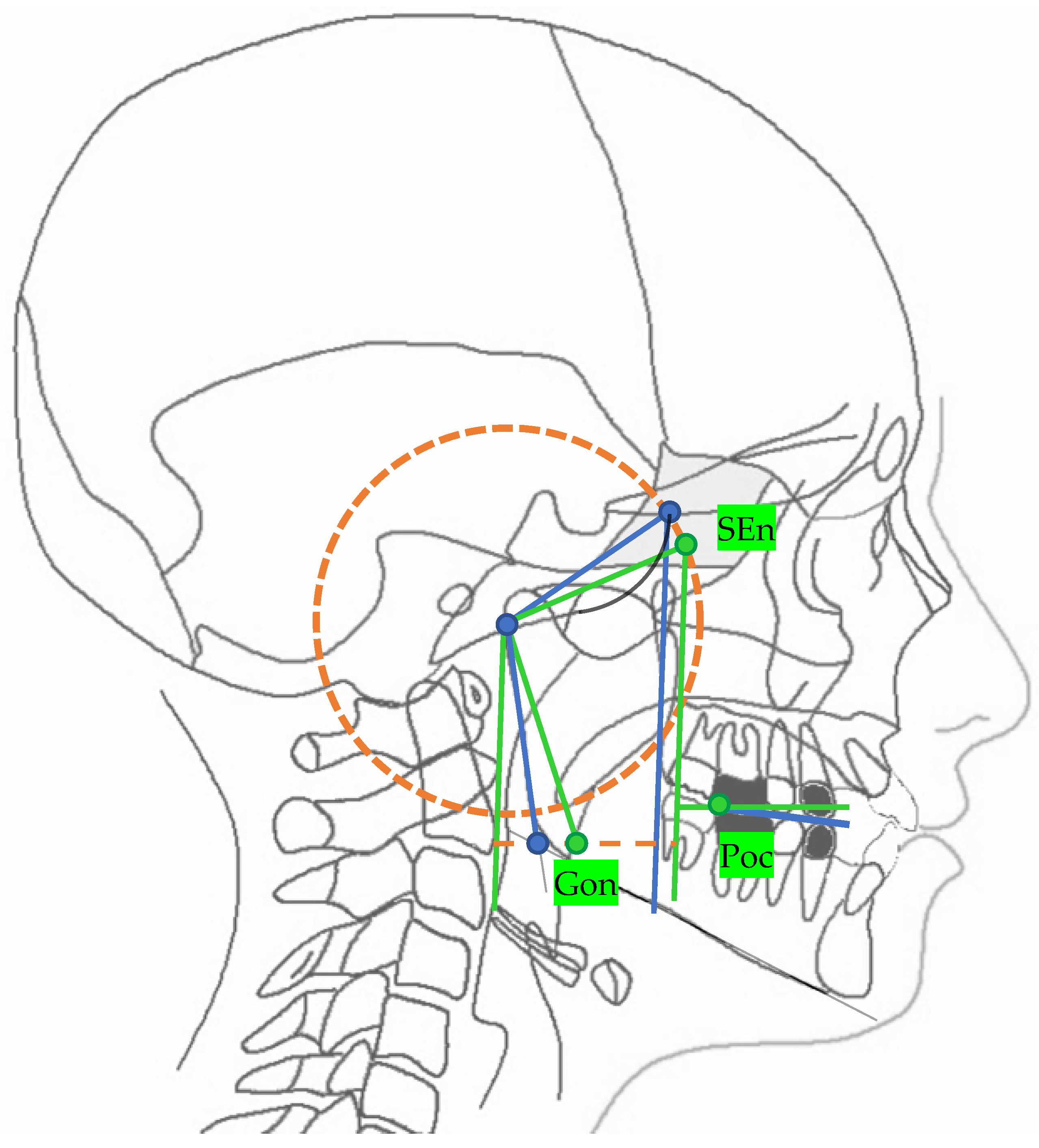
2.1.2. Two-Dimensional Neutral Track
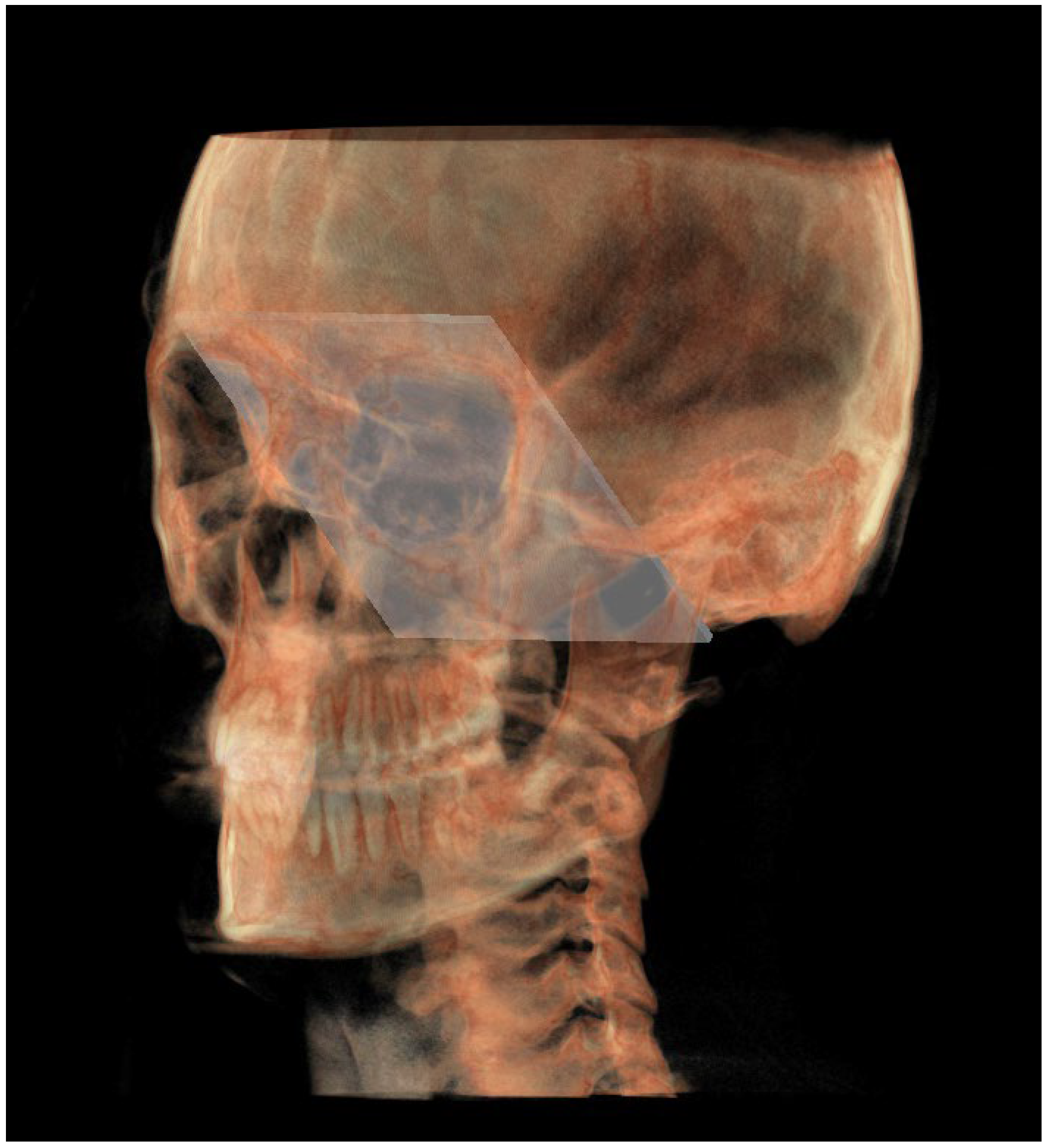
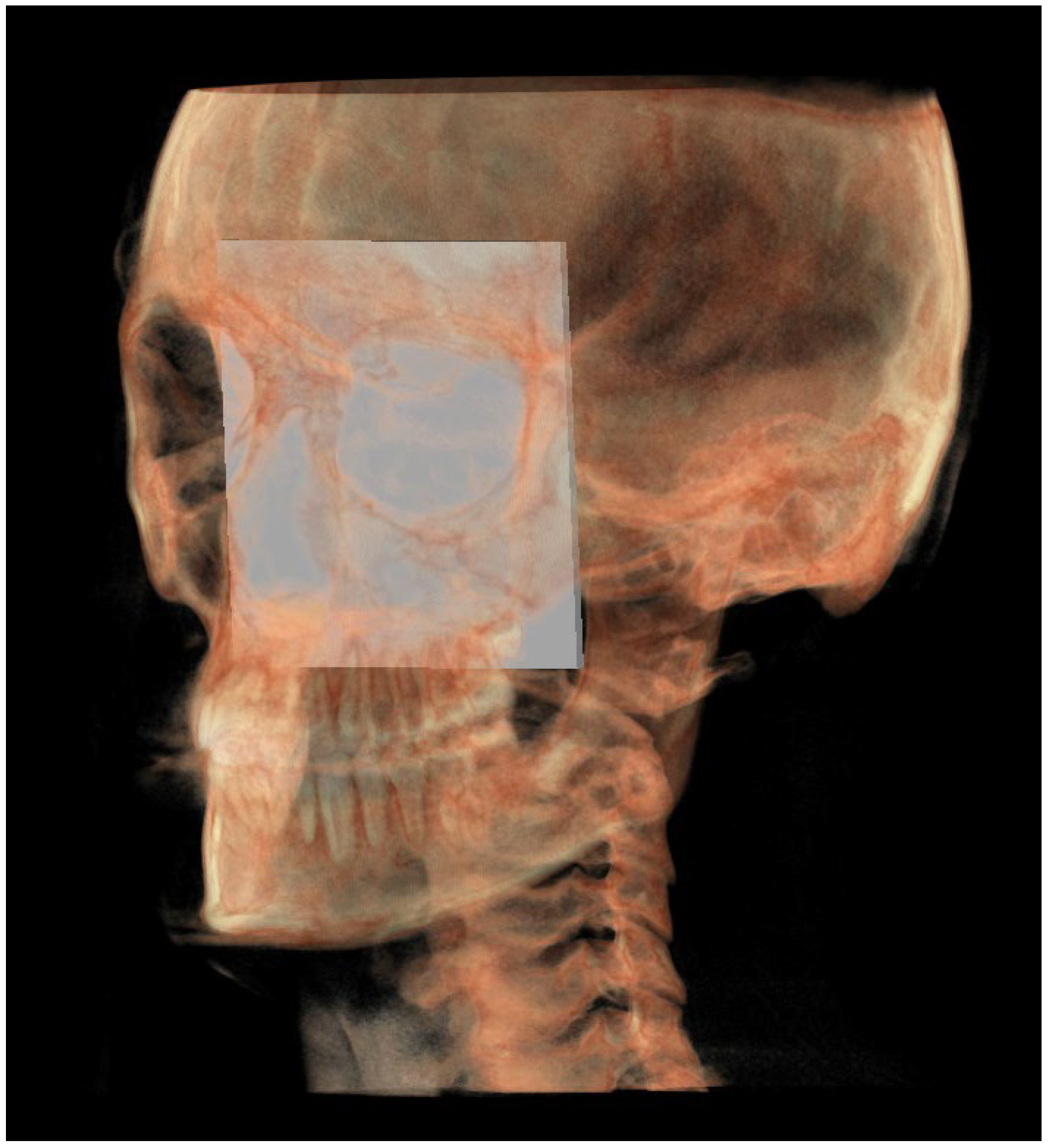
2.2. Three-Dimensionla Neutral Track Analysis
2.2.1. Three-Dimensional Individual Track
- ○
- ○
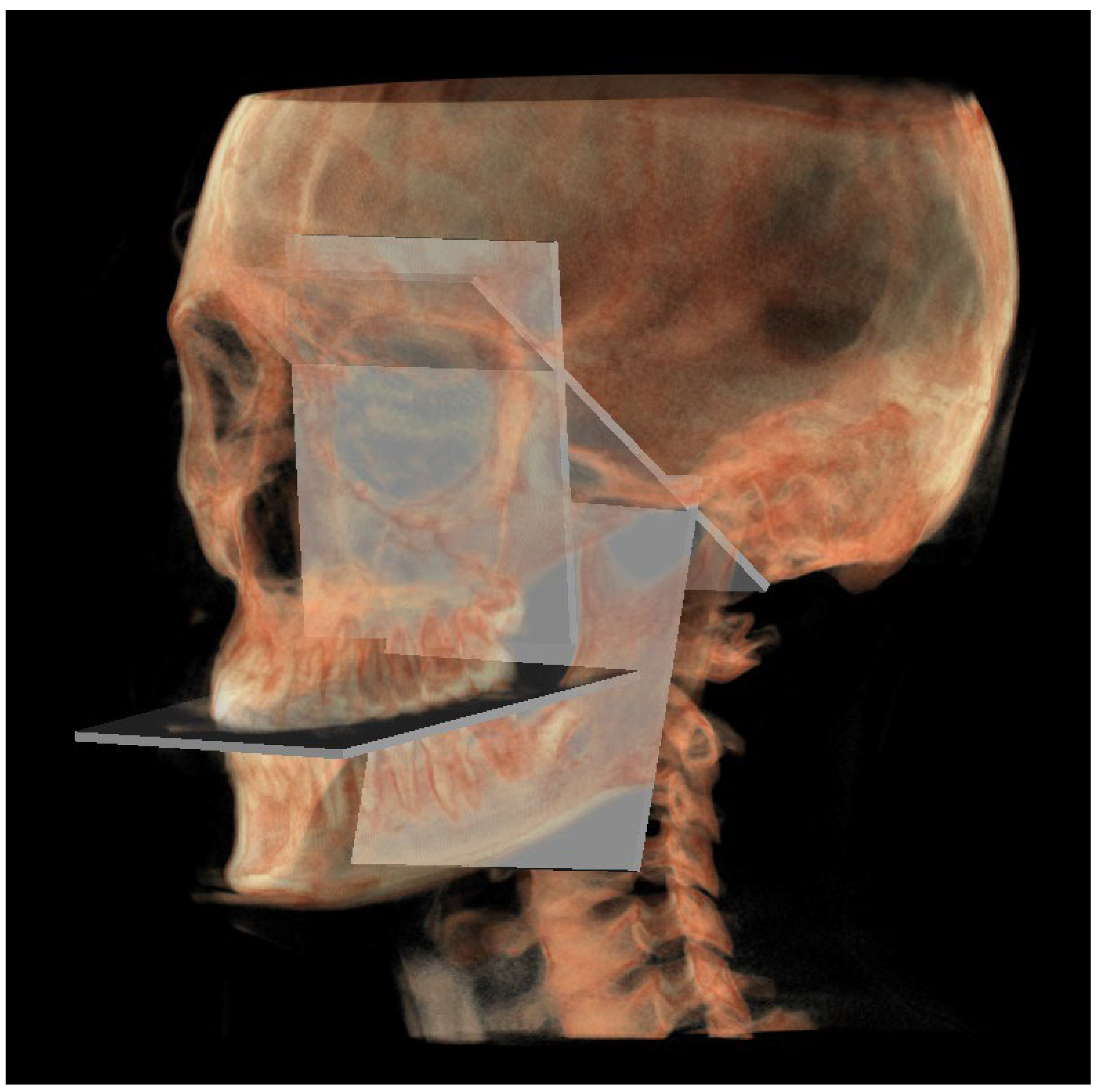
- PM (Figure 4) was identified by the points lMCF, rMCF and posterior nasal spine (PNS);
- ○
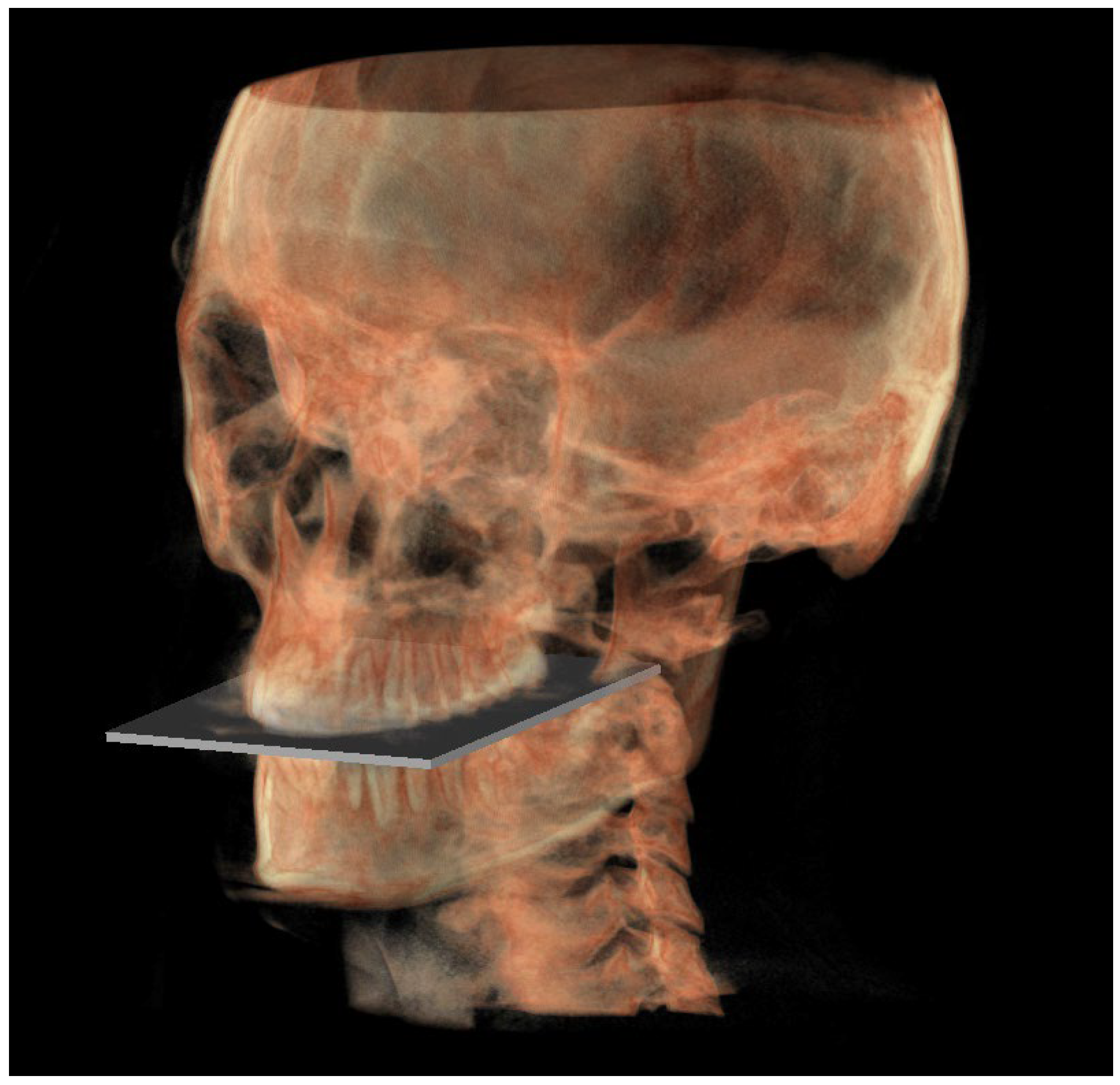
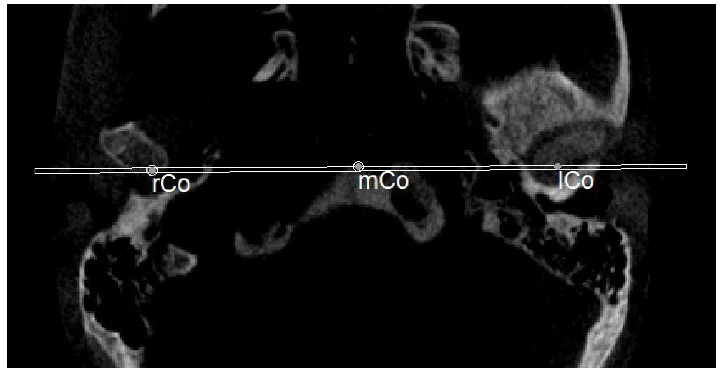
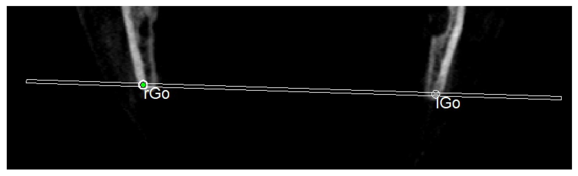
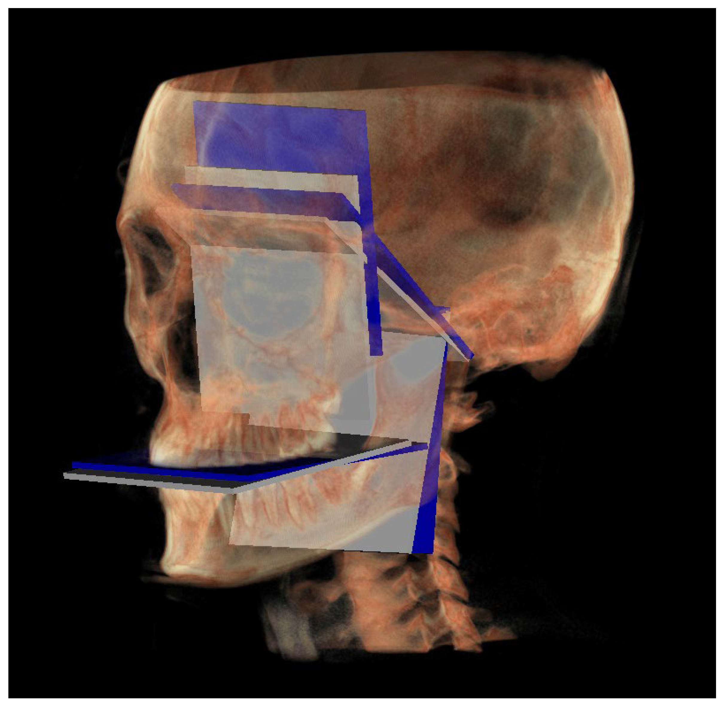
- The mandibular ramus plane (MR) (Figure 5) was identified by the following points: the middle points between the right and left condylion (mCo) and the right Gonion (rGo) and left Gonion (lGo). To adequately locate the mCo, it is advisable to draw a line on the frontal view from the right condylion to the left one to have a reference along which measure the mid-distance;
- ○
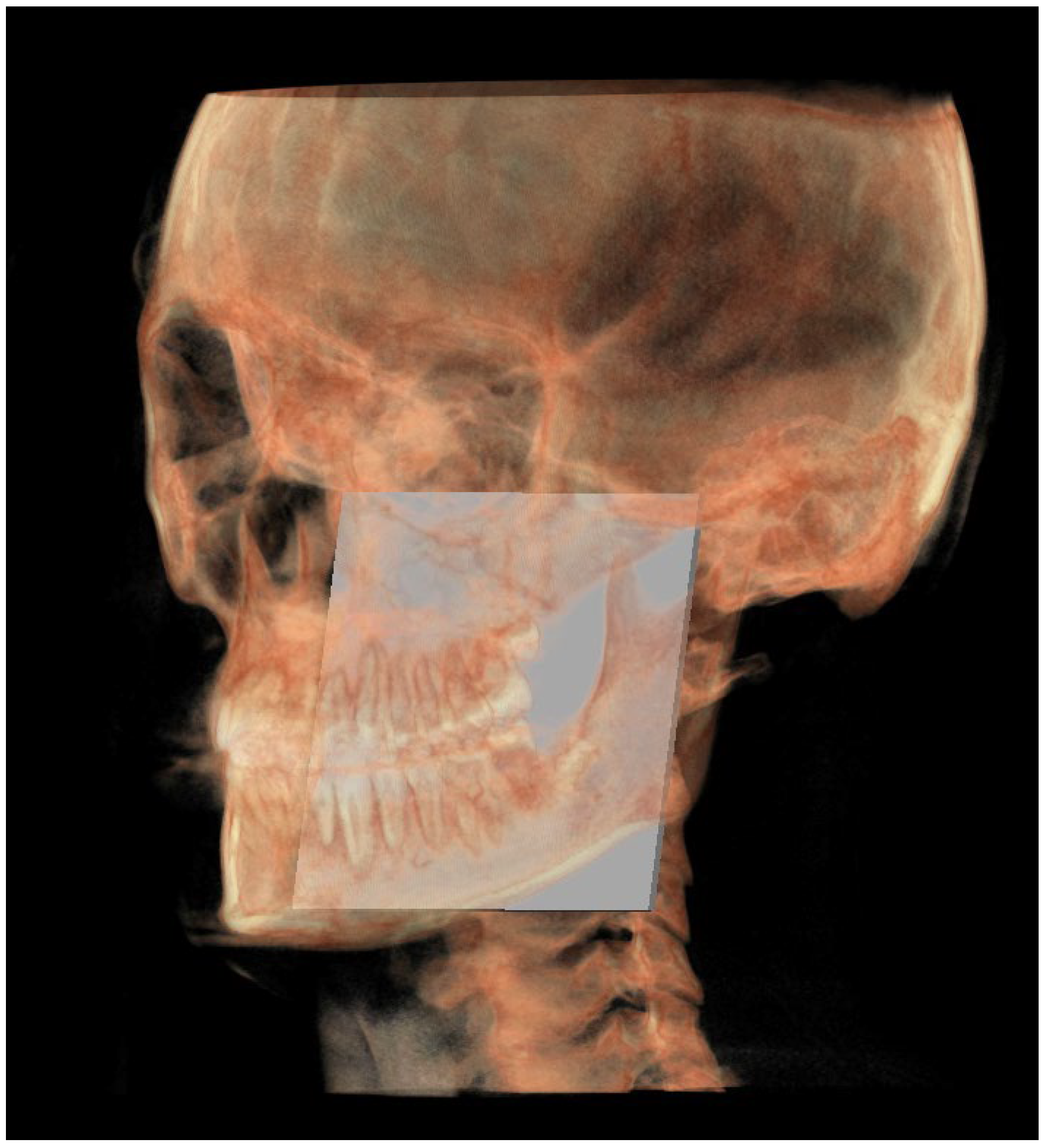
- The functional occlusal plane (FOP) (Figure 6) was identified by the posterior occlusal contact right side (rPoc), posterior occlusal contact left side (lPoc) and the middle point between the right and left anterior occlusal contact (mAoc). To adequately locate the mAoc, it is advisable to draw a line on the transversal view from the right mesial premolar contact to the left one to have a reference along which measure the distance.
2.2.2. Three-Dimensional Neutral Track
2.3. Statistical Analysis
3. Results
4. Discussion
5. Conclusions
- -
- Orthodontists in the diagnostic phase when there is the need to assess at which level the malocclusion is located;
- -
- Orthognathic surgery planning.
Author Contributions
Funding
Institutional Review Board Statement
Informed Consent Statement
Data Availability Statement
Conflicts of Interest
References
- Pinheiro, M.; Ma, X.; Fagan, M.J.; Grant, T.M.; Ping, L.; Gautham, S.; Peter, A.M. A 3D cephalometric protocol for the accurate quantification of the craniofacial symmetry and facial growth. J. Biol. Eng. 2019, 17, 13–42. [Google Scholar] [CrossRef]
- Gateno, J.; Xia, J.J.; Teichgraeber, J.F. New 3-dimensional cephalometric analysis for orthognathic surgery. J. Oral Maxillofac. Surg. 2011, 69, 606–622. [Google Scholar] [CrossRef] [PubMed]
- Park, S.H.; Yu, H.S.; Kim, K.D.; Lee, K.J.; Baik, H.S. A proposal for a new analysis of craniofacial morphology by 3-dimensional computed tomography. Am. J. Orthod. Dentofac. Orthop. 2006, 129, 600.e23–600.e34. [Google Scholar] [CrossRef] [PubMed]
- Gaur, A.; Dhillon, M.; Puri, N.; Ahuja, U.S.; Rathore, A. Questionable accuracy of CBCT in determining bone density: A comparative CBCT-CT in vitro study. Dent. Med. Probl. 2022, 59, 413–419. [Google Scholar] [CrossRef]
- Swennen, G.R.; Schutyser, F. Three-dimensional cephalometry: Spiral multi-slice vs. cone-beam computed tomography. Am. J. Orthod. Dentofac. Orthop. 2006, 130, 410–416. [Google Scholar] [CrossRef] [PubMed]
- Smektała, T.; Jędrzejewski, M.; Szyndel, J.; Sporniak-Tutak, K.; Olszewski, R. Experimental and clinical assessment of three-dimensional cephalometry: A systematic review. J. Cranio-Maxillofac. Surg. 2014, 42, 1795–1801. [Google Scholar] [CrossRef] [PubMed]
- Pittayapat, P.; Limchaichana-Bolstad, N.; Willems, G.; Jacobs, R. Three-dimensional cephalometric analysis in orthodontics: A systematic review. Orthod. Craniofac. Res. 2014, 17, 69–91. [Google Scholar] [CrossRef]
- D’Attilio, M.; Peluso, A.; Falone, G.; Pipitone, R.; Moscagiuri, F.; Caroccia, F. “3D Counterpart Analysis”: A Novel Method for Enlow’s Counterpart Analysis on CBCT. Diagnostics 2022, 12, 2513. [Google Scholar] [CrossRef]
- Enlow, D.H.; Hans, M.G. Essential of Facial Growth, 1st ed.; Saunders: Philadelphia, PA, USA, 1996. [Google Scholar]
- Enlow, D.H.; Kuroda, T.; Lewis, A.B. The morphogenetic basis for craniofacial form and pattern. Angle Orthod. 1971, 41, 161–188. [Google Scholar]
- Moscagiuri, F.; Caroccia, F.; Lopes, C.; Di Carlo, B.; Di Maria, E.; Festa, F.; D’Attilio, M. Evaluation of Articular Eminence Inclination in Normo-Divergent Subjects with Different Skeletal Classes through CBCT. Int. J. Environ. Res. Public Health 2021, 18, 5992. [Google Scholar] [CrossRef]
- Cevidanes, L.H.S.; Franco, A.A.; Gerig, G.; Proffit, W.R.; Slice, D.E.; Enlow, D.H.; Yamashita, H.K.; Kim, Y.J.; Scanavini, M.A.; Vigorito, J.W. Assessment of mandibular growth and response to orthopedic treatment with 3-dimensional magnetic resonance images. Am. J. Orthod. Dentofac. Orthop. 2005, 128, 16–25. [Google Scholar] [CrossRef] [PubMed]
- Vidal-Manyari, P.A.; Arriola-Guillén, L.E.; Jimenez-Valdivia, L.M.; Dias-Da Silveira, H.L.; Boessio-Vizzotto, M. Effect of the application of software on the volumetric and cross-sectional assessment of the oropharyngeal airway of patients with and without an open bite: A CBCT study. Dent. Med. Probl. 2022, 59, 397–405. [Google Scholar] [CrossRef]
- Gibson, M.; Cron, R.Q.; Stoll, M.L.; Kinard, B.E.; Patterson, T.; Kau, C.H. A 3D CBCT Analysis of Airway and Cephalometric Values in Patients Diagnosed with Juvenile Idiopathic Arthritis Compared to a Control Group. Appl. Sci. 2022, 12, 4286. [Google Scholar] [CrossRef]
- Tanna, N.K.; AlMuzaini, A.A.A.Y.; Mupparapu, M. Imaging in Orthodontics. Dent. Clin. N. Am. 2021, 65, 623–641. [Google Scholar] [CrossRef]
- Bichu, Y.M.; Hansa, I.; Bichu, A.Y.; Premjani, P.; Flores-Mir, C.; Vaid, N.R. Applications of artificial intelligence and machine learning in orthodontics: A scoping review. Prog. Orthod. 2021, 22, 18. [Google Scholar] [CrossRef] [PubMed]
- Khanagar, S.B.; Al-Ehaideb, A.; Vishwanathaiah, S.; Maganur, P.C.; Patil, S.; Naik, S.; Baeshen, H.A.; Sarode, S.S. Scope and performance of artificial intelligence technology in orthodontic diagnosis, treatment planning, and clinical decision-making—A systematic review. J. Dent. Sci. 2021, 16, 482–492. [Google Scholar] [CrossRef] [PubMed]
- Mario, M.C.; Abe, J.M.; Ortega, N.R.; Del Santo, M., Jr. Paraconsistent artificial neural network as auxiliary in cephalometric diagnosis. Artif. Organs 2010, 34, E215–E221. [Google Scholar] [CrossRef]
- Yu, H.J.; Cho, S.R.; Kim, M.J.; Kim, W.H.; Kim, J.W.; Choi, J. Automated skeletal classification with lateral cephalometry based on artificial intelligence. J. Dent. Res. 2020, 99, 249–256. [Google Scholar] [CrossRef]
- Kunz, F.; Stellzig-Eisenhauer, A.; Zeman, F.; Boldt, J. Artificial intelligence in orthodontics: Evaluation of a fully automated cephalometric analysis using a customized convolutional neural network. J. Orofac. Orthop. 2020, 81, 52–68. [Google Scholar] [CrossRef]
- Nishimoto, S.; Sotsuka, Y.; Kawai, K.; Ishise, H.; Kakibuchi, M. Personal computer- based cephalometric landmark detection with deep learning, using cephalograms on the internet. J. Craniofac. Surg. 2019, 30, 91–95. [Google Scholar] [CrossRef]
- Kim, H.; Shim, E.; Park, J.; Kim, Y.J.; Lee, U.; Kim, Y. Web-based fully automated cephalometric analysis by deep learning. Comput. Methods Programs Biomed. 2020, 194, 105513. [Google Scholar] [CrossRef] [PubMed]
- Neelapu, B.C.; Kharbanda, O.P.; Sardana, V.; Gupta, A.; Vasamsetti, S.; Balachandran, R.; Sardana, H.K. Automatic localization of three-dimensional cephalometric landmarks on CBCT images by extracting symmetry features of the skull. Dentomaxillofac. Radiol. 2018, 47, 20170054. [Google Scholar] [CrossRef]
- Ma, Q.; Kobayashi, E.; Fan, B.; Nakagawa, K.; Sakuma, I.; Masamune, K.; Suenaga, H. Automatic 3D landmarking model using patch-based deep neural networks for CT image of oral and maxillofacial surgery. Int. J. Med. Robot. 2020, 16, e2093. [Google Scholar] [CrossRef] [PubMed]
- Montúfar, J.; Romero, M.; Scougall-Vilchis, R.J. Hybrid approach for automatic cephalometric landmark annotation on cone-beam computed tomography volumes. Am. J. Orthod. Dentofac. Orthop. 2018, 154, 140–150. [Google Scholar] [CrossRef]
- Gupta, A.; Kharbanda, O.P.; Sardana, V.; Balachandran, R.; Sardana, H.K. A knowledge-based algorithm for automatic detection of cephalometric landmarks on CBCT images. Int. J. Comput. Assist. Radiol. Surg. 2015, 10, 1737–1752. [Google Scholar] [CrossRef] [PubMed]
- Ed-Dhahraouy, M.; Riri, H.; Ezzahmouly, M.; Bourzgui, F.; El Moutaoukkil, A. A new methodology for automatic detection of reference points in 3D cephalometry: A pilot study. Int. Orthod. 2018, 16, 328–337. [Google Scholar] [CrossRef]
- Thurzo, A.; Strunga, M.; Havlínová, R.; Reháková, K.; Urban, R.; Surovková, J.; Kurilová, V. Smartphone-Based Facial Scanning as a Viable Tool for Facially Driven Orthodontics? Sensors 2022, 22, 7752. [Google Scholar] [CrossRef]
- Chen, H.; van Eijnatten, M.; Wolff, J.; de Lange, J.; van der Stelt, P.F.; Lobbezoo, F.; Aarab, G. Reliability and accuracy of three imaging software packages used for 3D analysis of the upper airway on cone beam computed tomography images. Dentomaxillofac. Radiol. 2017, 46, 20170043. [Google Scholar] [CrossRef]
- Dos Santos Trento, G.; Moura, L.B.; Spin-Neto, R.; Jürgens, P.C.; Aparecida Cabrini Gabrielli, M.; Pereira-Filho, V.A. Comparison of Imaging Softwares for Upper Airway Evaluation: Preliminary Study. Cranio-Maxillofac. Trauma Reconstr. 2018, 11, 273–277. [Google Scholar] [CrossRef]
- Lo Giudice, A.; Ronsivalle, V.; Gastaldi, G.; Leonardi, R. Assessment of the accuracy of imaging software for 3D rendering of the upper airway, usable in orthodontic and craniofacial clinical settings. Prog. Orthod. 2022, 23, 22. [Google Scholar] [CrossRef]


| Landmarks | |
|---|---|
| SE | Sphenoethmoidal junction: the intersection of the averaged image of the right and left shadows of the great wings of the sphenoid with the floor of the anterior cranial fossae |
| Ar | Articulare: the point of intersection between the posterior margin of the ramus and the outer margin of the cranial base |
| Ptm | Pterygomaxillary fissure: the lowest point in the contour of the pterygomaxillary fissure formed anteriorly by the retromolar tuberosity of the maxilla and posteriorly by the anterior curve of the pterygoid process of the sphenoid bone |
| Go | Gonion: the geometric construction point given by the intersection of two lines wherein one passes from Me to the lower most point of the mandibular corpus and the other passes from Ar to the posterior most point of mandibular ramus |
| Poc | Posterior occlusal contact: the most supero-distal contact point of the first molars |
| Aoc | Anterior occlusal contact: the most mesial contact point of the first premolars or first deciduous molars |
| Lines | |
| MCF | Middle Cranial Floor, SE—Ar |
| PM | Pterygo-Mandibular plane, SE—Ptm |
| MR | Mandibular Ramus, Ar—Go |
| FOP | Functional Occlusal Plane, Poc—Aoc |
| Landmarks | |
|---|---|
| SEn | SE neutral: the point of a circumference with the center in Ar and the radius equal to the MCF, in which an angle of the skull base equal to 40.3° is obtained |
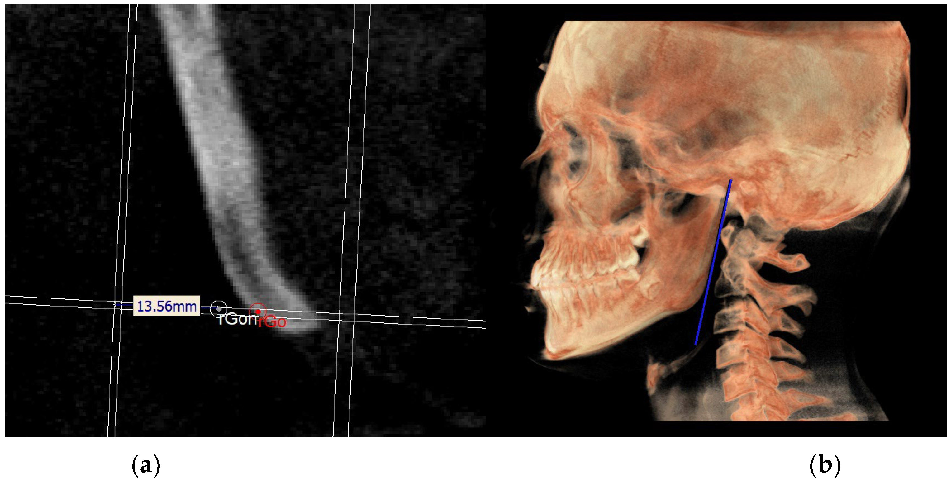
| Gon | Gonion neutral: the point located at the same level of the Go and halfway between the PMn line and its parallel passing through Ar |
| Lines | |
| PMn | PM neutral: the line parallel to the PM forming at the point SEn an ideal angle of 40.3° with the MCFn |
| MCFn | MCF neutral, Ar—Sen |
| MRn | MR neutral, Ar—Gon |
| FOPn | FOP neutral, plane perpendicular to the PMn passing through Poc |
| Point. | X (Left to Right) Sagittal View | Y (Superior to Inferior) Axial View | Z (Posterior to Anterior) Coronal View |
|---|---|---|---|
| Middle cranial floor, right side (rMCF) | Point in superior and endocranial surface where greater wings of sphenoid cross anterior cranial floor at posterolateral bony wall of right orbit | Anterior-most point of middle cranial floor (endocranial surface of greater wings of the sphenoid), right side | Point in endocranial surface where greater wing of sphenoid crosses anterior cranial floor at lateral bony wall of right orbit |
| Middle cranial floor, left side (lMCF) | Point in superior and endocranial surface where greater wings of sphenoid cross anterior cranial floor at posterolateral bony wall of left orbit | Anterior-most point of middle cranial floor (endocranial surface of greater wings of the sphenoid), left side | Point in endocranial surface where greater wing of sphenoid crosses anterior cranial floor at lateral bony wall of left orbit |
| Basion (Ba) | Most anterior point of foramen magnum | Most anterior point of foramen magnum | Most anterior point of foramen magnum |
| Right condylion (rCo) | Most posterior point of mandibular condyle, right side | Most posterior point of mandibular condyle, right side | Most posterior point of mandibular condyle, right side |
| Left condylion (lCo) | Most posterior point of mandibular condyle, left side | Most posterior point of mandibular condyle, left side | Most posterior point of mandibular condyle, left side |
| Middle point between right and left Co (mCo) | Middle point between the two condylion | Middle point between the two condylion | Middle point between the two condylion |
| Right gonion (rGo) | Point at inferior border of mandibular angle at mid-distance between posterior-inferior-most point of ramus and inferior-posterior-most point of mandibular body, right side | Middle-posterior-most point of mandibular angle, right side | Middle-inferior-most point of mandibular angle, right side |
| Left gonion (lGo) | Point at inferior border of mandibular angle at mid-distance between posterior-inferior-most point of ramus and inferior-posterior-most point of mandibular body, left side | Middle-posterior-most point of mandibular angle, left side | Middle-inferior-most point of mandibular angle, left side |
| Posterior nasal spine (PNS) | Most posterior point of the hard palate | Most posterior point of the hard palate | Most posterior point of the hard palate |
| Posterior occlusal contact, right side (rPoc) | Most supero-distal contact point of the first molars, right side | / | / |
| Posterior occlusal contact, left side (lPoc) | Most supero-distal contact point of the first molars, left side | / | / |
| Anterior occlusal contact, right side (rAoc) | Most mesial contact point between the first premolars, right side | / | / |
| Anterior occlusal contact, left side (lAoc) | Most mesial contact point between the first premolars, left side | / | / |
| Middle point between right and left Aoc (mAoc) | Middle point between the rAoc and lAoc | Middle point between the rAoc and lAoc | Middle point between the rAoc and lAoc |
| Point | X (Left to Right) Sagittal View | Y (Superior to Inferior) Axial View | Z (Posterior to Anterior) Coronal View |
|---|---|---|---|
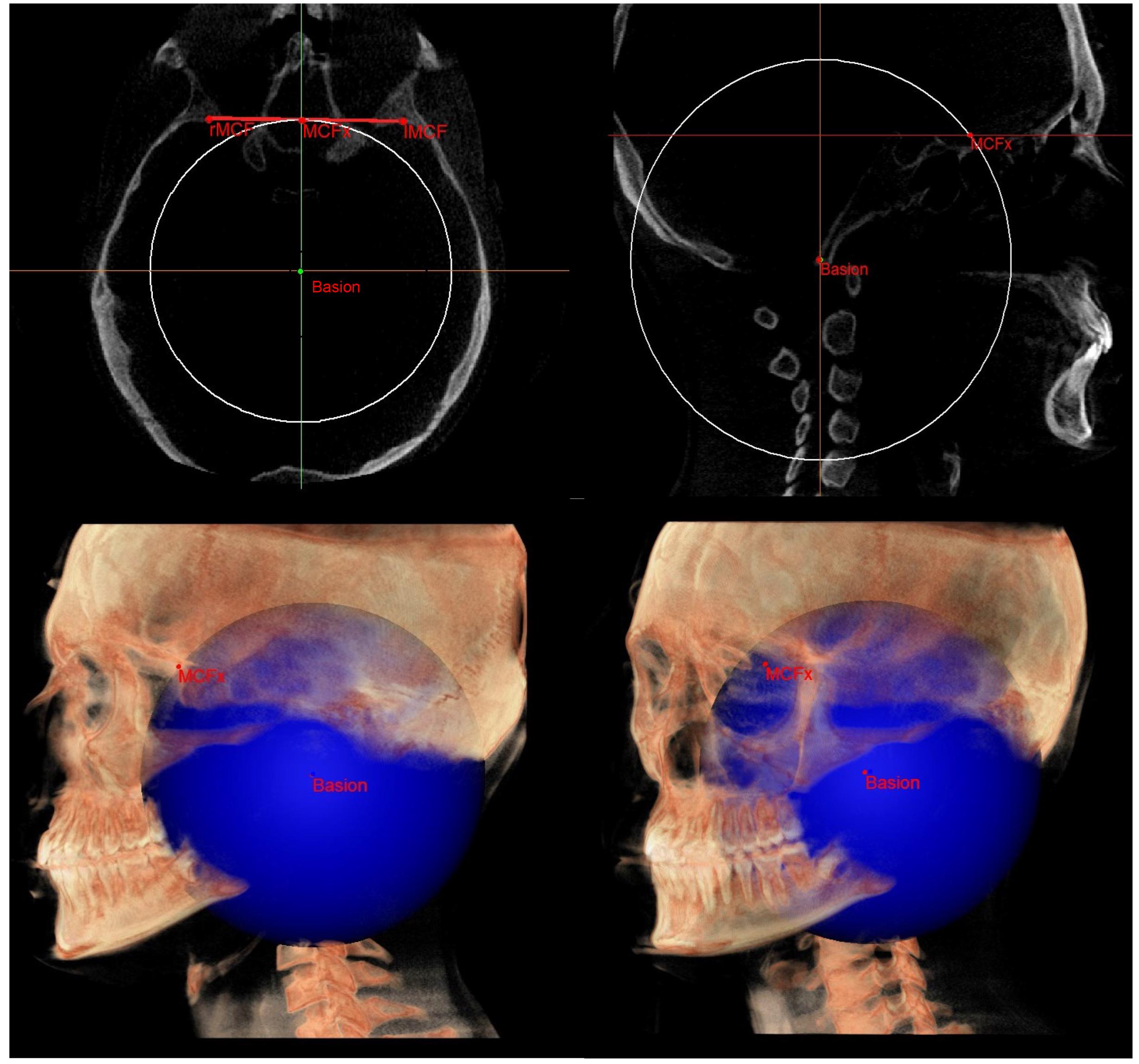
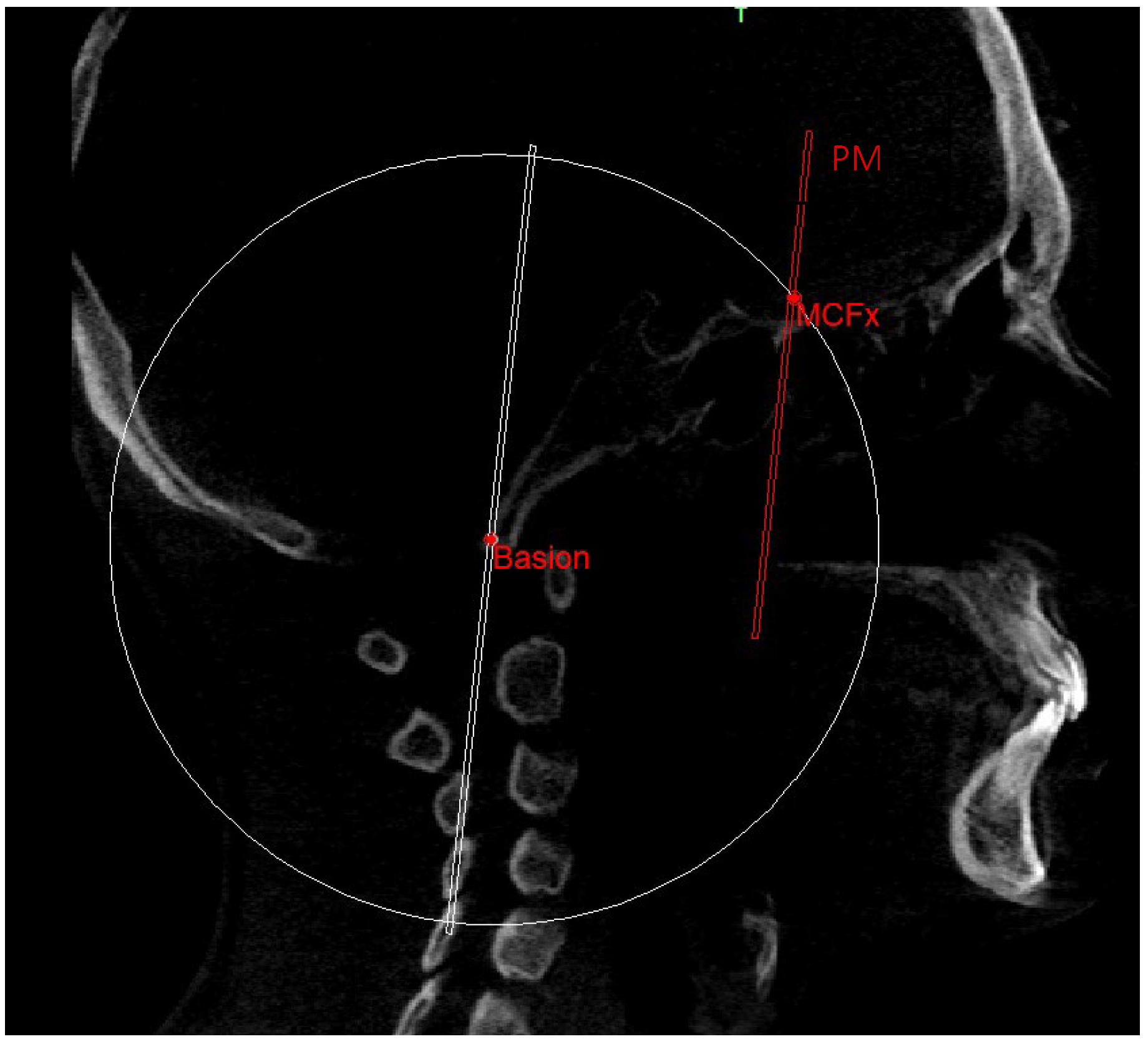
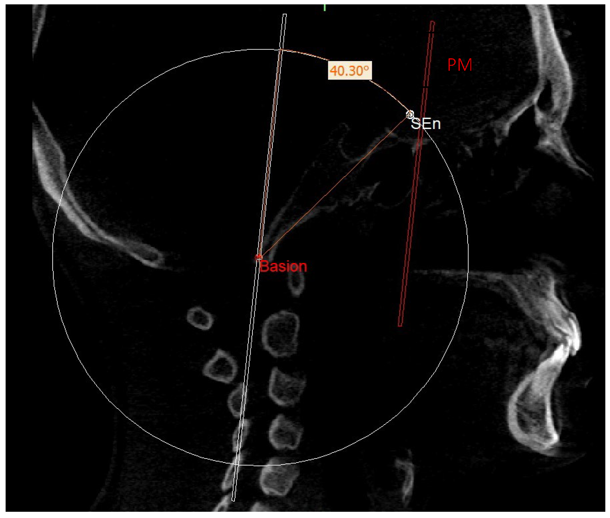
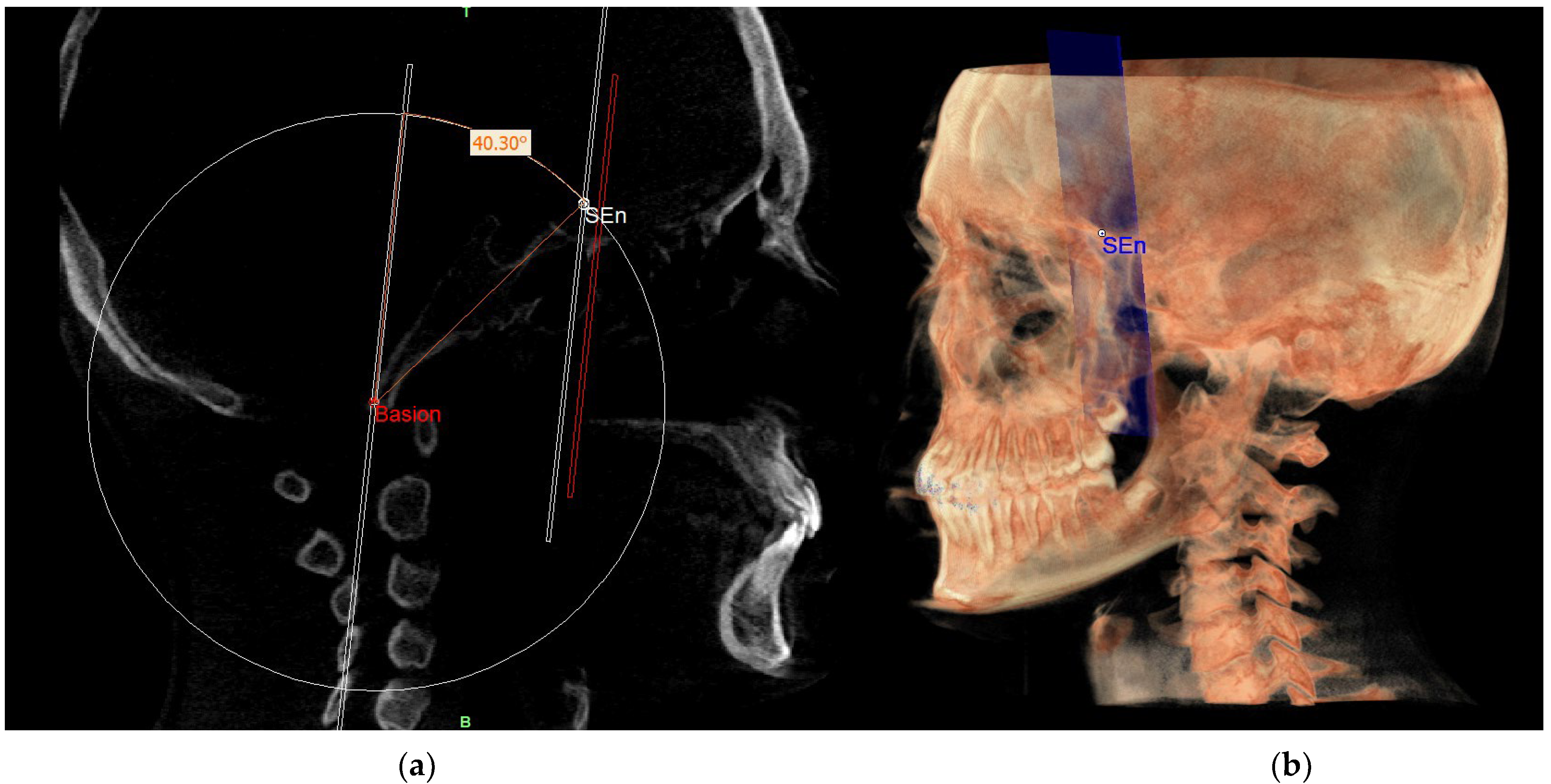
| SE neutral (SEn) | / | Point of a circumference with center in Ba and radius equal to MCFx, in which an angle of the skull base equal to 40.3° is obtained | / |
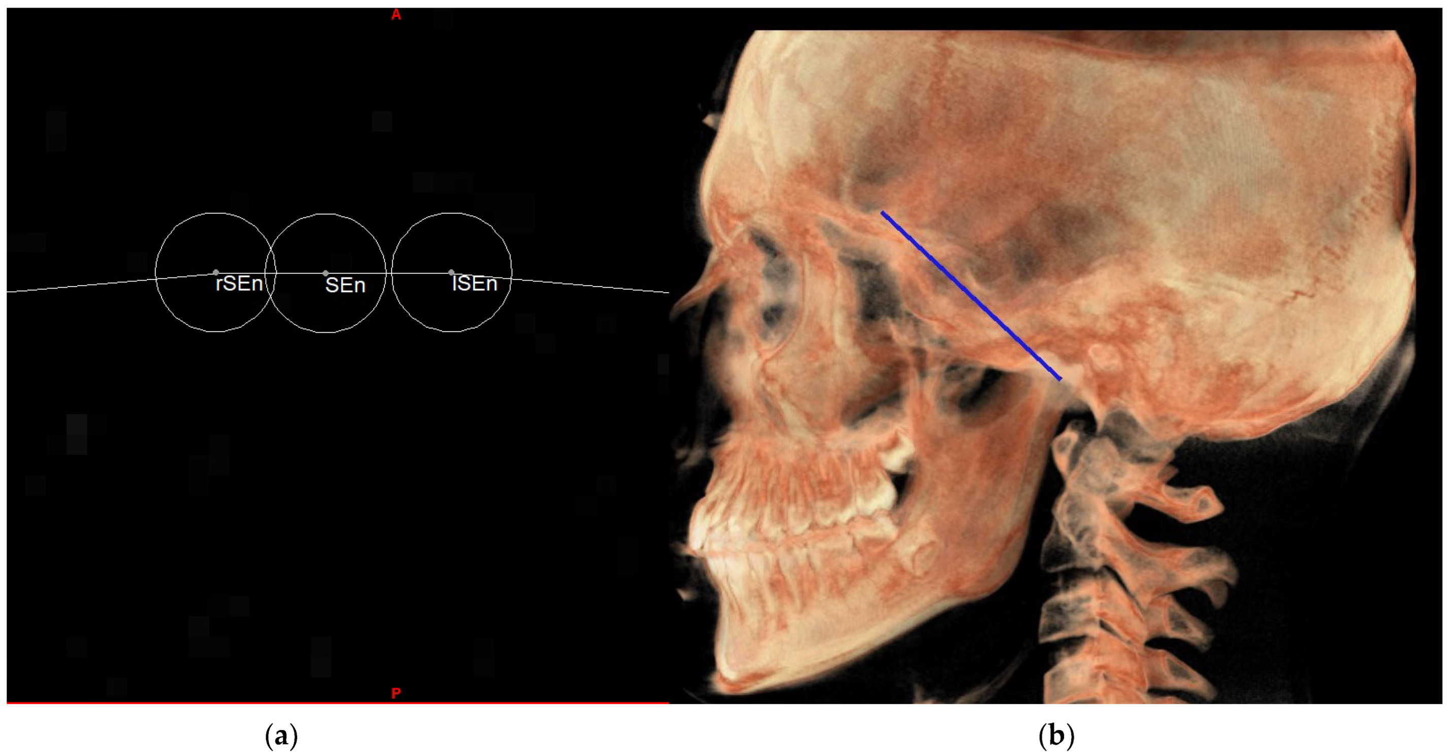
| Right SE neutral (rSEn) | / | Point taken arbitrarily on the right side of the SEn on the same arc of circumference | / |
| Left SE neutral (lSEn) | / | Point taken arbitrarily on the left side of the SEn on the same arc of circumference | / |
| Middle point MCF (MCFx) | / | Point of intersection between the plane on which the Ba lies and a line joining the left and right MCF | / |
| Neutral right gonion (rGon) | Point located at the same level of the Go and halfway between the PMn line and the CPCo plane. Right side | / | / |
| Neutral left gonion (lGon) | Point located at the same level of the Go and halfway between the PMn line and the CPCo plane. Left side | / | / |
| Planes | |
|---|---|
| Plane | Description |
| MCF neutral (MCFn) | Plane passing through the Ba, rSEn and lSEn which forms an angle of 40.3° with the PMn at the SEn point |
| PM neutral (PMn) | Plane parallel to the PM such as to form an ideal angle of 40.3° with the MCFn at the SEn point |
| MR neutral (MRn) | Plane passing through the mCo, rGon and lGon |
| FOP neutral (FOPn) | Plane normal to the PMn passing through rPoc and lPoc |
| Construction plane through Ba (CPBa) | Construction plane passing through Ba and parallel to the PM |
| Construction plane through Co (CPCo) | Construction plane passing through the mCo and parallel to the PMn |
| GoP | Gonion plane: plane passing through rGo and lGo normal to PMn |
| Index | 2D (Mean ± SD) | 3D (Mean ± SD) | p Value a |
|---|---|---|---|
| MCF ^ PM | 43.89° ± 4.25° | 43.20° ± 4.08° | 0.62 |
| MCF ^ RM | 119.40° ± 8.40° | 118.8° ± 7.18° | 0.83 |
Disclaimer/Publisher’s Note: The statements, opinions and data contained in all publications are solely those of the individual author(s) and contributor(s) and not of MDPI and/or the editor(s). MDPI and/or the editor(s) disclaim responsibility for any injury to people or property resulting from any ideas, methods, instructions or products referred to in the content. |
© 2023 by the authors. Licensee MDPI, Basel, Switzerland. This article is an open access article distributed under the terms and conditions of the Creative Commons Attribution (CC BY) license (https://creativecommons.org/licenses/by/4.0/).
Share and Cite
Peluso, A.; Falone, G.; Pipitone, R.; Moscagiuri, F.; Caroccia, F.; D’Attilio, M. Three-Dimensional Enlow’s Counterpart Analysis: Neutral Track. Diagnostics 2023, 13, 2337. https://doi.org/10.3390/diagnostics13142337
Peluso A, Falone G, Pipitone R, Moscagiuri F, Caroccia F, D’Attilio M. Three-Dimensional Enlow’s Counterpart Analysis: Neutral Track. Diagnostics. 2023; 13(14):2337. https://doi.org/10.3390/diagnostics13142337
Chicago/Turabian StylePeluso, Antonino, Giulia Falone, Rossana Pipitone, Francesco Moscagiuri, Francesco Caroccia, and Michele D’Attilio. 2023. "Three-Dimensional Enlow’s Counterpart Analysis: Neutral Track" Diagnostics 13, no. 14: 2337. https://doi.org/10.3390/diagnostics13142337
APA StylePeluso, A., Falone, G., Pipitone, R., Moscagiuri, F., Caroccia, F., & D’Attilio, M. (2023). Three-Dimensional Enlow’s Counterpart Analysis: Neutral Track. Diagnostics, 13(14), 2337. https://doi.org/10.3390/diagnostics13142337