Abstract
Interest in multilayer windings is increasing with the application of the hairpin winding technology to the manufacturing of electrical machines. Therefore, the four-layer fractional slot concentrated winding is used for the initial design of the machine in this paper. The proposed physical model of the machine uses winding with a relatively high number of turns which is inappropriate to hairpin winding. Therefore the round-wire winding is created and the three-layer winding is derived and analyzed including the effect on the slot leakage inductance. The thermal analysis is then applied to the physical model of the machine to evaluate the slot-related thermal properties of the slot and the whole machine. The measurement is compared with the finite element analysis (FEA) and the equivalent slot thermal conductivity and heat transfer coefficients of the stator and rotor are obtained.
1. Introduction
Modern trends in the design of permanent magnet synchronous machines (PMSM) are focusing on different parts of the machine with a similar goal; increase the efficiency or the power density of the machine. Both quantities are crucial aspects of the machine design, especially in the electric vehicle industry. An increase of the efficiency of the machine (or, better, the reduction of the losses of the machine) will help to decrease the requirements for the cooling system. The reduction of the losses is also an important assumption in the increase of the power density; the density of the heat which has to be removed from the machine area increases with the decreasing volume of the machine (or increasing the power). One of the promising approaches consists of the usage of a double-stator Vernier permanent magnet machine [1], but the mechanical construction of the machine can be a limiting point. The overall influence of several input geometrical parameters on the final design is discussed in [2] to minimize the total loss of high-speed motor and the cooling surface optimization of the electric kart motor is analyzed in [3]. The modern trends of increasing the power density of the whole system are moving towards the integration of power electronics and motor into one compact device [4].
The increase of the power density can be generally achieved by three approaches. The most significant results can be reached by the increase of the speed of the machine [5]. The machine can be then directly connected to the transmission with a fixed or two-speed [6] gear ratio to obtain the required output speed. This approach emphasizes the requirements of the bearings, and often leads to the decrease of the saturation of the magnetic circuit to reduce the magnetic circuit losses or to an improved cooling system to effectively dissipate the produced heat [7].
The second category of increasing the power density is based on the usage of new materials in the magnetic circuit, winding insulation, or permanent magnets, etc. Magnetic materials with a high level of saturation and small loss density [8] enable the reduction of the volume of the stator stack which can be supported by permanent magnets with a high density of energy. Properties of insulating materials can be improved in different ways; insulation systems with higher temperature class allow the increase of the maximal temperature (up to extreme temperatures [9]). Insulation systems with high dielectric strength enable the use of a thinner insulation layer for defined input voltage.
The third category consists of the application of the new technologies to the production of the machine. It is directly linked with the previously mentioned approaches to the power density increase, e.g., the composite insulation systems or the whole technology of the insulation. A very interesting technology, especially in the automotive industry applications is the hairpin winding technology [10,11]. Hairpin windings combine the advantages of both rectangular-wire windings (high slot fill factor) often supported by missing coil insulation, and round-wire coils (semi-closed slots reducing the negative slot opening-related effects as the torque ripple and general decrease of the inductance caused by the slot openings) [12]. The biggest technological and manufacturing advantage of the hairpin windings lies in the automatization of the winding process, which can help reduce the manufacturing costs. Every turn of the coil is formed by one hairpin; multiturn coils are then assembled by the multilayer hairpin winding. It enables to create the multilayer windings with different connections to reduce the higher harmonic components or the differential leakage inductance. The number of layers (turns) is mostly limited to 6 or 8 to not to increase the number of winding connections.
Every improvement of the power density has to be supported by a sufficient cooling system. The thermal calculation is the most challenging part of the design of the electrical machine, especially in the dynamic operation as discussed in [3,7]. The calculations are often supported by mathematical models and finite element analysis (FEA). Definition of the thermal model of the slot is the crucial part of the description of the heat dissipation. The slot consists of different layers with different thermal properties [13]. The most complicated situation appears in the round-wired coils with random placement of the conductors in the slot area. The equivalent thermal parameters (thermal conductivity [14,15] heat transfer coefficients [16,17]) are often historically defined as empirical values based on the comparison of the calculation and measurement. The same methodology is also used in [18,19].
The automatization of the winding process is not focused only on the hairpin windings but can be used for every winding type. It opens up new possibilities in the winding design. A physical model of the small permanent magnet synchronous machine was designed as a multipurpose model referring to the part of the modern and challenging parts of the complex design of the electrical machine. The design of the multilayer machine is inspired by the three-layer fractional slot concentrated winding described in [20]. The precise analytical calculation of the inductance helps to evaluate the operation of the machine especially at high speed where the flux weakening operation is necessary [21]. The slot leakage inductance of fractional slot concentrated machines is often the most significant component of permanent magnet machines and, therefore, it is analyzed in this paper. A different approach to the definition of the ideal turn ratio is applied and the mathematical function describing the magnetomotive force waveform obtained is derived. The influence of the winding design on the inductance of the machine is analyzed then. The second part of the paper is focused on the thermal analysis of the machine and comparison of the calculations and measurements of the physical model to get real information about the heat transfer in the slot.
It turns out that the proper definition of the slot heat transfer coefficients is the crucial part of the thermal design of modern electric machines that often use water-cooled housing and the slot is the area of the dissipating of the heat generated in the winding. Although algorithms to increase the slot fill factor have been investigated [22], the real machines with rounded wires often have fill factor in ratio 0.35–0.45. Therefore, the experimental validation of the slot heat transfer coefficient of this physical model can be an important part of the complex thermal design of modern electric machinery.
2. Design of Three-Layer Winding
Initial universal double-layer three-phase fractional slot concentrated winding with the number of slots per pole and phase q = 1/2 is replaced by winding with q = 2/5 to reduce the parasitic effects such as cogging torque and pulsation of induced voltage and output current [23]. Unfortunately, this winding generates a higher amount of parasitic space harmonic content in comparison with the initial winding. Therefore, the possibility of space harmonic content reduction is analyzed.
Four-layer winding is obtained when two identical sets of double-layer windings are used and the sets shift by ys slots (mostly by one slot to avoid high fundamental space harmonics reduction). Current polarity in the shifted winding set has to be changed to not to get the opposite direction of currents inside one slot if the shift ys is an odd number. The principle of the four-layer winding definition is shown in Figure 1.
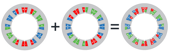
Figure 1.
Principle of four-layer winding definition.
Every slot consists of three coil sides belonging to one phase and one coil side belonging to the other winding. This slot arrangement can be divided into three single-layer winding, as shown in Figure 2.
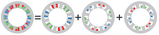
Figure 2.
Decomposition of four-layer winding to three single-layer windings.
Identical configuration of every single-layer winding can be obtained by two different windings:
- (a)
- fractional slot winding q = 2/5 with 10 poles;
- (b)
- integer slot winding q = 2 with 2 poles.
This effect is represented by the produced step curve of magnetomotive force Fm and its spectral analysis in Figure 3. The fundamental harmonic component is ν = 1 for integral slot winding and ν = 5 for fractional slot winding.
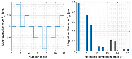
Figure 3.
Magnetomotive force step curve and its spectrum produced by single-layer winding q = 2/5 with 10 poles.
The magnetomotive force produced by integral slot windings can be mathematically described by equations derived in [24]. The resulting three-layer winding consists of three single-layer windings shifted by one slot pitch represented by angle ξs. Windings can be divided into two types; one central winding with Ncc turns per one coil and two marginal windings each with Ncm turns per coil. The produced magnetomotive force of these three single-layer windings is described as a sum
where ξ is the space angular position, ωt the time angular position, m is the number of phases and Fm1ν is the magnitude of produced magnetomotive force defined in [24]. The expression in brackets in (1) can be modified and the final mathematical description of magnetomotive force produced by three-layer winding is
where Nc is the mean number of winding turns defined as Nc = (Ncc+2Ncm)/3 and kcsν is a factor respecting the number of turns of coils and shift of winding sets equal to
Preserving the average number of coil turns Nc constant, distribution of turns into central and marginal coils is limited by two extreme situations; when marginal coils windings are not used, ratio 2Ncm/3Nc equals zero. When winding with central coils is not used, the ratio 2Ncm/3Nc equals one.
Integral slot winding produces only spatial harmonic component orders
which can be divided into two groups based on the relation between factor kcs and distribution of coils turns. The influence of the ratio of turns to factor kcs is shown in Figure 4.
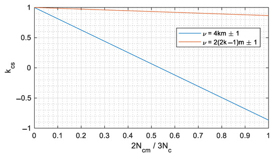
Figure 4.
Influence of turns ratio on factor kcs.
It is obvious, that harmonic component orders ν = 4 km ± 1 can be suppressed when
that is, for,
The ratio between the number of turns of the central and marginal coil is then
which corresponds to the results in [20]. The presented method allows determining of winding factor for any ratio of central and marginal coil turns. The winding factor of the fundamental harmonic component (ν = 5) derived from the initial integral slot two-pole single layer winding is k’w5 = 0.966.
The factor respecting the number of turns of coils and shift of winding sets is for the ideal ratio derived in (6) and (7):
The winding factor of optimized three-layer winding is then
The coefficient of differential leakage inductance τdiff is then reduced from the value 0.97 (two-layer winding) to 0.84.
2.1. Slot Leakage Inductance
Coil sides in some slots belong to different phases if coils with short pitch are used for the multilayer windings. The total energy of the magnetic field stored in these slots decreases and also the slot leakage inductance Lσs. This inductance reduction is respected by coefficients kCu for the active slot area and kke for the slot opening area. These coefficients are derived in [25] for double-layer winding and are widely used in the literature.
The leakage inductance in the slot depends on the number of coil sides belonging to one phase and the placement of these coil sides in the slot. Possible coil side placements in the slot are summarized in Figure 5.
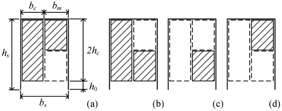
Figure 5.
Overview of possible coil sides belonging to one phase placements in one slot: central and one marginal coil (a,b), and only marginal coil (c,d).
Coil widths bc and bm are defined by total slot width bs and number of turns Nc and Nm as
The analytical integral solution of magnetic energy stored in the slot is evaluated for all combinations in Figure 5. The total magnetic energy produced by analyzed winding is compared with theoretical full-slot winding and the dependency of coefficients kCu and kke for different Ncc/Ncm ratios is shown in Figure 6.
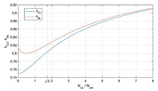
Figure 6.
Dependency of coefficients kCu and kke on the turns ratio.
Similar approach can be generalized to different number of coil sides in one slot; the arrangement of the coil sides belonging to one phase in the slot has to be summarized (according to Figure 5) and ratio of the energy of magnetic field respecting the coil position to theoretical full-slot winding defined the coefficients kCu and kke. A typical example of multilayer windings are the hairpin winding analyzed e.g., in [10].
2.2. Physical Model of the Permanent Magnet Synchronous Machines (PMSM) with Three-Layer Winding
A small stator stack with the dimensions shown in Figure 7 is used for the physical model of PMSM with the designed three-layer winding. The stack is made of M800-50A electrical steel with the Suralac 5012 insulation and the stack length is lFe = 40 mm.
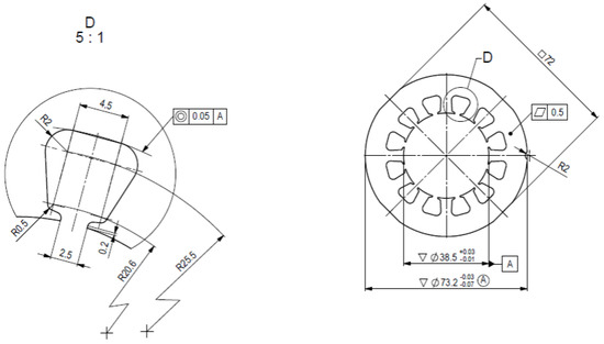
Figure 7.
Dimensions of the stator stack.
The final hand-made stator winding consists of Ncc = 52 and Ncm = 30 turns. The real ratio of the number of turns of the central and marginal coil is Ncc/Ncm = , and the relative difference between the ideal value (7) and real value is smaller than 0.1%. The machine is then designed including the calculation of the equivalent circuit parameters [14] and the design is validated by the finite element analysis.
The lining of the slots is achieved by the Kapton tape (Figure 8a) and the inter-turn insulation is ensured only by the double-layer wire insulation. The color emphasis of different phases is shown in Figure 8b The rotor yoke is created by the construction steel sheets and the surface-mounted permanent magnets are glued to the yoke, see Figure 8c.
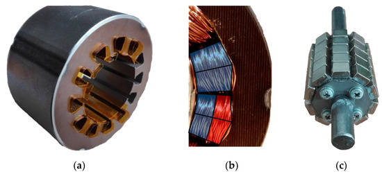
Figure 8.
Parts of the machine: stator with partially inserted slot insulation layer (a), detailed look at the wound stator with highlighted coils belonging to different phases (b), and rotor with mounted permanent magnets (c).
The machine was built and measured under the no-load and short circuit operation to measure the equivalent circuit parameters. Comparison of the measurement of the back EMF with the FEA results is shown in Figure 9a Reference machine with double-layer winding q = 1/2 was built in parallel and the reader can compare the back-EMF waveforms obtained by both windings in Figure 9. The harmonic content of the back EMF waveforms obtained by the FEA and measurement is almost identical for both windings. Even from the shape of the waveforms, it is evident that the modified three layer winding (a) generates a smaller amount of spatial higher harmonic components.
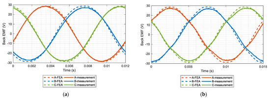
Figure 9.
Comparison of the back-EMF of the winding with q = 2/5 (a) and q = 1/2 (b).
3. Thermal Analysis of the Machine
The thermal analysis has been made in two steps. The non-rotating machine was loaded by the direct current and measured at first to obtain the equivalent coefficient of the thermal conductivity of the handmade winding placed in the stator slot. The second test consists of the generator operation with the winding loaded by the resistive load. This thermal analysis of the rotating machine is focused on the definition of the real heat transfer coefficient of the stator and rotor surface gap.
3.1. Thermal Analysis of Steady-State Non-Rotating Machine
This steady-state thermal analysis of the machine enables to focus only on the losses produced by the stator winding and heat transfer to the stator core neglecting the additional cooling effects caused by the rotating rotor. Therefore, this analysis is a proper approach to evaluate the equivalent thermal conductivity of the winding.
The 3D mathematical model of the machine is created at first for the comparison with the measurement of the physical model. It is important not to exceed these limits:
- maximal temperature of the winding 150 °C defined by the temperature class of used winding insulation;
- maximal permanent magnet temperature defined by the Curie temperature of the magnet.
The maximal temperature of the winding insulation is the limiting factor in this measurement.
The windings of all three phases are connected in series to ensure the uniform distribution of the joule losses in the machine. The winding is loaded by a direct current to suppress the core losses and additional magnetic field-related and frequency-related losses.
The temperature of the permanent magnets and especially the temperature of the stator core and the winding is measured during the test. The thermographic camera picture is presented in Figure 10. This method of temperature measurement is chosen for a fast temperature check and comparison of the thermal dissipation of the machine with mathematical models.
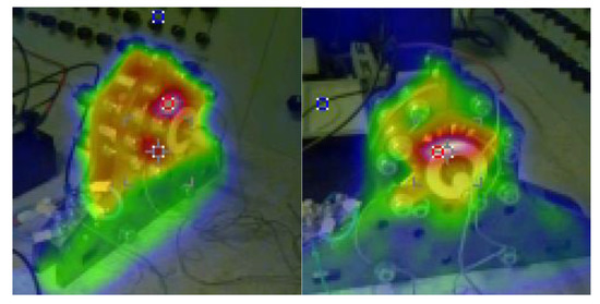
Figure 10.
Non-contact measurement of the machine temperature by the thermal camera during the non-rotating tests loaded by DC (nominal current).
The problem of the equivalent conduction coefficients could be reduced to the 2D geometry; the temperatures are, therefore, measured from the axial direction respecting the cross section of the machine. The slot area can be described as a composite material with different thermal properties of the parts and roughly known position of every single part. The definition of the equivalent thermal conductivity of the wired coil with relatively small fill factor of the slot and random positioning of the wires in the slot represents the most challenging task.
The equivalent conductivity of the slot depends on the location of every wire in the slot area. It is considered that the random positioning of the wires in the slot area defines many possibilities of the arrangement of every single wire (touching the slot wall, touching one other wire, etc.). The winding arrangement can be generally different for every slot and every machine and it directly affects the equivalent thermal conductivity of the whole slot. Different models of the location of the wires could be applied; the uniform distribution of the wires [26] is applied in this paper.
The homogenous model of the slot is created; the slot area is replaced by the concentric circles respecting the area of (copper and wire insulation of all conductors in the stator slot plus Kapton tape added in the slot) and the surrounding air [15,27] (see Figure 11). The number of conductors and their area of the cross-section is then represented by circles. All dimensions refer to the real topology; the cross-section is shown in Figure 7. Radius of the equivalent copper layer and width of the insulation and Kapton tape annular layers are defined by the sum of the real materials between the center of the slot and the slot wall; these values are constant in both tangential and radial directions.
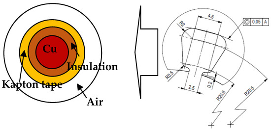
Figure 11.
Scheme of homogenization of the stator slot with geometrical dimensions.
The equivalent thermal conductivity of the solid materials in the slot is then calculated as:
where bw is the equivalent width of the copper layer, bi is the equivalent width of the wire insulation layer and bk is the equivalent width of the Kapton tape layer.
This reduction of the stator slot and winding to the concentric circles enables to obtain the equivalent thermal conductivity (based on the Equation (11)) in both radial and tangential directions as λekv = 2.48 Wm−1K−1. This equivalent thermal conductivity represents an ideal situation when all wires are currently touching surrounding wires and the surface of the slot and the heat has to pass from the exact center of the stator slot to its wall.
In the solved thermal model is on the machine surface and the rotor face set the heat transfer coefficient to αoutside = 9 Wm−2K−1. The other parameters are presented in Table 1. The ANSYS Workbench is used for the calculation.

Table 1.
Used parameters for simulation setup.
The wires are surrounded by the air in the slot and the equivalent air layer (Figure 11) with the equivalent conductivity λair is used as a correction factor between the ideal and real situation. The air layer is not directly defined by the real width of the air layer in the slot in comparison with the copper and insulation parts; its final value will be defined by the comparison of the measurement and 3D Finite Element Analysis (FEA). Both the equivalent width of the air layer ba and the equivalent thermal conductivity λa are the unknown values. The equivalent width ba will be derived from the 3D FEA model (see Figure 12) and the initial value of the thermal conductivity is analytically calculated.
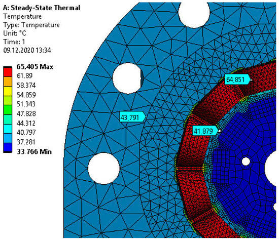
Figure 12.
FEA simulation results of the obtained equivalent conductivity coefficient.
The maximal operating temperature of the winding which cannot be exceeded during the measurement is 150 °C. The applied direct current of 1 A generates the joule losses which excite the steady-state temperatures 64.9 °C for the winding, 41.8 °C for the magnets, and 44.0 °C for the stator core. The same losses are used in the 3D FEA parametrical calculation and the final value of the equivalent thermal conductivity of the air λair is iteratively obtained based on the comparison of the 3D FEA and measurement.
Comparison of the obtained temperature values is summarized in Table 2. The temperature distribution for the final value of the λair is shown in Figure 12.
Table 2.
Comparison of the calculation and measurement—non-rotating machine.
The equivalent thermal conductivity of the air of this machine is calculated as λair = 0.042 Wm−1K−1. This value is used for space (air) between the coil and the stator slot and stator yoke and the maximal relative difference (see the Table 2) of the measurement and 3D FEA is smaller than 4%. It is a good result for the non-homogeneous wired coil. The difference between the contact and contactless measurement is the influence of the emissivity settings of the thermal camera. The two calculated coefficients λekv and λair have a strong impact on the results of the DC thermal test with a stopped machine.
The final thermal conductivity of the whole slot λslot is calculated by an equation equivalent to (11) and the final value is λslot = 0.54 Wm−1K−1. This value fits the range of thermal conductivities obtained by a similar approach presented in [13]. The diagram of the steps in solution is presented in Figure 13.
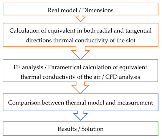
Figure 13.
Diagram of the solution of the thermal model.
3.2. Thermal Analysis of Steady-State Rotating Machine
The thermal conductivity of the slot represents the conductive heat transfer between the winding and the stator core. The cooling effect of the rotating rotor and thermal convection between the stator, rotor, and surrounding air are defined by the heat transfer coefficient α. The precise definition of this coefficient and the boundary conditions influence the correctness of the results obtained by FEA.
Two elementary equations are used for the exact setting of the heat transfer coefficient. This can be calculated by the usage of the heat flux density qhtc and temperature difference as:
where T is the temperature of the analyzed part of the machine, and Tamb is ambient temperature. The heat transfer coefficient also defines the thermal heat transfer resistance Rp as [28]
where A is area of the surface.
The calculation of the heat transfer coefficient α is strongly dependent on many aspects, e.g., the dimensions of the machine, surface area, and other mechanical properties, shape, material, speed of the medium, thermal conductivity, etc. The dimensionless quantities are used in the analytical and numerical calculations to quantify the thermal convection; the Reynold’s (Re) and Nusselt (Nu) numbers are used in this paper. The formulas used for estimation of the heat transfer coefficient α are different, empirical, and defined differently in every literature [16,28,29]. Individual empirical relations have to be used for every part of the machine. The formula for the Reynold’s number applied to the outer surface of the permanent magnet (rotor of the machine) is:
where D is the diameter of the outer rotor surface, v is the sped of the coolant and νk is the kinematic viscosity of the air. Nusselt’s number is calculated according to [28,29].
The tested speed of the machine is ns = 1000 rpm. The empirically calculated heat transfer coefficients are αst in = 44 Wm−2K−1 for the inner stator surface and αrot out = 24 Wm−2K−1 for the rotor outer surface. These coefficients are based on the formulas from literature [14,16,17]. These values are confirmed by the 3D computational fluid dynamics (CFD) simulation of the rotating machine (see Figure 14).
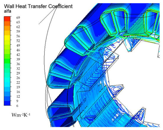
Figure 14.
Computational fluid dynamics (CFD) simulation results of the heat transfer coefficient—rotating machine.
The calculated equivalent thermal conductivity of the slot and heat transfer coefficients of the stator and rotor surface are applied to the 3D steady-state FEA of the rotating machine. The usage of Reynold’s and Nusselt’s numbers respects the laminar or turbulence character of the air flowing in the air gap. The maximal steady-state output current is defined to Imax = 1.5A (rms current) at the reference speed 1000 rpm per one phase; this value and excited losses are used for the analysis. Comparison of the results obtained by the measurement and 3D FEA is summarized in Table 3 and the temperature distribution is shown in Figure 15.
Table 3.
Comparison of the calculation and measurement—rotating machine.
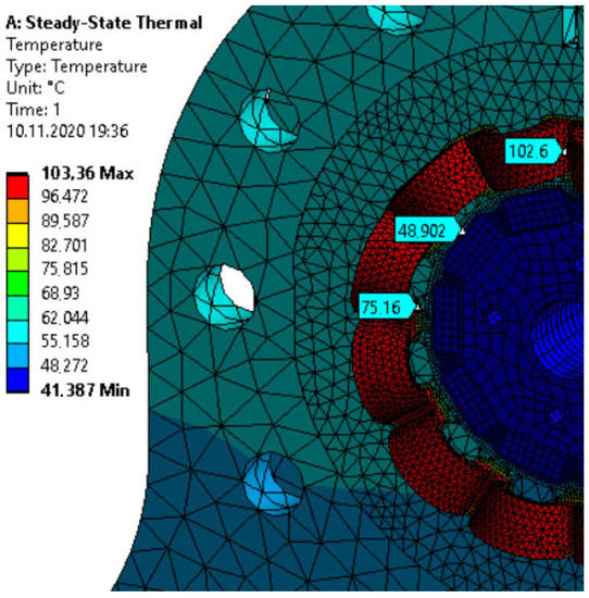
Figure 15.
FEA simulation results of the obtained equivalent conductivity coefficient—rotating machine.
The heat transfer coefficients were derived in previous calculations and directly used in this 3D FEA analysis of the rotating machine. The approach used is validated by the comparison of the temperature distribution obtained by the 3D FEA and measurement of the loaded rotating machine. The obtained error of measured and calculated values are smaller than 3%.
4. Conclusions
A physical model of the permanent magnet synchronous machine has a relatively high number of turns in the slot; the round wire winding is, therefore, used with an optimized turn ratio of this multilayer winding; The ideal ratio of the number of turns of the central and marginal coil is √3, which corresponds to [20]; the winding factor of spatial harmonic components ν = 4 km ± 1 is then zero according to Figure 4 and the parasitic components of the produced magnetomotive force waveform are therefore reduced. The presented mathematical description of the step curve of the magnetomotive force can be modified and generally applied to the four-layer hairpin windings. One of the overlooked factors of these multilayer windings is the influence of the arrangement of the coil sides to the slot leakage inductance; it has been evaluated for different turn ratios and can be also applied to the four-layer hairpin winding.
The round-wired coils generally have a small fill factor of the slot and the random positioning of the wires in the slot. The physical model is used for the evaluation of the thermal properties of the slot. It is necessary to use the combination of the analytical, FEA, and CFD calculations, and the results are then iteratively obtained by the usage of a combination of the presented methods. The obtained thermal conductivity of the slot is λslot = 0.54 Wm−1K−1 and the heat transfer coefficients for a rotating machine are αst in = 44 Wm−2K−1 and αrot out = 24 Wm−2K−1 for inner stator surface and outer rotor surface, respectively. The maximal stable output power of this physical model is approximately 30 W at the reference speed 1000 rpm.
The paper presents a method for the analytical description of the magnetic field produced by a multilayer winding, and an approach to the precise calculation of the slot leakage inductance, which is necessary to the calculation and prediction of the operation maps of the machine. The multilayer windings can have different configuration but presented approach can be modified to different winding.
The calculated value of slot heat transfer coefficient can be used by a reader for a comparison with their own calculations and measurements of machines with similarly small slot filling factor. The authors will compare the obtained results with other machines and the results will be applied to the thermal design and analysis of the machines with similar winding designed for use in industrial applications.
Author Contributions
Conceptualization, J.L., L.V. and R.P.; methodology, L.V; validation, measurements J.L., L.V.; writing—original draft preparation, J.L., L.V.; writing—review and editing, R.P.; visualization, J.L.; supervision, R.P. All authors have read and agreed to the published version of the manuscript.
Funding
This research has been supported by the Ministry of Education, Youth and Sports of the Czech Republic under the project OP VVV Electrical Engineering Technologies with High-Level of Embedded Intelligence CZ.02.1.01/0.0/0.0/18_069/0009855 and funding program of the University of West Bohemia number SGS 2021-021.
Institutional Review Board Statement
Not applicable.
Informed Consent Statement
Not applicable.
Data Availability Statement
Not applicable.
Conflicts of Interest
The authors declare no conflict of interest.
References
- Vali, M.; Niknam, T.; Gorginpour, H.; Bahmani-Firouzi, B. Optimal Design Procedure of a High-Torque-Density Dual-Stator Consequent-Pole Vernier PM Machine. Electr. Eng. 2020, 102, 2637–2653. [Google Scholar] [CrossRef]
- Popescu, M.; Foley, I.; Staton, D.A.; Goss, J.E. Multi-Physics Analysis of a High Torque Density Motor for Electric Racing Cars. In Proceedings of the 2015 IEEE Energy Conversion Congress and Exposition (ECCE), Montreal, QC, Canada, 20–24 September 2015; pp. 6537–6544. [Google Scholar] [CrossRef]
- Hruska, K.; Kindl, V.; Pechanek, R. Design of a High-Speed Permanent Magnet Synchronous Motor for Electric Kart. Electr. Eng. 2017, 99, 1141–1150. [Google Scholar] [CrossRef]
- Schiestl, M.; Marcolini, F.; Incurvati, M.; Capponi, F.G.; Starz, R.; Caricchi, F.; Rodriguez, A.S.; Wild, L. Development of a High Power Density Drive System for Unmanned Aerial Vehicles. IEEE Trans. Power Electron. 2021, 36, 3159–3171. [Google Scholar] [CrossRef]
- Liu, P.; Feng, S. Integrated Motor and Two-Speed Gearbox Powertrain System Development for Electric Vehicle. In Proceedings of the 2020 IEEE Energy Conversion Congress and Exposition (ECCE), Detroit, MI, USA, 11–15 October 2020; pp. 1499–1504. [Google Scholar] [CrossRef]
- Ou, J.; Liu, Y.; Breining, P.; Gietzelt, T.; Wunsch, T.; Doppelbauer, M. Experimental Characterization and Feasibility Study on High Mechanical Strength Electrical Steels for High-Speed Motors Application. IEEE Trans. Ind. Appl. 2021, 57, 284–293. [Google Scholar] [CrossRef]
- Wohlers, C.; Juris, P.; Kabelac, S.; Ponick, B. Design and Direct Liquid Cooling of Tooth-Coil Windings. Electr. Eng. 2018, 100, 2299–2308. [Google Scholar] [CrossRef]
- Ueno, S.; Enokizono, M.; Mori, Y.; Yamazaki, K. Vector Magnetic Characteristics of Ultra-Thin Electrical Steel Sheet for Development of High-Efficiency High-Speed Motor. IEEE Trans. Magn. 2017, 53, 1–4. [Google Scholar] [CrossRef]
- Iosif, V.; Roger, D.; Duchesne, S.; Malec, D. An Insulation Solution for Coils of High Temperature Motors (500 °C). In Proceedings of the 2016 IEEE International Conference on Dielectrics (ICD), Montpellier, France, 3–7 July 2016; Volume 1, pp. 297–300. [Google Scholar] [CrossRef]
- Berardi, G.; Bianchi, N. Design Guideline of an AC Hairpin Winding. In Proceedings of the 2018 XIII International Conference on Electrical Machines (ICEM), Alexandroupoli, Greece, 3–6 September 2018; pp. 2444–2450. [Google Scholar] [CrossRef]
- Wirth, F.; Fleischer, J. Influence of Wire Tolerances on Hairpin Shaping Processes. In Proceedings of the 2019 9th International Electric Drives Production Conference (EDPC), Esslingen, Germany, 3–4 December 2019. [Google Scholar] [CrossRef]
- Jung, D.S.; Kim, Y.H.; Lee, U.H.; Lee, H.D. Optimum Design of the Electric Vehicle Traction Motor Using the Hairpin Winding. In Proceedings of the 2012 IEEE 75th Vehicular Technology Conference (VTC Spring), Yokohama, Japan, 6–9 May 2012. [Google Scholar] [CrossRef]
- Boglietti, A.; Carpaneto, E.; Cossale, M.; Popescu, M.; Staton, D.; Vaschetto, S. Equivalent Thermal Conductivity Determination of Winding Insulation System by Fast Experimental Approach. In Proceedings of the 2015 IEEE International Electric Machines & Drives Conference (IEMDC), Coeur d’Alene, ID, USA, 10–13 May 2016; pp. 1215–1220. [Google Scholar] [CrossRef]
- Pyrhonen, J.; Jokinen, T.; Hrabovcova, V. Design of Rotating Electrical Machines, 2nd ed; Wiley: Chichester, UK, 2013; p. 612. ISBN 978-1-118-58157-5. [Google Scholar]
- Ayat, S.; Liu, H.; Kulan, M.; Wrobel, R. Estimation of Equivalent Thermal Conductivity for Electrical Windings with High Conductor Fill Factor. In Proceedings of the 2018 IEEE Energy Conversion Congress and Exposition (ECCE), Portland, OR, USA, 23–27 September 2018; pp. 6529–6536. [Google Scholar] [CrossRef] [Green Version]
- Shams Ghahfarokhi, P.; Kallaste, A.; Podgornovs, A.; Belahcen, A.; Vaimann, T.; Asad, B. Determination of Heat Transfer Coefficient of Finned Housing of a TEFC Variable Speed Motor. Electr. Eng. 2020, 103, 1009–1017. [Google Scholar] [CrossRef]
- Shams Ghahfarokhi, P.; Podgornovs, A.; Kallaste, A.; Cardoso, A.J.M.; Belahcen, A.; Vaimann, T.; Asad, B.; Tiismus, H. Determination of Heat Transfer Coefficient from Housing Surface of a Totally Enclosed Fan-Cooled Machine during Passive Cooling. Machines 2021, 9, 120. [Google Scholar] [CrossRef]
- Bochkarev, I.V.; Bryakin, I.V.; Khramshin, V.R.; Sandybaeva, A.R.; Litsin, K.V. Developing New Thermal Protection Method for AC Electric Motors. Machines 2021, 9, 51. [Google Scholar] [CrossRef]
- Adouni, A.; Marques Cardoso, A.J. Thermal Analysis of Low-Power Three-Phase Induction Motors Operating under Voltage Unbalance and Inter-Turn Short Circuit Faults. Machines 2021, 9, 2. [Google Scholar] [CrossRef]
- Cistelecan, M.V.; Ferreira, F.J.T.E.; Popescu, M. Three Phase Tooth-Concentrated Multiple-Layer Fractional Windings with Low Space Harmonic Content. In Proceedings of the 2010 IEEE Energy Conversion Congress and Exposition, Atlanta, GA, USA, 12–16 September 2010; pp. 1399–1405. [Google Scholar] [CrossRef]
- Jeong, M.-J.; Lee, K.-B.; Pyo, H.-J.; Nam, D.-W.; Kim, W.-H. A Study on the Shape of the Rotor to Improve the Performance of the Spoke-Type Permanent Magnet Synchronous Motor. Energies 2021, 14, 3758. [Google Scholar] [CrossRef]
- Herrmann, P.; Stenzel, P.; Vogele, U.; Endisch, C. Optimization Algorithms for Maximizing the Slot Filling Factor of Technically Feasible Slot Geometries and Winding Layouts. In Proceedings of the 2016 6th International Electric Drives Production Conference (EDPC), Nuremberg, Germany, 30 November–1 December 2016; pp. 149–155. [Google Scholar] [CrossRef]
- Farshadnia, M.; Dutta, R.; Fletcher, J.E.; Ahsanullah, K.; Rahman, M.F.; Lovatt, H.C. Analysis of MMF and Back-EMF Waveforms for Fractional-Slot Concentrated-Wound Permanent Magnet Machines. In Proceedings of the 2014 International Conference on Electrical Machines (ICEM), Berlin, Germany, 2–5 September 2014; pp. 1976–1982. [Google Scholar] [CrossRef]
- Heller, B.; Hamata, V. Harmonic Field Effects in Induction Machines; Elsevier: Amsterdam, The Netherlands, 1977; ISBN 044499856X. [Google Scholar]
- Vaske, P.; Riggert, J.H. Elektrische Maschinen Und Umformer. Teil 2. Berechnung Elektrischer Maschinen, 7th ed; B.G. Teubner: Stuttgart, Germany, 1974. [Google Scholar]
- Zeaiter, A.; Fenot, M.; Saury, D. Numerical Approach to Determining Windings’ Thermal Conductivity. In Proceedings of the 2018 XIII International Conference on Electrical Machines (ICEM), Alexandroupoli, Greece, 3–6 September 2018; pp. 1291–1296. [Google Scholar] [CrossRef] [Green Version]
- Wrobel, R.; Ayat, S.; Baker, J.L. Analytical Methods for Estimating Equivalent Thermal Conductivity in Impregnated Electrical Windings Formed Using Litz Wire. In Proceedings of the 2017 IEEE International Electric Machines and Drives Conference (IEMDC), Miami, FL, USA, 21–24 May 2017. [Google Scholar] [CrossRef]
- Incropera, F.P.; DeWitt, D.P.; Bergman, T.L.; Lavine, A.S. Fundamentals of Heat and Mass Transfer, 7th ed.; John Wiley & Sons Inc.: New York, NY, USA, 2011. [Google Scholar]
- Raju, K.S.N. Fluid Mechanics, Heat Transfer, and Mass Transfer: Chemical Engineering Practice; John Wiley & Sons, Inc.: Hoboken, NJ, USA, 2010; p. 736. [Google Scholar]
Publisher’s Note: MDPI stays neutral with regard to jurisdictional claims in published maps and institutional affiliations. |
© 2021 by the authors. Licensee MDPI, Basel, Switzerland. This article is an open access article distributed under the terms and conditions of the Creative Commons Attribution (CC BY) license (https://creativecommons.org/licenses/by/4.0/).