Abstract
In this paper, an innovative system of propulsion inspired by a rowing gesture for manual wheelchairs is shown. The innovative system of propulsion, named Handwheelchair.q, can be applied to wheelchairs employed in everyday life and to sports wheelchairs for speed races, such as Handbike and Wheelchair racing. The general features of the innovative system of propulsion and the functional designs of the different solutions are described in detail. In addition, the design of the mechanism for the transmission of motion, employed in a second prototype, Handwheelchair.q02, is presented and analysed. Finally, the dynamic model of the Handwheelchair.q has been developed in order to obtain important results for the executive design of Handwheelchair.q.
1. Introduction
Many studies [1,2,3] assert that wheelchair users suffer from upper limb injuries more frequently than the rest of the population. Since the handrim is the world’s most used manual propulsion system [4], the main causes of upper limb pain depend on the motion of the handrim system that is a pushing movement. Outdoor and indoor motor activities are extremely important for the well-being of everyone. For disabled people, motor activities [5] are also an important tool in rehabilitation from a physical and psychological point of view. Even though motor activities for disabled people are extremely important, they are not easy to practice. First of all, specific sports require specific wheelchairs [6,7,8,9,10,11,12]; secondly, the areas where the disabled can practice sport have to be properly equipped; finally, the disabled are not independent for the transportation of the wheelchair for a specific sport.
The above reasons motivated us to develop a wheelchair with an innovative system of propulsion, which not only allows for the practice of outdoor activities autonomously, but also eliminates the need of a specific wheelchair for sport.
As shown in [13], during a propulsion cycle with the handrim system, the glenohumeral contact force has high peaks. This is one of the factors that can increase the risk of injuries to the shoulders. In addition, in the Conclusions section of [14] “The latter makes tangential force propulsion not only less efficient, but also more straining for the shoulder”. Different articles compare the handrim system with alternative systems of propulsion, such as a lever system [15] and a handcycle [13].
Another approach considers the use of a rowing gesture in order to obtain the propulsion. Furthermore, the rowing stroke [16] is divided into four phases and different articles have studied the efficiency of the rowing gesture [17]. The rowing stroke is a complex movement; the muscles of the legs, trunk, back, shoulders and arms are involved. The rowing stroke can be performed by disabled athletes with different levels of spinal injuries [18]. Disabled people can perform this movement depending on the height of the spinal injuries.
In the last two years, the first prototype, named Handwheelchiar.q01 [19], was released. The first prototype tested the functioning of the innovative system of propulsion and highlighted some critical issues.
In addition to the Handwheelchair.q01, the authors of this paper have wide experience with means of mobility for disabled people [20,21].
2. Rowing Gesture: General Features
The innovative system of propulsion is inspired by the rowing gesture. One of the more important characteristics of the rowing gesture is that the drive phase is obtained using a pulling movement of the arm, instead of a pushing one, typical of handrim and lever systems. The pulling movement could be a good alternative compared to the pushing movement. In this work, a cable solution was introduced in order to realise the rowing motion as a system of propulsion. The cable solution allows users to optimise their motion based on their own individual physical characteristics.
The rowing gesture is composed of two phases. During the traction phase, the user provides power, while in the recovery phase the user goes back to the initial position.
During the traction phase shown in Figure 1, the user pulls two cables by two handles wrapped around two pulleys. Each pulley transmits the torque and rotation to the wheel by a unidirectional mechanism, named a ratchet system. A power spring, which connects the pulley to the chassis of the wheelchair, is loaded. In this phase, the angular speed of the pulley and the wheel are equal.
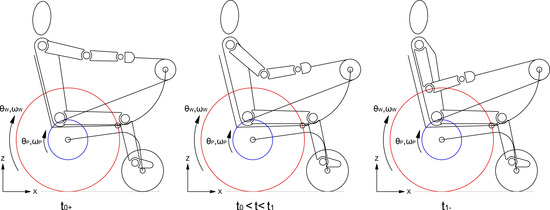
Figure 1.
Rowing gesture during the traction phase.
During the recovery phase shown in Figure 2, the user stops pulling and the power spring, previously loaded, rotates the pulleys in the opposite direction (ωw > 0, ωP < 0). The cables are wrapped around each pulley and the user can start another traction phase.
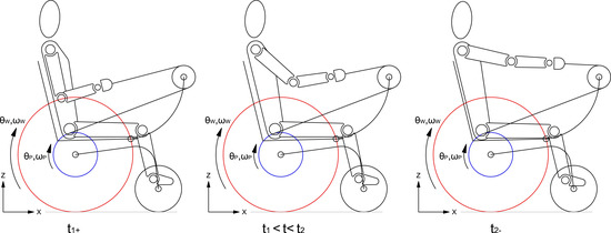
Figure 2.
Rowing gesture during the recovery phase.
In Figure 3, the angular position, the angular speed of the pulley and the wheel are shown with the three assumptions:
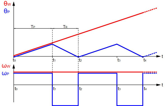
Figure 3.
Angular speed and angular position of the pulley and the wheel.
- -
- The angular speeds are constant;
- -
- The time of the traction phase TP is higher than the time of the recovery phase TR;
- -
- Pure rolling motion.
In Section 4, the mechanism of transmission of motion will be accurately described.
3. Application of the Innovative System in Sport
The innovative system of propulsion can be employed by different means of manual mobility for sport: Handbike and Wheelchair racing.
The innovative system can be installed on the Handwheelchair.q racing wheelchair, as shown in Figure 4, with a few modifications of standard racing wheelchairs. The push-rims have been removed, while a pair of traction pulleys and a pair of return pulleys have been placed. The Handwheelchair.q racing wheelchair with the innovative system of propulsion keeps the same characteristics of a racing wheelchair: two rear traction wheels and a front steering wheel.
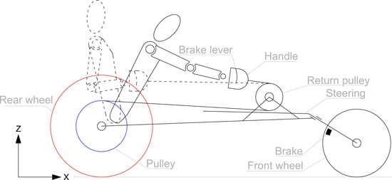
Figure 4.
Innovative system applied to the racing wheelchair.
The innovative system can be employed on the Handbike. Figure 5a shows the functional design of Handbike.q for categories H1, H2, H3 and H4, namely disabled with spinal cord injuries and Figure 5b for categories H5, namely disabled with amputated limbs. A pair of pulleys has been seated, one on each side, in order to balance the fork transversely. A return pulley has been located in order to optimise the athlete’s motion. The Handbike.q with the innovative system of propulsion retains the same characteristics of the Handbike: a traction steering front wheel.
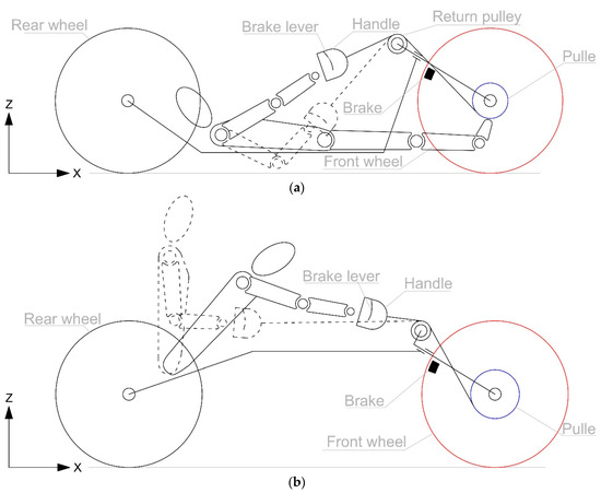
Figure 5.
(a) Innovative system applied to the recumbent Handbike; (b) Innovative system applied to the Handbike.
4. Handwheelchair.q02
The Handwheelchair.q02 is a wheelchair for everyday life. The main goals of Handwheelchair.q02 are:
- -
- To facilitate and extend outdoor movement;
- -
- To be firm and maneuverable for indoor spaces; and
- -
- To practice motor activity independently and in such areas as a park and a cycle path.
The Hanwheelchair.q02 has two configurations. The first configuration, shown in Figure 6a, is employed for indoor spaces. In this configuration, the wheelchair is used as a common wheelchair, where the propulsion is obtained by the handrim. The foldable links, left and right, that support a pair of return pulleys, are folded in order to minimise the visual impact and to allow for sitting on the wheelchair. The second configuration, shown in Figure 6b, is employed outdoors to facilitate movement, to extend accessible places and to practice motor activities. The user rotates the foldable link, left and right, around the joint C in order to obtain the innovative configuration.
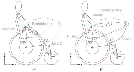
Figure 6.
(a) Handwheelchair.q02 indoor configuration; (b) Handwheelchair.q02 outdoor configuration.
Figure 7 show the components that enable the use of the wheelchair in the innovative configuration. The red component is the hub of the wheel and the blue one is the pulley around which the cable is wrapped. The green one is the power spring that connects the pulley with the chassis of the wheelchair, in grey. In the first configuration, the mechanism of transmission of motion allows the user to use the wheelchair as a common wheelchair. In fact, the hub of the wheel rotates around the shaft as in the classic wheelchair, as sketched in Figure 8a.
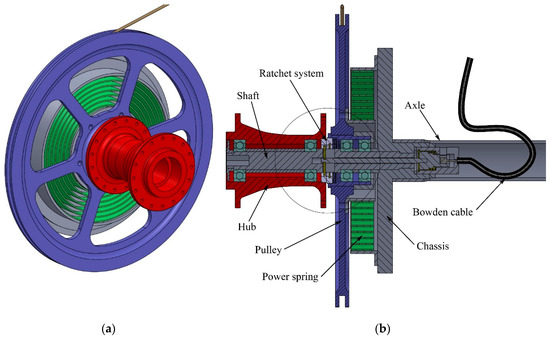
Figure 7.
(a) Components of the innovative system of propulsion; (b) Section of the mechanism.
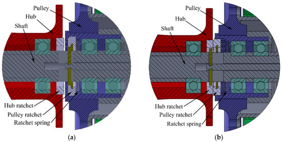
Figure 8.
Particulars of the mechanism in the (a) Classic configuration; (b) Innovative configuration.
When the user takes the handles from their site, a mechanism keeps in contact the two front ratchets, as visible in Figure 8b.
One ratchet is integrated with the pulley and the other one is mounted into the hub of the wheel. In this configuration, the propulsion is obtained by the rowing stroke previously described. During the traction phase, the user pulls the cables with a force Fu the cables are wrapped around a pair pulleys of radius rp. The user transmits a torque to the wheel through the ratchet system. During the traction phase, the user loads a power spring that connects the pulley with the chassis of the wheelchair. In Figure 9, the free-body diagrams during the traction phase of the pulley and of the hub are reported and in Table 1 and Table 2 the description of the torques and the reference systems are described.
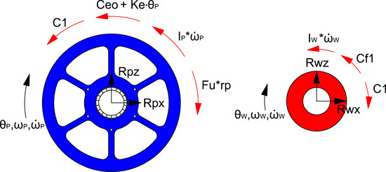
Figure 9.
Free-body diagram during the traction phase.

Table 1.
Description of the torques in the free-body diagrams.
Table 2.
Reference systems.
During the traction phase, the angular speed of the pulley is the same as the angular speed of the wheel and the equation can be written as follows:
The torque equilibrium of the pulley results:
While the torque equilibrium of the hub is:
During the recovery phase the user stops pulling, and we assume that Fu ~ 0, Figure 10. The power spring, previously loaded, has to generate a torque Ceo + Ke*θP to rotate the pulley in the opposite direction in order to rewind the cable around the pulley in a specific time TR. The recovery time TR is the parameter of the project that defines the torque of the power spring.
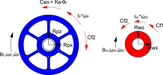
Figure 10.
Free-body diagram during the recovery phase.
During the recovery phase, the angular velocities are:
The torque equilibrium of the pulley is:
The torque equilibrium of the hub results:
5. Dynamic Model of Handwheelchair.q
In this section, according to the previous paragraph, a simplified dynamic model, Figure 11 and Figure 12, and the description of the free-body diagram, Table 3 and Table 4, of Handwheelchair.q are presented, with the following hypothesis and assumptions:
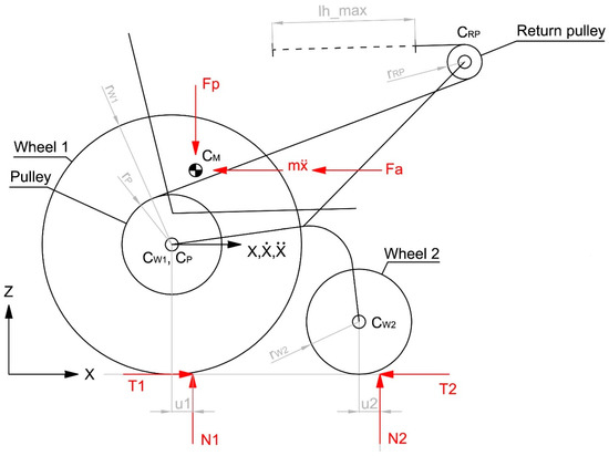
Figure 11.
Handwheelchair.q: Free-body diagram.
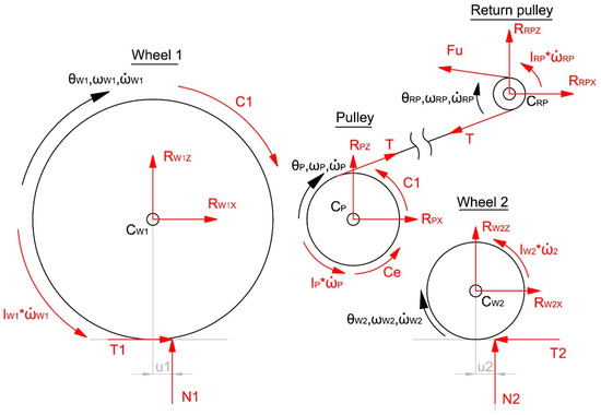
Figure 12.
Free-body diagram of wheel 1, wheel 2, the pulley and the return pulley.
Table 3.
Description of the torques and force of the dynamic model.
Table 4.
Reference system’s dynamic model.
- -
- All dynamic characteristics are concentrated on the wheel 1: N2 = 0, T2 = 0;
- -
- Even if the rolling-resistance coefficient depends on the speed [22], the rolling-resistance coefficient u1 can be assumed to be constant for low speed;
- -
- The inertia of the wheels and the pulleys is equal to zero: IW1 = 0; IW2 = 0, IP = 0; IRP = 0;
- -
- The torque of the power spring Ce is constant;
- -
- Fa is the aerodynamic force, modelled by [22], applied on the Center of Pressure; and
- -
- The Center of Pressure coincides with the Center of Mass CM.
The user’s force is modelled as follows:
- -
- The time of the traction phase is Tp and, according to Figure 13, is evaluated as:where, lh is the stroke length of the gesture and τ = 3 is the transmission ratio defined by:
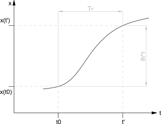 Figure 13. Time of the traction phase.
The Figure 14, shows the traction phase during the indoor test of the first prototype Handwheelchair.q01.
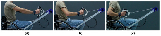
Figure 14.
Innovative gesture during the indoor test of the first prototype Handwheelchair.q01. (a) t0, lh = 0; (b) t0 < t < t1, 0 < lh < lh_max; (c) t1, lh = lh_max.
- -
- According to [12,13], during the tests the propulsion power was between 15 and 55 W. The average propulsion power for a cycle can be assumed to be between 20 and 25 W;
- -
- The user’s force Fu has been modelled with a polynomial 2-3-4 in order to define an approximate model of the “Handle force Fh” [23], as shown in Figure 15;
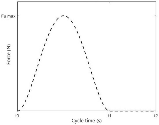 Figure 15. User’s force model.
 - -
- The scale of force Fu is determined in order to obtain the average power of 20–25 W;
- -
- The recovery time Tr is constant;
- -
- The user’s force during the recovery phase is zero.
According to the free-body diagram previously reported, and with the abovementioned hypothesis and assumptions:
The equilibrium of the wheelchair along the axis x results
The equilibrium of the wheelchair along the axis z is
The rotation equilibrium of wheel 1 around the joint Cw1 results
The rotation equilibrium of the pulley around the joint CP is
The rotation equilibrium of the return pulley around the joint CRP is
By replacing Equations (10), (11), (13) and (14) in Equation (12), it results:
By rewriting Equation (15), the acceleration can be evaluated as:
Equation (16) and the model of the user’s power have been implemented in Matlab/Simulink.
During the steady-state phase, the average wheelchair speed is constant. Figure 16 show respectively the wheelchair speed and the user’s power during a complete cycle: traction phase and recovery phase.
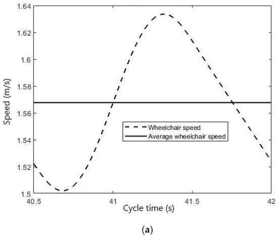
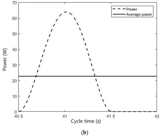
Figure 16.
Wheelchair speed (a) and user’s power (b) in a complete cycle during the steady-state phase.
The average power of 23 W and the average speed of 1.57 m/s = 5.65 km/h obtained with the simulation is in accordance with the tests carried out in [12,13,15].
By employing the user’s force model, we obtain a Fu_max = 120 N as shown in Figure 17, while the average force Fu_avg = 43 N. The force Fu is the sum of the right and left arm contribution: Fur + Ful. Then, the average force for each arm is approximately
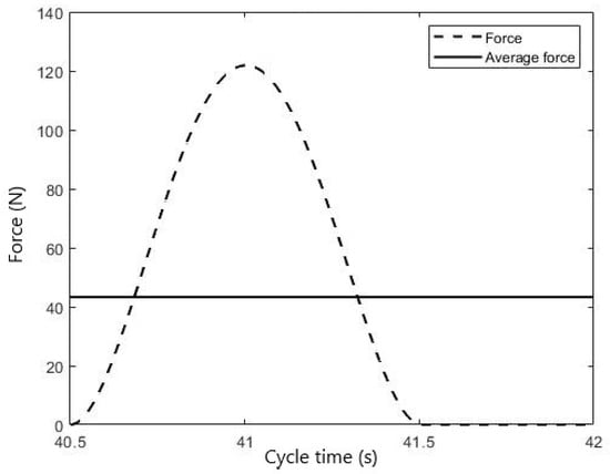
Figure 17.
User’s force during the steady-state phase.
6. Conclusions
The development of an innovative system of propulsion for manual wheelchairs is described in different possible sketches in order to be implemented in sports wheelchairs and for wheelchairs employed in everyday life. In addition, the design of the mechanism for the transmission of motion is presented. The innovative system of propulsion could be a robust idea to solve injuries on the upper limb caused by the other manual system of propulsion. The project of the prototype, named Handwheelchair.q02, is still being developed.
A simplified dynamic model has provided preliminary results in terms of force and power during a rowing stroke cycle applied to a manual wheelchair. In the future, the test data of the prototype Handwheelchair.q02 will confirm or deny these predictions.
Author Contributions
Conceptualization, G.Q. and E.B.; methodology, G.Q., E.B., P.C.; software, E.B. and P.C.; validation, G.Q.; investigation, P.C.; data curation, P.C.; writing—original draft preparation, P.C.; writing—review and editing, G.Q., E.B. and P.C.; visualization, P.C.; supervision, G.Q.; project administration, G.Q.
Funding
This research received no external funding.
Conflicts of Interest
The authors declare no conflict of interest.
References
- Lewis, A.R.; Philips, E.J.; Robertson, W.S.P.; Grimshaw, P.N.; Portus, M. Injury prevention of elite wheelchair racing athletes using simulation approaches. Proceedings 2018, 2, 255. [Google Scholar] [CrossRef]
- Curtis, K.A.; Roach, K.E.; Applegate, E.B.; Amar, T.; Benbow, C.S.; Genecco, T.D.; Gualano, J. Reliability and validity of the wheelchair user’s shoulder pain Index (WUSPI). Paraplegia 1995, 33, 595–601. [Google Scholar] [CrossRef]
- Cooper, R.A.; Boninger, M.L.; Robertson, R.N. Repetitive strain injury among manual wheelchair users. Team Rehab. Rep. 1998, 9, 35–38. [Google Scholar]
- Van Der Woude, L.H.V.; Dallmeijer, A.J.; Jansenn, T.W.J. Alternative modes of manual wheelchair ambulation: An overview. Am. J. Phys. Med. Rehabil. 2001, 80, 765–777. [Google Scholar] [CrossRef]
- Cooper, R.A.; De Luigi, A.J. Adaptive sports technology and biomechanics: Wheelchairs. Paralympic Sports Med. Sci. 2014, 6, 31–39. [Google Scholar] [CrossRef]
- Rice, I. Recent salient literature pertaining to the use of technology in wheelchair sports. Curr. Phys. Med. Rehabil. Rep. 2016, 4, 329–335. [Google Scholar] [CrossRef]
- Van Delen, C.J.R.T.; Gooch, S.; Ingram, B.J.; Borren, G.L.; Jenkins, A.; Dunn, J. Classification efficiency in wheelchair rugby: Strength analysis. Int. Fed. Autom. Control 2014, 47, 9901–9906. [Google Scholar] [CrossRef]
- Gil-Agudo, A.; Del Ama-Espinosa, A.; Crespo-Ruiz, B. Wheelchair basketball quantification. Phys. Med. Rehabil. Clin. N. Am. 2010, 21, 141–156. [Google Scholar] [CrossRef]
- Fung, Y.; Chan, D.K.; Caudwell, K.M.; Chow, B. Is the wheelchair fencing classification fair enough? A kinematic analysis among world-class wheelchair fencers. Eur. J. Adapt. Phys. Act. 2013, 6, 17–29. [Google Scholar] [CrossRef]
- Guan, T.; Lei, L.; Li, J. The human engineering analysis of the racing wheelchair. Adv. Mater. Res. 2014, 538–541, 2802–2806. [Google Scholar] [CrossRef]
- Litzenberger, S.; Mally, F.; Sabo, A. Biomechanics of elite recumbent handcycling: A case of study. Sport Eng. 2016, 19, 201–211. [Google Scholar] [CrossRef]
- Arnet, U.; Van Drongelen, S.; Van der Woude, L.H.V.; Veeger, D.H.E.J. Shoulder load during handcycling at different incline and speed conditions. Clin. Biomech. 2012, 27, 1–6. [Google Scholar] [CrossRef]
- Arnet, U.; Van Drongelen, S.; Scheel-Sailer, A.; Van der Woude, L.H.V.; Veeger, D.H.E.J. Shoulder load during synchronous handcycling and handrim wheelchair propulsion in persons with paraplegia. J. Rehabil. Med. 2012, 44, 222–228. [Google Scholar] [CrossRef][Green Version]
- Bregman, D.J.J.; Van Drongelen, S.; Veeger, H.E.J. Is effective force application in handrim wheelchair propulsion also efficient? Clin. Biomech. 2009, 24, 13–19. [Google Scholar] [CrossRef]
- Sasaki, M.; Stefanov, D.; Ota, Y.; Miura, H.; Nakayama, A. Shoulder joint contact force during lever-propelled wheelchair propulsion. Robomech J. 2015, 2, 13. [Google Scholar] [CrossRef]
- Greene, A.J.; Sinclair, P.J.; Dickson, M.H.; Colloud, F.; Smith, R.M. The effect of the ergometer design on a rowing stroke mechanics. Scand. J. Med. Sci. Sports 2013, 23, 468–477. [Google Scholar] [CrossRef]
- Pelz, P.F.; Verge, A. Validated biomechanical model for efficiency and speed of rowing. J. Biomech. 2014, 47, 3415–3422. [Google Scholar] [CrossRef]
- Smoljanovic, T.; Bojanic, I.; Pollock, C.L.; Radonic, R. Rib stress fracture in a male adaptive rower from the arms and shoulders sport class: Case report. Croat. Med. J. 2011, 52, 644–647. [Google Scholar] [CrossRef]
- Quaglia, G.; Bonisoli, E.; Cavallone, P. A proposal of alternative propulsion system for manual wheelchair. Int. J. Mech. Control 2018, 19, 33–38. [Google Scholar]
- Quaglia, G.; Nisi, M. Design of a self-leveling cam mechanism for a stair climbing wheelchair. Mech. Mach. Theory 2017, 112, 84–104. [Google Scholar] [CrossRef]
- Quaglia, G.; Franco, W.; Nisi, M. Design of a reconfiguration mechanism for an electric stair-climbing wheelchair. In Proceedings of the ASME IMECE 2014 International Mechanical Engineering Congress and Exposition, Montreal, QC, Canada, 14–20 November 2014; p. V04AT04A022. [Google Scholar]
- Baldissera, P. Proposal of a coast_down model including speed-dependent coefficients for the retarding forces. Proc. Inst. Mech. Eng. Part P 2017, 231, 154–163. [Google Scholar]
- Turpin, N.A.; Guèvel, A.; Durand, A.; Hug, F. Effect of power output on muscle coordination during rowing. J. Appl. Physiol. 2011, 111, 3017–3029. [Google Scholar] [CrossRef]


© 2019 by the authors. Licensee MDPI, Basel, Switzerland. This article is an open access article distributed under the terms and conditions of the Creative Commons Attribution (CC BY) license (http://creativecommons.org/licenses/by/4.0/).