Abstract
This paper investigates the design, analysis, and prototyping of a Flux-Switching Permanent Magnet (FSPM) motor for Formula SAE electric vehicle applications. The stringent competition requirements demand traction motors with high torque and power density, and reliable operation at elevated speeds. An analytical model based on air-gap permeance and magnetomotive force distributions is developed to provide an effective preliminary design tool and to reduce computational effort. The proposed model is used to define the main geometrical parameters of a 12-slot, 10-rotor-tooth FSPM machine, which is subsequently validated through finite element analysis. Analytical and numerical results are compared in terms of air-gap flux density, flux linkage, and torque capability, showing good agreement. Manufacturing-driven design choices, including optimized magnet slot geometry, laminated permanent magnets for eddy-current loss mitigation, and a mechanically robust lightweight rotor, are introduced to ensure high-speed operability and assembly reliability.
1. Introduction
The Formula SAE electric competition imposes strict constraints on traction systems, including a maximum battery voltage of 600 and a maximum discharge power of 80 . Within these limits, motors must provide high torque and power density, low mass, and reliable operation at rotational speeds of up to 20 krpm.
High-speed permanent magnet synchronous machines (PMSMs) are commonly adopted. However, rotor-mounted permanent magnet topologies may face mechanical and thermal challenges due to centrifugal stresses and limited magnet cooling, which are particularly relevant in lightweight motors for motorsport applications. The presented motor design procedure addresses the following:
- Electromagnetic performance (torque, flux linkage, power capability).
- High-speed mechanical integrity.
- Mass reduction.
- Manufacturing feasibility.
Loss mechanisms and thermal behavior must also be considered to ensure full compliance and reliable operation under sustained load. However, detailed modeling of these aspects is beyond the scope of this work and will be addressed in future developments.
1.1. Objective of This Work
This paper investigates the suitability of Flux-Switching Permanent Magnet (FSPM) machines [1] for Formula SAE traction applications. Interest in these machines in this kind of application was taken due to their attractive torque density capability and a rotor structure that makes them compatible with high-speed operations.
More specifically, the objective is to design, analyze, and prototype an FSPM motor specifically tailored for Formula SAE electric vehicles, such as the University of Padova Formula SAE electric race car shown in Figure 1, using a linear analytical model based on air-gap permeance and magnetomotive force as a preliminary tool for the definition of the main geometric parameters of the motor.

Figure 1.
University of Padua Formula SAE electric vehicle.
1.2. Contributions of This Paper
The main contributions can be summarized as follows:
- Demonstration of the analytical model as a reliable tool for preliminary FSPM motor sizing, with relative errors below compared to linear FEA for air-gap flux density, no-load flux linkage, and electromagnetic torque.
- Electromagnetic and mechanical performance improvements, including laminated permanent magnets for eddy-current loss reduction and rotor mass reduction, validated through structural stress analysis at 20 .
- Description of the adopted manufacturing procedures and practical considerations encountered during prototyping, leading to the realization of a active-mass prototype.
2. Flux-Switching Permanent Magnet Motor
2.1. General Structure
In the most common PM synchronous machine configurations, permanent magnets are located on the rotor, exposing them to the risk of permanent demagnetization due to insufficient heat dissipation [2]. Moreover, high-speed applications often require the use of restraining sleeves to prevent the magnets from being torn away from the rotor due to centrifugal forces [3]. Both of these problems can be avoided by placing the magnets in the stator: magnets can be directly cooled and no restraining sleeves are required. Compared to other stator-PM machines, such as DSPM and FRPM machines, FSPM machines present higher torque and power densities and a more sinusoidal back-emf [4]. Figure 2 illustrates the basic structure of this kind of machine, which consists of [5]:
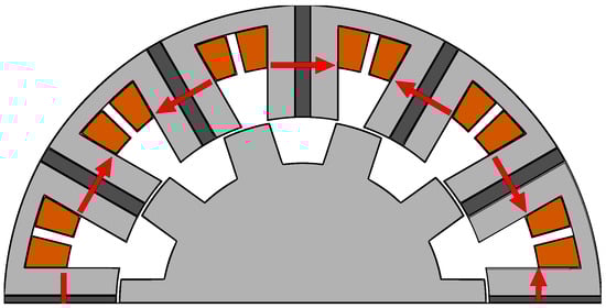
Figure 2.
Cross-section of a 12-slot, 10-rotor-tooth FSPM machine. The red arrows indicate the magnetization direction of each magnet.
- U-shaped stator laminations, with non-overlapping concentrated windings.
- Circumferentially magnetized PMs with alternate polarity, sandwiched between stator laminations.
- Rotor made of iron with a mechanically robust structure, similar to that of switched reluctance motors.
2.2. Working Principle
Both the stator and the rotor present a salient structure; bipolar flux linkage variations are produced through rotor rotation. A complete electrical period corresponds to a mechanical rotation equal to the angle between two adjacent rotor teeth; consequently, the number of pole pairs is equal to the number of rotor teeth. Concerning the torque production mechanism, it has been extensively studied in [6,7], and also an alternative perspective is given in [8]. The doubly salient structure of this motor results in a distorted air-gap flux density, compared with IPM and SPM machines; this is caused by the modulation of the magnetic field produced both by PMs and the excitation currents in stator windings. As a result, of the average torque is produced by several synchronized air-gap harmonics produced by PMs and excitation currents [4].
3. Analytical Model
In order to obtain a preliminary machine geometry definition, an analytical model has been employed, avoiding the long simulation times associated with FEM while still providing acceptable accuracy. The motor design obtained analytically has been validated through FEM and subsequently improved.
3.1. Limitations
It is important to highlight that the approach used does not include the nonlinear behavior of the iron as well as the tangential components of the air-gap flux density, making it suitable for early-stage design and preliminary dimensioning. The effect of saturation and of the tangential components is then evaluated through finite element analysis.
3.2. Requirements
In the design procedure, the specifications of the motors currently in use are taken as a reference, while assuming the same battery and inverter configuration as specified in Table 1.

Table 1.
Current Powertrain specifications.
Regarding the FSPM motor slot/pole configuration, in order to limit the excitation fundamental frequency at a given speed, configurations with a smaller number of slots and poles are preferable for high-speed applications. Only a limited number of slot/pole combinations are feasible. Although the minimum number of stator slots is six, as shown in [9], this configuration is not suitable for high-speed applications due to the resulting unbalanced back-EMF waveform, which leads to increased harmonic losses, as well as to the presence of unbalanced radial forces acting on the rotor. The next feasible slot number is twelve, with a minimum of ten rotor teeth. This configuration is the most commonly adopted for this type of machine. Although it is not the optimal one in terms of torque density—which can be improved by using alternative stator teeth and magnet configurations [10,11]—the 12/10 two-tooth layout is selected in this work for the sake of simplicity. Additionally, alternative permanent magnet configurations for outer-rotor in-wheel applications have been investigated in [12].
3.3. Model Description
Different approaches have been developed for the analytical modeling of FSPM machines, such as the nonlinear magnetic equivalent circuit model [13] or through the solution of field equations at the air gap by means of Fourier analysis [14]. The method used in this work, similarly to the one presented by B. Gaussens in [15], is based on air-gap permeance and MMF functions. Following the permeance-based analytical formulation adopted in [16], the total magnetic permanence distribution between stator and rotor can be expressed as
where is the physical air gap between the stator and the rotor; is the stator equivalent air-gap function, which can be decomposed in the winding slot and magnet slot contributions, and , respectively; is the rotor equivalent air-gap function; is the angular position in the stator reference frame; is the angular position in the rotor reference frame; and is the angular shift between the rotor reference frame and the stator reference frame. The air-gap flux density distribution can be expressed as
where and are the functions which define the magnetomotive force produced by the magnets and the winding currents
3.3.1. Stator Equivalent Air-Gap Function
The stator equivalent air-gap function is computed by considering only the effect of winding and magnet slots, thus assuming a smooth rotor. Firstly, the equivalent air-gap function , associated with winding slots, is computed, by assuming indefinitely deep slots and a simplified circular path for the leakage flux lines as in [15]. The equivalent path of the flux lines is obtained by means of two parallel paths, and , as shown in Figure 3, where the radius of these circular paths depends on the angular coordinate .
where is the stator inner diameter. Then, substituting (1) and (2) in (3), the expression becomes
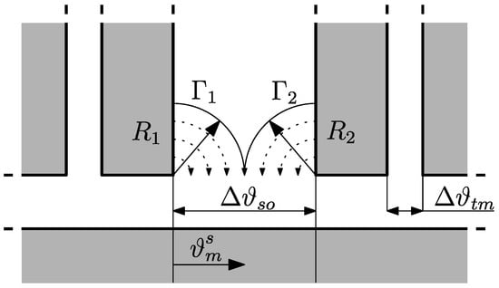
Figure 3.
Flux paths within the stator winding slot.
Figure 4 provides a graphical representation of the equivalent air-gap function due to the winding slots, which can be expressed by means of the Fourier series expansion as
where
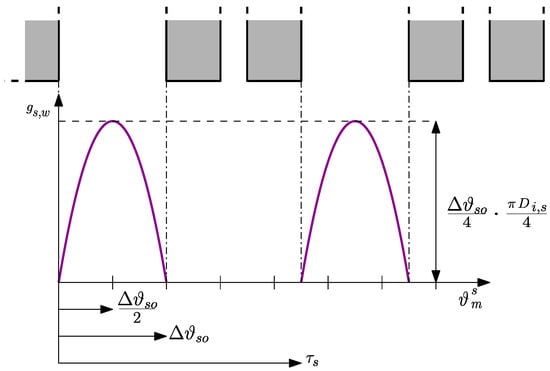
Figure 4.
Stator equivalent air-gap function associated with winding slots.
The equivalent air-gap function associated with magnet slots is obtained with the same procedure, by substituting the angle corresponding to the winding slot opening, , with the angle corresponding to the magnet slot opening, :
where
A phase shift is added to the two functions so that the magnet slots are centered on the stator teeth, and the origin of the system of reference is centered with stator teeth. Finally, the stator equivalent air-gap function is obtained as
3.3.2. Rotor Permanence Distributions
The rotor equivalent air-gap function is obtained by assuming a slotless stator, no magnet or winding slots; in this case, rotor slots correspond to the spacing between two teeth. The procedure is the same as the one for the equivalent air-gap function associated with winding slots, so it only requires the following changes:
Then, a phase shift is introduced in order to align rotor teeth with the origin of the rotor reference frame. Finally, the additional phase shift can be used to rotate the rotor in the stator reference frame. A visualization of the flux paths within the rotor teeth is provided by Figure 5, meanwhile Figure 6 shows the resulting rotor equivalent air-gap function.
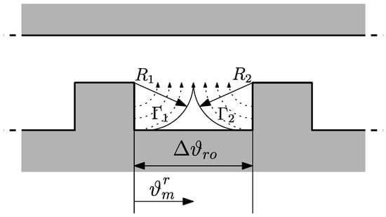
Figure 5.
Flux paths within the rotor teeth.
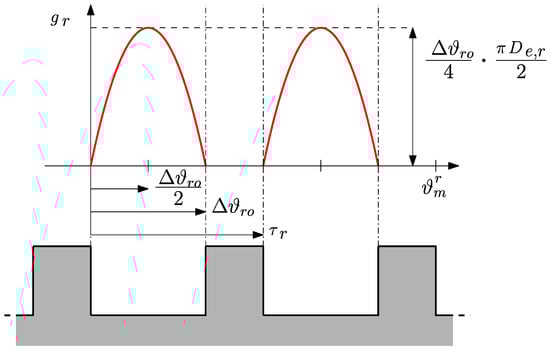
Figure 6.
Rotor equivalent air-gap function.
Finally, the stator and rotor air-gap distributions when a rotor tooth is aligned with the reference stator tooth are shown in Figure 7.
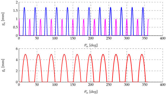
Figure 7.
Equivalent air-gap functions: stator contribution (top) and rotor contribution (bottom).
3.3.3. Magnets MMF
In order to derive the Magnetomotive Force function, associated with the excitation provided by the magnets, the no-load maximum value of the air-gap flux density produced by the PMs is computed by applying Ampere’s law and Gauss’s law, as well as the magnet characteristic equation considering the flux paths of Figure 8.
where and are the values of the magnetic field and flux density within the magnet, and are the values of the magnetic field and flux density in the air gap, is the residual flux density, and are the magnetic permeability of the void and the relative permeability of the air, is the thickness of the magnet, is the pole air-gap surface and is the magnet surface orthogonal to the flux lines:
By solving the system of equations, the magnet flux density is obtained as
Then, the air-gap flux density is
Finally, the maximum value of the magnets MMF is obtained as
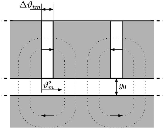
Figure 8.
Flux paths associated with the permanent magnets.
By assuming a linear variation in the MMF within the PMs, the MMF function is represented by a trapezoidal wave with a period of , as shown in Figure 9, which can be expressed by means of the Fourier series expansion as
where
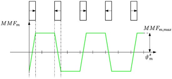
Figure 9.
Equivalent magnetomotive force distribution produced by the permanent magnets.
3.3.4. Windings MMF
Similarly to what has just been described, the magnetomotive force produced by each phase winding is represented by trapezoidal half-waves, see Figure 10, where the amplitude at a given time is
where is the amplitude of the phase x current at a given time, while is the number of series-connected conductors per slot. The MMF distribution of each phase is described by the following Fourier series expansion:
In which is the phase shift of the j-th phase:
And the series coefficients are
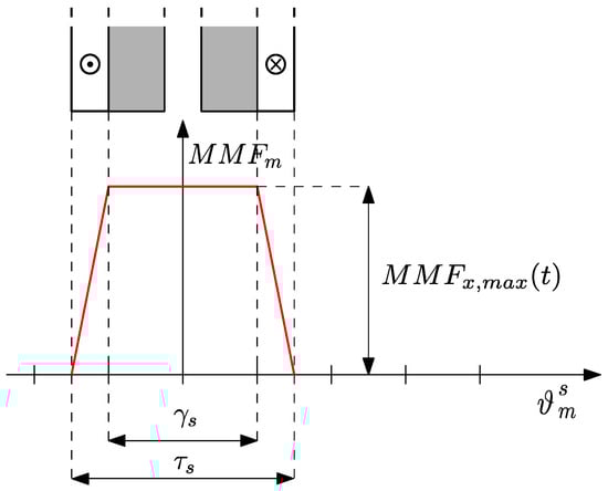
Figure 10.
Equivalent magnetomotive force distribution produced by the stator windings.
A graphical representation of the magnetomotive force distribution produced by the stator windings is given by Figure 11.
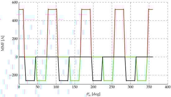
Figure 11.
MMF distributions of the three phases: phase a () in red, phase b () in green, phase c () in black.
4. Analytical and FEM Results Comparison
4.1. Geometry
The stator and rotor geometries obtained iteratively through the analytical model are reported in Table 2. These parameters were subsequently implemented in a FEM aimed at validating the results of the analytical simulations. To ensure a fair comparison with the analytical model, the nonlinear magnetic behavior of the iron is not included in this validation stage. Therefore, the comparison presented in Section 4 is performed between the analytical model and a linear FEM.
Table 2.
FSPM motor geometry.
4.2. Comparison
No-load flux and torque are evaluated over a rotor rotation corresponding to 360 electrical degrees (). As shown in Figure 12, the agreement between analytical and FEM results is generally good, although some differences are observed. These deviations are primarily due to the analytical model computing the air-gap flux density at the sampled points, based on the local values of permeance and MMF functions. As a result, only the radial component of the flux density is captured. However, as shown in the following figures, the analytical approach still allows the prediction of the machine performance with acceptable precision.
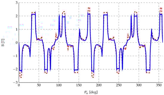
Figure 12.
Air-gap flux density: analytically computed (blue) and FEM-computed (dashed red).
The no-load flux linkage obtained with the two models is compared in Figure 13. The maximum value analytically computed is , while the value obtained through the FEM is , resulting in a relative error of .
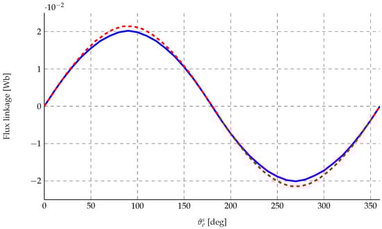
Figure 13.
No-load flux linkage: analytically computed (blue) and FEM-computed (dashed red).
The torque at nominal operating conditions has also been compared, considering a stator current of . In order to have a fair comparison between the analytical model and FEM, the torque computed using the d-q flux components is considered:
This formulation represents the average electromagnetic torque of the machine. It does not account for the oscillating (torque ripple) component because the analytical model computes the flux linkage as the sum of the flux contributions in each segment into which the air gap has been discretized. With this approach, only the average component of the air-gap flux density contributes to the torque calculation, while the spatial harmonics responsible for torque ripple are inherently neglected. Moreover, although in FSPM machines a reluctance torque component can appear under high magnetic saturation, the comparison shown in Figure 14 is carried out at the nominal current condition. Under these operating conditions, the d-axis and q-axis inductances are expected to assume similar values, resulting in a negligible reluctance torque contribution compared to the permanent magnet contribution. This assumption is further confirmed by the nonlinear FEM analysis reported in Appendix A.2. Therefore, the torque expression is simplified as
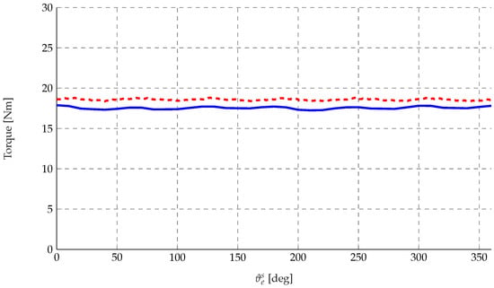
Figure 14.
Torque under constant load operation: analytically computed (blue); FEM-computed (dashed red).
The average torque computed through the FEM is , while the analytical model predicts an average value of . This leads to a relative error of , which confirms the good agreement between the two approaches. To further assess the predictive capability of the analytical model over the whole operating range, an evaluation of the torque error over the dq-plane has been carried out. The resulting error distribution is reported in Appendix A.1.
5. Design Improvement and Validation
5.1. Magnet Slot Design
In the design refinement and performance evaluation stage, a nonlinear FEM is adopted in order to account for magnetic saturation effects. This nonlinear model is used in all the analyses presented in this section. A proper slot–magnet design is essential to ensure the manufacturability of the prototype. During the curing process, the laminations must remain precisely aligned so that the magnets can be correctly inserted into the slots afterward. In addition, the laminations must provide sufficient structural integrity to allow safe handling during assembly, without the risk of deformation.
To guarantee adequate mechanical robustness, a 1 mm magnetic bridge is introduced on top of each magnet slot. Although this solution leads to a limited amount of flux leakage, the resulting increase in back-iron thickness reduces magnetic saturation in the machine. As a consequence, the diameter is increased to 125 mm and the overall torque output remains essentially unchanged, see Figure 15.

Figure 15.
Magnet slot before (right) and after (left) manufacturing-oriented design improvement.
Furthermore, to ensure proper alignment of the laminations during assembly, four notches with a radius of 1 mm are introduced along the outer diameter of the machine.
5.2. Magnet Design: Eddy-Current Mitigation and Demagnetization Analysis
5.2.1. Eddy-Current Mitigation
Unlike conventional machine configurations, in which the permanent magnets are located on the rotor and experience flux variations mainly due to the slotting effect, stator-mounted magnet topologies exhibit significantly larger flux fluctuations. In Flux-Switching Permanent Magnet (FSPM) motors, the magnets are fully subjected to the time-varying magnetic field produced by the stator currents flowing in the concentrated windings around the teeth. These pronounced flux variations induce substantial eddy currents within the magnets, see Figure 16, leading to increased magnet losses, excessive heating, and a consequent degradation of machine performance. For this reason, the use of specially laminated or segmented permanent magnets is of considerable importance in FSPM machines, as it effectively limits eddy-current circulation and significantly reduces associated losses.
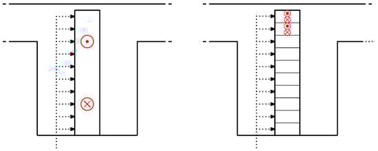
Figure 16.
Schematic comparison between non-laminated and laminated magnets: eddy-current mitigation.
Consequently, a 10-layer laminated magnet is adopted for this machine. As shown in Figure 17 and Figure 18, this solution results in a dramatic reduction in magnet losses.
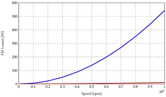
Figure 17.
Direct comparison of permanent magnet losses as a function of rotational speed between non-laminated magnets (blue) and laminated magnets (red).
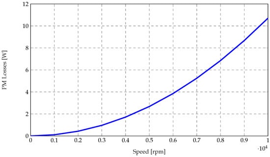
Figure 18.
Focus on laminated permanent magnet losses as a function of rotational speed.
5.2.2. Demagnetization Analysis
The resistance of the magnets to demagnetization was evaluated by applying increasing direct-axis (d-axis) demagnetizing currents. The applied current ranged from 0 up to twice the peak current delivered by the inverter.
As shown in Figure 19, the average flux density in the magnets remains positive throughout the entire current range. Considering that the B–H characteristic of N45UH magnets exhibits a knee point—beyond which irreversible demagnetization occurs at 120 °C for negative flux densities—the magnets are effectively protected under the tested conditions.
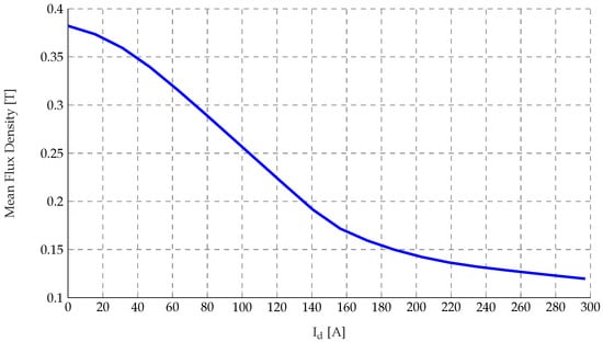
Figure 19.
Average flux density in the magnets as a function of applied direct-axis current.
5.3. Rotor Geometry Improvement
The rotor geometry was optimized by selectively removing iron from magnetically inactive regions, as shown in Figure 20. This design refinement allowed a reduction in the rotor mass by approximately 270 .
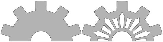
Figure 20.
Rotor geometry before iron mass reduction (left); rotor geometry after iron mass reduction (right).
However, the resulting lightweight structure introduces areas where the cross-sectional thickness (in the plane) is significantly reduced. Considering the high rotational speed of the machine, a mechanical stress analysis becomes necessary to verify the structural integrity of the rotor and to ensure safe operation under centrifugal loading. The results shown in Figure 21 indicate that the maximum stress at 20 remains well below the material yield strength reported in the datasheet ( 260 ).
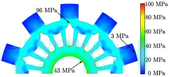
Figure 21.
Stress distribution within the rotor.
An additional performance improvement is achieved through the adoption of a six-step skewing of the rotor laminations.
Once the electromagnetic and mechanical design of the machine is finalized, the total mass of the active parts is evaluated. Table 3 reports the mass breakdown of the stator iron, rotor iron, copper windings, and permanent magnets, together with the resulting total active mass of the machine. Although the stator diameter has been increased to enhance manufacturability, the overall weight of the machine’s active components remains well within the typical range for machines employed in this type of application.
Table 3.
FSPM motor active mass contributions.
5.4. Performance Evaluation
Figure 22 reports the FEM-derived torque and power versus speed characteristics under both overload and nominal operating conditions (dashed).
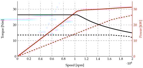
Figure 22.
Torque (black) and power (red) versus speed: continuous lines indicate overload; dashed lines indicate nominal operation.
For the overload condition,
- Continuous torque: .
- Base speed: .
- Maximum power: .
For nominal load operation,
- Continuous torque: .
- Base speed: .
- Maximum power: .
The machine demonstrates strong torque and power performance, with overload operation enabling higher torque at reduced speed and peak power suitable for the dynamic demands of Formula Student racing.
6. Manufacturing Aspects
6.1. Iron Laminations
The laminations used in the prototype are coated with a backlack insulation layer, which enables the stack to be bonded through thermal curing without the need for welding or soldering. This process ensures that the laminations remain fully electrically insulated from each other. However, the adoption of this solution requires special care during manufacturing, particularly to ensure proper alignment of the iron laminations throughout the thermal curing process. For the rotor, this issue is solved by curing the laminations while they are already stacked onto the shaft. In the stator, lamination alignment is finally achieved by inserting 12 mm pins into the slots instead of using notches on the outer diameter, as this provides greater structural solidity. High-temperature-resistant insulating spacers, similar to those commonly used in transformer winding manufacturing, are also inserted to preserve the magnet slot geometry during the curing process.
The stator and rotor stacks were subsequently compressed, resulting in the core packs shown in Figure 23. A torque wrench was used to ensure the uniform application of the pressure required for the proper activation of the backlack coating. This step was essential to guarantee intimate contact between adjacent laminations during the bonding process and to promote consistent adhesion across the entire stack height.
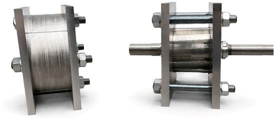
Figure 23.
Lamination- pressed packs before curing process.
The curing process was performed in a controlled oven environment, starting from an ambient temperature of 30 °C. The thermal cycle was defined to ensure complete polymerization of the coating while avoiding thermal stresses that could compromise stack alignment. The procedure was carried out according to the following sequence:
- Temperature ramp: 19 min at a controlled heating rate of 10 .
- Dwelling phase: 30 for the rotor stack and 40 for the stator stack, in order to ensure full curing of the adhesive layer.
- In-oven cooling: 30 for the rotor and 50 for the stator stack, allowing gradual temperature reduction under controlled conditions.
- Open-air cooling until ambient temperature was reached.
The results of the curing process is shown in Figure 24.
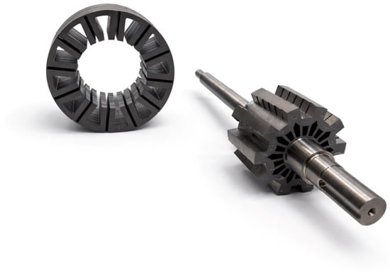
Figure 24.
Curing process results.
After the curing process, the permanent magnets are inserted into the stator slots and fixed using structural adhesive, see Figure 25.
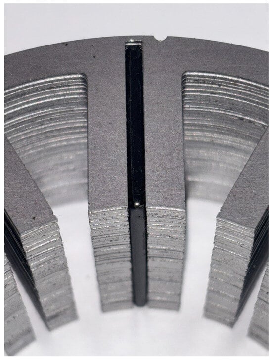
Figure 25.
Magnet insertion into the stator core.
6.2. Stator Windings
Since the manufactured prototype is intended for laboratory investigations and experimental analysis, not all tooth coils belonging to each phase have been permanently connected by soldering. Some coil connections have intentionally been left open, as shown in Figure 26, in order to allow the implementation of a six-phase asymmetrical winding configuration, enabling further studies on multiphase applications.
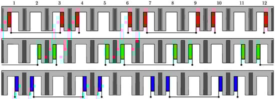
Figure 26.
Stator winding connections.
During the winding manufacturing process, the stator stack was fixed on a dedicated support. Each coil was then inserted individually; to simplify the procedure, the coils were wound in an alternating sequence. Once the insertion process was completed, see Figure 27, the fixed connections between coils were soldered and insulated. Meanwhile, the phase terminals were connected to external cables with an equivalent cross-sectional area.
Figure 27.
Stator winding process results.
6.3. Design Improvement Summary
Table 4 summarizes the design changes proposed based on the considerations in Section 5, along with their corresponding effects on the machine performance and manufacturability.
Table 4.
Design features and corresponding effects.
7. Conclusions and Future Developments
This paper has presented the design, analysis, and prototyping of a Flux-Switching Permanent Magnet (FSPM) motor specifically developed for Formula SAE electric vehicle applications. An analytical modeling approach based on air-gap permeance and magnetomotive force distributions was employed as a preliminary design tool, enabling a rapid definition of the main geometrical parameters while significantly reducing computational effort compared to full finite element simulations.
The analytical results were validated through finite element analysis, showing good agreement in terms of air-gap flux density, no-load flux linkage, and electromagnetic torque, with relative errors consistently below . This confirms the suitability of the proposed analytical model for early-stage FSPM motor design. Based on the validated model, several design refinements were introduced to improve manufacturability, mechanical robustness, and electromagnetic performance, including optimized magnet slot geometry, laminated permanent magnets for eddy-current loss mitigation, and a lightweight rotor design verified through mechanical stress analysis.
The machine achieves torque and power levels that are compatible with the electromagnetic performance requirements typically encountered in Formula SAE, while maintaining a compact structure and a low active mass. However, complete validation would require detailed loss and thermal analyses.
Future work will focus on extensive experimental testing of the manufactured prototype to validate the predicted performance under real operating conditions. In addition, the intentionally flexible stator winding connections will enable further investigations into six-phase asymmetrical winding configurations, fault-tolerant control strategies, and advanced multiphase drive solutions, with the aim of further enhancing reliability and performance in high-demand motorsport and automotive applications.
Author Contributions
Conceptualization: F.C.; investigation: F.C.; methodology: F.C.; writing—original draft: F.C.; writing—review and editing: N.B., F.C.; supervision: N.B. All authors have read and agreed to the published version of the manuscript.
Funding
This research received no external funding.
Data Availability Statement
The original contributions presented in this study are included in the article. Further inquiries can be directed to the corresponding author.
Conflicts of Interest
The authors declare no conflicts of interest.
Appendix A
Appendix A.1
To evaluate the analytical model accuracy over the operating region, the electromagnetic torque error has been computed across the dq current plane. The comparison is performed between the analytical model and the linear FEM.
The resulting error distribution is shown in Figure A1. The Maximum Torque per Ampere (MTPA) and Maximum Torque per Voltage (MTPV) trajectories are also indicated to highlight the machine operating region.
The analytical model maintains good agreement with the FEM results over the operating region of interest, with the largest discrepancies occurring in the deep flux-weakening region (≈11.3%).
Finally, it should be noted that a small difference with respect to the error specified in Section 4.2 is present, since in the mapping procedure for this diagram, the rotor is kept still while the stator currents are changed; meanwhile, the error reported in Figure 14 refers to the average torque values from a full rotation.

Figure A1.
Analytical model error compared to linear FEM.
Figure A1.
Analytical model error compared to linear FEM.

Appendix A.2
To clarify the contribution of reluctance torque, the direct-axis and quadrature-axis inductances have been evaluated over the current plane using the nonlinear FEM.
Figure A2 and Figure A3 show the distributions of and , respectively, while Figure A4 reports the percentage difference between the two inductances.

Figure A2.
Nonlinear FEM map over the current plane.
Figure A2.
Nonlinear FEM map over the current plane.


Figure A3.
Nonlinear FEM map over the current plane.
Figure A3.
Nonlinear FEM map over the current plane.


Figure A4.
Percentage difference between and over the current plane obtained from nonlinear FEM simulations.
Figure A4.
Percentage difference between and over the current plane obtained from nonlinear FEM simulations.

The inductance behavior over the domain results in non-negligible reluctance torque values for high-load working points; see Figure A5. However under nominal current condition (), the reluctance torque component is inherently very small, and the electromagnetic torque is therefore mainly determined by the permanent magnet contribution.

Figure A5.
Reluctance torque mapping over the dq-plane.
Figure A5.
Reluctance torque mapping over the dq-plane.

References
- Wang, P.; Hua, W.; Zhang, G.; Wang, B.; Cheng, M. Principle of Flux-Switching Permanent Magnet Machine by Magnetic Field Modulation Theory—Part I: Back-Electromotive-Force Generation. IEEE Trans. Ind. Electron. 2022, 69, 2370–2379. [Google Scholar] [CrossRef]
- Liu, C.; Xu, D.; Wu, W.; Yang, B. The Study of the Salient Pole Geometry Optimization of the Flux Switching Permanent Magnet Machine. Actuators 2024, 13, 398. [Google Scholar] [CrossRef]
- Sarshar, M.R.; Jalali Kondelaji, M.A.; Asef, P.; Mirsalim, M. Electromagnetic Investigation of Innovative Stator–Permanent Magnet Motors. Energies 2025, 18, 2400. [Google Scholar] [CrossRef]
- Chen, H.; El-Refaie, A.M.; Demerdash, N.A.O. Flux-Switching Permanent Magnet Machines: A Review of Opportunities and Challenges—Part I: Fundamentals and Topologies. IEEE Trans. Energy Convers. 2020, 35, 684–698. [Google Scholar] [CrossRef]
- Wang, Q.; Zhao, X.; Niu, S. Flux-Modulated Permanent Magnet Machines: Challenges and Opportunities. World Electr. Veh. J. 2021, 12, 13. [Google Scholar] [CrossRef]
- McFarland, J.D.; Jahns, T.M.; El-Refaie, A.M. Analysis of the Torque Production Mechanism for Flux-Switching Permanent-Magnet Machines. IEEE Trans. Ind. Appl. 2015, 51, 3041–3049. [Google Scholar] [CrossRef]
- Zhu, Z.Q.; Liu, Y. Analysis of Air-Gap Field Modulation and Magnetic Gearing Effect in Fractional-Slot Concentrated-Winding Permanent-Magnet Synchronous Machines. IEEE Trans. Ind. Electron. 2018, 65, 3688–3698. [Google Scholar] [CrossRef]
- Wang, P.; Hua, W.; Zhang, G.; Wang, B.; Cheng, M. Principle of Flux-Switching PM Machine by Magnetic Field Modulation Theory—Part II: Electromagnetic Torque Generation. IEEE Trans. Ind. Electron. 2022, 69, 2437–2446. [Google Scholar] [CrossRef]
- Li, Y.; Li, S.; Yang, Y.; Sarlioglu, B. Analysis of Flux-Switching Permanent Magnet Machine Design for High-Speed Applications. In Proceedings of the IEEE Energy Conversion Conference and Expo (ECCE), Pittsburgh, PA, USA, 14–18 September 2014; pp. 302–309. [Google Scholar] [CrossRef]
- Chen, J.T.; Zhu, Z.Q.; Howe, D. Stator and Rotor Pole Combinations for Multi-Tooth Flux-Switching Permanent-Magnet Brushless AC Machines. IEEE Trans. Magn. 2008, 44, 4659–4667. [Google Scholar] [CrossRef]
- Yang, H.; Li, Y.; Lin, H.; Zhu, Z.Q.; Lyu, S. Principle Investigation and Performance Comparison of Consequent-Pole Switched Flux PM Machines. IEEE Trans. Transp. Electrif. 2021, 7, 766–778. [Google Scholar] [CrossRef]
- Bi, Y.; Fu, W.; Niu, S.; Huang, J. Comparative Analysis of Consequent-Pole Flux-Switching Machines with Different Permanent Magnet Arrangements for Outer-Rotor In-Wheel Direct-Drive Applications. Energies 2023, 16, 6650. [Google Scholar] [CrossRef]
- Zhu, Z.Q.; Pang, Y.; Howe, D.; Iwasaki, S.; Deodhar, R.; Pride, A. Analysis of Electromagnetic Performance of Flux-Switching Permanent-Magnet Machines by Nonlinear Adaptive Lumped Parameter Magnetic Circuit Model. IEEE Trans. Magn. 2005, 41, 4277–4287. [Google Scholar] [CrossRef]
- Gysen, B.L.J.; Ilhan, E.; Meessen, K.J.; Paulides, J.J.H.; Lomonova, E.A. Modeling of Flux Switching Permanent Magnet Machines With Fourier Analysis. IEEE Trans. Magn. 2010, 46, 1499–1502. [Google Scholar] [CrossRef]
- Gaussens, B.; Hoang, E.; de la Barriere, O.; Saint-Michel, J.; Lecrivain, M.; Gabsi, M. Analytical Approach for Air-Gap Modeling of Field-Excited Flux-Switching Machine: No-Load Operation. IEEE Trans. Magn. 2012, 48, 2505–2517. [Google Scholar] [CrossRef]
- Bianchi, N. Analysis and Design Remarks of Variable Flux Reluctance Motors. In Proceedings of the IEEE Workshop Electrical Machines Design, Control and Diagnosis (WEMDCD), Valletta, Malta, 9–10 April 2025; pp. 1–6. [Google Scholar] [CrossRef]


Disclaimer/Publisher’s Note: The statements, opinions and data contained in all publications are solely those of the individual author(s) and contributor(s) and not of MDPI and/or the editor(s). MDPI and/or the editor(s) disclaim responsibility for any injury to people or property resulting from any ideas, methods, instructions or products referred to in the content. |
© 2026 by the authors. Licensee MDPI, Basel, Switzerland. This article is an open access article distributed under the terms and conditions of the Creative Commons Attribution (CC BY) license.