Abstract
This paper studies the progressive damage process and final damage form of composite laminate aircraft radome under high-speed hail impact A simulation method based on Peridynamic bond-based theory is proposed to study the progressive damage process and final damage form of composite laminate aircraft radome under high-speed hail impact. Using the Peridynamic theory, the dynamic damage behavior of hailstone impact on a composite laminate plate is analyzed, and an impact model of hailstone impact is established to study the damage initiation, expansion, and failure behavior of the composite laminate. The dynamic mechanical constitutive and failure criteria that characterize the macromechanical behavior of both hailstone and composite laminate during impact are established. Additionally, equations describing the interaction forces between these two materials are proposed to develop a numerical simulation method for the laminate failure process. The dynamic damage evolution and failure mechanisms are subsequently investigated to provide a theoretical foundation for the optimum design of composite structures, such as aircraft radomes, subjected to hail impact. To describe the interaction force equations between two materials, a new method based on Peridynamics (PD) is proposed to establish a numerical simulation method for the damage process of laminated plates. This method provides a theoretical basis for optimizing the design of composite structures (such as aircraft radome) after being impacted by hail.
1. Introduction
In comparison to single materials, composite materials offer significant advantages such as light weight, high strength, and superior design flexibility [1,2,3]. As a result, they are widely used in engineering structures, especially in the aerospace field, where they constitute over half of the mass of materials manufactured for large airliners like the Airbus A350 in Europe and Boeing B787 in the United States [4]. In service, composite structures such as flight control surfaces, wings, body skins, and radomes are often subjected to damage from high-speed hail impacts [5,6]. In 2018, a passenger plane in Tianjin encountered hail during flight, resulting in cracks to the outer layers of both the left and right windscreens and damage to the radome. In 2019, an airliner flying from Guangzhou to Beijing was hit by hail in the air, damaging its radar cover and windscreen, which prompted the flight crew to declare an emergency. Thus, to improve the design and ensure the safety of aircraft radomes, it is important to study the dynamic damage behavior of composite structures under hail impact. Given the high cost of high-speed impact testing equipment and the complexity of such experiments, numerical simulation of hail impact on composite laminated panels is particularly important.
The study of the damage and failure mechanisms in solid materials remains a significant focus within mechanical research. For static and quasi-static behaviors of composite material, experimental results obtained using traditional mechanical methods closely align with the numerical results [7,8,9]. However, simulating the progressive damage process of a composite structure under high-speed hail impact involves a series of discontinuous problems, including the initiation and development of cracks in the laminated structure and interlaminar slip [10], as well as the fragmentation of hailstones during the impact process. As a result, the traditional numerical results method cannot accurately simulate the large-scale deformation during the hail impact process or the discontinuous displacements generated. The Peridynamic method is highly suitable for solving these problems [11,12,13,14].
In recent years, scholars have begun to apply the PD theory to the study of damage fields in composite materials. Hu et al. [15,16], based on PD matrix theory, proposed a progressive damage model for composite laminates to analyze three types of damage: fiber fracture, matrix fracture, and delamination damage. Yang [17] successfully used the PD method to simulate the progressive damage process of laminates under impact loading and planar velocity boundary conditions. Guo et al. [18] summarized the theoretical progress and numerical simulation methods employing the PD theory to study the failure of composite materials in recent years and introduced the mainstream PD model currently applied to composite failure. Silling [19] proposed a prototype microelastic brittle (PMB) model for simulating the mechanical behavior of various brittle materials. Wang characterized the crack location by field variables to realize the effect of the crack on the physical field of the numerical model [20]. The collective efforts of numerous researchers have led to the development of a PMB-based PD model for composite laminates, enabling effective simulation of their damage and fracture behaviors [21,22].
In damage and fracture models, the type of impact source determines how the impact contact is handled. These sources can be non-deformable objects, such as bullets, or deformable objects, such as birds or hail. Silling [23] used two technical solutions in the EMU program to address these different contact problems. For non-deformable impactors, the interaction between the impactor and impacted material can be represented by repositioning the intruding particles within the impactor [24,25]. In contrast, for deformable impactors, the contact surface is redefined through an assessment of repulsive forces between the contacting objects.
Wang et al. [26] proposed a new three-dimensional conjugate bond pye-cycle dynamic model to simulate crack initiation and propagation in brittle solids. The interaction force between two particles within an event horizon is influenced not only by bond stretching but also by the rotation of the conjugate bond angle; therefore, it overcomes the limitations imposed by a fixed Poisson’s ratio in conventional bond cycle dynamics. The classification of fracture types—the Type I (open) and Type II/III (in-plane shear/tear)—is determined by the critical tensile and critical shear energy densities of the bond, respectively. An improved explicit time integral format is proposed for investigating dynamic as well as quasi-static/static problems.
The PD method is based on the idea of non-local action integration and does not require spatial derivatives. Therefore, it has inherent advantages in accuracy when simulating complex problems with spontaneous discontinuities such as fractures and damage. It can naturally describe the initiation and propagation path of cracks, without relying on pre-defined crack paths or complex mesh techniques such as finite element method; In terms of computational efficiency, although the near-field dynamics method may require larger single point calculations when dealing with the above problems, as a meshless simulation method, it effectively avoids the computational interruption and tedious re meshing process caused by mesh deformation in the finite element method. Therefore, it usually solves the overall calculation process of the entire fault process more effectively.
In this study, the microscopic structure of the radome structure are simplified to a composite laminate plate, and a PD model is developed to represent the interaction between the hailstone and the plate. An equation is proposed to quantify the interaction force between these two different materials, facilitating an evaluation of the damage evolution law and dynamic mechanical properties of the laminate by numerical analysis. Additionally, the failure mechanisms and factors influencing damage in composite laminates subjected to high-speed hail impact are elucidated, providing a theoretical foundation for optimizing the designs of composite structures such as aircraft radomes.
2. Fundamental Principles of the Bond-Based PD Model
The PD theory describes forces by defining non-local interaction between the point pairs within a material and represents the deformation of these material points using spatial integrals rather than differential equations [27,28]. As an innovative non-local solid mechanics theory, PD can effectively simulate the physical and mechanical behaviors of solid materials at different scales, which is particularly important for evaluating the instability of large-scale deformation in inhomogeneous material structures, simulating the kinetics of crystal phase transitions, and evaluating the damage of nanomaterials [29,30]. Furthermore, PD not only provides extremely high solution accuracy but also significantly improves computational efficiency, making it more advantageous than traditional finite element methods [31,32].
In accordance with bond-based PD theory, the motion equation for any material point can be expressed as
where represents the mass density; and denote the displacement vector and acceleration vector, respectively, of material point ; signifies the horizon of material point ; represents the specified physical density field at the current moment; and represent the material point and its displacement vector at any point on the horizon of material point ; volume element corresponds to that of material point ; and the response function is defined as a pairwise force density function, representing the force vector per unit volume squared exerted by material point on material point at , which can be expressed as
where and represent the relative distance and relative displacement, respectively, between material points and ; is the bond stretch; and c is the material micro-modulus, which can be determined from the bulk modulus , shear modulus , and the horizon as follows:
Delta (): The term ‘delta’ (commonly denoted by ) is typically used interchangeably with the concept of horizon, representing the finite distance within which interactions between material points occur. In the context of Peridynamics, serves as a critical parameter that defines the size of the interaction neighborhood.
Therefore, the bond force can be represented by a history-dependent scalar value function, denoted as , specifically expressed as
where is the extreme or critical elongation for a given bond, beyond which the deformed body begins to fail. Its expression is as follows:
where is the critical energy release rate. The capability to facilitate failure at the bond level is one of the advantages of PD, as it results in a clear local damage measure at material point , defined as
3. Construction of PD Hailstone Model
In engineering practice, secondary factors associated with ice—such as shear strength, creep, and fatigue properties—are generally ignored; instead, only the mechanical properties that significantly influence engineering applications are considered. These include compressive strength, tensile strength, modulus of elasticity, and thermal properties are included. In this study, the material parameters for hailstone ice are specified as presented in Table 1.

Table 1.
Material parameters of hailstone ice.
3.1. Ductile–Brittle Transition Model
Hail impact is different from general hard object impact, mainly due to the brittle–ductile transition phenomenon of hail under high strain rate conditions and the transformation from solid to liquid under high pressure. Therefore, it is not possible to simply use general elastoplastic models to simulate hail, and it is necessary to fully consider the changes in the mechanical properties of ice hail during high-speed impact. Xiong Weipeng [33] used a bond-based PD model to fully reproduce the crack propagation details of sphere failure during hail impact.
As ice is subjected to compression, it experiences a transition from ductile to brittle behavior when the material strain rate exceeds the ductile–brittle transition limit. This property of ice is critical in the field of ice protection engineering, as it influences both the compressive strength of ice and, consequently, the impact load on the ice protective structures. Therefore, to accurately simulate the mechanical properties of hailstone ice, this study establishes a ductile–brittle transition model grounded in PD theory. However, since there is no concept of stress or strain in PD theory, it is not possible to directly extract the strain rate as a control variable for transitioning from ductile to brittle material models. In the PD theory, bond elongation is similar to classical mechanics’ strain and is also used to measure the degree of material deformation. Therefore, this study uses the time derivative of bond elongation as the control variable for the material model transition. The rate of change in bond length is as follows:
After determining , the corresponding transition of the force density function model can be controlled. When is less than a certain value, the force density function acts according to a ductile model; when reaches or exceeds this value, the force density function acts according to the brittle model. In this study, the value of which the ductile–brittle transition occurs is designated as the ductile–brittle transition point . Hailstone ice is considered ductile when and brittle when .
The PD force density function applied to the hailstone in this study includes the following typical mechanical properties of ice: (1) ductile–brittle behavior under fast compressive loading; (2) ductile behavior under slow compressive loading; (3) ductile–brittle behavior under tensile loading at any rate; and (4) different tensile and compressive strengths. The force density function for hailstone ice is shown in Figure 1.
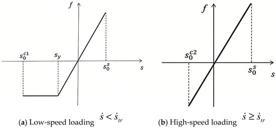
Figure 1.
Force density function of hailstone ice material model using PD theory.
Indeed, ice exhibits different mechanical properties under tensile and compressive loads. In this study, positive and negative bond elongations are used to differentiate between tensile and compressive loading; specifically, when the bonds between material points are subjected to compression, , whereas when they are subjected to tension, . Furthermore, ice exhibits varying ductile–brittle transitions under compressive loading at different rates. As illustrated in Figure 1, the bond under tensile loading exhibits brittle behavior. The PD parameters of the hailstone model are established based on this approach, as shown in Table 2.
Table 2.
PD hailstone model parameters.
3.2. Short-Range Forces for Large-Scale Deformation
At present, the established PD model considers only the bonding force between material points, which is a nonlocal force. During impact, hailstones undergo large-scale deformation, resulting in some material points completely losing their bonding force and becoming free particles. This phenomenon may lead to local non-physical penetration of the hailstone within the model, which is not inconsistent with the actual situation. To address this issue, a short-range force model is introduced to solve the problem under the condition that the hailstone material points are completely disconnected as follows:
where is the small distance between material points and ; and denote the vertical coordinates of the hailstone material points before and after deformation, respectively; is the horizon; and .
The acting distance of the short-range force is expressed as
where represents the initial distance between material points and ; and are the cross coordinates of hailstone material points before and after deformation, respectively; and is the volume modulus.
4. Construction of PD Composite Laminate Model
4.1. Modeling of Composite Laminate
In order to simulate the anisotropy of FRP laminates and correct the influence of bond-specific Poisson’s ratio, the fiber direction, thickness direction, and other bond directions need to be distinguished. Material points are connected to other material points in their near-field domain through various types of bonds, and four bond types are introduced to describe the interactions between material points within a single-layer plate and between material points in a laminated plate [34]. The interaction between two material points along the fiber direction inside a single-layer board is described using fiber bonds; The interaction between two material points in other directions inside a single-layer board is described using matrix bonds; The normal force between two material points along the thickness direction between plates is described using interlayer normal bonds; The shear force between two material points between plates is described using interlayer shear bonds. Fiber bonds and matrix bonds are used together to describe the in-plane properties of laminates; The interlayer normal bond and interlayer shear bond are used together to describe the interlayer properties of laminated boards.
In consideration of the composite laminate manufacturing process, the model employed in this study assumed that bonds within a single layer plane with angles less than 10° are classified as fiber bonds, while bonds with angles greater than 10° are designated as matrix bonds, and the matrix bond constant varies with the angle between the bonds and the fiber direction [35]. Due to the inherent characteristics of the PD model, shorter bond lengths exert a more significant effect on material points. Under tensile load, when the elongation of the fiber and matrix bonds in the monolayer reaches the critical elongation, it is assumed that they are immediately destroyed, resulting in a complete loss of load-bearing capacity. Under compressive load, the fiber bonds are immediately destroyed upon reaching the critical elongation, resulting in a complete loss of their bearing capacity; however, although the matrix bonds are also considered to be destroyed to some extent, they are assumed to still support half of the applied load at yield. At this point, it is considered that bond failure has occurred and that this process is irreversible. A separate laminate model consisting of interlaminar normal and shear bonds is used to capture the behavior of matrix bonds between layers in the composite laminate. The performance of these bonds is independent of the included angle. The behavior of the interlaminar normal bonds is similar to that of the matrix bond: under tensile load, when the elongation of the interlaminar normal bonds exceeded the critical elongation, they are immediately destroyed and completely lost their effectiveness; conversely, when the interlaminar normal bonds exceeded the critical elongation under compressive loading, they experience partial failure but continue to support half of the applied load at yield. The interlaminar shear bonds are assumed to behave similarly to that of the fiber bonds: they are completely destroyed, resulting in a loss of load-bearing capacity, when the angle between layers exceeds the critical shear angle. Figure 2 shows the change in bond force with elongation for each bond type considered in this model.
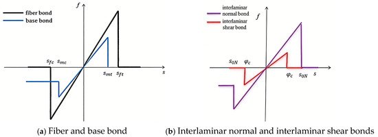
Figure 2.
Variation in bond force with elongation .
In Figure 2, and represent the critical elongations of the fiber bonds under tension and compression, respectively; and denote the critical elongations of matrix bonds under tension and compression, respectively; indicates the critical elongation of the interlaminar normal bond, while signifies the critical shear angle of the interlaminar shear bond.
In this study, the critical elongation parameters of in-plane bonds are solved using the method proposed by Hu, which is described as follows for fiber bonds:
For matrix bonds, it is described as follows:
where and denote the tensile and compressive strengths of the composite in the fiber direction, respectively, while and represent the tensile and compressive strengths of the composite perpendicular to the fiber direction, respectively.
The matrix bonds govern the material properties in all directions within the plane of a single layer and exhibit isotropic behavior; therefore, the critical elongation of the matrix bonds can be expressed as that of an isotropic material in a two-dimensional plane. The fiber bonds play a crucial role in determining the material properties along the direction of fiber reinforcement, and their critical elongation is contingent upon the fracture energy required for fiber breakage. The critical deformation of the interlaminar normal and interlaminar shear bonds between layers can be determined by the interlaminar energy release rate. The critical elongation of the interlaminar normal bonds and the critical shear angle of the interlaminar shear bonds can be obtained by breaking these bonds at the material points between adjacent layers, calculating the requisite energy for this process, and equating it to the energy release rate associated with the corresponding type of crack as follows:
Here is the plate thickness, denotes the interlaminar modulus of elasticity, and represents the interlaminar shear mode. It is generally acknowledged that and are considered in actual calculations. represents Longitudinal elastic modulus, while denotes the Transverse elastic modulus. refers to the energy release rate for type I cracks, indicates the shear modulus parallel to the fiber surface, and signifies the shear modulus perpendicular to the fiber surface.
The CCF300/10128H composite material is selected as the laminate material for this study due to its prevalent use in aircraft radomes, with its performance parameters listed in Table 3.
Table 3.
Performance parameters of CCF300/10128H composite sheet.
The micro parameters in PD theory are determined according to G1, G2, S1, and S2, as presented in Table 3.
4.2. Impact Theory for Deformable Impactors
The impact of a hailstone on a composite laminate represents a problem involving deformable impactors. In this study, both the hailstone model and composite laminate model are controlled by the PD motion equation. From the perspective of continuum mechanics, point overlap among matter, which may arise in PD applications, is deemed unacceptable. To prevent two or more points of matter from occupying the same spatial location, a short-range force is established between the hailstone and composite laminate, as discussed in this section.
During the impact of deformable materials, when the distance between two objects is reduced to a critical value, they must be rendered mutually exclusive to accurately define the contact surface between them. Silling accordingly defined a short-range repulsion force between two points of matter as follows:
where y(j) and y(k) are the respective locations of a point of matter in the impactor and a point of matter in the impacted material, is the interaction short-range force constant, and is the critical distance.
However, the aforementioned model exclusively considers interactions between identical materials; as of now, there exists no established computational method for determining the short-range force constants and critical distances pertinent to points within two different materials. In this study, a series bond force function is employed to simulate the impact between points in deformable impactors composed of different materials. This approach ensures that the magnitude of the impact force is contingent upon the properties of both materials. Consequently, a framework for calculating short-range force constants and critical distances relevant to various materials under impact has been established as follows. As depicted in Figure 3, it is assumed that the short-range force bond between two points of matter with differing material properties constitutes a combined series bond [36]. Bonds A and B represent the respective connections within materials MA and MB.
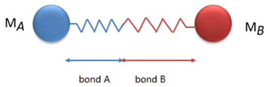
Figure 3.
Series bond model between two materials.
The initial length of bond A is defined as , with an elongation after deformation represented by ; the initial length of bond B is defined as , and its elongation of bond B after deformation is indicated by . The initial length of the series bond formed by bonds A and B has a total elongation after deformation. When the structure reaches static equilibrium after deformation, the internal forces in bonds A and B are equal. Then, represents the integral bond constant of the combined series bond, and the following formula holds:
From the relationship in Equation (17) and the elongation definitions , , and (where represents the elongation of the corresponding bond).
Let and , then Equation (18) can be reduced to
In this PD calculation model, is established to integrate the two materials into a cohesive computational framework. Therefore, , along with the parameters and between the two materials, and can be expressed as follows:
where is an engineering constant determined by the physical properties and surface morphologies of the two materials; a value of is established for the hailstone impact on the composite laminate considered in this study.
5. Impact Process Simulation
Due to the substantial costs associated with high-speed impact testing devices and intricate experimental procedures involved, it is essential to conduct numerical simulations of hailstone impacts on composite laminates. In this study, the numerical modeling is conducted with the hailstone diameter set to 0.015 m, and its material parameters are defined as listed in Table 2. The initial impact speed of the hailstone is set to 100 m/s. The geometrical dimensions of the composite laminate plate are 101 × 101 × 8 mm, with boundary conditions fixed on all sides, and its material parameters are detailed in Table 3. The thickness of a single layer in the laminate plate is 1 mm, and the layup sequence is taken as a symmetric orthogonal ply arrangement [0/90]2S. In this notation, the number indicates the order of fiber directions within each layer, the subscript ‘2’ indicates the repetition of this layer order (i.e., two sets of two layers), and the subscript ‘S’ signifies a reverse layering arrangement, resulting in the addition of four layers and yielding a total of eight layers.
In order to integrate the PD hailstone model and PD composite laminate model into a cohesive computational framework, the material point bond length , material point volume , and horizon are uniformly set in both models. The initial distance between the hailstone and composite laminate plate is set to . The calculation time step is set to in order to ensure computational stability, and a total of 1000 calculation steps are incorporated in the simulation. A schematic representation of the initial position of the hailstone and composite laminate plate during the impact simulation is shown in Figure 4.
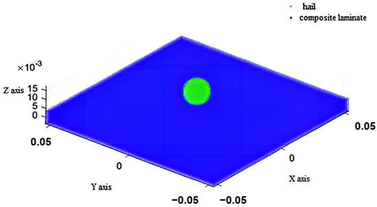
Figure 4.
Initial position of hailstone and composite laminate plate in impact simulation.
To simulate the high-speed hailstone impact on a composite laminate, the material parameters are inputted, and the relevant matrices are initialized. Then, the PD models for the hailstone and composite plate are established and discretized, with a virtual boundary introduced around the plate model. Next, the horizon matrix for the material points is generated, and the surface correction coefficient is calculated. The initial impact velocity of the hailstone was subsequently applied, and the support conditions were established at the virtual boundary. Time-domain integration is performed by identifying failures for each material point and calculating the sum of dynamic interaction forces within the horizon, along with short-range forces to derive displacement and velocity values. Finally, the results are output for visualization purposes. A flow chart illustrating the simulation process is shown in Figure 5.
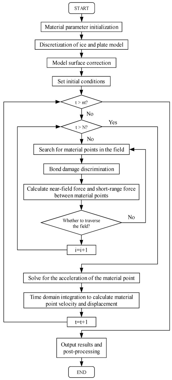
Figure 5.
Flow chart for the simulation of hailstone impact on composite laminate.
6. Dynamic Damage Analysis of Composite Laminate Under High-Speed Hailstone Impact
A coupling method is used to investigate the ability of a composite laminate structure to withstand hailstone impacts, as well as to analyze the damage and destruction processes following impact, based on the materials and methods outlined in Section 2, Section 3, Section 4 and Section 5.
6.1. General Damage to Composite Laminate
To determine the damage to the laminate resulting from the impact force, we selected the material point located at the center of the top layer (coordinates 0, 0, 0.035, as shown in Figure 4) as our focal point for establishing the temporal variation in impact force density, depicted in Figure 6. During the initial phase of impact, the impact force density reached its maximum value within a very short time frame before decreasing to a certain value and subsequently fluctuating constantly. The early maximum impact force density can be attributed to the initial collision of hailstone particles against the plate, which are continuously compressed by the remaining hailstone behind them, resulting in high pressure at the center of the hailstone face. During the intermediate stage of impact, the density of the impact force decreased to a minimum before gradually increasing to reach a local peak value. In the later stage of impact, the impact force density rapidly diminished to zero.
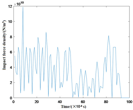
Figure 6.
Change in impact force density at the material point in the mid-thickness at the center of the top layer.
The progressive damage process of a composite laminate subjected to hailstone impact can be characterized by monitoring the force density in both the top and bottom layers, along with the corresponding damage rates of the three bond types. Under the impact of a high-speed hailstone, the damage observed in both the top and bottom laminate layers has been identified as the most serious and representative. Consequently, the progressive damage process of composite laminates is investigated with a focus on these two layers.
6.2. Progressive Damage Process of Top Layer
The force densities in the top layer of the composite laminate during impact are shown in Figure 7. This figure reveals that the impact area itself exhibited the highest force density in a circular shape. Additionally, it clearly demonstrates propagation of stress waves within the top layer during impact, with the point of contact serving as the center of this circular pattern and stress radiating outward. Wave rebound and interference occurred when the stress wave diffused to the fixed support boundary. Due to the higher Young’s modulus in the direction of the composite fibers compared to other directions, the propagation velocity of the stress wave along the fiber axis is significantly greater, resulting in an increased force density at the impact location and a pronounced spindle formation aligned with the fiber direction of the top layer. The fiber orientation is designated as direction X in Figure 7.
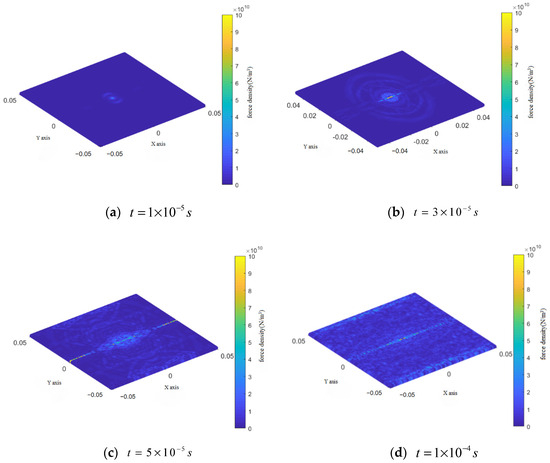
Figure 7.
Change in force density in the top layer during the impact process.
The final damage rates for the three bond types in the top layer during impact are shown in Figure 8 for the fiber bonds, Figure 9 for matrix bonds, and Figure 10 for the interlaminar bonds with the underlying layer.
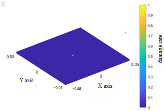
Figure 8.
Final damage rate of the fiber bonds of the top layer.
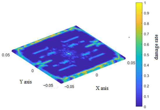
Figure 9.
Final damage rate of the matrix bonds of the top layer.
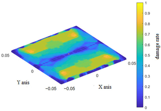
Figure 10.
Final damage rate of the interlaminar bonds between the top and underlying layers.
During the impact process discussed in Section 6.1, the fiber bonds in the top layer broke only at the impact location. Damage to the matrix bonds initially occurred at the impact location and propagated in localized strips perpendicular to the fibers before extending rapidly along the fiber direction towards the retaining boundary. Damage to the interlaminar bonds occurred in two sectors extending perpendicular to the fibers, and lessened at the retaining boundary parallel to the fiber direction.
6.3. Progressive Damage Process of Bottom Layer
The force densities in the bottom layer of the composite laminate during impact are shown in Figure 11.
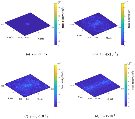
Figure 11.
Change in force density in the bottom layer during the impact process.
The variation in force density within the bottom layer during the early stage of impact is similar to that observed in the top layer, with the force density distribution exhibiting a ring around the impact location. However, in the intermediate and late stages, the force density distribution manifested as a butterfly shape perpendicular to the fiber direction, with no stress concentration evident at the retaining boundary parallel to this direction.
The fiber bonds of the bottom layer are not damaged during the impact. The final damage rates for the matrix bonds of the bottom layer and interlaminar bonds between the bottom layer and overlying layer are shown in Figure 12 and Figure 13, respectively.
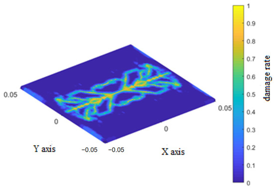
Figure 12.
Final damage rate of the matrix bonds of the bottom layer.
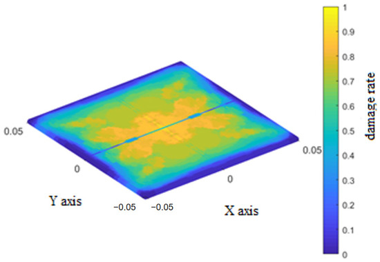
Figure 13.
Final damage rate of the interlaminar bonds of the bottom layer.
During the early stage of impact, damage to the matrix bonds in the bottom layer manifested at the center of the impact location in a dumbbell shape, expanding dendritically towards both ends along the fiber direction. Similarly, damage to the interlaminar bonds also occurred at the impact center and then extended in regions on both sides of the layer, perpendicular to the fiber direction.
During the intermediate stage of impact, damage to the matrix bonds continued to expand dendritically towards both ends along the fiber direction until it spanned the entire layer. Similarly, damage to the interlaminar bonds extended across the entire lower layer and gradually increased, resulting in an ‘X’ pattern.
In the late stage of impact, adjacent instances of dendritic damage to the matrix bonds began to connect, forming a butterfly-like pattern. The damage to the interlaminar bonds further worsened along the fiber direction, showing symmetrical wavy lines relative to this direction.
6.4. Verified Through Experiment
To verify the rationality of the butterfly-shaped crack propagation morphology of the laminated board under hail impact obtained from this simulation, we designed corresponding impact experiments. The experiment used composite laminate specimens identical to the simulation, with rigid fixture boundary constraints around them. The impact experiment simulated hail impact using a gas cannon firing device, with a spherical ice bullet with a diameter of 15 mm impacting the center of the plate at a speed of 100 m/s. After the impact, CT scanning was used to observe the internal and surface damage morphology of the sample, as shown in Figure 14.
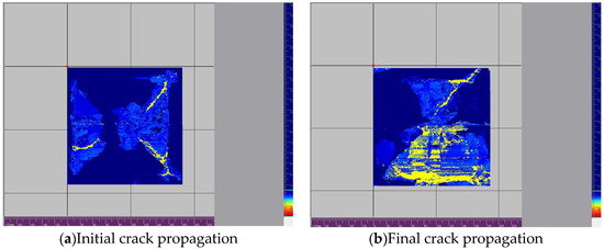
Figure 14.
The crack scanning image of the impact test.
The crack propagation morphology observed in the experiment is shown in the figure. The results indicate that a typical butterfly-shaped crack network was formed around the impact point and symmetrically extended along the fiber direction. The main features of this morphology are highly consistent with the simulation results: (1) the crack propagates along the main directions of the 0°and 90° layers, showing clear orthogonal symmetry; (2) The crack radiates outward from the impact center, branching and turning at the interface between adjacent layers, forming the ‘butterfly wing’ pattern seen in the simulation; (3) The contour of the damaged area displayed in CT images matches well with the simulated damage cloud map in terms of shape and size.
The formation of this specific crack morphology is rooted in the damage mechanics mechanism of orthogonal laminated panels under high-speed impact. The complex three-dimensional stress waves generated by hail impact will preferentially induce crack propagation along its transverse direction in a single-layer plate with strong anisotropy. For the [0°/90°] symmetric layup, this directly leads to an orthogonal crack network in the 0° and 90° directions. When cracks propagate to the layer interface, the deformation caused by the orthogonal direction of adjacent layer fibers is not coordinated, resulting in significant interlayer shear stress, which drives the cracks to layer and turn at the interface, and continue to propagate in the new weak direction in adjacent layers. This process, which repeatedly occurs in multiple layers and is dominated by in-plane tension and inter-layer shear, ultimately forms a ‘butterfly shaped’ three-dimensional damage cluster that diverges symmetrically from the impact center. This form is essentially the result of the dissipation of impact energy along the most effective path within the anisotropic framework of the material.
In summary, the observed crack morphology, symmetry characteristics, and damage distribution in the experiment effectively validated the rationality of the simulation model in predicting the crack propagation and butterfly-shaped crack formation mechanism of composite laminates under hail impact. Although there are some differences in the prediction of fine branch cracks, the simulation shows reliable accuracy in macroscopic morphology, dominant propagation direction, and damage mode, indicating that the finite element model and related parameters established in this study can effectively simulate the damage behavior of laminated plates under hail impact.
6.5. Process Analysis
The progressive damage process of a composite laminate subjected to hailstone impact can be summarized by observing the force density in both the top and bottom layers of the laminate, along with the corresponding damage rates of the three types of bonds.
- (1)
- The destruction of matrix and interlaminar bonds represented the primary damage mechanism during hailstone impact on the composite laminate. This finding is in agreement with the experimental results presented in the literature, which mainly consisted of matrix failures and delamination failures.
- (2)
- The damage observed in the top and bottom layers is not identical. Damage to the fiber bonds occurred exclusively in the top layer, as did damage to the matrix and interlaminar bonds aligned with the fiber direction at the retaining boundary. Furthermore, the final damage morphologies of both matrix and interlaminar bonds differed between the top and bottom layers.
- (3)
- The fiber bonds exhibited a significant influence on the impact resistance of the composite laminate. The force density clouds obtained in this study indicated that the force density along the fiber direction at the impact location is significantly higher than that observed at other locations during the impact process.
- (4)
- The damage propagation paths of the interlaminar shear bonds and matrix bonds exhibited distinct characteristics. The damage propagation paths of the interlaminar bonds are sector-shaped on either side of the impact point, oriented perpendicular to the fiber direction. The damage propagation paths of the matrix bonds originated from the impact location and extended at a 45° angle relative to the fiber direction.
7. Conclusions
This study established a bond-based hail impact damage model for composite laminated panels to simulate the damage situation of an aircraft radome during flight when encountering hail. For this purpose, the impact process of hail on composite laminated panels, the mechanism of hail fragmentation, and the progressive damage behavior of composite laminated panels were analyzed.
The simulation results show that when hail impacts the composite laminated panel at a speed of 100 m/s, local displacement will occur in the laminated panel. As the hail moves towards the laminated panel, the number of damaged particles increases, causing the laminated panel to deform more severely. Once most of the hail particles are damaged, the deformation of the laminated panel will decrease. The damage first occurs at the weaker base bonding, where local damage occurs in the fiber direction and gradually spreads; subsequently, the fiber bonding ruptures, causing mixed damage. Through further dynamic damage process analysis, it was confirmed that the main failure mode of the composite laminated panel under high-speed hail impact is the base cracking and delamination cracking.
Therefore, this model is helpful in predicting the starting location, propagation path, and final failure mode of various types of damage during the impact process, which is of great significance for the design and evaluation of composite material structures such as radomes.
Author Contributions
Conceptualization, F.Z., Y.X., X.X., X.L. and Y.G.; Methodology, F.Z., Y.X., X.X. and L.B.; Software, F.Z.; Validation, L.B. and Y.G.; Formal analysis, F.Z., Y.X., X.X. and L.B.; Resources, Y.G.; Writing—original draft, F.Z., Y.X. and X.L. All authors have read and agreed to the published version of the manuscript.
Funding
The authors gratefully appreciate the support of the Key R&D Program of Jiangxi Province (20243BBG71006).
Data Availability Statement
Data are contained within the article.
Conflicts of Interest
The authors declare no conflict of interest.
References
- Fernandes, R.R.; Tamijani, A.Y.; Al-Haik, M. Mechanical characterization of additively manufactured fiber-reinforced composites. Aerosp. Sci. Technol. 2021, 113, 106653. [Google Scholar] [CrossRef]
- Goda, I.; Girardot, J. A computational framework for energy absorption and damage assessment of laminated composites under ballistic impact and new insights into target parameters. Aerosp. Sci. Technol. 2021, 115, 106835. [Google Scholar] [CrossRef]
- Anwar, W.; Khan, M.Z.; Israr, A.; Mehmood, S.; Anjum, N.A. Effect of structural dynamic characteristics on fatigue and damage tolerance of aerospace grade composite materials. Aerosp. Sci. Technol. 2017, 64, 39–51. [Google Scholar] [CrossRef]
- Sun, Z.Q.; Wu, A.R. Application of Advanced Composite Materials in Aircraft Structures. Mater. Rep. 2015, 61–64, 69. [Google Scholar]
- Li, J.T.; Yuan, M.F. Summary of High-Speed Hail Impact Research on Aviation Composite Structure. In Proceedings of the Exploration and Innovation Exchange (Seventh Episode)-7th China Aviation Society Youth Science and Technology Forum, Nanchang, China, 30 October 2016. [Google Scholar]
- Kim, H.; Kedward, K.T. Modeling hail ice impacts and predicting impact damage initiation in composite structures. AIAA J. 2000, 38, 1278–1288. [Google Scholar] [CrossRef]
- Zhao, W.; Gupta, A.; Christopher, D.R.; Miglani, J.; Rakesh, K.K.; Peter, J.S. Component data assisted finite element model updating of composite flying-wing aircraft using multi-level optimization. Aerosp. Sci. Technol. 2019, 95, 105486. [Google Scholar] [CrossRef]
- Lal, A.; Shailesh, P.P.; Sameer, B.M.; Rakesh, K.K. Stochastic extended finite element implementation for fracture analysis of laminated composite plate with a central crack. Aerosp. Sci. Technol. 2017, 60, 131–151. [Google Scholar] [CrossRef]
- Ha, S.K.; Keilers, C.; Chang, F.K. Finite element analysis of composite structures containing distributed piezoceramic sensors and actuators. AIAA J. 1992, 30, 772–780. [Google Scholar] [CrossRef]
- Tvergaard, V.; Hutchinson, J.W. The relation between crack growth resistance and fracture process parameters in elastic-plastic solids. J. Mech. Phys. Solids 1992, 40, 1377–1397. [Google Scholar] [CrossRef]
- Song, Y.; Yan, J.; Li, S.; Kang, Z. Peridynamic modeling and simulation of ice craters by impact. Comput. Model. Eng. Sci. 2019, 121, 465–492. [Google Scholar] [CrossRef]
- Sun, B.; Li, S.; Gu, Q.; Ou, J. Coupling of peridynamic and numerical substructure method for modeling structures with local discontinuities. Comput. Model. Eng. Sci. 2019, 120, 739–757. [Google Scholar] [CrossRef]
- Lai, X.; Liu, L.; Li, S.; Zeleke, M.; Liu, Q.; Wang, Z. A non-ordinary state-based peridynamics modeling of fractures in quasi-brittle materials. Int. J. Impact Eng. 2018, 111, 130–146. [Google Scholar] [CrossRef]
- Xue, Y.; Liu, R.; Liu, Y.; Zeng, L.; Han, D. Numerical Simulations of the Ice Load of a Ship Navigating in Level Ice Using Peridynamics. Comput. Model. Eng. Sci. 2019, 121, 523–550. [Google Scholar] [CrossRef]
- Hu, Z.L.; Yu, Y.; Wang, H. Modeling and progressive damage analysis of composite laminates based on peridynamics. In Proceedings of the 17th National Symposium on Composite Mechanics (Sub-Forum on Composite Mechanics), Shanghai, China, 13 October 2012; pp. 123–128. [Google Scholar]
- Hu, Z.L. Modeling and Analysis of FRP Laminates Based on Peridynamics; Shanghai Jiaotong University: Shanghai, China, 2013. [Google Scholar]
- Yang, X.W. Progressive Damage Simulation of Composite Laminates Based on Peridynamics; Harbin University of Technology: Harbin, China, 2018. [Google Scholar]
- Guo, S.; Jiao, X.J.; Li, L.J.; Dong, X.H.; Sun, F.S. Progress in peridynamic method to study composite material failure. Mater. Rep. 2019, 33, 826–833. [Google Scholar]
- Stewart, A.S.; Askari, E. A meshfree method based on the peridynamic model of solid mechanics. Comput. Struct. 2005, 83, 1526–1535. [Google Scholar] [CrossRef]
- Wang, L.-F.; Zhou, X.-P. A field-enriched finite element method for simulating the failure process of rocks with different defects. Comput. Struct. 2021, 250, 106539. [Google Scholar] [CrossRef]
- Xu, J.; Askari, A.; Weckner, O.; Silling, S. Peridynamic Analysis of Impact Damage in Composite Laminates. J. Aerosp. Eng. 2008, 21, 187–194. [Google Scholar] [CrossRef]
- Kilic, B.; Agwai, A.; Madenci, E. Peridynamic theory for progressive damage prediction in center-cracked composite laminates. Compos. Struct. 2009, 90, 141–151. [Google Scholar] [CrossRef]
- Silling, S.A. EMU User’s Manual, Code Ver. 2.6D; A National Laboratories: Albuquerque, NM, USA, 2004. [Google Scholar]
- Armero, F.; Linder, C. Numerical simulation of dynamic fracture using finite elements with embedded discontinuities. Int J Fract. 2009, 160, 119–141. [Google Scholar] [CrossRef]
- Nikolić, M.; Do, X.N.; Ibrahimbegovic, A.; Nikolić, Ž. Crack propagation in dynamics by embedded strong discontinuity approach: Enhanced solid versus discrete lattice model. Comput. Methods Appl. Mech. Eng. 2018, 340, 480–499. [Google Scholar] [CrossRef]
- Wang, Y.; Zhou, X.; Wang, Y.; Shou, Y. A 3-D conjugated bond-pair-based peridynamic formulation for initiation and propagation of cracks in brittle solids. Int. J. Solids Struct. 2018, 134, 89–115. [Google Scholar] [CrossRef]
- Huang, D.; Zhang, Q.; Qiao, P.Z.; Sheng, F. Peridynamics and its applications. Adv. Mech. 2010, 40, 448–459. [Google Scholar]
- Silling, S.A.; Bobaru, F. Peridynamic modeling of membranes and fibers. Int. J. Non-Linear Mech. 2005, 40, 395–409. [Google Scholar] [CrossRef]
- Silling, S.A.; Lehoucq, R.B. Convergence of Peridynamics to Classical Elasticity Theory. J. Elast. 2008, 93, 13–37. [Google Scholar] [CrossRef]
- Seleson, P.; Parks, M.L.; Gunzburger, M.; Lehoucq, R.B. Peridynamics as an Upscaling of Molecular Dynamics. Multiscale Model. Simul. 2009, 8, 204–227. [Google Scholar] [CrossRef]
- Fan, H.; Bergel, G.L.; Li, S. A hybrid Peridynamics-SPH simulation of soil fragmentation by blast loads of buried explosive. Int. J. Impact Eng. 2015, 87, 14–27. [Google Scholar] [CrossRef]
- Shi, C.; Shi, Q.; Tong, Q.; Li, S. Peridynamics modeling and simulation of mesoscale fracture in recycled coarse aggregate (RCA) concretes. Theor. Appl. Fract. Mech. 2021, 126, 103009. [Google Scholar]
- Xiong, W.P.; Wang, C.; Fu, J.Y.; Wang, C.H.; Cao, C.J. Numerical simulation of near-field dynamics method for ice hockey impact test. Vib. Impact 2020, 9, 148–155. [Google Scholar]
- Yile, H. Modeling and Analysis of FRP Laminates Based on Near-Field Dynamics; Shanghai Jiao Tong University: Shanghai, China, 2013. [Google Scholar]
- Stamoulis, K.; Georgantzinos, S.K.; Giannopoulos, G. Damage characteristics in laminated composite structures subjected to low-velocity impact. Int. J. Struct. Integr. 2019, 11, 670–685. [Google Scholar] [CrossRef]
- Wan, R.; Jin, P.; Tan, X.M.; Wang, D. Low-speed impact damage analysis of composites based on ABAQUS. Equip. Environ. Eng. 2014, 11, 38–42. [Google Scholar]


Disclaimer/Publisher’s Note: The statements, opinions and data contained in all publications are solely those of the individual author(s) and contributor(s) and not of MDPI and/or the editor(s). MDPI and/or the editor(s) disclaim responsibility for any injury to people or property resulting from any ideas, methods, instructions or products referred to in the content. |
© 2025 by the authors. Licensee MDPI, Basel, Switzerland. This article is an open access article distributed under the terms and conditions of the Creative Commons Attribution (CC BY) license.