Abstract
This study proposes a novel variable-radius arc rotor, developed based on the conventional arc rotor, for application in a hydrogen circulation pump. Numerical simulations are conducted to analyze and compare the flow characteristics of the optimized rotor with those of the baseline rotor. Results show that the optimized rotor increases outlet mass flow rates by over 15%; however, it has little effect on pressure pulsation, indicating limited influence on flow stability. Flow field analysis reveals that the optimized rotor promotes a more stable and streamlined internal velocity distribution, suppressing localized disturbances and vortices that are prevalent with the baseline rotor. Furthermore, assessments of turbulent kinetic energy (TKE) and three-dimensional vortex structures show that the optimized rotor confines high-energy zones to essential areas and facilitates controlled vortex evolution. These effects collectively lead to lower turbulence intensity, reduced energy loss, improved operational efficiency, and enhanced mechanical reliability of the pump.
1. Introduction
With the continuous growth of the global population, increasing energy demands, worsening environmental pollution, and the gradual depletion of fossil fuels, there is an urgent need to develop sustainable energy production methods [1,2]. Among various new energy options, hydrogen energy has gradually been recognized as a key direction for future energy development due to its wide availability, high energy density, and zero carbon emissions. In particular, hydrogen produced through green methods such as electrochemical or photochemical water splitting further highlights its environmental friendliness and sustainability potential [3,4]. Hydrogen can be utilized in various ways: as an industrial raw material in chemical production, for energy storage and grid balancing, and, because its combustion product is only water, it is widely considered an important pathway to achieving carbon peaking and carbon neutrality goals [5,6]. In recent years, with continuous technological advancements, an efficient and environmentally friendly hydrogen utilization method—hydrogen fuel cells—has gradually come into focus. Hydrogen fuel cells convert hydrogen into electricity through electrochemical reactions, offering advantages such as high efficiency, quiet operation, and zero pollutant emissions. They also show broad application prospects in transportation, distributed power generation, portable power supplies, and other fields [7,8,9].
However, during the actual operation of hydrogen fuel cells, an excess of hydrogen is typically supplied to the anode side to ensure sufficient reaction and improve cell efficiency. Since hydrogen utilization is not 100%, a considerable portion of unreacted hydrogen remains in the anode exhaust gas [10,11]. If this unreacted hydrogen is directly released into the atmosphere, it not only results in energy waste and increased operating costs but also poses significant safety risks due to hydrogen’s high flammability and diffusivity, especially in confined or semi-enclosed environments [12]. To address this issue, hydrogen recirculation pumps are commonly used to recover hydrogen from the anode exhaust. These devices pressurize the exhaust hydrogen and reintroduce it into the anode inlet, enabling a closed-loop hydrogen cycle. This approach improves hydrogen utilization efficiency and reduces overall hydrogen consumption while effectively mitigating safety hazards [13,14]. Additionally, the hydrogen recirculation system helps regulate gas flow and pressure on the anode side, contributing to enhanced operational stability and longer fuel cell lifespan. Consequently, hydrogen recirculation pumps have become an indispensable component in the design of modern proton exchange membrane fuel cell (PEMFC) systems [15].
The hydrogen recirculation pump is essentially a low-pressure-ratio gas compression device whose primary function is to pressurize the unreacted hydrogen in the anode exhaust of a hydrogen fuel cell and reintroduce it into the anode, thereby enabling hydrogen recycling. Since the operating pressure in fuel cell systems is generally low, the required compression ratio is relatively small. Therefore, compression mechanisms suitable for low-pressure differentials and continuous gas delivery—such as scroll pumps, screw compressors, and Roots compressors—can be selected [16]. Among these options, Roots compressors are preferred for hydrogen recirculation pumps due to their simple structure, stable operation, large flow capacity, and low requirements for gas cleanliness [17]. Compared with other types of compressors, Roots compressors feature no internal compression and employ forced exhaust, which reduces gas temperature rise and contamination during delivery, making them especially suitable for hydrogen fuel cell systems that demand high gas purity [18]. Additionally, Roots compressors achieve high efficiency under low-pressure-ratio conditions and are easy to miniaturize and modularize, which makes them particularly ideal for hydrogen circulation in passenger vehicles and portable fuel cell systems. The core components of a Roots-type hydrogen recirculation pump are two intermeshing lobed rotors, typically arranged in a figure-eight or composite profile pattern, and driven in relative rotation by synchronized gears. During rotation, the rotors and pump casing form sealed working chambers that accomplish the intake, transport, and discharge of hydrogen. Thus, the rotor profile design directly influences critical performance parameters such as volumetric efficiency, gas tightness, noise control, and mechanical strength [19].
Currently, many researchers have conducted in-depth studies on the rotor profiles of Roots compressors, aiming to optimize rotor meshing accuracy, reduce leakage gaps, and improve compression efficiency. For instance, Hwang and Hsieh [20] proposed a method to enhance vacuum pump performance by utilizing an extended cycloid curve with a variable trochoid ratio. By applying third- and fifth-order polynomials with carefully designed boundary conditions, they generated a smooth trochoid ratio function and a corresponding regular addendum curve for the Roots rotor. The complete rotor tooth profile was then derived from this curve, with its feasibility validated through undercutting and carryover analyses. Finally, the authors presented a design strategy aimed at achieving high volumetric efficiency in vacuum systems. Zhou et al. [21] proposed a novel rotor profile for Roots pumps designed for hydrogen fuel cell vehicles. The results indicate that, under the same number of lobes, the maximum area utilization of the new rotor profile is approximately 10.4% higher than that of conventional profiles. Numerical simulations confirmed that the novel profile offers advantages in enhancing flow rate and sealing performance. Specifically, the concentric arc structure at the rotor tip reduces radial clearance, thereby minimizing internal leakage, while the multipoint meshing characteristics within a specific angular range effectively reduce inter-lobe leakage. Yao et al. [22] proposed a novel three-lobe helical rotor for Roots blowers, featuring a cross section that combines concave and convex arcs with cycloidal curves. Their study demonstrates that this design improves airflow and reduces peak blower pressure compared to conventional straight-tooth rotors. Li et al. [23] investigated the effects of variable diameter ratio rotor profiles on the flow characteristics of hydrogen circulation pumps. The results show that the variable trochoid ratio enhances inlet and outlet flow pulsations—especially at the inlet—reduces vortex formation and leakage in the suction chamber, and increases the chamber volume due to higher area utilization. These effects contribute to improved inlet flow and overall pump performance. Bhuyan and Ghosh [24] conducted a study on rotor profile design by defining a 2-lobe rotor shape using three arcs and parameterizing it with two independent parameters. They investigated the impact of different rotor-profile shapes on the unsteady internal hydrodynamics and heat transfer of a Roots blower through transient finite volume simulations combined with an adaptive moving mesh technique. Their analysis revealed that key flow characteristics, including pressure, velocity, temperature, leakage, and backflow, are highly sensitive to rotor-profile shape. Zhai et al. [25] conducted a comprehensive study on the design and flow performance of rotor profiles for Roots-type hydrogen circulation pumps. They proposed a general rotor profile design formula based on conjugation theory, which was validated using four different rotor geometries: two-tangent-arcs, single-arc, ellipse, and quadratic-curve profiles. The results showed that the single-arc profile rotor exhibited the best overall performance in terms of flow rate and flow stability. The ellipse profile rotor ranked second, offering a well-balanced performance. While the quadratic-curve profile rotor achieved the highest average flow rate, it demonstrated poor flow stability. In contrast, the two-tangent-arcs profile rotor yielded the lowest average flow rate. Li et al. [26] present a novel six-lobe Roots rotor profile aimed at enhancing the performance of Roots blowers for hydrogen fuel cell vehicles. Their study highlights the critical balance between rotor cavity volume and adiabatic indicated efficiency. The proposed rotor profile expands design flexibility by allowing adjustments in tooth height and effectively managing leakage through modifications of the blow-hole and contact line. As a result, it achieves superior adiabatic indicated efficiency compared to conventional Roots profiles at equivalent rotor cavity volumes, providing valuable insights for optimizing Roots blower designs in fuel cell applications. Wang and Yan [27] investigated a novel circular-arc epitrochoid rotor profile for application in hydrogen circulation pumps for fuel cells. They evaluated the internal flow characteristics and performance of the new rotor. The results showed that the new profile increased outlet flow rate by 14.28% and significantly reduced flow and pressure pulsations compared to traditional external cycloidal designs.
Previous studies have demonstrated that the rotor profile has a significant impact on the key performance metrics of Roots-type hydrogen circulation pumps, including volumetric efficiency, leakage characteristics, and operational stability. Based on these insights, this study takes the conventional three-lobe circular-arc rotor as a starting point and proposes an optimized design featuring a modified profile composed of four arc segments with variable-radius arcs. To evaluate the effectiveness of the proposed design, numerical simulations were conducted to compare the flow characteristics and overall performance of the baseline and optimized rotors under the same operating conditions. The optimized rotor demonstrates notable advantages, including increases of 15.64% in mass flow rate at the outlet. The modified profile also promotes the formation of a more stable and streamlined velocity field, suppressing localized velocity spikes and unnecessary vortices, which reduces flow resistance, improves gas delivery uniformity, and alleviates mechanical stress on internal components. Furthermore, evaluations of turbulent kinetic energy and three-dimensional vortex structures confirm that the new rotor confines high-energy regions to functional zones, reduces turbulence intensity, and enhances energy regulation within the flow field. These advancements highlight the potential of the variable-radius arc rotor to address existing limitations in hydrogen circulation pump design, offering a promising pathway toward more efficient and robust hydrogen energy systems.
2. Profile Design
The arc-shaped rotor is primarily composed of a circular arc segment and its conjugate curve, as illustrated in Figure 1. Therefore, to fully delineate the rotor’s profile, it is necessary to derive the equation of the conjugate curve. Among the available methods, coordinate transformation provides an efficient approach for determining the conjugate curve. To obtain the conjugate curve using coordinate transformation, it is essential to establish two static coordinate systems and two moving coordinate systems, as depicted in Figure 2.
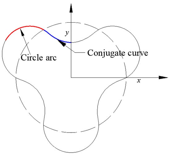
Figure 1.
Profile of the arc rotor.
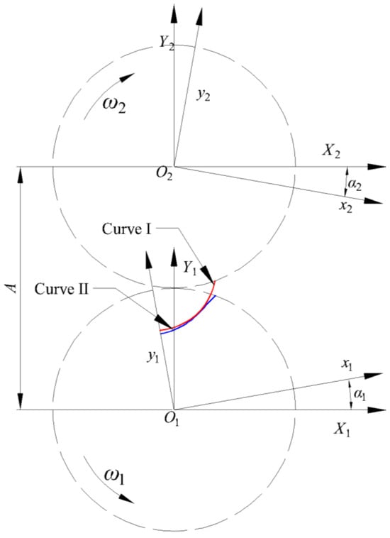
Figure 2.
Schematic diagram of coordinate system transformation.
In Figure 2, X1O1Y1 and X2O2Y2 represent the static coordinate systems, separated by a distance A. Meanwhile, x1O1y1 and x2O2y2 denote the moving coordinate systems, rotating in opposite directions with angular velocities ω1 and ω2, respectively. Based on their rotational relationship, the transformations between these coordinate systems can be derived.
Thus, the transformation between X1O1Y1 and x1O1y1 is given by:
The transformation between X1O1Y1 and X2O2Y2 is given by:
where A is the fixed offset between the two static coordinate systems.
The relationship between X2O2Y2 and x2O2y2 is given by:
Therefore, the relationship between x1O1y1 and x2O2y2 can be derived as:
where i represents the transmission ratio between the two rotors.
As illustrated in Figure 2, if Curve I and Curve II represent the conjugate tooth profiles on mating rotors 1 and 2, respectively, the following kinematic relationship can be established: When counter-rotating angular velocities of -ω2 are simultaneously applied to both rotors, rotor 2 becomes stationary while rotor 1 undergoes pure rolling motion about rotor 2. During this pure rolling motion, Curve I and Curve II generates a family of curves (Curve Family 1). At any instant, Curve 2 on rotor 2 must maintain tangential contact with one member of Curve Family 1. The only geometric entity satisfying this continuous tangency condition is the envelope of Curve Family 1. Therefore, Curve 2 on rotor 2 necessarily corresponds to this envelope, demonstrating the fundamental envelope principle.
Assume that the equation of Curve I in the coordinate system x1O1y1 is given by
Accordingly, the equation of the family of curves is
By applying a coordinate transformation, Equation (6) is converted into the coordinate system x2O2y2, resulting in
For the curve family 1, the slope of an arbitrary curve is
For Curve II, the slope is given by
According to the envelope condition, the slope of the envelope must be equal to that of a specific curve in the curve family 1 at the point of tangency. Therefore,
Taking the partial derivatives of Equation (10) with respect to α1 and t, respectively, yields:
Substituting Equation (11) into Equation (10) yields:
Since the rotational speeds of Rotor 1 and Rotor 2 are equal, we have i = 1. Moreover, the distance between the two rotors is equal to twice the pitch circle radius R. Therefore, the above equation simplifies to:
Therefore, for an arc-shaped rotor, once the parametric equation of its arc is known, the conjugate curve can be determined based on the coordinate transformation relationships.
For an arc-shaped rotor, the parametric equation of the arc is given by:
where r is the radius of the arc, and b is the distance from the center of the arc to the origin of the coordinate system.
So, the parametric equation conjugate curve of arc is
After determining the envelope curve of the arc, the complete geometry of the arc rotor can be generated based on this result. Figure 3 illustrates the arc and the corresponding envelope curve for a three-lobe arc rotor. In Figure 3, Rt denotes the radius of the addendum arc, and R represents the pitch circle radius. However, there are some limitations of conventional arc-shaped rotors have been identified in both theoretical analysis and practical applications. Due to the discontinuity in curvature between adjacent arc segments, which can lead to increased leakage and reduced volumetric efficiency. As constant-radius arcs limit the potential for profile refinement and do not easily accommodate varying operating conditions. Resulting from abrupt curvature transitions that negatively affect the fluid dynamics in compression or expansion chambers. To overcome these shortcomings, the original arc segments are replaced with variable-radius arcs, allowing for a smoother curvature transition along the rotor profile. In addition, an addendum arc is introduced at the tooth tip to refine the sealing region and reduce clearance losses. Through this, it can improve sealing performance, especially at the tooth tips, leading to enhanced volumetric efficiency. Smoother conjugate curves, which facilitate better meshing with the mating rotor and reduce design complexity.
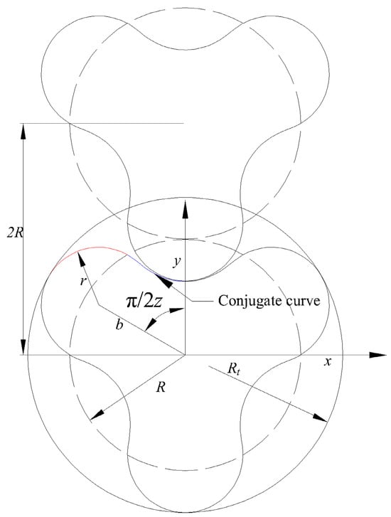
Figure 3.
Schematic diagram of an arc-shaped rotor.
The variable-radius arcs
As shown in Figure 4, a comparison between a constant-radius arc and a variable-radius arc is illustrated. For the constant-radius arc, the radius remains unchanged throughout. In contrast, the corresponding variable-radius arc has a radius defined as:
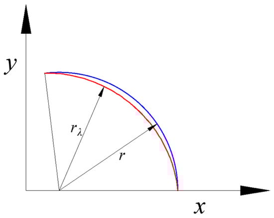
Figure 4.
Comparison between constant-radius arc and variable-radius arc.
In Equation (16), λ(θ) is a control function, with the lower bound λ(θ1) = 1 and upper bound λ(θ2) = 1. Except at these boundary points, λ(θ) < 1 throughout the domain. Various types of functions can be used to construct λ(θ); in this study, a sine function is adopted for its smoothness and simplicity.
The new rotor profile is shown in Figure 5. In this profile, segment AB is an addendum arc (tooth tip arc), segment BC is a variable-radius arc, segment CD is the envelope curve corresponding to segment BC, and segment DE is the envelope of segment AB. The parametric equations for each segment are given as follows:
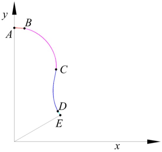
Figure 5.
The Schematic diagram of new profile.
Segment AB
Segment BC
Segment CD
Segment DE
Since there exists a practical clearance δ1 between the rotors, the theoretical profile must be modified accordingly. Therefore, the corrected (or modified) parametric equations are given as:
Segment AB
Segment BC
Segment CD
Segment DE
The two pump rotors were designed based on an identical set of parameters-such as the center distance, cylinder diameter, rotor length, and operational clearances-as detailed in Table 1.

Table 1.
Key parameters of hydrogen circulation pump.
3. Simulation Setup and Validation
3.1. Mesh Generation
To achieve high-accuracy simulation of the unsteady internal flow in a hydrogen circulation pump, a structured hexahedral mesh was employed for the discretization of the pump’s flow domain. The computational model primarily consists of two regions: a stationary domain and a rotating domain, each serving distinct functions in the overall flow system. The stationary domain includes the inlet pipe, inlet connection section, outlet connection section, and outlet pipe, which are responsible for guiding the working fluid into and out of the pump. The rotating domain comprises the rotor region and axial clearances, where dynamic interaction occurs between the rotors and the surrounding geometry, as illustrated in Figure 6.
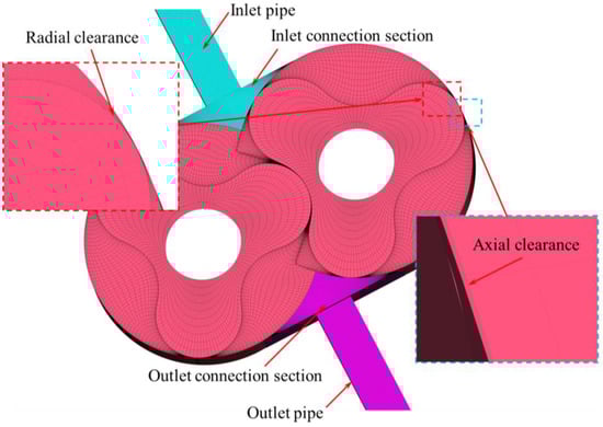
Figure 6.
Computational domain grid.
Given that the pump under investigation adopts a straight-bladed three-lobe Roots rotor, which features periodic rotational symmetry and regular geometry, the stationary and rotating domains were meshed independently using structured hexahedral elements. This approach enhances numerical accuracy and solution stability, particularly important for complex transient simulations. Structured grids help minimize numerical diffusion and mesh-induced errors, making them ideal for capturing detailed flow features within regularly shaped rotating machinery. For the rotating domain, its mesh generation fully considers the time-varying geometry caused by rotor rotation. Since the three-lobe rotor completes one full operational cycle every 120° of rotation, the complete rotation cycle was discretized into 60 time steps, corresponding to 2° per step. Accordingly, a set of structured grids was generated for each rotational increment, resulting in 60 dynamic mesh files in total. During the unsteady simulation, these mesh files were read and applied sequentially based on time steps, thereby realizing accurate dynamic representation of rotor motion and enabling the capture of transient flow features within the pump. To further improve simulation fidelity, local mesh refinement was applied to critical clearance regions-specifically, the clearances between rotor blades and the chamber, as well as between adjacent rotors. These regions are prone to complex flow phenomena such as leakage flows, strong shear layers, and steep pressure gradients. Mesh refinement in these areas enhances the model’s ability to resolve such fine-scale effects, improving the overall reliability of the simulation results. Data communication between the stationary and rotating domains, as well as between the inlet and outlet connection regions, was facilitated via interfaces, which maintain physical continuity and numerical consistency across different mesh zones. This strategy ensures seamless coupling of the computational domains, essential for resolving the strongly coupled fluid–structure interactions inherent in rotating machinery.
3.2. Boundary Conditions and Turbulence Model
To ensure that the simulation results are of high engineering relevance and accurately represent the actual performance of the hydrogen circulation pump under different working conditions, a systematic and comprehensive setup of physical parameters and boundary conditions was implemented in this study. The inlet boundary was uniformly set to standard atmospheric pressure All wall boundaries were defined as No slip walls to realistically capture the boundary layer development between the pump housing and the rotating components. The wall treatment was set to automatic wall functions, allowing the solver to dynamically adapt near-wall turbulence modeling based on the local Reynolds number and grid resolution. Interfaces were defined between the stationary and rotating domains. This ensured effective data exchange and physical continuity across different computational subdomains, which is essential for accurately resolving the complex, transient interactions between moving and stationary components within the pump. When operating with pure hydrogen, the inlet-to-outlet pressure ratio was set to 1.21, and the inlet temperature was increased to 70 °C to reflect high-temperature hydrogen conditions. Across all simulation cases, the pump’s rotational speed was fixed at 3000 rpm, with a time step of 1.389 × 10⁻⁴ s, ensuring adequate temporal resolution to capture critical features of unsteady flow behavior at moderate rotational speeds.
For the turbulence modeling, the Shear Stress Transport (SST) k-ω model was adopted to simulate the internal flow dynamics of the hydrogen circulation pump. The SST k-ω model combines the robustness and near-wall accuracy of the standard k-ω model with the free-stream independence and turbulence transport capabilities of the k-ε model. It is particularly effective in predicting flow separation, vortex structures, backflow, and leakage flows, which are prevalent in complex internal geometries such as those found in Roots-type pumps. Numerous studies have demonstrated the advantages of the SST k-ω model in capturing unsteady turbulent features in rotating machinery and confined flow passages [28,29,30]. However, the SST k-ω model still exhibits limitations when applied to fully three-dimensional turbulence involving strong vortical interactions. SST k-ω is two-equation RANS models cannot fully resolve the complexities of vortex flow interactions in confined swirling geometries [31,32]. Nevertheless, considering its proven robustness and wide application in turbomachinery simulations, the SST k-ω model was deemed appropriate for the present study. In this study, the SST k-ω turbulence model was selected to accurately capture secondary flow phenomena such as flow separation, clearance leakage, and internal recirculation, thereby enhancing the reliability of the simulation results for design optimization and performance evaluation. The governing transport equations for k and ω in the SST k-ω model are expressed as follows:
3.3. Mesh Independence Verification
During the numerical simulation of the hydrogen circulation pump, the density of the mesh directly influence the accuracy and reliability of the results. Although increasing mesh resolution helps to capture complex flow structures more precisely—particularly gap flows, fluid recirculation, and localized separation phenomena—it also significantly increases computational resource consumption and solution time. Therefore, determining a reasonable mesh size that balances simulation accuracy and computational efficiency is critical. To ensure the simulation results satisfy the mesh independence criterion, a mesh independence study was conducted under the operating condition of 3000 rpm and an inlet-to-outlet pressure ratio of 1.21. Using the same mesh topology, the computational domain was locally refined to varying degrees in critical regions, such as rotor gaps and end-face clearances, while adjusting the minimum cell size across different test groups to maintain consistent overall mesh quality. The total number of mesh nodes was incrementally increased from approximately 900,000 to 1.5 million to evaluate the sensitivity of simulation results to mesh size.
As shown in Figure 7, the flow rate converges as the mesh size increases, with the variation progressively decreasing. When the mesh node count reaches about 1.2 million, changes in results are controlled within 1%, and further mesh refinement no longer significantly affects the outlet mass flow. This indicates that the numerical results have effectively become independent of mesh resolution, meeting the mesh independence criteria. Considering both computational accuracy and resource expenditure, a mesh model comprising 1,205,889 cells was selected as the basis for subsequent simulations in this study.
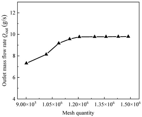
Figure 7.
Outlet mass flow rate at varying mesh densities.
3.4. Experimental Validation
To accurately validate the numerical simulation results, a dedicated experimental test rig was specifically designed and constructed to perform external characteristic tests on the hydrogen circulation pump. During the experimental campaign, multiple critical parameters including volumetric flow rate, pressure, and temperature were measured with high precision using calibrated instrumentation. The test platform integrates a comprehensive measurement system, enabling real-time data acquisition and control, with the schematic diagram and photographs of the apparatus illustrated in Figure 8. This advanced testing facility provides a robust and systematic approach to evaluating the pump’s performance, thereby ensuring the fidelity of the simulation model and its applicability to real-world operating conditions.
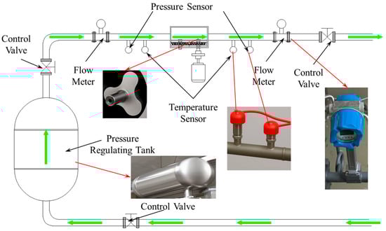
Figure 8.
Schematic and photographs of the test rig.
Considering the inherent safety risks and practical constraints associated with hydrogen gas testing, air was selected as the working medium during the experiments. The pump was operated at a constant rotational speed of 3000 rpm, with continuous intake and discharge of air through the system. To investigate the pump’s performance under different backpressure conditions, the outlet pressure was varied by adjusting a control valve installed at the downstream end of the outlet pipe, enabling stable operation at 1.01, 1.12, 1.21 and 1.32 times atmospheric pressure. All experimental boundary conditions, including fluid properties, temperature, and pressure, were carefully replicated in the numerical simulations to ensure consistency and facilitate direct comparison.
Figure 9 presents a comparative analysis between the experimentally measured average flow rates and the numerically simulated results of the hydrogen circulation pump under varying pressure ratios. As illustrated, the simulation data closely align with the experimental measurements across all tested pressure ratios, demonstrating good agreement and validating the accuracy of the numerical model. Quantitatively, the deviations between simulation and experiment remain within 5% for all five pressure ratio conditions examined. Notably, at a pressure ratio of 1.01, the relative error is as low as approximately 2%. Although the discrepancy between simulated and measured flow rates tends to slightly increase with rising pressure ratios, the error margins remain well within acceptable engineering limits. This slight growth in error may be attributed to factors such as experimental uncertainties, simplifications in boundary condition assumptions, or turbulence modeling limitations under higher backpressure scenarios. Nevertheless, the overall consistency between the two datasets confirms that the current numerical simulation framework reliably captures the complex internal flow phenomena within the hydrogen circulation pump, including leakage flows and flow separation. These results substantiate the effectiveness of the employed CFD approach for accurately predicting pump performance over a range of operating conditions, providing a solid foundation for its application in design optimization and operational analysis of hydrogen circulation systems. Therefore, the numerical model used in this study can be confidently applied for further research and analysis.
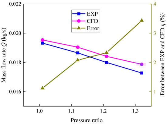
Figure 9.
Comparison of experimental and simulation data.
4. Results and Discussion
4.1. Pulsation of Flow Rate and Pressure
Figure 10 and Figure 11 illustrate the mass flow rate fluctuations at the inlet and outlet of the hydrogen circulation pump within a complete rotation cycle corresponding to the baseline and optimized rotor configurations, respectively. To further investigate the internal pressure dynamics within the exhaust chamber of the hydrogen circulation pump, a monitoring point was strategically placed inside the chamber. Figure 12 presents the pressure pulsation data recorded at this monitoring point for both rotors. Additionally, Table 2 presents the average mass flow rates at the inlet and outlet of the hydrogen circulation pump for both rotors.
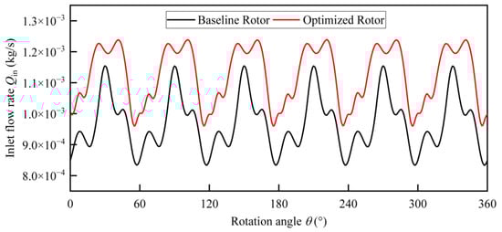
Figure 10.
Pulsation at the inlet of the hydrogen circulation pump for both rotors.
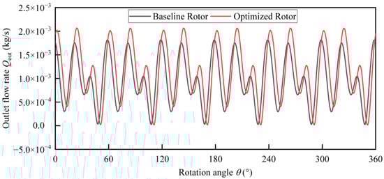
Figure 11.
Pulsation at the outlet of the hydrogen circulation pump for both rotors.
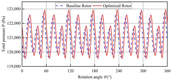
Figure 12.
Pressure pulsations of the hydrogen circulation pump measured at the monitoring point.
Table 2.
Average outlet mass flow rate of hydrogen circulation pump.
According to Figure 11, both the baseline and optimized rotors exhibit periodic mass flow pulsations that are tightly correlated with the rotor’s rotational cycle. This behavior is characteristic of Roots-type compressors, which operate based on the meshing motion of rotors that induces periodic variation in the working chamber volume. This volume fluctuation causes intermittent intake and discharge of gas, resulting in pulsatile flow at both the inlet and outlet. Specifically, as summarized in Table 2, the outlet mass flow rate increases by approximately 15.64%, indicating that the optimized geometry contributes to higher volumetric throughput without significantly altering the operating conditions. Moreover, the inlet flow from the optimized rotor exhibits more regular pulsation patterns, characterized by smoother peak-to-valley transitions. This improvement is a combined result of the stabilized intake and reduced internal leakage during rotor operation. According to leakage flow theory, minimizing inter-lobe or tip leakage not only increases effective gas delivery but also reduces energy loss due to unnecessary re-compression of backflow gas, thereby directly improving isentropic efficiency. This improvement stems from the refined rotor profile design which reduces flow resistance near the inlet port and mitigates flow separation and backflow. From a theoretical standpoint, this allows for more efficient utilization of the volumetric expansion created during the intake phase, thereby improving gas capture efficiency in accordance with the principles of unsteady compressible flow.
As shown in Figure 13, the exhaust pressure pulsation curves of the two rotors remain generally consistent, with only minor deviations observed at the peak values. Specifically, the optimized rotor exhibits a slightly higher maximum pressure and a slightly lower minimum pressure compared with the baseline, while the overall pulsation curve also demonstrates a subtle phase shift. This indicates that the adoption of a rotor composed of variable-radius arcs does not fundamentally alter the overall pulsation trend but instead introduces localized modifications in peak magnitudes and curve displacement. And the presence of this shift suggests that the primary effect of the optimized rotor lies not in redefining the pulsation pattern itself, but in fine-tuning the fluctuation characteristics and timing of pressure variations. Such behavior can be attributed to the refined rotor profile, which lowers inlet flow resistance, mitigates flow separation and backflow, and thereby alters the temporal progression of gas exchange. From a fluid-dynamic perspective, the curve displacement reflects adjustments in the phasing of the unsteady flow field, offering improved gas capture efficiency while maintaining overall pulsation stability.
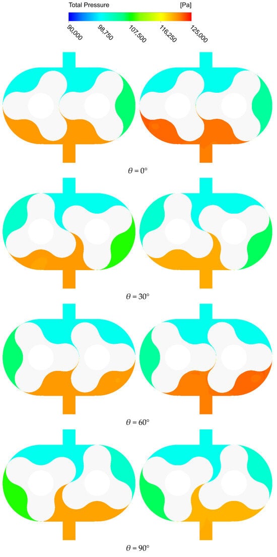

Figure 13.
Total pressure distribution in the hydrogen circulation pump.
In summary, the optimized rotor achieves a notable improvement in performance. Specifically, it delivers a higher volumetric throughput and exhibits more regular inlet pulsation patterns due to reduced leakage and stabilized intake. These benefits arise from refined geometric features that lower flow resistance, suppress backflow, and enhance gas capture efficiency. While the overall exhaust pressure pulsation trend remains largely unchanged, the optimized rotor introduces subtle adjustments in peak magnitudes and phase timing. Collectively, these findings indicate that the optimized rotor improves volumetric and isentropic efficiencies.
4.2. Variation in Internal Velocity and Pressure
Figure 13 illustrates the variation in total pressure along the axial central plane inside the hydrogen circulation pump for two rotors. The left panel depicts the total pressure distribution corresponding to the baseline rotor, while the right panel shows the results obtained using the optimized rotor. Figure 14 presents the velocity distribution and velocity vectors on the same axial central plane. The left side corresponds to the baseline rotor, while the right side represents the optimized rotor.
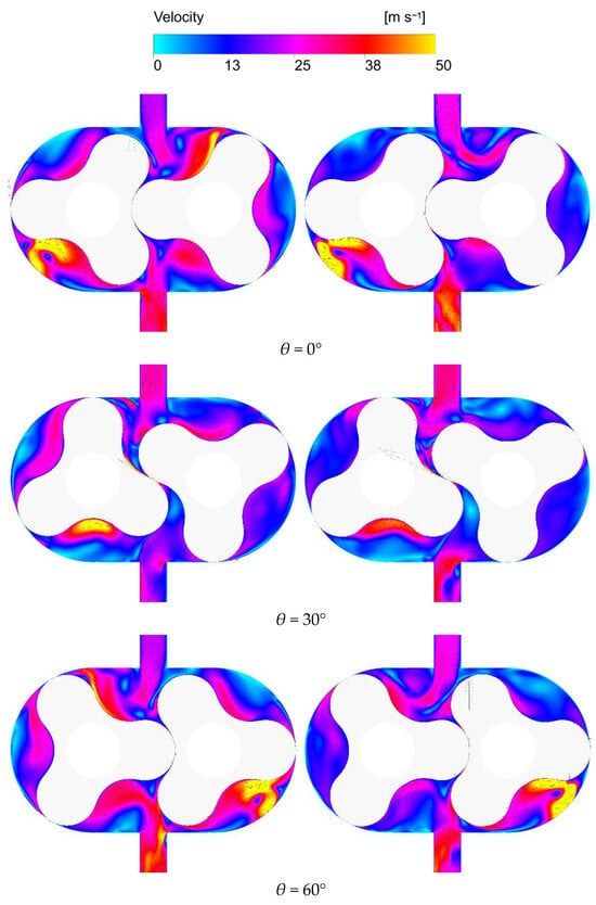
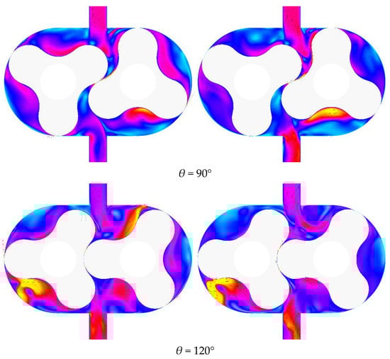
Figure 14.
Velocity distribution and velocity vector field in the hydrogen circulation pump.
As shown in Figure 13, the overall trends in pressure field variation are similar for both rotor profiles under different rotation angles. However, the rotor with the optimized profile exhibits a slightly higher pressure in the exhaust chamber throughout the rotation cycle. This difference is particularly evident at rotation angles of 0°, 60°, and 120°, where the optimized rotor consistently shows elevated exhaust chamber pressure. The observed pressure increase can be attributed to the improved sealing effect of the optimized profile, which effectively reduces leakage losses during the exhaust phase. As a result, the optimized rotor enhances gas delivery efficiency and improves the overall performance of the pump.
In contrast to the pressure field behavior, Figure 14 reveals distinct differences in the velocity field distribution between the two rotors. For the baseline rotor, localized high-velocity regions are observed at various rotation angles, particularly near the exhaust chamber, rotor clearances, and chamber walls. These regions promote turbulence and energy dissipation and may also cause localized heating and mechanical wear. At certain rotation angles—such as 30° and 60°—the baseline rotor further generates recirculation and vortex structures in the central pump chamber, which compromise flow stability and reduce pumping efficiency. In contrast, the optimized rotor exhibits a more uniform and stable flow structure across all rotation angles. High-velocity regions are markedly smaller and confined to natural exhaust pathways, which mitigates abrupt accelerations and strong shear flows. The velocity gradient within the pump chamber is smoother, and no significant secondary flows or large-scale vortices are observed, indicating that vortex formation is effectively suppressed and overall flow stability is improved.
These improvements stem from key geometric modifications. The addition of a tip arc at the rotor tooth reduces the curvature mismatch between the rotor tip and chamber wall, thereby alleviating excessive gas compression in high-pressure zones. Consequently, the compression squeezing effect near the end of the compression phase is diminished, resulting in a more gradual and stable gas discharge process. Furthermore, the optimized rotor profile incorporates variable-radius arc segments, providing smoother meshing transitions than conventional constant-radius designs. This geometry produces a more linear volumetric change during compression and exhaust, effectively minimizing transient pressure spikes and reducing high-speed shock flows. Collectively, these design enhancements promote greater flow uniformity, lower mechanical stress, and higher operational efficiency in the Roots-type hydrogen circulation pump.
In summary, the optimized rotor profile establishes a more stable and orderly velocity field within the pump chamber, whereas the baseline design exhibits localized velocity spikes and vortex formations. This improved flow behavior demonstrates that the optimized geometry not only enhances leakage control but also reduces flow resistance by directing the gas along smoother pathways. Consequently, gas delivery becomes more uniform and stable.
4.3. Internal Flow Structure
Figure 15 and Figure 16 illustrate the distribution of turbulent kinetic energy (TKE) and corresponding three-dimensional vortex structures, color-mapped by TKE, within the hydrogen circulation pump for different rotor profiles. In each figure, the left panel presents the TKE distribution on the axial center plane of the pump, while the right panel depicts the corresponding three-dimensional flow structures. To further visualize internal flow dynamics, streamlines were extracted from the fluid domain. In the streamline visualization, green represents low-pressure regions and yellow indicates high-pressure zones. The arrows in the figures indicate the direction of rotor rotation.
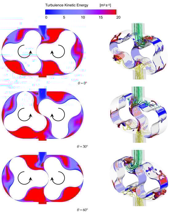
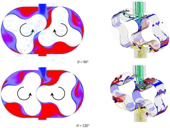
Figure 15.
Turbulent kinetic energy and three-dimensional flow field in the hydrogen circulation pump with the baseline rotor.
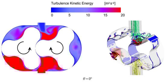
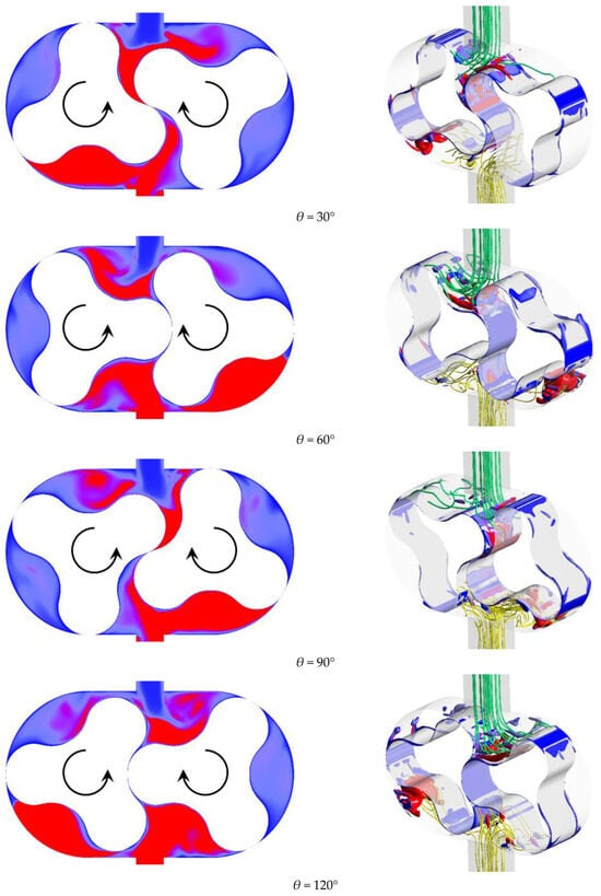
Figure 16.
Turbulent kinetic energy and three-dimensional flow field in the hydrogen circulation pump with the optimized rotor.
According to Figure 15 and Figure 16, the axial-plane distribution of TKE at various rotor angles θ reveals significant differences between the baseline and optimized rotors. For the baseline rotor, the TKE distribution exhibits strong disorder and high energy dissipation characteristics across all observed angles. At θ = 0°, high-TKE regions are widely distributed along the chamber boundaries and clearances where energy is extensively dissipated in the form of turbulence. As the angle increases to θ = 30°, although the location of high-TKE regions shifts due to rotor rotation, the overall area remains largely unchanged. At θ = 60° and 90°, the TKE distribution undergoes complex fluctuations in response to the changing meshing positions, reflecting the random nature of energy transfer within the flow field. This randomness impairs the efficiency of energy conversion into useful work, leading to considerable losses as TKE within disordered flows. In contrast, the optimized rotor demonstrates a more orderly and controllable TKE distribution across all rotational positions. At the initial angle of θ = 0°, the high-TKE zones are significantly reduced compared to the baseline case, confined primarily to localized regions near the rotor meshing surfaces and selected chamber walls. This indicates that the optimized profile effectively suppresses unnecessary flow disturbances in non-functional regions. As θ increases to 30° and 60°, the high-TKE zones maintain a “concentrated and structured” distribution pattern, with energy dissipation localized within essential shear and compression zones. Meanwhile, other areas exhibit significantly lower TKE levels, indicating that the optimized rotor effectively guides energy transmission along controlled paths and improves energy utilization efficiency. At θ = 90° and 120°, high-TKE regions migrate in a stable and predictable manner with rotor rotation, maintaining a consistent distribution pattern. This demonstrates the optimized profile’s superior capability in regulating energy transfer within the flow field, which contributes to the stable and efficient operation of the hydrogen circulation pump.
The three-dimensional vortex structures further highlight the contrast between the two rotors. For the baseline rotor, the vortex field is characterized by high levels of complexity, turbulence, and energy dissipation. At θ = 0°, large-scale vortex clusters dominate the domain, where vortices intertwine and merge to form intense dissipation zones. These vortex structures not only increase flow resistance but also continuously consume energy throughout the generation–breakdown–reformation cycles. As θ increases to 30°, the spatial configuration of the vortices changes, yet the disordered nature of the flow persists. The vortices become increasingly fragmented and dispersed, and multiscale vortex interactions further accelerate energy loss. At θ = 60° and 90°, the vortex field remains trapped in a chaotic cycle of “generation-dissipation-regeneration,” with frequent interactions between vortices, chamber walls, and meshing clearances intensifying flow losses. These observations reveal the baseline rotor’s limited ability to control vortex dynamics, thereby constraining flow stability and energy conversion efficiency. In contrast, the vortex structures of the optimized rotor exhibit clarity, order, and low energy dissipation. At θ = 0°, the vortices are organized as concentrated and controllable bundles with regular shapes that align well with the rotor profile, significantly reducing wall impingement and associated energy losses. As θ increases to 30° and 60°, the vortex structures evolve in an orderly manner along with the rotor motion. Their generation, development, and dissipation are guided by the rotor profile, exhibiting a pattern of “directional migration and orderly attenuation.” This prevents random vortex fragmentation and reduces unnecessary energy consumption. Even at θ = 90° and 120°, the vortex structures maintain their relatively simple and stable forms. The strength and extent of the vortices remain constrained by the rotor geometry, effectively suppressing vortex-vortex interference and minimizing additional energy losses. These characteristics collectively contribute to enhancing flow field stability and improving energy conversion efficiency.
In summary, the comparative analysis of TKE and three-dimensional vortex structures reveals that the optimized rotor offers significant advantages in flow regulation and energy efficiency over the baseline design. While the baseline rotor exhibits widespread turbulence, disordered energy dissipation, and chaotic vortex behavior, the optimized rotor achieves a more stable and concentrated energy distribution. Its streamlined profile effectively suppresses non-essential flow disturbances, confines high-energy zones to functional regions, and guides vortex evolution in a controlled and predictable manner. These improvements result in reduced flow resistance, minimized energy loss, enhanced flow stability, and improved overall performance of the hydrogen circulation pump.
5. Conclusions
A novel three-lobe rotor composed of variable-radius circular arcs was proposed in this study and compared with the conventional constant-radius arc rotor through numerical simulations. The results are presented as follows.
- (1)
- The optimized rotor demonstrates clear performance advantages over the baseline design. It increases the outlet mass flow rate by approximately 15.6%. These improvements stem from geometric refinements that lower flow resistance, suppress backflow, and enhance gas capture efficiency. Although the overall exhaust pressure pulsation trend remains largely unchanged, the optimized rotor introduces subtle modifications in peak magnitudes and phase timing.
- (2)
- The optimized rotor facilitates the formation of a more stable and streamlined velocity field within the pump chamber. In contrast to the baseline rotor, which exhibits localized velocity spikes and vortex formations, the optimized design suppresses non-essential flow disturbances and guides the gas along more orderly paths. This leads to reduced flow resistance, improved gas delivery uniformity, and decreased mechanical stress on internal components.
- (3)
- Comparative evaluations of TKE and three-dimensional vortex structures reveal that the optimized rotor significantly enhances energy regulation within the flow field. It confines high-energy regions to functionally necessary zones and ensures controlled, predictable vortex evolution. These improvements result in lower turbulence intensity, reduced energy losses, improved flow stability, and, ultimately, higher operational efficiency and reliability of the hydrogen circulation pump.
These improvements suggest that the optimized rotor design offers enhanced efficiency and reliability, making it highly promising for future hydrogen circulation and related applications. Its ability to increase flow throughput while maintaining stability could lead to significant energy savings and reduced mechanical wear, thereby extending pump service life and improving overall system performance in practical operations.
Author Contributions
Conceptualization, J.L. and Z.X.; Methodology, J.L., Z.X. and C.W.; Software, J.L. and C.W.; Validation, J.L. and Z.X.; Formal analysis, Z.X.; Investigation, J.L., Z.X. and R.W.; Resources, R.W.; Data curation, Z.X.; Writing—original draft preparation, J.L.; Writing—review and editing, J.L., Z.X. and R.W.; Visualization, J.L., Z.X. and R.W.; Supervision, J.L.; Project administration, J.L.; Funding acquisition, Z.X. All authors have read and agreed to the published version of the manuscript.
Funding
This research was funded by the Natural Science Foundation of the Jiangsu Higher Education Institutions of China, grant number 24KJB210020.
Data Availability Statement
The data presented in this study are available on request from the corresponding author.
Conflicts of Interest
Renrui Wang was employed by Bosch Automotive Products (Suzhou) Co., Ltd. Other author declare no conflict of interest.
References
- Chen, D.; Hu, H.; Wang, N.; Chang, C.-P. The impact of green finance on transformation to green energy: Evidence from industrial enterprises in China. Technol. Forecast. Soc. Change 2024, 204, 123411. [Google Scholar] [CrossRef]
- Manfren, M.; Gonzalez-Carreon, K.M.; Bahaj, A.S. Probabilistic modelling of seasonal energy demand patterns in the transition from natural gas to hydrogen for an urban energy district. Int. J. Hydrogen Energy 2024, 51, 398–411. [Google Scholar] [CrossRef]
- Ferrada, F.; Babonneau, F.; Homem-de-Mello, T.; Jalil-Vega, F. The role of hydrogen for deep decarbonization of energy systems: A Chilean case study. Energy Policy 2023, 177, 113536. [Google Scholar] [CrossRef]
- Lee, H.; Ahn, J.; Choi, D.G.; Park, S.Y. Analysis of the role of hydrogen energy in achieving carbon neutrality by 2050: A case study of the Republic of Korea. Energy 2024, 304, 132023. [Google Scholar] [CrossRef]
- Dincer, I.; Acar, C. Review and evaluation of hydrogen production methods for better sustainability. Int. J. Hydrogen Energy 2015, 40, 11094–11111. [Google Scholar] [CrossRef]
- Staffell, I.; Scamman, D.; Abad, A.V.; Balcombe, P.; Dodds, P.E.; Ekins, P.; Shah, N.; Ward, K.R. The role of hydrogen and fuel cells in the global energy system. Energy Environ. Sci. 2019, 12, 463–491. [Google Scholar] [CrossRef]
- Treffinger, P.; Brinner, A.; Schöll, R.; Friedrich, H.E. Fuel cell and hydrogen vehicles: State of the art and challenges for improved materials. In Proceedings of the Thermec 2006, PTS 1-5, Vancouver, BC, Canada, 4–8 July 2006; p. 1321. [Google Scholar]
- Selvaraj, V.; Arunkumar, K.; Thamil Magal, R.; Andal, V.; Alagar, M. A review on challenging of bridging technology between photocatalysts and fuel cell for generation of energy and production of hydrogen towards real time applications. Renew. Sustain. Energy Rev. 2025, 221, 115918. [Google Scholar] [CrossRef]
- Yap, T.; Tomomewo, O.S. A review of Techno-Economic Analysis and Density Functional Theory modeling of hydrogen fuel cells with Platinum-Based Catalysts for effective deployment in long-range electric vehicles. Int. J. Hydrogen Energy 2025, 137, 603–621. [Google Scholar] [CrossRef]
- Ding, H.; Dong, Y.; Zhang, Y.; Wen, C.; Yang, Y. Exergy performance analysis of hydrogen recirculation ejectors exhibiting phase change behaviour in PEMFC applications. Energy 2024, 300, 131563. [Google Scholar] [CrossRef]
- Tang, T.; Lu, C.; Xiao, C.; Chen, H.; Luo, M. Analysis of the degradation mechanism of high-power PEM fuel cells: End-plate effect due to hydrogen recirculation structure. Energy 2025, 333, 137340. [Google Scholar] [CrossRef]
- Yang, F.; Wang, T.; Deng, X.; Dang, J.; Huang, Z.; Hu, S.; Li, Y.; Ouyang, M. Review on hydrogen safety issues: Incident statistics, hydrogen diffusion, and detonation process. Int. J. Hydrogen Energy 2021, 46, 31467–31488. [Google Scholar] [CrossRef]
- Han, J.; Feng, J.; Chen, P.; Liu, Y.; Peng, X. A review of key components of hydrogen recirculation subsystem for fuel cell vehicles. Energy Convers. Manag. X 2022, 15, 100265. [Google Scholar] [CrossRef]
- Arabbeiki, M.; Mansourkiaei, M.; Ferrero, D.; Santarelli, M. Ejectors in Hydrogen Recirculation for PEMFC-Based Systems: A Comprehensive Review of Design, Operation, and Numerical Simulations. Energies 2024, 17, 4815. [Google Scholar] [CrossRef]
- Li, K.; Wang, C.; Li, J.; Wang, L.; Li, Z.; Zhang, C. Experimental Investigation into the Performance of PEMFCs with Three Different Hydrogen Recirculation Schemes. Inventions 2024, 9, 33. [Google Scholar] [CrossRef]
- Feng, J.; Xing, L.; Wang, B.; Wei, H.; Xing, Z. Effects of Working Fluids on the Performance of a Roots Pump for Hydrogen Recirculation in a PEM Fuel Cell System. Appl. Sci. 2020, 10, 8069. [Google Scholar] [CrossRef]
- Zhai, H.; Li, W.; Chu, X.; Mu, H.; Xu, Y. Research of the calculation formula for working clearance leakage flow of the hydrogen circulation pump. Front. Energy Res. 2024, 12, 1414926. [Google Scholar] [CrossRef]
- Xing, L.; Feng, J.; Chen, W.; Xing, Z.; Peng, X. Development and Testing of a Roots Pump for Hydrogen Recirculation in Fuel Cell System. Appl. Sci. 2020, 10, 8091. [Google Scholar] [CrossRef]
- Liang, X.; Kang, H.; Zeng, R.; Pang, Y.; Yang, Y.; Qiu, Y.; Tao, Y.; Shen, J. Impact of the Structural Parameters on the Performance of a Regenerative-Type Hydrogen Recirculation Blower for Vehicular Proton Exchange Membrane Fuel Cells. Sustainability 2024, 16, 1856. [Google Scholar] [CrossRef]
- Hwang, Y.-W.; Hsieh, C.-F. Study on high volumetric efficiency of the Roots rotor profile with variable trochoid ratio. Proc. Inst. Mech. Eng. Part C J. Mech. Eng. Sci. 2006, 220, 1375–1384. [Google Scholar] [CrossRef]
- Zhou, S.; Jia, X.; Yan, H.; Peng, X. A novel profile with high efficiency for hydrogen-circulating Roots pumps used in FCVs. Int. J. Hydrogen Energy 2021, 46, 22122–22133. [Google Scholar] [CrossRef]
- Yao, L.; Ye, Z.; Dai, J.S.; Cai, H. Geometric analysis and tooth profiling of a three-lobe helical rotor of the Roots blower. J. Mater. Process. Technol. 2005, 170, 259–267. [Google Scholar] [CrossRef]
- Li, Y.; Li, W.; Ji, L.; He, S.; Huang, Y.; Li, S.; Zhai, H.; Pu, W.; Li, X. Analysis of internal flow characteristics in hydrogen circulation pump with variable trochoid ratio profile. Int. J. Hydrogen Energy 2024, 61, 1429–1445. [Google Scholar] [CrossRef]
- Bhuyan, P.; Ghosh, S. Performance prediction of Roots blower based on shape of the rotor-profile using FVM with adaptive mesh redistribution technique and GA-tuned neural network. J. Braz. Soc. Mech. Sci. Eng. 2019, 41, 433. [Google Scholar] [CrossRef]
- Zhai, H.L.; Li, W.; Ji, L.L.; Awais, M.; Li, J.W.; Li, S. Profile Design and Performance Research of Hydrogen Circulation Pump in Fuel Cell System. Mechanika 2022, 28, 283–293. [Google Scholar] [CrossRef]
- Li, D.; He, Z.; Sun, S.; Wang, C.; Chen, W.; Xing, Z. Development and analysis of novel six-lobe helical rotors for hydrogen fuel cell vehicle roots blowers. Int. J. Hydrogen Energy 2021, 46, 30479–30493. [Google Scholar] [CrossRef]
- Wang, W.; Yan, D. Design of a circular-arc and variable-extended-cycloid rotor profile for hydrogen circulation pumps. Int. J. Hydrogen Energy 2024, 91, 458–469. [Google Scholar] [CrossRef]
- Ali, I.; Hussain, T.; Unar, I.N.; Kumar, L.; Ahad, I.U. Turbulence model study for aerodynamic analysis of the leading edge tubercle wing for low Reynolds number flows. Heliyon 2024, 10, e32148. [Google Scholar] [CrossRef]
- Asnaghi, A.; Svennberg, U.; Bensow, R.E. Evaluation of curvature correction methods for tip vortex prediction in SST k−ω turbulence model framework. Int. J. Heat Fluid Flow 2019, 75, 135–152. [Google Scholar] [CrossRef]
- Chang, H.; Yang, J.; Wang, Z.; Peng, G.; Lin, R.; Lou, Y.; Shi, W.; Zhou, L. Efficiency optimization of energy storage centrifugal pump by using energy balance equation and non-dominated sorting genetic algorithms-II. J. Energy Storage 2025, 114, 115817. [Google Scholar] [CrossRef]
- Du, Y.; Shu, B.; Gao, Z.; Nie, S.; Ma, R. On the Correction of k-ω SST Turbulence Model to Three-Dimensional Shock Separated Flow. In Proceedings of the 5th China Aeronautical Science and Technology Conference, Wuzhen, China, 2 November 2021; pp. 373–384. [Google Scholar]
- Kumar, A.; Bharti, R.P. Assessment of RANS-based turbulence models for isothermal confined swirling flow in a realistic can-type gas turbine combustor application. J. Comput. Sci. 2024, 81, 102362. [Google Scholar] [CrossRef]


Disclaimer/Publisher’s Note: The statements, opinions and data contained in all publications are solely those of the individual author(s) and contributor(s) and not of MDPI and/or the editor(s). MDPI and/or the editor(s) disclaim responsibility for any injury to people or property resulting from any ideas, methods, instructions or products referred to in the content. |
© 2025 by the authors. Licensee MDPI, Basel, Switzerland. This article is an open access article distributed under the terms and conditions of the Creative Commons Attribution (CC BY) license (https://creativecommons.org/licenses/by/4.0/).