Abstract
Layout design is the process in which industrial robots and other manufacturing components are positioned within a manufacturing system so that the intended operations can be handled appropriately. The traditional layout design process presents several challenges. It involves numerous iterations of testing different manually generated manufacturing layouts, requiring extensive trial and error to achieve an optimal solution. This process is highly time-consuming and demands significant expertise and cognitive effort from the designer. Within this publication, a flexible, scalable, and efficient function-block-based solution is presented for the optimization of manufacturing system layouts, especially in the field of multi-robot cells in two different use cases: one in additive manufacturing and one in jig-less welding. The findings showcase that the methodology followed enabled the efficient allocation of industrial robots in a workspace, minimizing the cognitive effort required in comparison to the traditional manual trial-and-error layout design procedure.
Keywords:
multi-robot cell; layout optimization; reachability; dexterity; stiffness; DED-Arc; jig-less welding 1. Introduction
Recent advancements in robotics and automation have resulted in the increased integration of advanced robotic systems in the manufacturing industry. Multi-robot manufacturing cells, particularly those incorporating cooperative and collaborative robots, can increase the efficiency, precision, and flexibility of manufacturing systems. In return, this results in substantial cost savings, lower lead times, and efficient adaptation to short- and medium-term demand fluctuations [1]. A notable example of these advantages can be observed in jig-less welding setups, which provide enhanced accessibility and improved productivity, especially in the case of intelligent multi-robot setups, in comparison with traditional jig-based ones, whether manual or automated. However, in order to handle the intended manufacturing operations and accomplish them appropriately, all the components comprising the cell have to be positioned correctly. The manufacturing operations can range from simple assembly tasks to complex machining and additive manufacturing (AM) processes. As an example, metal AM, such as Directed Energy Deposition (DED), is making important steps toward its adoption as a valid production alternative because it often offers similar or better material properties than parts made with traditional processes, such as casting, especially in repair applications [2]. Additionally, one of the most distinctive benefits of AM processes is their ability to produce lightweight, freeform parts with improved manufacturability achieved through optimization procedures like orientation [3,4]. However, the correct placement of robots is crucial for successfully executing calculated toolpaths, ensuring a smooth manufacturing process and preserving the part’s manufacturability.
The process in which industrial robots and other manufacturing components are allocated at specific positions inside a cell is called layout design [5]. The traditional layout design process poses a lot of challenges, as it involves numerous iterations of testing different manually generated robot layouts, requiring extensive trial and error to achieve an optimal solution. Additionally, this process is highly time-consuming and demands significant expertise and cognitive effort from the designer, which in the end is difficult and mentally overwhelming for humans.
2. Related Works
A large number of approaches and methodologies have been published aiming to solve the cell layout problem, especially in multi-robot systems performing assembly tasks. The majority of these studies utilize multi-objective algorithms to improve the layout, as this problem requires the optimization of two or more parameters simultaneously. Suemitsu et al. [6] proposed an approach for the layout optimization of multi-robot manufacturing systems using a multi-objective genetic algorithm. The layout design problem was formulated as a three-objective optimization problem, considering operation time (T), manipulability (W), and layout area (S). Task allocation and component positioning were simultaneously optimized. Lim et al. [7] examined and compared five nature-inspired algorithms to optimize the layout of robot workcells carrying out assembly tasks. All five algorithms were used to optimize the same three-objective problem. The layout area, operation time, and manipulability of the robot were the three measures optimized. Arkouli et al. [8] presented an innovative approach to workplace layout optimization in manufacturing, leveraging collaborative AI and immersive VR simulation to incorporate operator feedback, before the actual commissioning in two industrial use cases. In particular, they utilized an A*-based pathfinding algorithm to recommend layouts to minimize the travel distance of humans inside the workplace. Lim et al. [5] also developed a tool using multi-objective hybrid algorithms to solve layout problems in a multi-robot cellular manufacturing system, in which the robots were tasked to transfer parts from the part storage area to the assembly table. The optimal robot position is found through the optimization of certain parameters, including layout area, operation time, and robot manipulability. Tsarouchi et al. [9] proposed an approach for automatic workcell layout generation and task planning between human and robot resources. The approach takes into consideration multiple criteria, defined based on the user’s requirements to enable the selection of a good result regarding both the HRC layout and the task planning. Sánchez-Sosa et al. [10] proposed a multi-objective genetic algorithm for the layout of workstations in a single-robot robotic cell. The algorithm requires that the 2D dimensions of the robot’s base be specified. The objective function aims to minimize the work area while considering the interference of the stations and the robot base as constraints. Zhang et al. [11] proposed a layout optimization method for industrial robot automated production lines using an improved genetic algorithm. This approach was compared to both a standard design method and an optimization method based on a traditional genetic algorithm through a series of experiments. The results demonstrated a significant improvement in space utilization, a reduction in material handling distances within the workshop, and a more efficient production line layout. Qiu et al. [12] presented a method to concurrently optimize the layout and trajectory of a robot workcell to achieve energy-efficient, fast, and collision-free automation. The anchor points of the device and pose of the robot’s joints and end effector were parameterized by HTM with respect to the global frame. Furthermore, to simplify the justification of interference and collision, every device including the standby robot was enveloped by a cylinder. The method was validated on an automatic ultrasonic peening robot workcell, demonstrating a 58.8% reduction in energy consumption. Vosniakos et al. [13] introduced a method to optimize a milling robot’s position and pose where manipulability is highest using genetic algorithms.
An important aspect of the layout design process is understanding the robot’s working space and specifically defining the positions with the most relevant and feasible orientations.
The ability of a robotic manipulator to reach a target is defined as its ability to move its joints and links in free space in order for its hand to reach the given target [14]. A common solution to this problem is the construction of a reachability map for the robot. In general, a reachability map is a colored representation of the set of all positions and orientations that the robot’s end effector can achieve within its workspace [15,16]. Several research papers have been reported on robot base placement using reachability maps. Zacharias et al. [17] presented an approach for finding suitable placements of mobile robots for the execution of predefined workspace trajectories for tasks like opening doors or cupboards in environments such as kitchens. Many researchers have attempted to give a concrete definition of dexterity for robotic manipulators equipped with fingers performing grasping actions. Bicchi [18] defined dexterity as “(The) capability of changing the position and orientation of the manipulated object from a given reference configuration to a different one, arbitrarily chosen within the hand workspace”. Cao et al. [19,20] examined the feasible arm angle range as a crucial value to calculate the dexterity of a redundant manipulator arm of a humanoid robot. Then, the posture of the base of the manipulator is changed through the torso of the humanoid robot, allowing for the selection of an operation range with greater dexterity. Finally, the dexterity capability map of the working space of the manipulator is reconstructed. Quan et al. [21] proposed the Obstacle Avoidance Ability (OAA) index as a metric to measure the dexterity of a redundant manipulator during a grasping task at a specific tip pose. This index is calculated after generating the reachability map for each reachability sphere and is used to create a dexterity capability map of the manipulator, offering a new approach for pre-planning dexterous grasping tasks. Furthermore, in addition to the reachability criteria, the layout optimization of a robotic cell has also been addressed based on the robot’s stiffness, a metric that is considered in this work as well. Bikas et al. [22] proposed an approach for the optimization of a load-bearing robotic cell performing hybrid manufacturing, which is based on the robotic arm’s stiffness values generated by the involved manufacturing processes, subtractive and additive.
The aforementioned studies concerning cell layout optimization proposed solutions for the optimization of manufacturing system layout mostly in assembly lines, using multi-objective algorithms. These algorithms minimize the operation time, the layout area, and the system’s energy consumption to maximize the manufacturing system’s productivity. Assumptions concerning the trajectories, the parts dimensions, the operating sequence of the robots, the material flow, etc., and simplifications of the components’ working envelopes need to be made in advance to run the algorithms. Taking all the above into consideration, the approach of multi-objective algorithms cannot be replicated directly for applications of interest in this work, as the robot trajectories, and therefore the robot position and orientation during operation, highly depend on the product that is processed. In these applications, the products to be processed are not standardized, making any assumptions unreliable. The high variability of products means that any robot layout for such applications must be optimized based on kinematic and dynamic criteria, such as reachability, dexterity, and stiffness. The optimization process should aim to balance the abovementioned factors to provide the most effective overall solution to cover a wide range of robot trajectories and therefore allow a wide range of products to be processed.
Concerning reachability and the use of reachability maps for correct robot placement, previous approaches primarily focused on single-robot systems, and especially on mobile humanoid robots. These maps were used to determine suitable base placements for robots executing predefined trajectories and, in particular, grasping tasks. Moreover, while some of the studies introduced additional indices to measure a robot’s dexterity at specific points, they mainly apply to redundant manipulators.
After reviewing the aforementioned works, it was concluded that there is a gap in software tools able to optimize the layout design of a multi-robot cell performing manufacturing processes with respect to robot kinematics and dynamics criteria. The presented work focuses on addressing this gap by utilizing reachability maps to calculate the correct base placement of different robotic manipulators, taking into consideration reachability, dexterity, and stiffness criteria. The objective of this study was to develop an efficient, scalable, and automated method for optimizing robot placement within multi-robot manufacturing systems, reducing reliance on manual trial-and-error approaches. Additionally, the tool requires minimal user input —only the 3D CAD model of the multi-robot cell—and was developed with a function block programming language which facilitates the visualization of results and interconnection with external languages, such as Python. By validating the approach through real-world case studies in Directed Energy Deposition–Arc (DED-Arc) and jig-less welding applications, this work contributes a novel methodology that enhances efficiency, reduces design complexity, and ensures optimal robot positioning for diverse manufacturing tasks. In comparison with the traditional design process, it saves time, is simple to use as no special expertise and knowledge on robotics is required, and can be easily scaled and reproduced for other manufacturing processes.
The rest of the paper is organized as follows. Section 3 describes the methodology step by step. Section 4 presents the two case studies: the DED-Arc cell and the jig-less welding cell. Section 5, outlines the results from each use case. Finally, in Section 6, the discussion on results and the conclusions, future steps of the proposed work are presented.
3. Materials and Methods
3.1. Architecture
The entire architecture is pictured below in Figure 1. The layout optimization process begins with importing the robot cell in STEP format (.STP). The STEP files of the multi-robot cell must be of high quality, so that the presented tool works seamlessly. Additionally, concerning the creation of the multi-robot system CAD file, all CAD software is acceptable as long as it exports files in .STP format. Reachability, dexterity, and stiffness maps are then generated through external scripts in Python 3.11 and Matlab 24.1 by defining the links of each robot and its corresponding working envelope. Potential collisions between robots or other components of the cell may also be considered. From an implementation perspective, the working envelope of each robot is limited by excluding volumes that intersect with potential collisions. A function was set to select the CAD files that are considered as collisions. As soon as the setup of the multi-robot cell is completed, the optimization problem to be solved may be defined through the utilization of function blocks. The results can therefore be calculated, exported, and visualized.
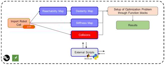
Figure 1.
Layout optimization architecture.
3.2. Software Implementation
The function-block-based software implementation was developed within the Rhinoceros [23] and Grasshopper [24] environments. This software was chosen after a thorough comparison with typical programming languages (Python 3.11, C#, etc.) and function block programming. Traditional programming languages often lack a built-in user interface, offer limited libraries for 3D geometry operations, such as union, difference, and intersection, and require high expertise to develop tools incorporating these functions from scratch. In contrast, function block programming languages, particularly Rhinoceros 3D and Grasshopper 3D, combine the benefits of a CAD environment with the ability to manipulate various geometries—ranging from points to BReps (Boundary Representations), meshes, and surfaces—using integrated block components. Additionally, the selected software provides an affordable solution and supports the development and implementation of Python and C# scripts. Additionally, external scripts, primarily written in Python, were utilized to facilitate and accelerate computationally intensive parts of the tool. Finally, it is essential to highlight that the selection of software was based on all the abovementioned reasons, and it is beyond the scope of this work to provide a detailed software comparison or conduct a market analysis.
3.3. Robot Definition
The first step of the workflow is to import the multi-robot cell in .STP format in the Rhinoceros environment. Following, each specific map that needs to be calculated (reachability, dexterity, stiffness) for each robot has to be defined. More specifically, the user selects the robot’s links (these could also be imported randomly) in the Rhino viewport and presses the toggle button (Block 1, Figure 2) to import them into the Grasshopper script. Then, the links are sorted automatically from bottom to top (from base to flange) by a custom Grasshopper script (Block 2, Figure 2). More specifically, the geometrical centers of the robot’s links are calculated, and the link with the center closer to the base plane is defined as the robot’s base. Then, the other links are sorted based on the distance of each link’s geometrical center from the robot’s base. Following this, the sorted robot links are imported into a custom Grasshopper script (Block 3, Figure 3), which extracts the Denavit–Hartenberg (DH) parameters of the robot. The robot’s links, starting from base to flange, are grouped sequentially by two in order to locate their intersection points, which are necessary for calculating the DH parameters. The automatic extraction of DH parameters follows the methodology presented in [25]. The final step for the process of robot definition is to import the robot’s joint limits using the sliders (Block 4, Figure 4).
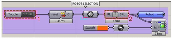
Figure 2.
Robot link selection and sorting in Grasshopper.
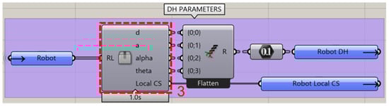
Figure 3.
DH parameters automatic extraction in Grasshopper.
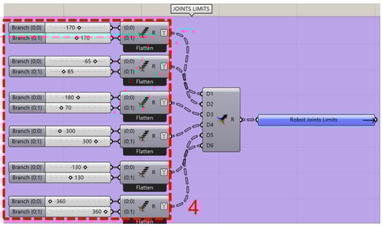
Figure 4.
Joint limit sliders in Grasshopper.
3.4. Robot Working Envelope Definition
As soon as all the robots are defined, the next step of the workflow involves defining the relative working envelopes, where the calculation of any map needs to be generated. The user first selects the CAD of the working envelope within the Rhino viewport and presses the toggle button (Block 1, Figure 5) to import it into the Grasshopper script. The working envelope is then converted from a BRep to a mesh to be voxelized by a custom Grasshopper script (Block 2, Figure 6). The voxel size, measured in millimeters, is defined by the user using the slider (Block 3, Figure 6). The center points of the voxels, which are initially in the world coordinate system, must be transformed into the robot’s local coordinate system. This transformation is accomplished using Block 4, as seen in Figure 7.
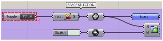
Figure 5.
Space selection in Grasshopper.
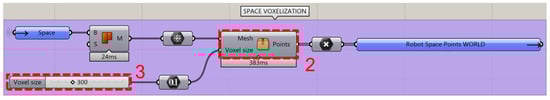
Figure 6.
Space voxelization in Grasshopper.

Figure 7.
Point transformation in Grasshopper.
3.5. End Effector Definition
Next, the end effector must be defined (in the context of this study, the end effectors are welding torches), specifically its transformation matrix. This matrix describes the rotations and translations required for a geometry to move from one coordinate system to another, in this case, from the flange frame to the welding torch’s tip frame. Rhino provides a built-in function to calculate the transformation matrix between two planes [26], which can be easily executed through a Python script, as shown in Figure 8. The transformation matrix is then inverted for the calculation of inverse kinematics based on the following equations:
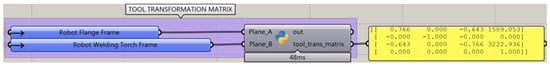
Figure 8.
Tool transformation matrix using Python in Grasshopper.
3.6. Reachability and Dexterity Map Generation
The reachability and dexterity map generation architecture are presented in Figure 9. The section marked by a green dashed line boundary in the schematic refers architecturally to the steps described in Section 3.4 and Section 3.5.
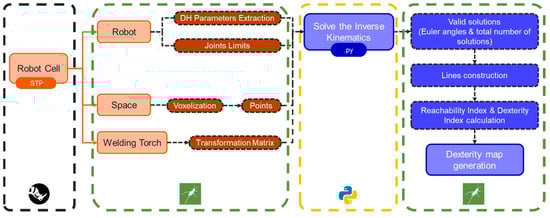
Figure 9.
Dexterity map architecture.
First, the DH parameters and the joint limits of the robot, along with the transformed points of the voxelized working envelope and the inverted transformation matrix of the end effector, are imported into a custom Python script that exports the inverse kinematics solutions of the robot for specific frames of each point of the envelope. Posture variation is explored during the iteration process, performed through the Python script, to minimize an error metric (difference between current and desired pose), aiming to find the optimal robot pose for each frame. The frames are generated by considering all possible combinations of Euler angles (ZYX), using an angle step size defined by the user. The results for each point consist of the valid solutions’ Euler angles and the total number of valid solutions. The Euler angles are then used to rotate the z axis of the base plane and construct the valid solutions as lines, as shown in Figure 10. This line construction allows for the calculation of the reachability index (D1) and the dexterity index (D2). The length of the line is equal to the voxelization distance of the space. However, the length of the line does not play any vital role, as the values required for the calculation of the reachability and dexterity indices are normalized and only exist for computation purposes.
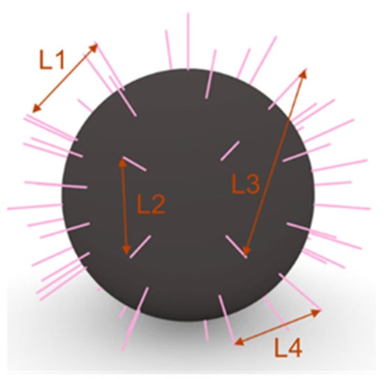
Figure 10.
Representation of the valid solutions and the line distances on a sphere for the calculation of the reachability and dexterity indices.
The reachability index is calculated using Equation (3), where R is the number of reachable poses and N is the total number of discretized poses in the sphere. This index indicates the robot’s ability to reach a point with different poses. The dexterity index is calculated by Equation (4), where S is the shortest average line distance (S) among all points and L is the average distance of the lines representing the valid solutions. This measure is crucial for manufacturing processes, as it indicates the robot’s ability to move around a point with precise and smooth movements. Finally, the index that characterizes the spheres of the dexterity map is equal to the average of the two indices (Equation (5)).
Finally, after calculating the total index of each point, the different values are used to create a color gradient and generate the dexterity map of the robot.
3.7. Stifness Map Generation
In the context of this paper, the stiffness refers to the capacity of each robot to withstand unidirectional forces. These forces may represent payloads during manipulation, the resistance of the material during robot machining, welding forces during jig-less welding, and other factors. In this study, deformations of the robot links were disregarded, under the assumption that the robot would reposition itself before any deformation occurred. The methodology used to calculate stiffness is presented in Figure 11.
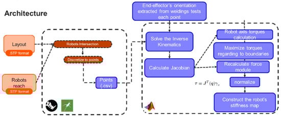
Figure 11.
Stiffness calculation architecture.
First, the direction of the stiffness to be maximized needs to be decided. It could also be calculated with an approach similar to that presented in the previous section to obtain a metric for a matrix of discretized orientations, which would have been averaged later. However, the critical direction of the applied force is usually found through trial and error, testing, or simulation, such as FEM modeling, resulting in a more efficient and cost-effective approach.
Then, the Jacobian is calculated to convert the joint torques to forces exerted by the end effector [27], as shown in Equation (6), where τ represents joint torques, is the transpose of the Jacobian matrix, and is the force vector at the end effector.
Next, a trivial optimization problem is solved to calculate the maximum force that the robot can apply in each position without exceeding the maximum torques in the joints. And finally, these metrics are normalized.
4. Case Studies
In order to validate the proposed methodology, two case studies of multi-robot cells were examined: one performing DED-Arc for repairing existing, large-scale, and high-value components and one performing jig-less welding.
4.1. DED-Arc Cell Case Study
The multi-robot DED-Arc cell consisted of a six-degrees-of-freedom (6-DoFs) industrial robot, which was responsible for gripping the DED-Arc torch and executing the DED-Arc process. Additionally, a 2-DoF rotary table with 250 kg of payload was utilized to position and withhold the workpiece to be repaired. Finally, a collaborative robot was utilized for 3D scanning and coordinate referencing operations. The initial layout of the DED-Arc cell is presented in Figure 12.
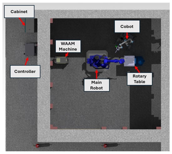
Figure 12.
Initial layout of DED-Arc cell.
The dexterity of a robot performing a manufacturing process that involves complex and continuous toolpaths is significantly more important compared to that of a robot conducting assembly operations. Therefore, to define the area with the highest level of dexterity and reachability of the YASKAWA GA50 robot and accurately position it in relation to the rotary table (workpiece area), the layout optimization tool was used. Two DED-Arc torch placements were tested: one with the DED-Arc torch positioned concentric to the flange and one placed non-concentrically, as seen in Figure 13a and 13b, respectively. The non-concentric option was designed with an offset of 180 mm to make the optimization process more challenging, given the high possibility of this distance being shortened.
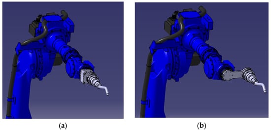
Figure 13.
DED-Arc robot with welding torch placed (a) concentrically and (b) non-concentrically.
For computational efficiency, the maximum workspace was calculated as the intersection of the robot’s workspace and the rotary table’s workspace. The robot’s reachability and dexterity were evaluated within a 2D planar intersection, as this is symmetrical around the robot’s first rotational axis (around robot’s base). Different placements were assessed through a step-by-step iterative process, moving the table within predefined indexed limits by 30 mm increments.
4.2. Jig-Less Welding Cell Case Study
The jig-less welding cell was composed of two industrial 6-DoF robots: one collaborative 6-DoF robot and a Fronius arc-welding subsystem to carry out gas metal arc welding (GMAW) processes. Additionally, a 2-DoF rotary table was also present in the cell. Although this rotary table would not be used, it needed to be considered for collision avoidance. The two industrial robots were responsible for clamping the parts that were to be welded, without the need for jigs. The welding process was executed by the collaborative robot, as a higher degree of flexibility was provided to the robot cell. The 3D CAD model of the multi-robot jig-less welding cell is pictured in Figure 14.
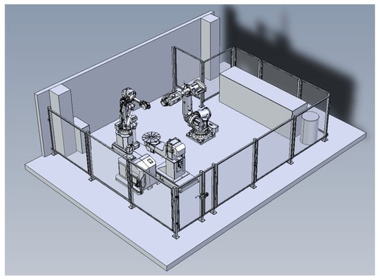
Figure 14.
Initial layout of jig-less welding robot cell.
Although the configuration of the multi-robot cell does not leave much room for layout optimization, as the robots’ bases cannot be moved, optimization of the working envelope was performed. The idea behind this optimization was to find the optimal position in which the welding process could be carried out to maximize the stiffness of the manipulation robots and the dexterity of the three robots, without moving their bases. External forces were only expected to affect the manipulator robots of the jig-less welding cell. Consequently, for the collaborative robot, the stiffness map was not calculated. The optimization analysis was performed inside the working envelope that occurred from the intersection of the working envelopes of the three robots, the two robotic manipulators and the collaborative robot. The individual working spaces and their intersection are shown in Figure 15a and 15b, respectively.
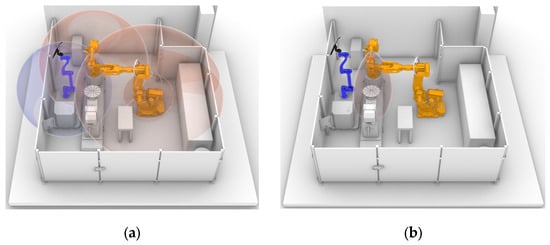
Figure 15.
(a) Representation of the working spaces of the three robots of the jig-less welding cell inside Rhino. (b) Representation of the intersection of the working spaces of the robots of the jig-less welding cell inside Rhino.
5. Results
In this section, the results of the two case studies described in Section 4 are presented and analyzed. The results of each case study are as follows.
5.1. DED-Arc Cell Case Study
The same workflow was followed for both torch placements. First, the robot was selected, its Denavit–Hartenberg (DH) parameters were calculated, and its joint limits were defined. Next, the robot’s working space was defined. For each torch placement, the tip and corresponding tip frame were defined. These tip frames were then used to calculate their respective transformation matrices. The rotary table working space was also defined. The optimization procedure falls under the following two criteria:
- Maximize the available working space of the DED-Arc robot and rotary table.
- Maximize the reachability and dexterity (total index Dtot) within the defined working space.
For the first criterion, an index named intersection volume (IV) was utilized, which is the volume that occurs as result of the intersection of the robot’s working space with the rotary table’s working space when the robot occupies a certain position in space and is measured in mm3. Regarding the second criterion, an index named Volume Dtot (VDtot) is utilized and is equal to the average value of the total indices of the points of the discretized space inside the intersection volume. It has no units as the index is normalized.
The initial positions of the robot and the rotary table are shown in Figure 16. Both pieces of equipment were aligned along the vertical axis, with a horizontal distance of 1140.5 mm between them. In order to find the optimal robot base placement in relation to the rotary table, the robot was moved to each point of its discretized space, and the intersection volume and the Volume Dtot (VDtot) were calculated.
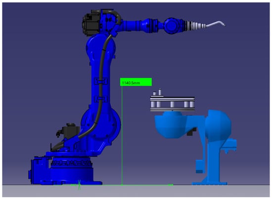
Figure 16.
Initial position of DED-Arc main robot and rotary table.
In Table 1, the best results from the optimization procedure are presented for the concentric torch placement as regards the vertical and horizontal movement of the robot in relation to the rotary table, assuming it was stable. In Table 2, the results for the non-concentric torch placement are presented.

Table 1.
Best results from the optimization process of the robot with the concentric torch placement including only the rotary table.
Table 2.
Best results from the optimization process of the robot with the non-concentric torch placement including only the rotary table.
In Figure 17, the results for the optimal solutions are visualized in (a) for the concentric torch placement and in (b) for the non-concentric one.
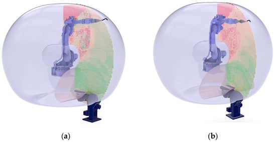
Figure 17.
Optimal robot position in relation to the rotary table with (a) concentric torch placement and (b) non-concentric torch placement.
For the concentric configuration, the results indicated that the DED-Arc robot should be lifted 1230 mm on the vertical axis, while the horizontal distance should be minimized to 290 mm. For the non-concentric configuration, the results indicated that the DED-Arc robot should be lifted 1200 mm on the vertical axis, while the horizontal distance should be minimized to 260 mm. The initial results from the first optimization showcased that similar solutions could be attained with both torch placements. Although they are optimized, they limit the scalability of the cell for manufacturing parts, except for the nominal position on the rotary table. This includes cases where larger parts may need to be positioned on the floor. Therefore, a re-iteration was conducted to evaluate the layout of the rotary table, with an additional workpiece placed near the robot on the floor, as presented in Figure 18.
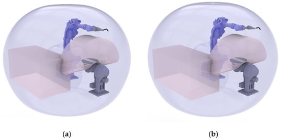
Figure 18.
Rotary table and floor workpiece evaluation: (a) concentric torch placement; (b) non-concentric torch placement.
Following a weight criterion of 70% for the results for the rotary table, and 30% for the effect on the workpiece positioned on the floor, the following optimal locations were identified. First, the optimal position was calculated for the concentric torch placement, which was lifting the robot 750 mm on the vertical axis from the ground, while the horizontal distance was maximized at 250 mm, as presented in Table 3. Then, the optimal position was calculated for the non-concentric torch placement, which was lifting the robot by 400 mm on the vertical axis and maximizing the horizontal distance at 370 mm, as presented in Table 4. The results for the optimal solutions are visualized in Figure 19 for both torch placements.
Table 3.
Best results from the re-iteration optimization process of the robot with the concentric torch placement, including the rotary table and the floor workpiece.
Table 4.
Best results from the re-iteration optimization process of the robot with the non-concentric torch placement, including the rotary table and the floor workpiece.
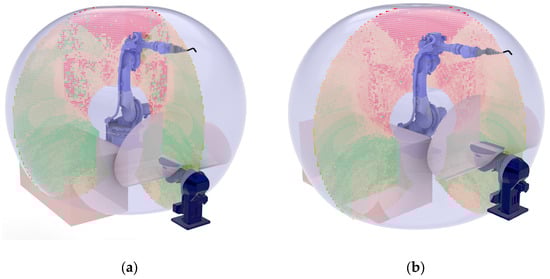
Figure 19.
Optimal robot position after the re-iteration with the floor workpiece with (a) concentric torch placement and (b) non-concentric torch placement.
Based on the results above, we decided to proceed with a 400 mm lift on the vertical axis, ensuring adequate space from the ceiling for safety reasons. A re-iteration within the 400 mm vertical lift was conducted to calculate the horizontal distance. The results are summarized in Table 5 and Table 6 for the concentric and the non-concentric torch placement, respectively.
Table 5.
Best results from the re-iteration optimization process of the robot with the concentric torch placement, including the rotary table and the floor workpiece at 400 mm vertical lift.
Table 6.
Best results from the re-iteration optimization process of the robot with the non-concentric torch placement including the rotary table and the floor workpiece at 400 mm vertical lift.
The best solutions from each iteration and optimization category to fulfil all the abovementioned requirements are presented in Table 7.
Table 7.
Optimal solutions by optimization category, including floor workpiece.
Therefore, the industrial robot was moved 400 mm on the vertical axis, and the horizontal distance was maximized at 370 mm. The results for both solutions are presented in Figure 20a,b. Lower-level dexterity points located in the higher heights could be mitigated by using the two extra DOFs from the rotary table, by repositioning the workpiece through tilting and rotating it to a higher dexterity point through the trajectory generation (CAM—Computer-Aided Manufacturing) software.
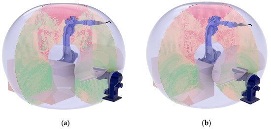
Figure 20.
Final robot position in relation to the rotary table and the floor workpiece with (a) concentric torch placement and (b) non-concentric torch placement.
The collaborative robot that is responsible for the auxiliary operations should be able to reach the workpiece area in order to conduct the needed operations, but the dexterity is not critical. Additionally, the cobot should be positioned in a way to not interfere with the operation of the industrial robot. The reachability of the cobot should be sufficient to access the workpiece, even by evaluating it through the working envelopes; however, it must be elevated along the vertical (Z) axis to bring its base closer to the workpiece plane. Specifically, the cobot requires a base lift of approximately 800–900 mm. To ensure flexibility in positioning along the Z axis, the cobot was designed with an automatic adjustable base for its height to ensure the appropriate handling of different workpieces of different sizes. Furthermore, the cobot must be positioned close to the rotary table in the XY plane. This creates practical problems, such as when loading and unloading workpieces. Moreover, there are safety concerns, as the industrial robot could potentially collide with the system while performing its processing tasks. Therefore, we decided to design a movable base through caster wheels, so that the cobot can be freely moved in the processing area. Moreover, the caster wheels have a leveling mechanism, which will help with potential floor abnormalities.
5.2. Jig-Less Welding Cell Case Study
First, the reachability/dexterity index of the collaborative robot was calculated (normalized from 0 to 1). The results are presented in Figure 21. The maximum value was 1.00, while the minimum value was 0.34. The points with a reachability/dexterity index above 0.7 are presented in Figure 22.
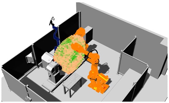
Figure 21.
Colored representation of the total index results in the discretized working space for welding cobot (DOOSAN H2017).
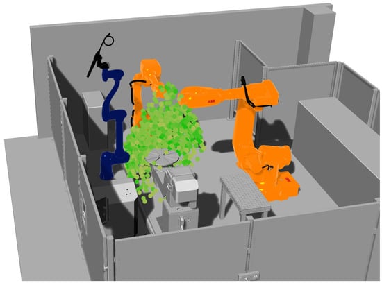
Figure 22.
Colored representation of the total indices with values above 0.7 in the discretized working space for welding cobot (DOOSAN H2017).
It may be understood that the cobot in its current location presents several points and locations where sufficient reachability and dexterity exist. Given the results, we decided to follow the following criteria for the optimisation of this layout:
- A 40% criterion for the dexterity of the cobot.
- A 50% criterion for the stiffness of the low-payload manipulator robot.
- A 10% criterion for the stiffness of the high-payload manipulator robot.
The stiffnesses for both robots, similarly to the dexterity calculations, were normalized from 0 to 1, as regards the minimum and the maximum values. The final results are illustrated in ranges of color-mapped points in Table 8 and visualized in Figure 23a,b.
Table 8.
Jig-less welding case study optimization results.
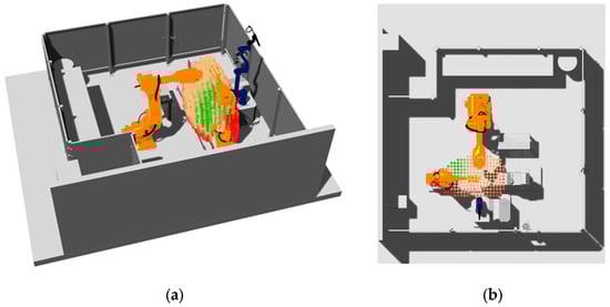
Figure 23.
Normalized optimization indices for jig-less welding cell: (a) perspective view and (b) top view.
And the results are illustrated next.
Based on the results, the optimal welding position was identified as the area adjacent to the low-payload manipulator robot when it is oriented toward the high-payload manipulator robot. This conclusion is intuitive, as this position maximizes the low-payload robot’s stiffness. Indeed, the primary criterion for this determination was the maximization of this robot’s stiffness.
6. Discussion
A methodology and a tool have been presented for optimizing the layout design of multi-robot cells performing manufacturing processes, based on function block programming and external scripts for calculating the kinematic and dynamic criteria of the robots. The optimization process considers the reachability, dexterity, and stiffness criteria of the robots within the cell, generating a map of colored spheres to indicate areas of low and high performance. The methodology was tested on two multi-robot cells: one performing DED-Arc and one conducting jig-less welding. In the first case study, the robotic manipulator was repositioned relative to the rotary table to maximize dexterity and reachability. In the second case study, the optimal welding position was identified to maximize the stiffness of the manipulation robots and the dexterity of all three robots without altering their base positions.
The use of reachability/dexterity maps presented certain limitations, primarily due to the computational intensity of the process of calculating the inverse kinematics solutions required for the plethora of points and frames in the working envelope to achieve high-resolution results. For example, calculating the full reachability map analytically for a discretization distance of 30 mm and an angle step size of 30°, using a PC including 64 GB RAM, an RTX 3060 GPU, and an i7-13700 @ 2.1 GHz CPU, would require approximately 20 h. For this reason, the robot’s reachability and dexterity were evaluated within a 2D planar intersection, with the assumption that it was symmetrical around the robot’s first rotational axis (around robot’s base), requiring only 1 h of processing.
The software tools used to implement the function block programming were Rhinoceros 3D and Grasshopper 3D due to their capability to combine a visualization environment and a simple visual programming language capable of handling 3D geometries in a simple-to-use manner with a low cost. Furthermore, these allow the user to embed their own custom code if needed (using Python or C#). The implementation of the proposed method could also be tested for development using other software tools. The use of a programming language that includes 3D geometry libraries is also proposed.
The traditional layout design process, characterized by numerous iterations and extensive trial and error, has been significantly streamlined. The methodology and the software tool developed enabled the efficient allocation of industrial robots and manufacturing components within a multi-robot cell, demonstrating improved performance in handling the desired tasks. As a result, the cognitive effort and expertise required from designers has been reduced, leading to more reliable and effective manufacturing systems. However, it should be noted that decisions can also be made manually in simpler cases, such as the cobot positioning of DED-Arc use case, where evaluating the interfering working envelopes was sufficient to make the appropriate design choices.
Future work will aim to evaluate the proposed methodology in other manufacturing processes, including those involving robots with different configurations, as well as different robot types and degrees of freedom. Additionally, future work will aim to evaluate the development of a generalized framework to standardize the handling of multi-robot manufacturing system optimization problems for easier and more systemic replicability of results.
Author Contributions
Conceptualization, P.S. and C.P.; methodology, C.P. and M.A.T.; software, M.A.T.; validation, C.P., I.S., J.R.V., E.G.I. and P.L.; writing—original draft preparation, M.A.T. and C.P.; writing—review and editing, P.S. and I.S.; supervision, P.S. All authors have read and agreed to the published version of the manuscript.
Funding
This research was partially funded by COROB (cooperative robotics powered by AI and data for flexible production cells) project, which is cofunded by the EU’s Horizon Europe program under grant agreement number 101120640. However, the views and opinions expressed are those of the author(s) only and do not necessarily reflect those of the European Union. Neither the European Union nor the granting authority can be held responsible for them. This work has received funding from the Swiss State Secretariat for Education, Research, and Innovation (SERI).
Data Availability Statement
The original contributions presented in this study are included in the article. Further inquiries can be directed to the corresponding author(s).
Conflicts of Interest
Authors Iñaki Sainz and Jonatan Rodriguez were employed by the company LORTEK Technological Centre, Basque Research and Technology Alliance (BRTA), author Panagiotis Lagios was employed by the company Gizelis Robotics and author Enrique Gil Illescas was employed by the company Grupo DGH, Parque Tecnológico. The remaining authors declare that the research was conducted in the absence of any commercial or financial relationships that could be construed as a potential conflict of interest.
Abbreviations
| Acronym | Definition | Description |
| DED-Arc | Directed Energy Deposition–Arc | Metal additive manufacturing process in which gas metal arc welding is used to fuse materials by melting as they are being deposited. |
| AM | additive manufacturing | Manufacturing technology based on layer-by-layer material deposition. |
| DED | Directed Energy Deposition | Metal additive manufacturing process in which focused thermal energy is used to fuse materials by melting as they are being deposited. |
| DH | Denavit–Hartenberg (Parameters) | A standardized set of four parameters (θ,d,a,α) used to define the relative transformation between consecutive links in a kinematic chain. |
| OAA | Obstacle Avoidance Ability | A metric used to evaluate a robot’s ability to avoid collisions while performing tasks. |
| FEM | Finite Element Method | A numerical technique used in engineering to analyze stress, deformation, and other physical behaviors of materials under load. |
| GMAW | gas metal arc welding | A welding process where an electric arc forms between a continuous wire electrode and the workpiece, melting the metals to join them. |
| DOF | degrees of freedom | The number of independent movements a robotic system or mechanical component can perform. |
| CAD | Computer-Aided Design | Software used to create, modify, and optimize 3D models for engineering and manufacturing applications. |
| CAM | Computer-Aided Manufacturing | The use of software to automate manufacturing processes, often converting CAD models into toolpaths for CNC machines or robots. |
| HRC | Human–Robot Collaboration | A concept in robotics where humans and robots work together in shared environments, often requiring safety and task coordination mechanisms. |
References
- Vaisi, B. A Review of Optimization Models and Applications in Robotic Manufacturing Systems: Industry 4.0 and Beyond. Decis. Anal. J. 2022, 2, 100031. [Google Scholar] [CrossRef]
- Stavropoulos, P. Additive Manufacturing: Design, Processes and Applications; Springer Briefs in Applied Sciences and Technology; Springer International Publishing: Cham, Switzerland, 2023; ISBN 978-3-031-33792-5. [Google Scholar]
- Bikas, H.; Terzakis, M.A.; Stavropoulos, P. Manufacturability-Based Design Optimization for Directed Energy Deposition Processes. Machines 2023, 11, 879. [Google Scholar] [CrossRef]
- Lianos, A.K.; Bikas, H.; Stavropoulos, P. A Shape Optimization Method for Part Design Derived from the Buildability Restrictions of the Directed Energy Deposition Additive Manufacturing Process. Designs 2020, 4, 19. [Google Scholar] [CrossRef]
- Lim, Z.Y.; Ponnambalam, S.G.; Izui, K. Multi-Objective Hybrid Algorithms for Layout Optimization in Multi-Robot Cellular Manufacturing Systems. Knowl.-Based Syst. 2017, 120, 87–98. [Google Scholar] [CrossRef]
- Suemitsu, I.; Izui, K.; Yamada, T.; Nishiwaki, S.; Noda, A.; Nagatani, T. Simultaneous Optimization of Layout and Task Schedule for Robotic Cellular Manufacturing Systems. Comput. Ind. Eng. 2016, 102, 396–407. [Google Scholar] [CrossRef]
- Lim, Z.Y.; Ponnambalam, S.G.; Izui, K. Nature Inspired Algorithms to Optimize Robot Workcell Layouts. Appl. Soft Comput. 2016, 49, 570–589. [Google Scholar] [CrossRef]
- Arkouli, Z.; Tompoulidis, I.; Dimitropoulos, N.; Michalos, G.; Makris, S. Collaborative AI & Immersive VR Simulation for Workplace Layout Optimization in Manufacturing Applications. Procedia CIRP 2024, 130, 336–341. [Google Scholar] [CrossRef]
- Tsarouchi, P.; Michalos, G.; Makris, S.; Athanasatos, T.; Dimoulas, K.; Chryssolouris, G. On a Human–Robot Workplace Design and Task Allocation System. Int. J. Comput. Integr. Manuf. 2017, 30, 1272–1279. [Google Scholar] [CrossRef]
- Sánchez-Sosa, R.-A.; Chavero-Navarrete, E. Robotic Cell Layout Optimization Using a Genetic Algorithm. Appl. Sci. 2024, 14, 8605. [Google Scholar] [CrossRef]
- Zhang, Y. Layout Design and Optimization of Industrial Robot Automated Production Line Based on Genetic Algorithm. J. Comput. Methods Sci. Eng. 2023, 23, 469–484. [Google Scholar] [CrossRef]
- Qiu, B.; Chen, S.; Gu, Y.; Zhang, C.; Yang, G. Concurrent Layout and Trajectory Optimization for Robot Workcell toward Energy-Efficient and Collision-Free Automation. Int. J. Adv. Manuf. Technol. 2022, 122, 263–275. [Google Scholar] [CrossRef]
- Vosniakos, G.-C.; Matsas, E. Improving Feasibility of Robotic Milling through Robot Placement Optimisation. Robot. Comput.-Integr. Manuf. 2010, 26, 517–525. [Google Scholar] [CrossRef]
- Ying, Z.; Iyengar, S.S. Robot Reachability Problem: A Nonlinear Optimization Approach. J. Intell. Robot. Syst. 1995, 12, 87–100. [Google Scholar] [CrossRef]
- Zacharias, F.; Borst, C.; Beetz, M.; Hirzinger, G. Positioning Mobile Manipulators to Perform Constrained Linear Trajectories. In Proceedings of the 2008 IEEE/RSJ International Conference on Intelligent Robots and Systems, Nice, France, 22–26 September 2008; pp. 2578–2584. [Google Scholar]
- Zacharias, F.; Borst, C.; Hirzinger, G. Capturing Robot Workspace Structure: Representing Robot Capabilities. In Proceedings of the 2007 IEEE/RSJ International Conference on Intelligent Robots and Systems, San Diego, CA, USA, 29 October–2 November 2007; pp. 3229–3236. [Google Scholar]
- Zacharias, F.; Sepp, W.; Borst, C.; Hirzinger, G. Using a Model of the Reachable Workspace to Position Mobile Manipulators for 3-d Trajectories. In Proceedings of the 2009 9th IEEE-RAS International Conference on Humanoid Robots, Paris, France, 7–10 December 2009; pp. 55–61. [Google Scholar]
- Bicchi, A. Hands for Dexterous Manipulation and Robust Grasping: A Difficult Road toward Simplicity. IEEE Trans. Robot. Automat. 2000, 16, 652–662. [Google Scholar] [CrossRef]
- Cao, B.; Sun, K.; Gu, Y.; Jin, M.; Liu, H. Workspace Analysis Based on Manipulator Pose Dexterity Map. In Proceedings of the 2018 3rd International Conference on Robotics and Automation Engineering (ICRAE), Guangzhou, China, 17–19 November 2018; pp. 166–170. [Google Scholar]
- Cao, B.; Sun, K.; Gu, Y.; Jin, M.; Liu, H. Humanoid Robot Torso Motion Planning Based on Manipulator Pose Dexterity Index. IOP Conf. Ser. Mater. Sci. Eng. 2020, 853, 012040. [Google Scholar] [CrossRef]
- Quan, Y.; Zhao, C.; Lv, C.; Wang, K.; Zhou, Y. The Dexterity Capability Map for a Seven-Degree-of-Freedom Manipulator. Machines 2022, 10, 1038. [Google Scholar] [CrossRef]
- Bikas, H.; Manitaras, D.; Souflas, T.; Stavropoulos, P. Process-Driven Layout Optimization of a Portable Hybrid Manufacturing Robotic Cell Structure. Eng 2024, 5, 918–931. [Google Scholar] [CrossRef]
- Rhinoceros 3D Software. Available online: https://www.rhino3d.com/ (accessed on 9 June 2023).
- Grasshopper 3D Software. Available online: https://www.rhino3d.com/features/#grasshopper (accessed on 29 November 2024).
- Chittawadigi, R.G.; Saha, S.; Kumar, S. Automatic Extraction of DH Parameters of Serial Manipulators Using Line Geometry. In Proceedings of the 2nd International Conference on Multibody System Dynamics, Stuttgart, Germany, 29 May–1 June 2012. [Google Scholar]
- Rhino3d Transform. PlaneToPlane Method. Available online: https://developer.rhino3d.com/api/rhinocommon/rhino.geometry.transform/planetoplane (accessed on 29 November 2024).
- Differential Kinematics and Statics. In Robotics: Modelling, Planning and Control; Siciliano, B., Sciavicco, L., Villani, L., Oriolo, G., Eds.; Springer: London, UK, 2009; pp. 105–160. ISBN 978-1-84628-642-1. [Google Scholar]
Disclaimer/Publisher’s Note: The statements, opinions and data contained in all publications are solely those of the individual author(s) and contributor(s) and not of MDPI and/or the editor(s). MDPI and/or the editor(s) disclaim responsibility for any injury to people or property resulting from any ideas, methods, instructions or products referred to in the content. |
© 2025 by the authors. Licensee MDPI, Basel, Switzerland. This article is an open access article distributed under the terms and conditions of the Creative Commons Attribution (CC BY) license (https://creativecommons.org/licenses/by/4.0/).