Abstract
The Stressed Mirror Polishing method (SMP) enables the high-quality and efficient fabrication of short-focus off-axis aspheres (SFOA) for overcoming difficulties arising from large asphericity, which makes the polishing tool unfitted for the mirror surface shape and produces mid- and high-frequency errors. However, there remains a lack of precise iterative loading methods and detailed analyses of loaded surface shape stability for processing SFOA through SMP. Therefore, a foundational analysis model for SMP was established, integrating mathematical theoretical modeling with a finite element analysis (FEA). Based on this model, an iterative loading strategy, based on the proportional relationship between the Zernike coefficients and the SMP-type surface shape error, was proposed to achieve a high dynamic range of >100, which is 10 times larger than the reported ones. Moreover, to guide the loading structure design and quantify the surface shape’s sensitivity to design parameters, both design of experiments (DOE) and radial basis function (RBF) methods had been used to ascertain the precision requirement of each force and the corresponding arm length at separated loading points, under the shape precision requirement of PV < 1 μm which coordinates with the ability of the Ion Beam Figuring (IBF) technique.
1. Introduction
The rapid advancement of modern optical engineering technology has ushered in an era of ultra-large apertures exceeding 4 m for both iteration-based and space-based optical telescopes. The United States reached a significant milestone in the 1990s with the 10 m aperture Keck Ⅰ&Ⅱ Telescope. Over the past decade, people have competitively pursued the development of three iteration-based optical telescopes with 30 m apertures: the United States’ Thirty Meter Telescope (TMT) and Giant Magellan Telescope (GMT), along with Europe’s Extremely Large Telescope (E-ELT). In the realm of space-based telescopes, the United States launched the James Webb Space Telescope (JWST) with a 6.5 m aperture in late 2021, and people have planned to deploy ~10 m aperture telescopes into geosynchronous orbit to achieve meter-level resolution for Earth observation. All of these large-aperture telescopes utilize a segmented primary mirror.
Advances in segmented mirror technology provide significant engineering benefits for space optical payloads, such as reducing the payload weight and lowering the requirements for optical fabrication conditions and launch vehicle capacity. Additionally, employing short-focus off-axis aspheres (SFOA) in the space optical system would enable a more compact optical structure, a wider field of view, lower central obstruction and would make it possible to launch more payloads in a single rocket for constructing large space telescopes and constellations.
SFOA mirrors used in space optics typically exhibit steeper curvatures, with asphericity about 10 to 100 times larger than traditional long-focus off-axis aspheres. This generates a series of problems for the optical fabrication of SFOA mirrors, such as low efficiency, high costs and undesirable medium–high-frequency errors. These issues are mainly attributed to the mismatch between various sub-aperture spherical polishing tools and the aspherical mirror surface. The traditional optical fabrication process, which usually involves grinding, polishing and a high-precision figuring technique like Ion Beam Figuring (IBF), typically takes 2 months to fabricate a Φ1500 mm mirror [1]. However, a new process through Stressed Mirror Polishing (SMP) assisted by IBF to the same mirror would result in a 50% reduction in time and a 50% save in cost.
It is anticipated that SMP technology would greatly improve the quality of optical fabrication. The principle of this technology involves converting aspheric polishing into spherical polishing through the application of stress. In 1980, Professor Jerry E. Nelson first utilized SMP technology to complete the mirror fabrication tasks for the Keck I and II telescopes [2]. In 2006, the experience gained from the Keck telescopes addressed various lens fabrication challenges for the TMT [3]. Research suggests that the process is feasible, but design optimization of the fixture is still necessary. Additionally, further material cost reductions may be possible if hexagonal mirrors are used [4,5,6,7,8,9,10,11]. In 2009, a paper on the VLT proposed that a surface could be achieved within the specified range for low–medium–high-frequency errors during the fabrication process using SMP technology, demonstrating that SMP technology enhances the efficiency and accuracy of rough polishing and can be effectively integrated with high-precision polishing processes (such as IBF) to rapidly fabricate the required long-focus off-axis aspheres.
SMP technology has achieved the surface shape residuals error PV of 2 μm on long-focus off-axis aspheres with asphericity less than 30 μm [12]. However, the potential for extending the SMP technique to SFOA mirrors with asphericity exceeding 100 μm remains unclear. To develop a more comprehensive understanding of the SMP technique and its potential applications, this study will analyze the loaded surface shape stability of SFOA mirrors through SMP. This analysis is rather essential for meeting the rapidly emerging demand for SFOA in space optics [13].
This study investigates wide dynamic range and high-precision stress loading technology aimed at resolving the above challenges for stressing SFOA mirrors, specifically for those mirrors with an asphericity up to a sub-millimeter level. A scaled-down model for typical segments is constructed through a Φ400 mm mirror, based on the theoretical model of high-order surface shape error for SFOA (F# <3). Key data, including the magnitude of asphericity, Zernike coefficients and the residual surface shape error, are computed through the FEA. Afterward, the impact of the rapid iterative loading optimization approach is validated, and a preliminary assessment of the loading structure’s precision is made. Both the theoretical analysis and simulation verification encourage the future realization of wide dynamic range and high precision in surface shape control for rapid polishing and active optics.
2. Technical Basis of Stressed Mirror Polishing
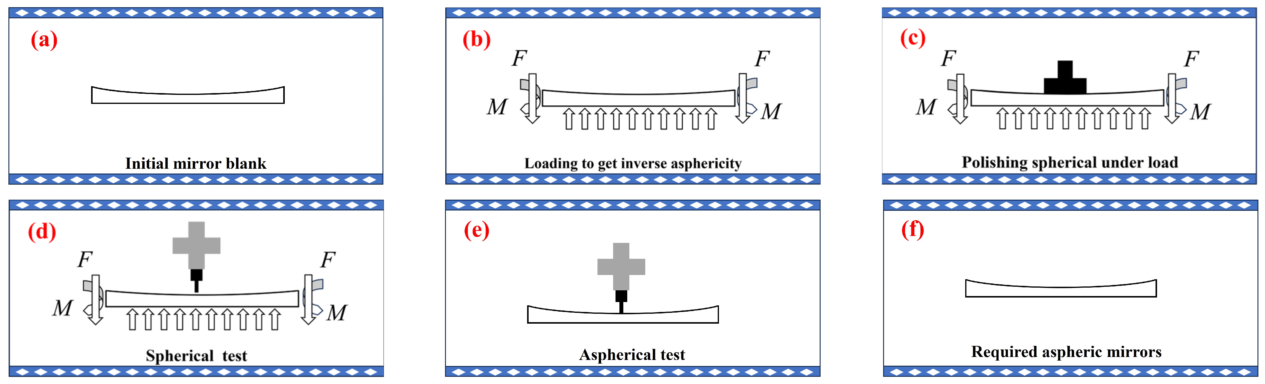
The core principle of SMP technology is to convert aspheric processing into spherical processing. A key aspect of this technology is the precision-controlled shape loading of mirror blanks, which ensures stable control of aspheric and spherical deviation accuracy. The specific process flow of this technology is illustrated in Figure 1 and is detailed as follows.
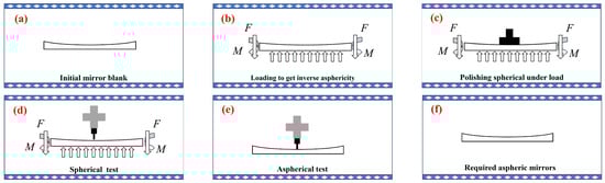
Figure 1.
The basic technical process of SMP. (a) Initial mirror blank, (b) loading to get inverse asphericity, (c) polishing spherical under load, (d) spherical test, (e) aspherical test, (f) required aspheric mirrors.
- The distribution of deviations is calculated between an aspherical surface Sas and its closest spherical surface Ss as: S = Sas − Ss.
- The process begins with the application of given loads applied to the mirror blank, which induces a reverse deviation of −S, as shown in Figure 1b.
- With the loads applied, the mirror blank is polished to its closest spherical surface Ss by a full-aperture polishing pad, with the resulted sphere accurately tested, as shown in Figure 1c,d.
- Once the sphere has met the required accuracy, the applied load is carefully released and the aspherical test is conducted to check whether the required asphere Sas = S + Ss has been obtained or not: if yes, the process ends; if not, step 1 is returned to for a new iteration.
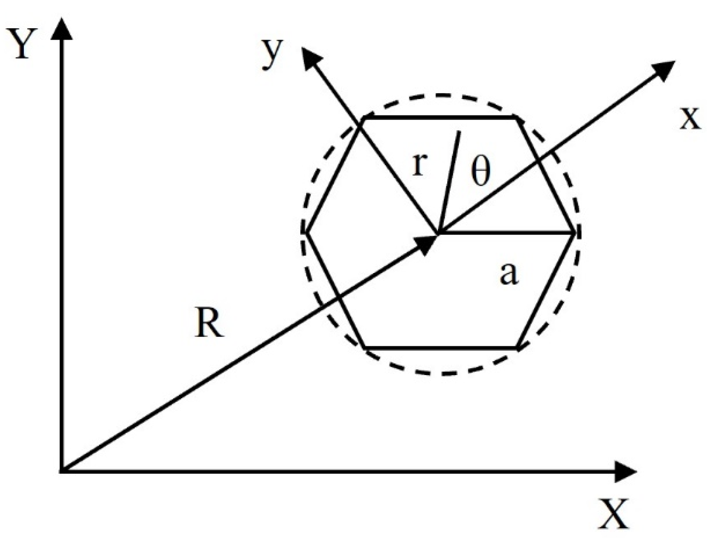
The surface shape of each individual mirror in segmented aperture telescopes, as shown in Figure 2, can be expressed in polar coordinates within its local coordinate system, as shown in Equation (1).
where m and n are even with ; where (x, y) are the local Cartesian coordinates whose center has an off-axis distance of R from the global Cartesian coordinates of (X, Y); where a is the radius of the hexagon inside the circle; and where r and represent the radius and angle, respectively, in polar coordinates.

Figure 2.
Local coordinate system on a single segment.
For most frequently used parabolic surfaces, the coefficients of Equation (1) can be derived to the fifth order to obtain the polynomial coefficients of each order of the surface shape and the corresponding stress coefficients as summarized in Table 1.

Table 1.
Surface shape coefficients and stress coefficients.
According to Nelson’s theory [14,15], one can calculate the continuous load necessary to induce mirror deformation. Detailed expressions for continuous load, continuous shear and uniform pressure for each order of aberration correction are summarized in Table 2.
Table 2.
Continuous bending moment, continuous shear and uniform pressure.
In practical applications, discrete point loading is used to apply these forces. Assuming there are N loading points, each with a distribution angle ), the discrete bending moment and shear force at each loading point are calculated by substituting the results from Table 2 into Equation (2).
The above formulas lay the foundation for subsequent loading surface shape stability studies.
3. Iterative Loading Methods
The fast iterative loading methods in the SMP technique involve examining the surface shape after each iteration of polishing, calculating the new load based on the updated surface shape and starting the next polishing iteration. This cyclic process ensures rapid convergence to the required aspheric surface shape.
A simulation method for iterative loading is proposed to achieve surface shape accuracy after multiple iterations of polishing, significantly reducing fabrication costs and shortening the validation cycle. The schematic flowchart is outlined in Figure 3.
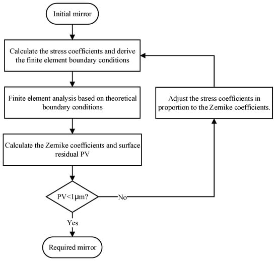
Figure 3.
Schematic flowchart for the simulation of iterative loading of SFOA mirrors.
The basic FEA process is as follows. The base model is an SFOA mirror (F#2.8). Key issues, such as model symmetry, the number of loading points and corrections for reverse loading, must be considered before conducting the FEA. The specific geometrical and material parameters are detailed in Table 3.
Table 3.
Mirror geometry and material parameters.
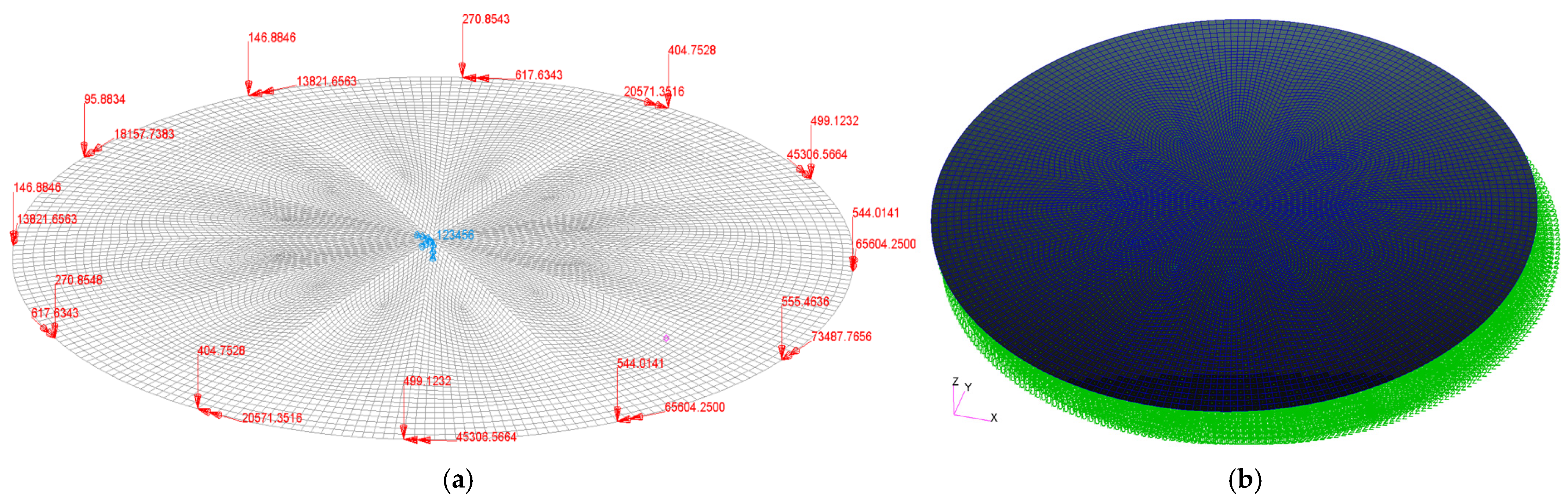
An increase in the number of uniformly distributed loading points enhances the accuracy of surface shape control. The number of loading points should be a common multiple of 2, 3 and 4, such as 12, 24 or 36. According to Yi [16,17], the difference between 12-point and 24-point loading is acceptable. Therefore, choosing 12-point loading would not only save costs but also simplify the loading structure.
Concentrated stresses can lead to sudden changes in surface shape. Theoretically, when the external load is removed, the fixation methods like center or side fixation cause an abrupt variation in surface shape at the original stress concentration. This phenomenon aligns with Nelson’s recommendation of adding a rubber pad between the mirror body and the backing plate. Here, the fixed point is located at the center of the mirror, and a modified uniform pressure is applied to the backside to correct the aforementioned order, as shown in Figure 4. Through numerical simulation, it is found that a centered reaction force of <10−4 N achieves a negligible effect on the surface shape.
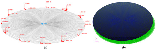
Figure 4.
FE model of SFOA mirror with boundary conditions. (a) Boundary conditions: 12-point loading and center fixation, (b) uniform back pressure.
The iterative loading process is simulated until the residual surface shape error converges to the required accuracy or the relative error between iterations is less than a predefined ratio (e.g., 1%). If the residual surface shape error PV exceeds 1 μm, a scale factor K, defined by Equation (3) with parameters (proportionality between and ) given in Table 4, is introduced to modify the stress coefficients by adding an incremental component of , while is the PV of the residual of the loaded surface.
With K calculated to be ~0.2, the corresponding could be used to optimize the FE boundary conditions. We then complete the FEA based on the newly generated FE boundary conditions. We repeat the judgement of the residual surface shape error PV < 1 μm until the requirement is satisfied and then finish the iteration.
Table 4.
The proportional relationship between the Zernike coefficients and the stress coefficients
.
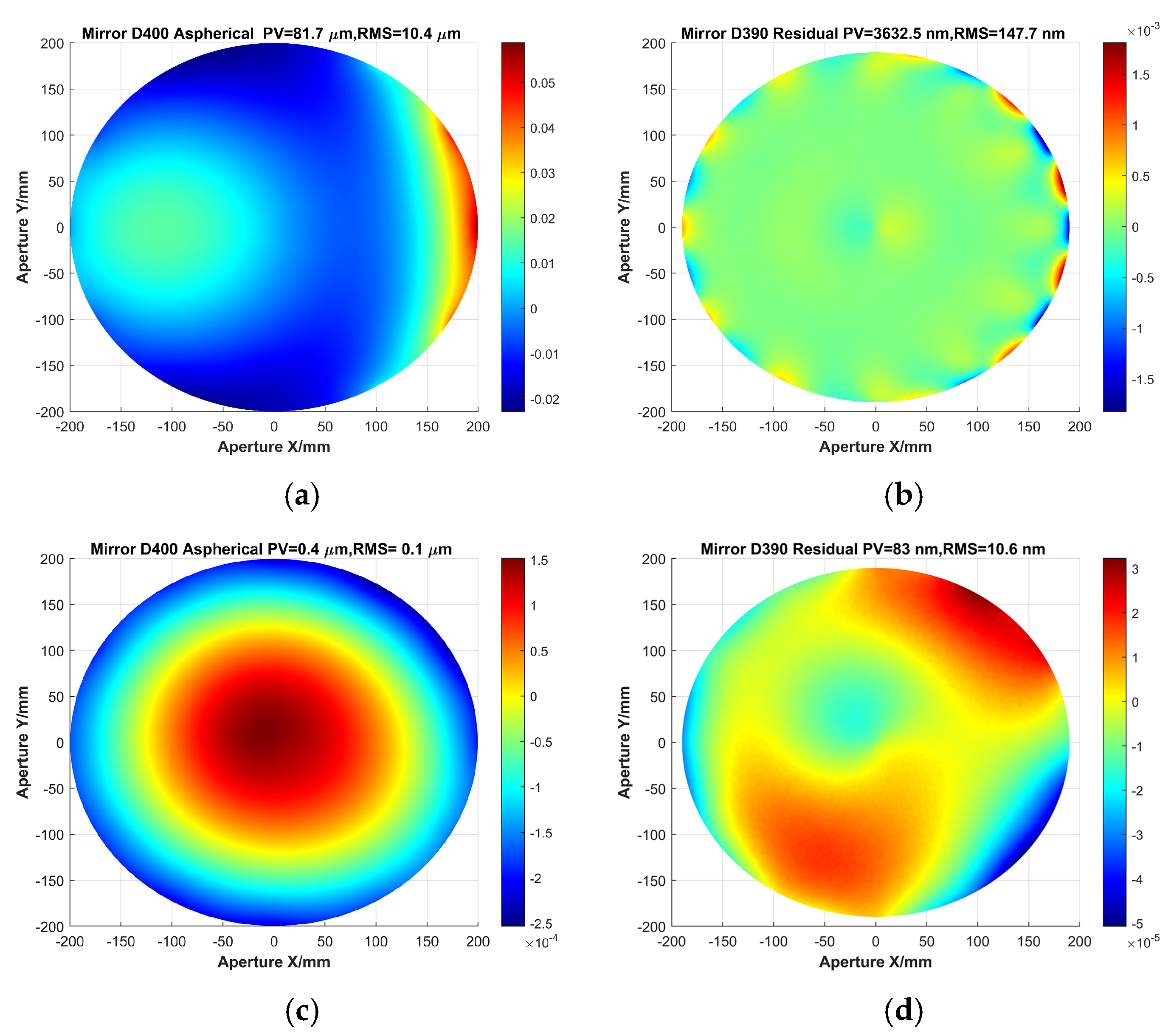
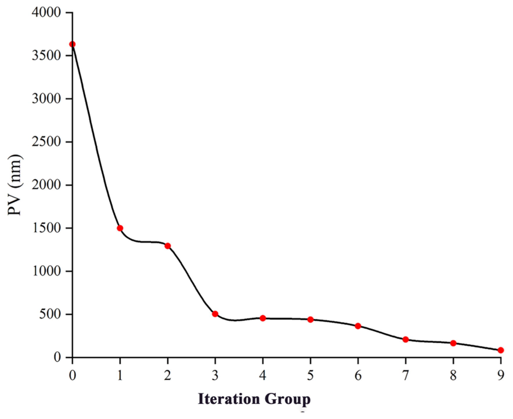
For the SFOA (F#2.8) mirror shown in Table 3, the initial asphericity is 81.7 μm, and the initial residual surface shape error PV is 3.63 μm, resulting in a dynamic range of <23(81.7/3.63≈22.5). After three iterations of removal, the PV drops to <500 nm, representing a significant reduction. From the third iteration onward, convergence is observed as it approaches the limit. By the ninth iteration, the PV has decreased to 83 nm with an RMS of 11 nm. The final residual surface shape error PV is only 2.3% of the initial PV, while the RMS is 7.2% of the initial RMS, indicating substantial reductions. The initial asphericity and residual surface shape error as well as the final results are shown in Figure 5. The change in the residual surface shape error PV for each iteration result is shown in Figure 6. It shows that the loaded PV dynamic range increases from an initial value of <23 to a final value of >980.
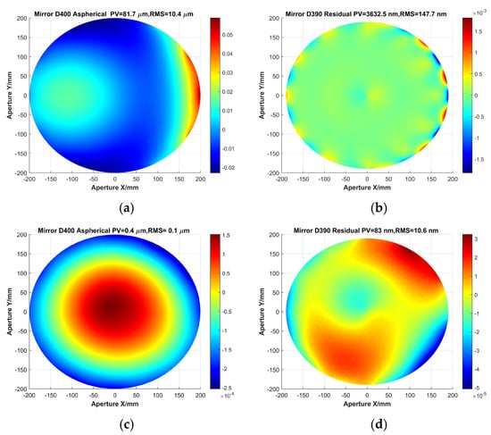
Figure 5.
SFOA aspherical surface shape. (a) Initial asphericity, (b) initial residual surface shape error, (c) ninth iteration asphericity, (d) ninth iteration residual surface shape error.

Figure 6.
Iterative history of the residual surface shape error PV through loading optimization.
The iteration result shows that it encourages people to polish an asphere with 82 μm asphericity to the final precision of 83 nm PV(11 nm RMS, <λ/50 at visible light), just through the SMP technique.
4. Sensitivity Analysis
4.1. Principle of Force and Force Arm Distribution
To balance precision with cost and space, the entire loading scheme is selected as a 12-point side-distributed lever type, as illustrated in Figure 7. To adjust both shear forces and bending moments, each loading point is divided into two loading arms. For a single loading point, the shear force and bending moment required for mirror warping are applied to the loading rod through these two arms, which can be calculated using Equation (4) [18].
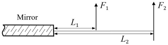
Figure 7.
Schematic diagram of force and force arm distribution.
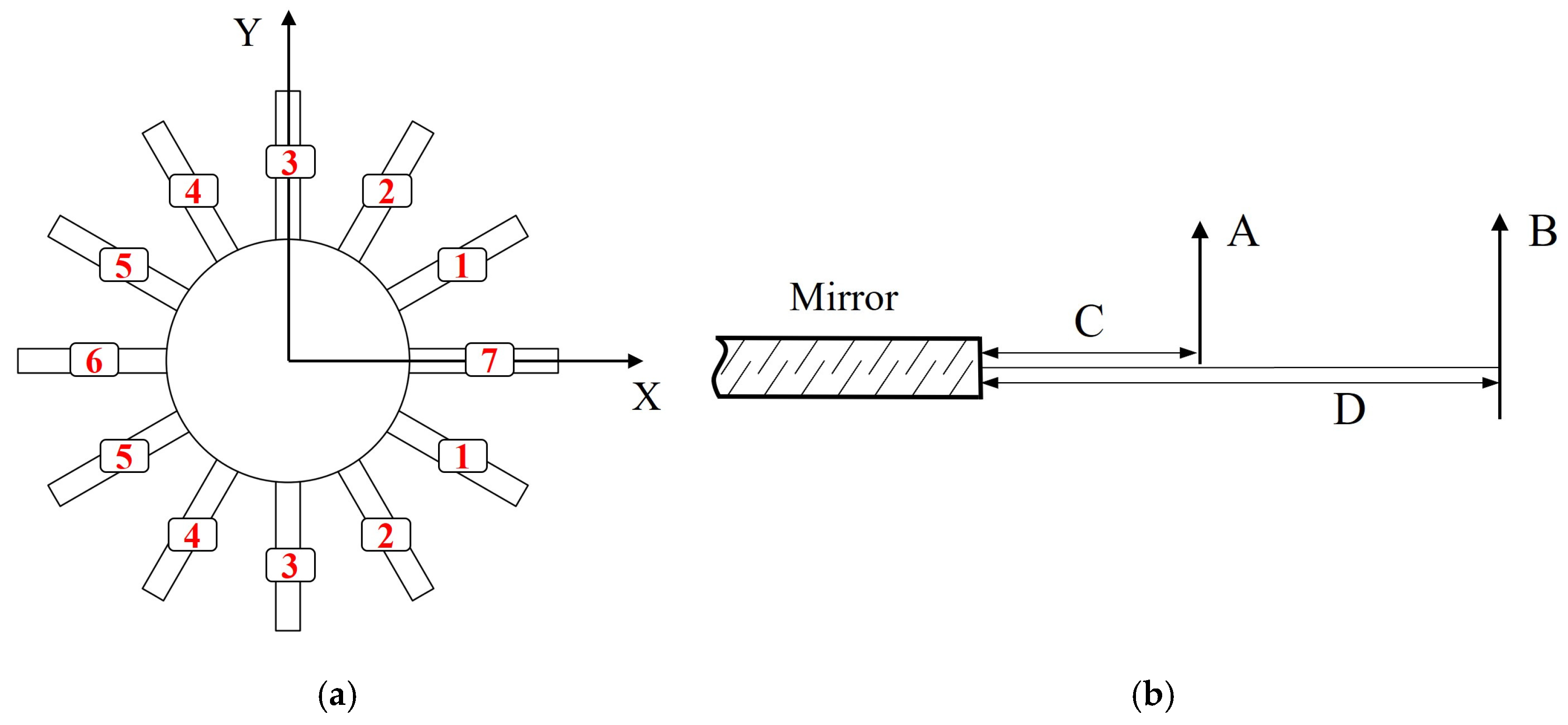
To enable a more effective test analysis, the variables associated with the loading points are regrouped and renamed. Since the 12-point side-distributed lever is symmetric about the X-axis, the points are divided into seven groups numbered in a counterclockwise sequence, as shown in Figure 8a. The variables L1, L2, F1 and F2 of the side-distributed lever are represented by A, B, C and D, respectively, as shown in Figure 8b.
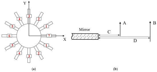
Figure 8.
Variable definition diagram. (a) Loading point groupings, (b) force and force arm.
The influence of the above-described 24 forces and 24 force arms on the surface shape is analyzed by an experimental design method. For symmetry consideration, the design includes 28 variables and one objective function. The variables consist of seven groups of loading points, including the loading arms and forces L1, L2, F1 and F2. The objective function is the residual surface shape error PV.
4.2. Approximate Model Based on Response Surface Methodology
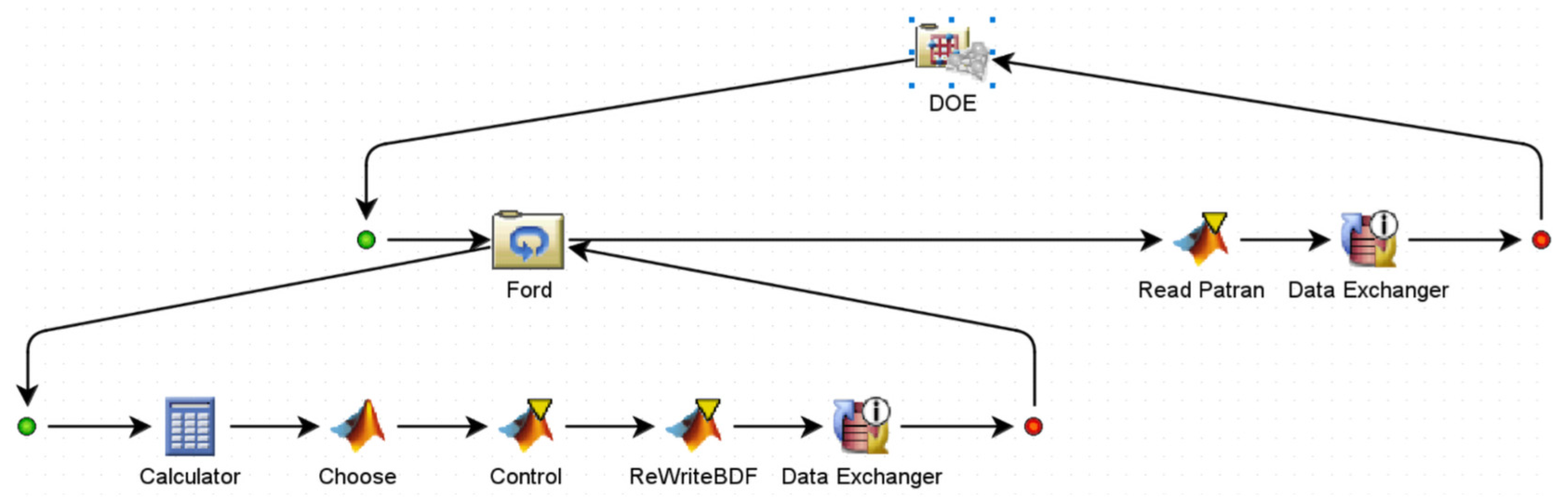
To complete the sensitivity analysis of the surface shape with respect to the design parameters, an integrated workflow which is capable of automatically modifying parameters, performing FEA and conducting post-processing has been established.
The design space is calculated using the Latin Hypercube method from the DOE methodology, which covers all possible combinations of input parameters with limited experiments, thereby reducing testing time and costs. In total, 500 design points are generated using the Latin Hypercube algorithm, which randomly selects the variables within a specified region of the experimental variables. After each selection, all the variables are chosen to form a set of parameters required for the experiment. This selection process is repeated, resulting in 500 sets of experimental parameters. The design point parameters modify the boundary conditions in the FE model. If the boundary reaction force exceeds the tolerance, sub-optimization is performed to reduce it to an acceptable level. Once the requirements are met, post-processing could be conducted to obtain the residual surface shape error PV.
The specific functions of each module in the process are as follows.
The ’Ford’ module is utilized to modify the boundary conditions and run the FE solver to determine the magnitude of the boundary reaction force. At the end of each iteration, it checks whether the branch reaction force meets the specified requirements. If not, the cycle continues.
The ’Read Patran’ module is used to extract the node position and displacement data from the FE results. Post-processing is performed using a custom program to obtain key data, such as asphericity, surface shape residuals and the values of individual aberration terms.
The ’Data Exchange’ module is used to capture key data and save the results from each round of experiments into the DOE for subsequent analysis. The response surface approximation model is shown in Figure 9 [19,20].

Figure 9.
Response surface approximation model optimal solution block diagram.
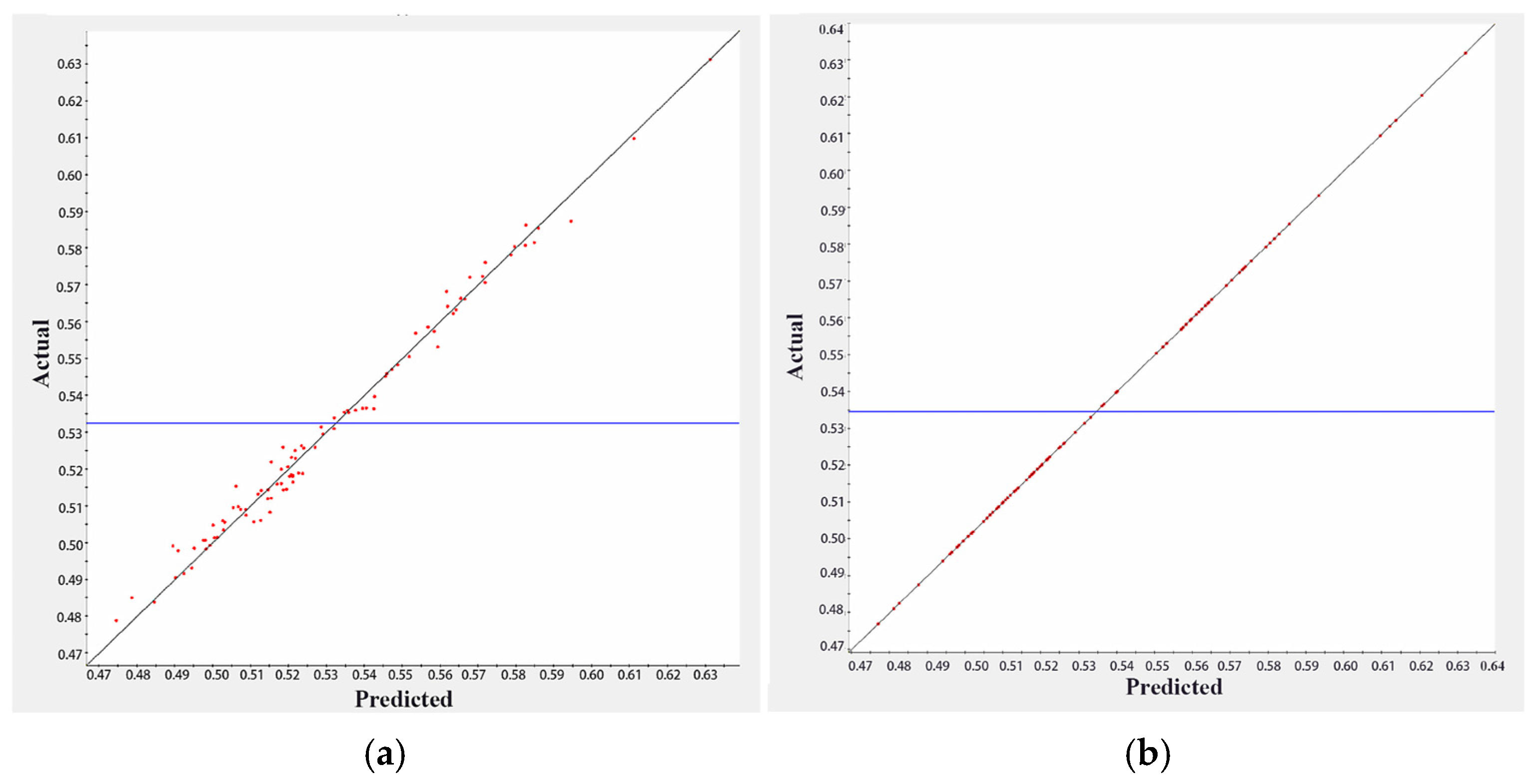
As the approximation model predicts the response value of an unknown point based on the selected basis function, the accuracy of the model should be verified. The complex correlation coefficient indicates the relationship between the actual and predicted values: the closer is to 1, the more accurate the model becomes. The accuracy of both the response surface model (RSM) and the RBF model is verified using K-fold cross-validation. The horizontal coordinates represent the model’s predicted values, while the model’s vertical coordinates represent the actual values, as shown in Figure 10. The blue horizontal line is the mean response value defined by Response Surface Methodology. It is seen that the RSM has .9877 and the RBF model has ≈ 1, so the RBF model is preferred for the subsequent analysis.
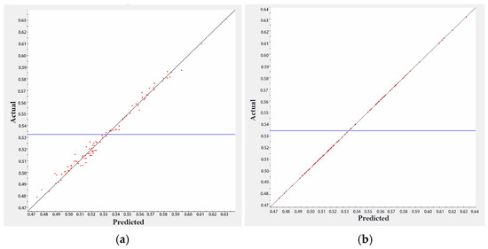
Figure 10.
The complex correlation coefficients index: (a) RSM model, (b) RBF model.
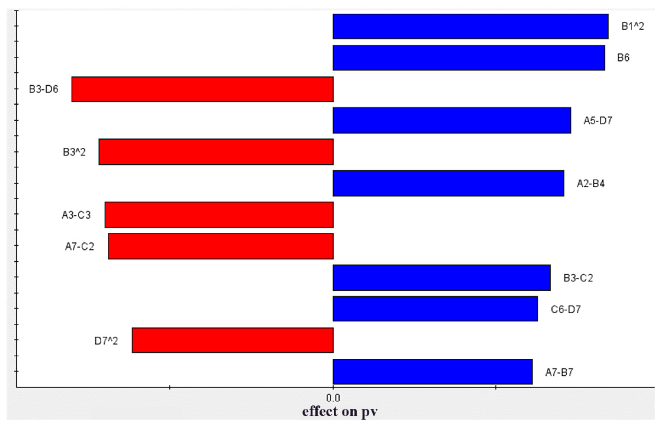
Based on the results of the RBF model, the Pareto contribution of the variables to the residual surface shape error PV can be determined, as shown in Figure 11. Red is used for positive values and blue is used for negative values, which indicates the effect on the results. The results indicate that the single variable with the largest Pareto contribution is item B6, suggesting that the control precision of this variable requires the most attention in the subsequent design.

Figure 11.
Pareto plot of response for the residual surface shape error PV.
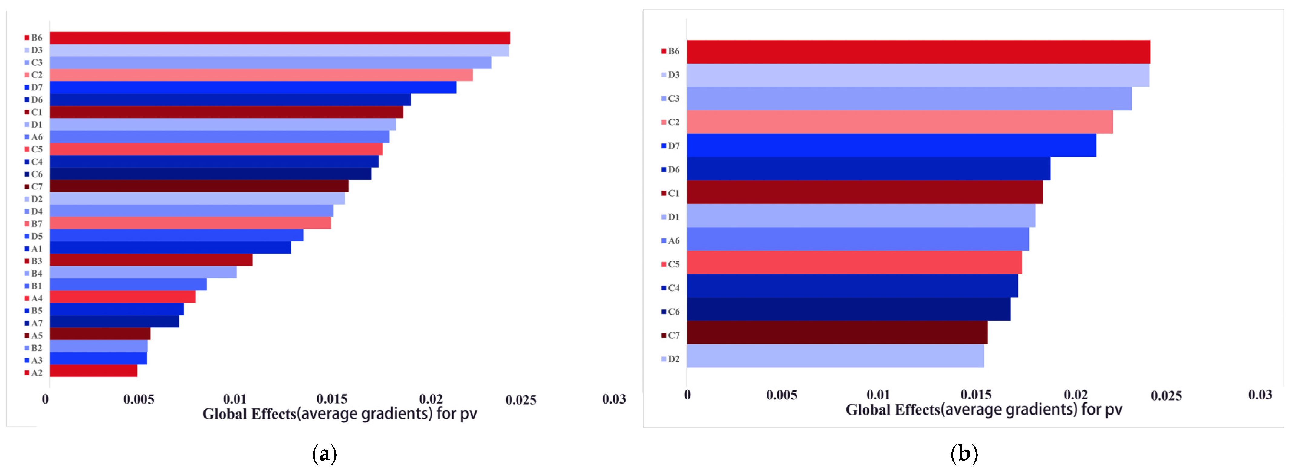
The test range for force arm accuracy is set to [−0.4 mm, 0.4 mm]. While keeping other variables constant, one of the force arms is changed to find extreme values of the residual surface shape error PV through the approximation model. Among the 14 force arm variables, C1 to C7 are with the highest contribution, as shown in Figure 12. The precision of this force arm is analyzed first, with results presented in Table 5. To ensure that the residual surface shape error PV < 600 nm, ±0.1 mm is preferred for force arm C and for force arms 1, 2, 3 and 7 of force arm D. The tolerance of other force arms is ±0.2 mm.

Figure 12.
The degree of global effect for the residual surface shape error PV. (a) All variables; (b) top 14 variables.
Table 5.
Force arms’ tolerance requirement under typical PV.
The accuracy range of the force is determined in the same way. The results indicate that positions A6 and B6 are particularly sensitive, requiring a precision range of ±0.5 N. The tolerance of other force is required to be within ±1 N, as shown in Table 6.
Table 6.
Force tolerance requirement under typical PV.
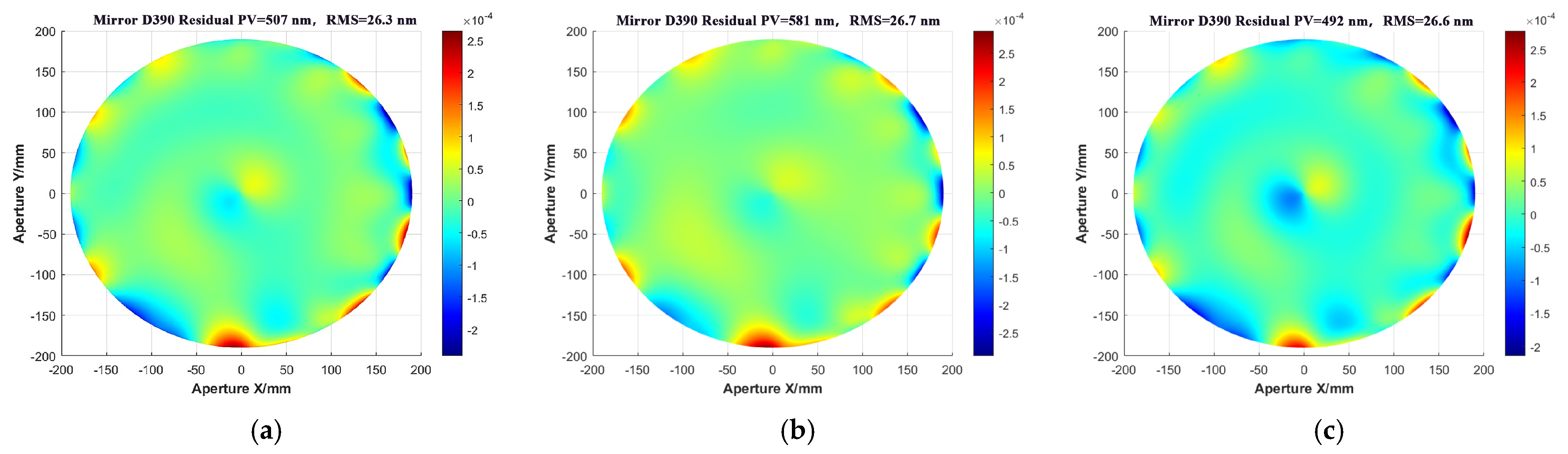
Afterward, the NLPQLP algorithm is utilized (a specialized implementation of sequential quadratic programming) to search for the maximum and minimum of the residual surface shape error PV within the RBF model. This search yields PVmax = 624 nm and PVmin = 483 nm. Due to the error between the approximate model and the actual value, the values of the variables corresponding to the residual surface shape error extremes are substituted into the basic FEA process, yielding the following results: PVmax = 581 nm and PVmin = 492 nm, as shown in Figure 13.
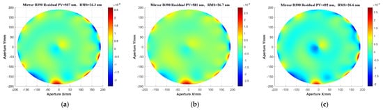
Figure 13.
The extreme values of the residual surface shape error for the RBF model correspond to the FEA. (a) Initial PV, (b) PVmax, (c) PVmin.
The above result is also shown in Table 7, indicating that one could achieve a PV < 0.6 μm, which is much smaller than the targeted 1 μm, allowing ample room for replacing the mirror with one of larger asphericity.
Table 7.
The extreme values of the residual surface shape error PV.
5. Discussion on Larger Asphericity
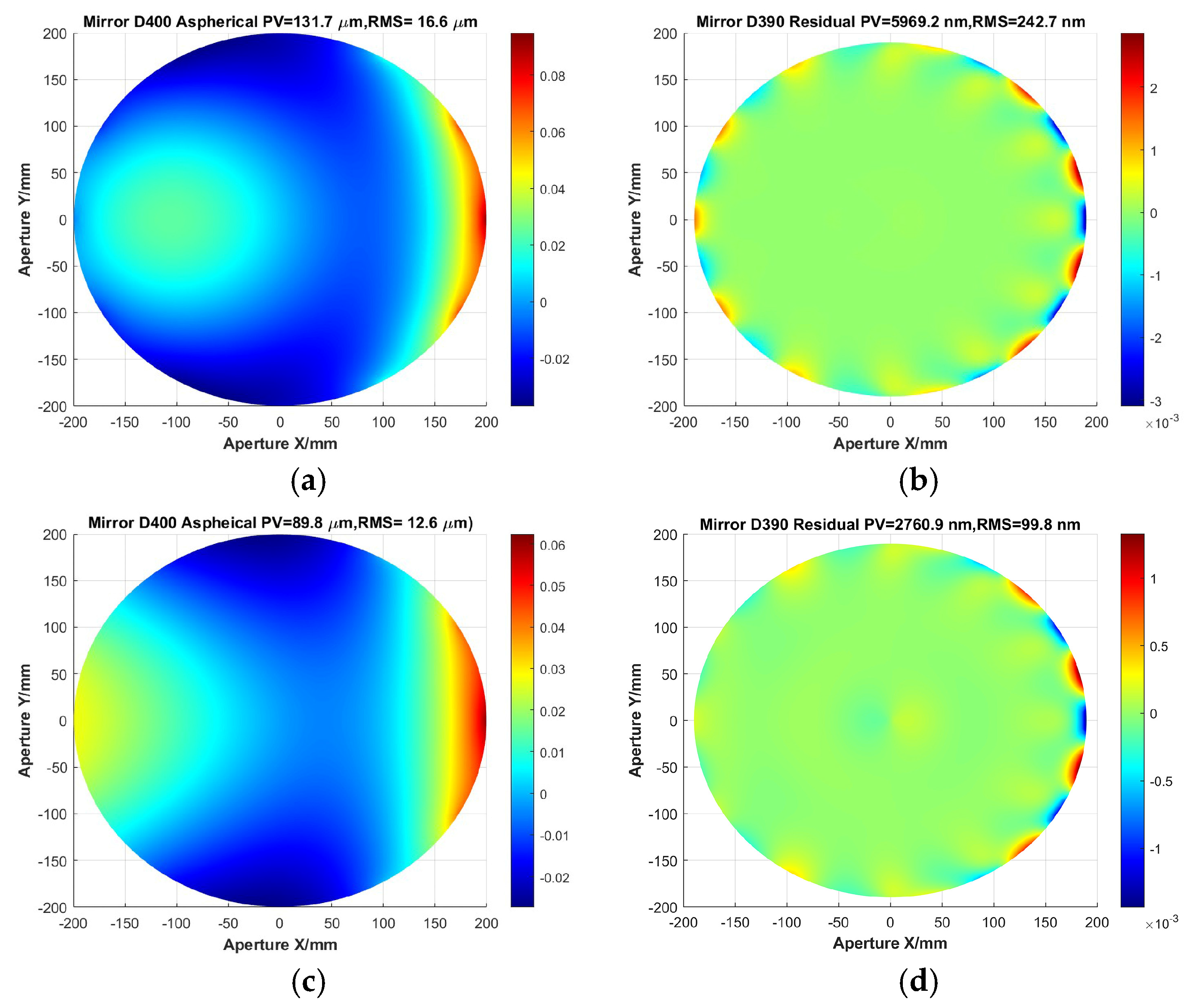
Space applications, particularly for multiple satellites launched within a single rocket, demand more compact and shorter optical systems. Therefore, an aspherical surface (F#2.3) with asphericity greater than 100 μm is employed to assess the applicability of the proposed method.
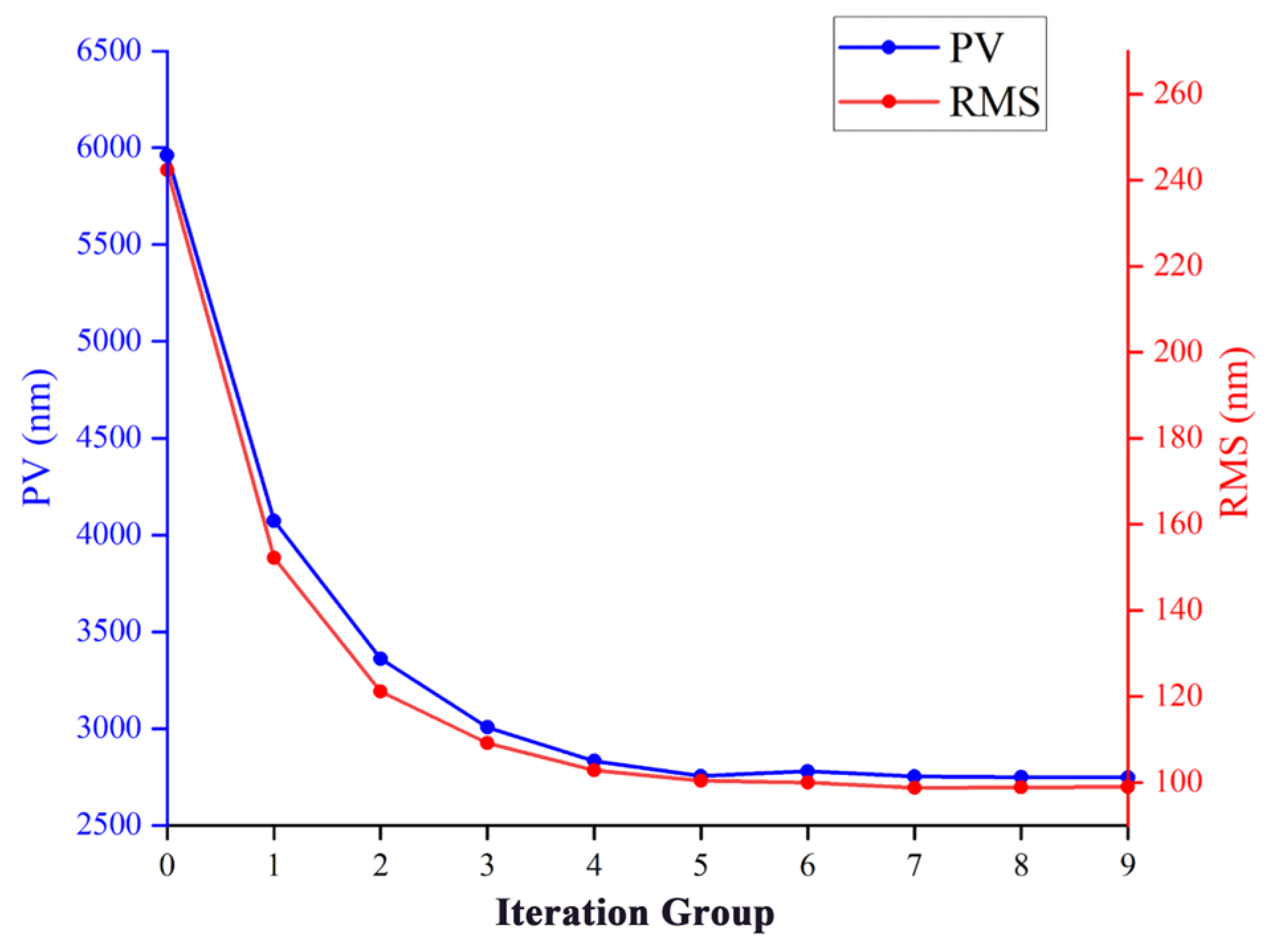
While keeping other inputs unchanged, the asphericity increases sharply as the F# decreases. For the typical case of F#2.3 used for space warning, the asphericity reaches 132 μm. Following the FEA process and the iterative loading methods described previously, the analysis of the mirror surface is completed. The residual surface shape error, starting from an initial value of PV = 5969 nm and RMS = 243 nm, converges to PV = 2761 nm and RMS = 100 nm after nine iterations of iterative loading. The initial asphericity and residual surface shape error as well as the final results are shown in Figure 14. The change in residual surface shape error PV for each iteration result is shown in Figure 15.

Figure 14.
Shorter SFOA aspherical surface shape. (a) Initial asphericity, (b) initial residual surface shape error, (c) ninth iteration asphericity, (d) ninth iteration residual surface shape error.
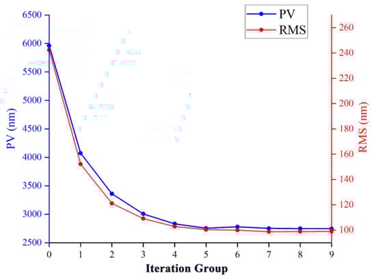
Figure 15.
Iterative history of the residual surface shape error PV and RMS through loading optimization.
Additionally, a program has been developed to simulate the manufacturing process of cutting the edges from a circular shape to a hexagon. This is essential due to the need for mirrors with various final surface shapes, including classic forms such as circles, hexagons, sectors and squares. As shown in Figure 14d, the side-loaded SMP technique causes significant edge effects on circular mirrors, leading to undesired large PV and RMS residual errors. In segmented primary mirrors, the mirror shape is typically hexagonal. Therefore, the circular mirror is trimmed by 7 mm (3 mm for fillet, 4 mm cut for optical aperture on each side), resulting in a hexagonal mirror with an effective aperture of 386 mm. The residual surface shape error after resection of the hexagonal mirrors with one corner located in the X-axes and Y-axes is compared, and the results are shown in Figure 16. It is encouraging that the hexagon with a corner located on the X-axis achieves 983 nm, while the hexagon with a corner located on the Y-axis achieves 960 nm, indicating that both apertures reach the range of PV < 1 μm.
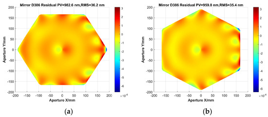
Figure 16.
Surface accuracy of shorter SFOA mirror within two typical hexagonal effective apertures: (a) hexagon aperture located at X-axis; (b) hexagon aperture located at Y-axis.
The results indicate that for aspherical mirrors with asphericity greater than 100 μm, SMP can achieve an accuracy of PV < 1 μm. The results also show that the loaded PV dynamic range is greater than 100 (132/0.98 ≈ 135). It shows that SMP technology is feasible for SFOA mirrors.
6. Conclusions
This paper focuses on studying the Stressed Mirror Polishing (SMP) technique to enhance the surface shape stability of short-focus off-axis aspherical (SFOA) mirrors. The research provides the first comprehensive validation of the rapid iterative loading methods and introduces an integrated optimization approach for deciding the baseline of a loading structure design.
The SMP technology was employed to control the surface shape of SFOA mirrors with an asphericity greater than 100 μm. Validation through a F#2.3 mirror shows that after nine iterations of iterative loading, cutting the circular aperture into a hexagon allows for a surface shape control accuracy of PV < 1 μm, which is sufficient for the subsequent IBF technique. A sensitivity analysis shows that a force precision of 0.5 N and loading arm precision of 0.1 mm could be recommended as the baseline for the lever-type loading structure, achieving a surface shape control error of PV < 0.6 μm. These positive results could encourage the future work of detailed loading structure designs and optical fabrication experimental validation.
Author Contributions
Conceptualization, H.H. and J.L.; software, J.L. and J.Z.; formal analysis, J.L.; investigation, J.L.; writing—original draft preparation, J.L.; writing—review and editing, J.L. and H.H.; visualization, J.L.; supervision, H.P. and L.L.; funding acquisition, H.H. All authors have read and agreed to the published version of the manuscript.
Funding
The work was financially supported by the National Natural Science Foundation of China (Grant No. 62175234), the Scientific and Technological Development Program of Jilin Province (Grant No. 20230508111RC) and the National Key R&D Program of China (2023YFC2206002).
Data Availability Statement
Data are contained within the article.
Conflicts of Interest
The authors declare no conflicts of interest.
References
- Hu, H.X.; Qi, E.H.; Luo, X.; Zhang, X.J.; Xue, D.L. Rapid fabrication strategy for Ø1.5 m off-axis parabolic parts using computer-controlled optical surfacing. Appl. Opt. 2018, 57, F37–F43. [Google Scholar] [CrossRef] [PubMed]
- Lubliner, J.; Nelson, J.E. Stressed mirror polishing 1: A technique for producing non-axisymmetric mirrors. Appl. Opt. 1980, 19, 2332–2340. [Google Scholar] [CrossRef] [PubMed]
- Sporer, S.F. TMT: Stressed mirror polishing fixture study. Proc. SPIE 2006, 6267, 62672R. [Google Scholar]
- Izazaga-Pérez, R.; Aguirre-Aguirre, D.; Percino-Zacarías, M.; Granados-Agustín, F. Off-axis mirror fabrication from spherical surfaces under mechanical stress. Proc. SPIE 2013, 8884, 524–529. [Google Scholar]
- Basheer, A.; Thoutam, K. Design study of Stressed Mirror Polishing (SMP) fixture for segmented mirror telescopes. Int. J. Res. Eng. Technol. 2016. [Google Scholar] [CrossRef]
- Kang, P.; Yang, H.S. New bending system using a segmented vacuum chuck for Stressed Mirror Polishing of thin mirrors. Curr. Opt. Photon. 2017, 1, 618–625. [Google Scholar]
- Li, X.N.; Zhang, H.Y.; Cui, X.Q.; Jiang, Z.B.; Zheng, Y.; Liu, X.T.; Ni, H.K. Study on the stressed mirror polishing with a continuous polishing machine for large aperture off-axis aspheric mirrors. Chin. Astron. Astrophys. 2012, 36, 435–444. [Google Scholar]
- Jiang, Z.B.; Li, X.N.; Yu, B.B.; Zheng, Y.; Li, B. Influence and control of spherical aberration in polishing off-axis aspherical mirrors by the stressed method. Appl. Opt. 2015, 54, 291–298. [Google Scholar]
- Li, X.N.; Jiang, Z.B.; Gong, X.F.; Zhang, H.Y.; Chen, K.X.; Zheng, Y.; Li, B.; Yu, B.B.; Xu, C.; Ji, B.; et al. Stressed mirror annular polishing for scale-down TMT primary segments. Proc. SPIE 2016, 9912, 99120A. [Google Scholar]
- Lemared, S.; Ferrari, M.; Du Jeu, C.; Dufour, T.; Soulier, N.; Hugot, E. Stress mirror polishing for future large lightweight mirrors: Design using shape optimization. Opt. Express 2020, 28, 14055–14071. [Google Scholar] [CrossRef] [PubMed]
- Roulet, M.; Hugot, E.; Atkins, C.; Marcos, M.; Lombardo, S.; Bonnefoi, A.; Caillat, A.; Ferrari, M. Off-axis parabolas super polished under stress: The case of the Roman Space Telescope coronagraphic instrument mirrors. Opt. Express 2020, 28, 30555–30569. [Google Scholar] [CrossRef]
- Jiang, Z.B.; Li, X.N.; Chen, Z.; Cao, T. Application progress of stressed mirror continuous polishing technology in the segments fabrication of telescope primary mirror. Proc. SPIE 2020, 11451, 114510H. [Google Scholar]
- Luo, X.; Qi, E.H.; Hu, H.X.; Hu, H.F.; Ford, V.G.; Cole, G. Fabrication and metrology study for M3MP of TMT. Proc. SPIE 2016, 9682, 968209. [Google Scholar]
- Nelson, J.E.; Gabor, G.; Hunt, L.K.; Hunt, L.K.; Lubliner, J.; Mast, T.S. Stressed mirror polishing 2: Fabrication of an off-axis section of a paraboloid. Appl. Opt. 1980, 19, 2341–2352. [Google Scholar] [CrossRef]
- Nelson, J.E.; Mark, T.R. The Off-Axis Expansion of Conic Surfaces; Report No. 91; UC TMT (Keck): Waimea, HI, USA, 1982. [Google Scholar]
- Yi, L.Q.; Zhang, X.J.; Hu, H.F.; Zhang, Z.Y.; Zeng, X.F. Research on Stressed Mirror Polishing of Off-Axis Aspheric Silicon Carbide Thin Plate Mirror and Lightweight Mirror; Changchun Institute of Optics, Fine Mechanics and Physics, Chinese Academy of Sciences: Changchun, China, 2021. [Google Scholar]
- Yi, L.Q.; Zhang, X.J.; Hu, H.F.; Zhang, Z.Y.; Hai, K.; Luo, X.; Xue, D.L. Comprehensive study of the rapid stressed mirror polishing method for off-axis aspheric SiC thin-plate mirrors. Opt. Express 2020, 28, 32802–32818. [Google Scholar] [CrossRef] [PubMed]
- Wang, H.R.; Zhang, M.Z.; Zuo, Y.X.; Zheng, X.Z. Research on elastic modes of circular deformable mirror for adaptive optics and active optics corrections. Opt. Express 2019, 27, 404–415. [Google Scholar] [CrossRef] [PubMed]
- Hu, R.; Liu, S.T.; Li, Q.H. Topology-optimization-based design method of flexures for mounting the primary mirror of a large-aperture space telescope. Appl. Opt. 2017, 56, 4551–4560. [Google Scholar] [CrossRef]
- Guo, J.; Zhu, L.; Zhao, J.; Gong, D.P. Design and optimization of high tolerance support structure for large aperture space mirror. Opt. Precis. Eng. 2019, 27, 1138–1147. [Google Scholar]


Disclaimer/Publisher’s Note: The statements, opinions and data contained in all publications are solely those of the individual author(s) and contributor(s) and not of MDPI and/or the editor(s). MDPI and/or the editor(s) disclaim responsibility for any injury to people or property resulting from any ideas, methods, instructions or products referred to in the content. |
© 2025 by the authors. Licensee MDPI, Basel, Switzerland. This article is an open access article distributed under the terms and conditions of the Creative Commons Attribution (CC BY) license (https://creativecommons.org/licenses/by/4.0/).