Abstract
Eccentricity faults are one of the main causes that significantly affect the performance of permanent magnet synchronous machines (PMSMs). Monitoring eccentricity in real time could prevent failures by adapting operation conditions and maintenance schedule when early signs of deterioration are detected. This article proposes making a circuit-type model of a permanent magnet machine with an easily configurable eccentricity for simulations and real-time analysis of signals under different operating conditions. The basis for the construction of the circuit model will be the simulation of the PMSM with 49 different coordinates of the rotor center, using the finite element analysis (FEA). The presence of eccentricity causes a variation in the inductances, the no-load flux and the expansion torque depending on the position of the rotor. The model proposes the use of bilinear interpolation (BI) to estimate the inductance matrix, the no-load flux vector captured by the stator winding and the cogging torque due to the presence of the magnets in the rotor, all of them for each rotor position. The validation is done by comparing the precision in the results of the machine’s self-inductances, the torque and the voltage waveform at the PMSM terminals and the static torque of the PMSM. The circuit model results are validated in two ways: (1) through experimental simulation, comparing the same results obtained using FEA and (2) through practical experimentation, producing a dynamic eccentricity in the machine of 0.3 mm. The results show that the proposed model is capable of accurately reproducing the behavior of the PMSM against eccentricity faults and presents computational time savings close to 99% compared to the response time obtained using FEA. This rapid PMSM model, parameterizable according to the degree of eccentricity, is the basis for the real-time simulation of the main machine waveforms, such as voltage, current and torque.
1. Introduction
Electrical machines are very important components in production processes. Depending on the application, different types of machines can be considered. For example, in traction applications, permanent magnet synchronous machines (PMSMs) are widely used due to their high efficiency and power density. Due to their essential role, the appearance of faults in PMSMs leads to an unacceptable loss of production. Many of these faults are progressive, that is, the degradation gradually increases and affects the performance of the machine. These faults can cause several consequences on electrical machines, such as distortion of the magnetic field, overheating phenomena, risks of electric arcs, vibration effects, high and unbalanced currents, electromechanical torque oscillation and noise. If they are not detected in time, these faults can become catastrophic by causing the machine to stop.
Generally speaking, and in accordance with the nature of the fault, three types of common faults can be found in PMSMs [1]: electrical faults, demagnetization of magnets and mechanical faults. Electrical faults on the stator account for 38% of all machine faults [2]. These involve incorrect connection of machine windings, grounding errors, short circuit of stator phase windings and open circuit of one phase [1]. Demagnetization of magnets can be caused by high temperatures, high stator currents or aging of the magnets [3]. Demagnetization causes oscillations in the machine’s torque and increases the temperature if the same torque level is maintained. This leads to abnormal operations of the PMSM and reduces its efficiency [1]. Mechanical faults include excessive vibration, shaft bending, loose fasteners, bearing defects, rotor eccentricity and permanent magnet breakage [1]. Bearing defects alone represent more than 40% of electrical machine defects [2]. They can be caused by many factors, the most common of which are fatigue, wear, the flow of zero-sequence currents through bearings, plastic deformation and corrosion. Defects in the bearings lead to torque oscillations, rotor eccentricity [4] and variations in the air gap thickness between the rotor and stator. It can be static eccentricity, dynamic eccentricity or mixed eccentricity [5]. Eccentricity is also considered as one of the mechanical sources of electromagnetic vibrations [6]. An eccentricity fault with 10% severity is probably the only existing fault in a brand new healthy electrical machine that is acceptable as a manufacturing tolerance [7].
Normally, eccentricity modeling in PMSMs is carried out using computational software that presents great precision in its results, such as finite element analysis (FEA) [8,9]. It is based on magnetic field calculations and considers the geometry and material of the machine.
FEA modeling is very accurate and flexible, but due to its complexity, for dynamic modeling of a PMSM, the algorithm needs to solve for a lot of elements/variables and requires a lot of computational time. FEA-based software can calculate magnetic field distribution in any electrical machine. From here, it is possible to easily obtain all the parameters and characteristics of the machine, such as magnetic flux density, inductances, electromagnetic torque and even voltages and currents in the windings [10].
The review of the literature details that it is possible to simulate a PMSM and consider the presence of an eccentricity fault, but no models are found that are easily configurable and that allow different types of physical quantities to be observed simultaneously. An important point of using fast and easily parameterizable models based on eccentricity is the generation of databases that are conducive to training intelligent eccentricity diagnosis models. The results of [11] indicate that AI-based methods outperform traditional methods for fault diagnosis in PMSMs, demonstrating their effectiveness in an industrial condition monitoring application. The integration of AI in eccentricity diagnosis represents a step towards improving the reliability and performance of PMSMs, highlighting the importance of leveraging cutting-edge technology in the diagnosis of these machines.
In [12], FEA is used to model a PMSM with static, dynamic and mixed eccentricity; however, the model is not easily parameterizable, that is, each type and severity of eccentricity must be reproduced using FEA, which would require high computational calculation times. It is important to reduce these models to speed up calculation time. However, it is also necessary to maintain good precision in the results so as to not compromise the analyses and make their integration into real-time calculation platforms possible, as has already been shown in other studies [13,14,15]. Because the dynamic eccentricity (DE) and mixed eccentricity (ME) have a time-varying air gap length, its analysis requires a full time step FEA, which is slow compared to the static finite element method that can be used for static eccentricity (SE). Furthermore, the finite element method cannot provide analytical mathematical relationships between the variables in question and the degree of eccentricity, especially in the case of the ME. Therefore, the finite element method has often been used to verify the other methods [11].
In the same order of ideas, Ref. [16] proposed a real-time model that allows detecting dynamic eccentricity in PMSM. Their methodology is based on monitoring the motor speed and the back-electromotive force induced in an additional winding. After deriving a mathematical equation of the back-electromotive force (EMF) induced in a toothed winding, they proposed a fault detection signal, which is the EMF in the additional winding divided by the rotation speed. The validation of their method was performed using 2D FEA and experimental validation with dynamic eccentricities of 0, 25% and 50%. However, although the method proved to be effective for the detection and diagnosis of dynamic eccentricity in PMSM, it presents a major disadvantage, namely the requirement of an additional winding. In addition, there are no results associated with the presence of other types of eccentricity such as static or mixed. To help analyze the electromagnetic characteristics of PMSMs due to rotor eccentricity, such as electromagnetic torque and back electromotive force, ref. [17] propose an analytical model to analyze the influence of rotor eccentricity on the electromagnetic characteristics of a PMSM, specifically the effect on magnetic flux, induced back EMF and torque. Their method was validated using FEA and experimental tests.
Beyond electrical measurements, mechanical aspects associated with eccentricity have also been considered. In [18] is presented a model and experimental verification of a four-degree-of-freedom rotor considering combined eccentricity and electromagnetic effects, demonstrating the complexity of the interactions involved. The dynamic response is verified by experiments where the results agree well in terms of the rotor trajectory shape compared to the dynamic model results.
This work builds on these previous efforts by developing a new real-time model for a PMSM that incorporates static, dynamic and mixed eccentricity effects, based on knowledge of their geometry and the materials that compose them. The proposed model will have the three types of eccentricity and will be easily configurable to modify their degree of severity, and it will be validated through FEA and practical experimentation.
2. Eccentricity Fault in PMSM
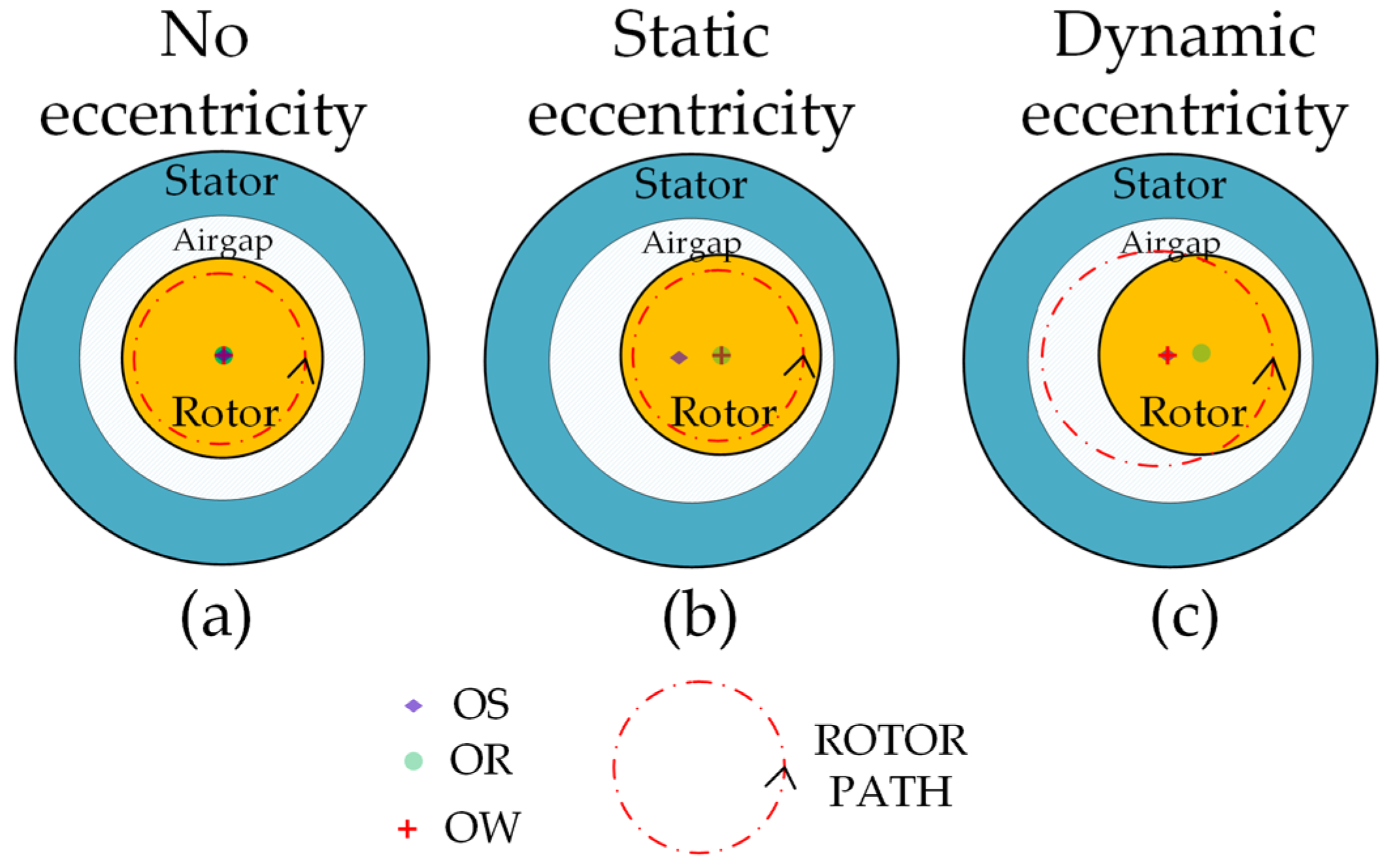
Eccentricity represents a condition of a non-uniform cylindrical air gap between the stator and the rotor. As shown in Figure 1a, when the rotor symmetry center (OR), stator symmetry center (OS) and rotor rotation center (OW) coincide, indicating that the air gap is uniformly distributed, the machine may be considered without the presence of eccentricity. Eccentricity occurs when one of these axes is separated from the other two, or when all three axes are separated. Specifically, OS separating from OR and OW is called SE; dynamic eccentricity DE occurs when OR separates from the other two centers, and ME is the separation of the three centers [19].
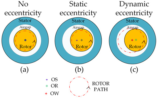
Figure 1.
Graphic representation of eccentricity on the machine. (a) Healthy machine; (b) Static eccentricity; (c) Dynamic eccentricity.
At static eccentricity (Figure 1b), the rotor rotates around its own geometric axis. In dynamic eccentricity, the rotor rotates with the same geometric axis of the stator (Figure 1c). The third category is mixed eccentricity, which refers to the coexistence of static and dynamic eccentricity in the machine. Dynamic eccentricity is mainly caused by rotor mass imbalance. Radial centrifugal force occurs when the machine rotates, resulting in an uneven air gap between the stator and rotor [6]. Bearing (outer ring) wear leads to static eccentricity. The presence of a defect in a ball causes a dynamic eccentricity.
3. Modeling-Based Approaches
Fault modelling is one of the most significant and vital steps for the fault diagnosis in machines [20,21]. The idea of modeling is to measure the deviation between the output of an analytical model and the actual output of the machine, then predict a potential failure signature which allows a diagnosis of the fault. According to the literature, modeling-based approaches for PMSMs include equivalent electric circuit (EEC), magnetic equivalent circuit (MEC) and numerical methods (NMs) [22]. Those based on EEC use a mathematical approach to calculate the electrical quantities of the machine based on geometry. Machine parameters such as inductance can be calculated using machine geometry and winding configuration. EEC-based models can be subclassified into coupled circuit (CC) modeling, winding function theory (TFE)-based modeling, and modified winding function theory (TMFE)-based modeling [22]. Furthermore, methods are reported in the literature that allow the diagnosis of eccentricity in PMSMs based on the analysis of the frequency components that are present in the machine current spectrum, which can be included in models based on EEC.
The method based on the CC model requires very good precision to reproduce all the magnetic couplings between the circuits, and the performance of the model directly depends on the precision of its parameters. Also, the best approach is to calculate the model parameters with another model based on finite elements. As with CC, TFE requires machine geometry and design data to calculate inductances, but it uses an analytical approach. The calculation time required is less than CC but the precision is low. TMFE uses the same approach as TFE but considers spatial effects, such as air gap non-uniformity and harmonics, when calculating inductances. MEC-based approaches model the magnetic circuit using sources of magnetomotive forces (MMFs) and reluctances; the output variables are electrical quantities as for CEE. For the study of this modeling approach, the geometry of the machine, the magnetic parameters of the material and the winding distribution are considered [22].
Finally, NMs are based on solving Maxwell’s equations using the FEA. They require more computing resources and large calculation times. However, these methods provide more accurate results [22,23,24].
Seeking to reduce the computational cost to diagnose faults, hybrid techniques are also found in the literature that combine two conventional approaches, such as the hybrid analytical–numerical method (EEC-NM) presented in [25] and Ref. [26] for the study of winding and demagnetization faults.
4. PMSM Modeling in FEA
FEA is considered the most precise in terms of results obtained and requires a lot of computational time. Maxwell’s equations, which describe the behavior of electric and magnetic fields in space, are the foundation for PMSM simulation using FEA. They represent a set of four coupled partial differential equations that govern electric and magnetic fields as a function of time and position in space.
To incorporate Maxwell’s equations in the FEA, specific formulations are used for the simulation of electromagnetic problems. Domain discretization is performed by considering finite elements in which unknown variables, such as magnetic and electric fields, are approximated by shape functions. These shape functions allow variation in these variables across the domain to be efficiently represented. The modeling includes all the geometric complexities of all the parts of the machine, including the stator, the rotor and the magnets mounted on it. In addition, the spatial distribution of the stator windings, the non-uniform air gap for modeling eccentricity, the physical conditions of the stator conductors and the rotor are considered. The input is a three-phase sinusoidal current represented as three currents injected into the machine windings, one for each phase. The transient equations of the external circuit and the circuit elements are combined with the magnetic field equations.
In 2D simulation, the electromagnetic equation analyzed by FEA is represented as in [8]:
It should be noted that there is only one non-zero component for the vectors and along the z axis for a 2D simulation that we denote and . is the vector potential, and is the magnetic permeability. is the current density related to the applied voltage, is the current density related to the time variations of the magnetic flux and is the current density related to the motional voltage.
If we consider that , and (ν is equal to zero with the application of a fixed reference frame), then (1) is rewritten as:
where is the electrical conductivity, is the machine length along the z-axis, is the applied voltage per phase and is the speed of the conductor against magnetic flux density.
The electric circuit equation is given by the following:
where is the resistance in each phase of the winding, is the current that circulates through the winding, is the number of turns and is the flux links captured by the coil.
Starting from an initial condition (generally and are set to zero), Equations (2) and (3) are solved by FEA through a modeling of steps in time (or steps in the rotor position) to obtain the potential vector and the stator current . Once the vector potential is obtained, the magnetic flux distribution can be obtained as follows:
FEA can calculate the magnetic field distribution in any electrical machine. From here it is possible to obtain all the parameters and characteristics of the machine, such as magnetic flux density, inductances, electromagnetic torque and even the voltages and currents in the windings.
5. PMSM Modeling in Coupled Circuits
An electrical machine can be represented by the classical voltage equations of the stator and rotor as well as the electromagnetic torque equation in the frame abc. These equations are represented in terms of resistance, self-inductance and mutual inductances. The design of this model is mainly based on the basic geometry and winding arrangement of the arbitrary phase machine. In such a model, the parameters are considered to vary over time and depend on the position of the rotor.
For a PMSM the coupled circuit model can be written as
where:
| Voltage vector , in V. | |
| Current vector , in A. | |
| Resistance matrix , in Ohms | |
| Inductance matrix , in H. | |
| Vector of the fluxes produced by the permanent magnets and captured by the phase windings of the stator , in Wb. | |
| Rotor angular position, in degrees. | |
| Number of circuits. |
If we introduce the mechanical speed of rotation of the rotor in rad/s, Equation (5) can be expressed as (6)
If in Equation (6) we solve for the current derivative, we find (7):
To solve Equation (7), it is necessary to identify the PMSM model, that is, knowing , , . If we consider that the voltage is imposed, the one unknown is the stator current vector .
The expression for the electromagnetic torque may be written in machine variables as the partial derivative of the coenergy with respect to the angular position of the rotor [27]:
in which
is the energy in the coupling field due to the presence of the permanent magnets and is the pole pairs number.
5.1. Coupled Circuit Model Parameterizable as a Function of Eccentricity
Equation (7) represents the solution that describes the behavior of the PMSM under its different operating conditions. The coupled circuit model is completed in the Simulink/MATLAB R2022a environment to generate programmable faults capable of quickly reproducing the effects of an eccentricity fault on the electrical and mechanical quantities of the machine. To do this, it is necessary to identify inductance matrices linked to each of the faults to be simulated. To simulate the eccentricity, inductance matrices will be identified numerically according to the position , of the center of the rotor and its angular position . This identification procedure will be repeated as many times as necessary by imposing new values of , and . Matrix processing will then be carried out in Matlab to produce fully configurable faults of eccentricity by making, for example, interpolations between results for sets of discrete values of , and . This will make it possible to reconstruct an inductance matrix suitable for the eccentricity fault situation under study.
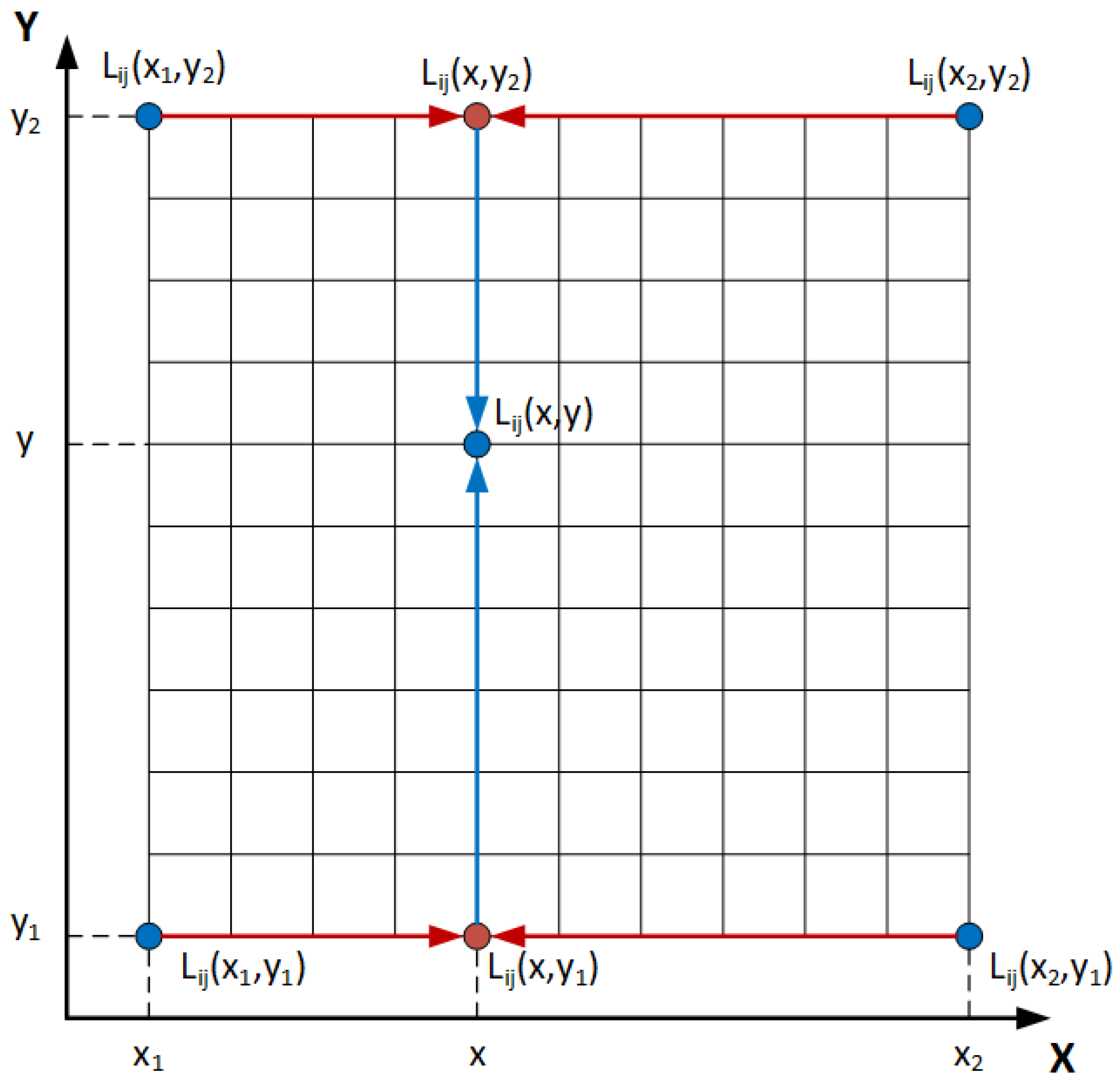
In the presence of eccentricity defined by rotor center coordinates (, ), we propose to carry out a bilinear interpolation (BI) to estimate all the parameters of and for each rotor position. The mathematical interpolation is made knowing the parameters in the coordinates, , , and . The expression which corresponds to any eccentricity for and can be derived from Figure 2.
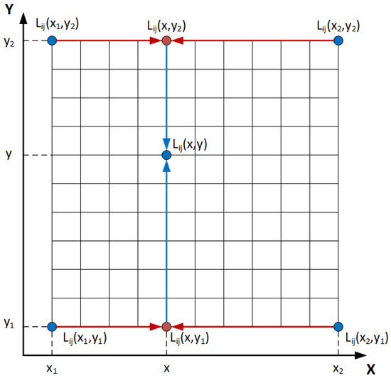
Figure 2.
Graphical representation of bilinear interpolation.
For each position of the rotor, we can start for an interpolation in the axis
Next, we do an interpolation in the Y axis
By replacing (10) and (11) in (12), we obtain
For the case of DE, where the and coordinates change with the rotor position , the and coordinates are given as
where is the degree of dynamic eccentricity. In the case of ME, the component of SE (, ) are added to the components of DE to obtain the and components
The same approach is applied for the estimation of the no-load flux captured by the stator windings and for the cogging torque due to the presence of the permanent magnets in the rotor.
5.2. Model Identification
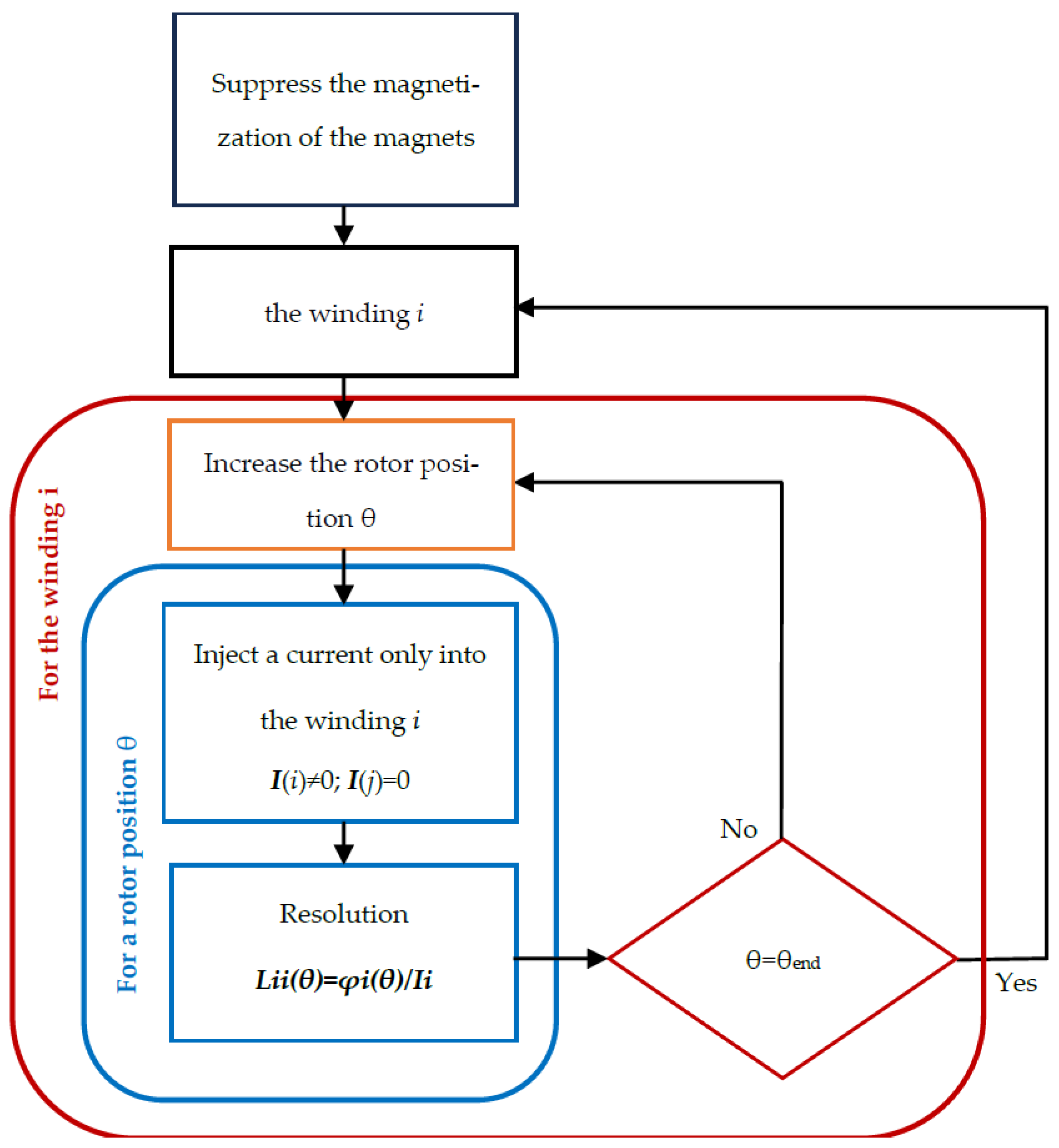
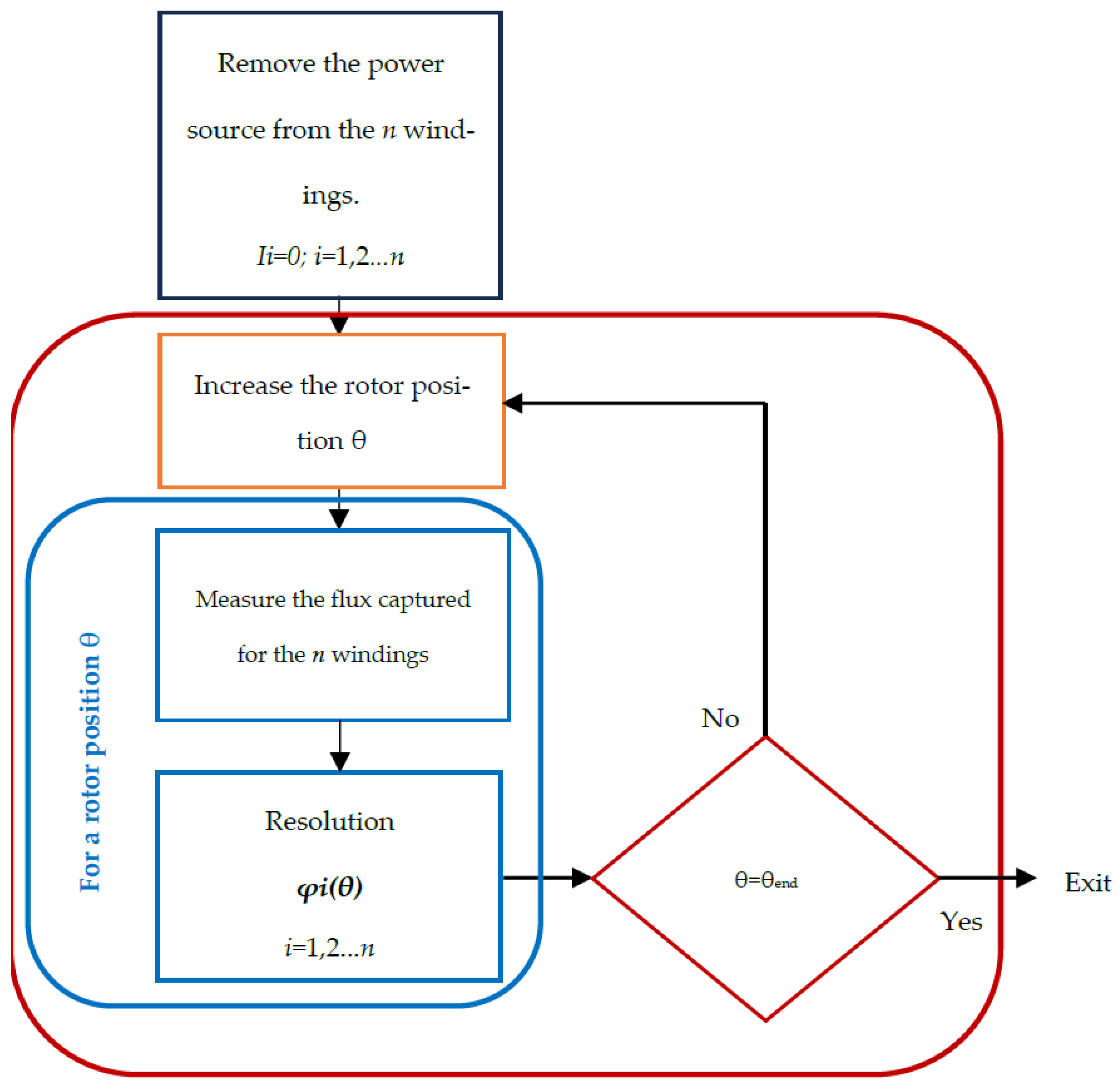
To calculate the currents, torque and other machine variables, it is necessary to have previously identified the resistance matrices , inductance matrices and the no-load flux vector using the Flux2D field calculation software, as a function of the angular position of the rotor . Based on the knowledge of the geometry and construction material of the machine, field calculation software (linear and magnetostatic) will be used to identify the model parameters (collected in high-order matrices). Figure 3 and Figure 4 show the procedure to follow to obtain and using the Field calculation software.
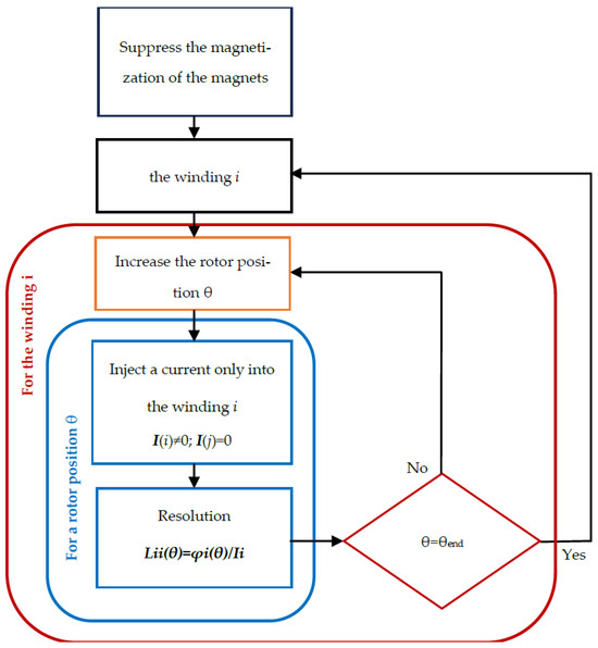
Figure 3.
Procedure for the identification of of given machine excentricity , with FE model.
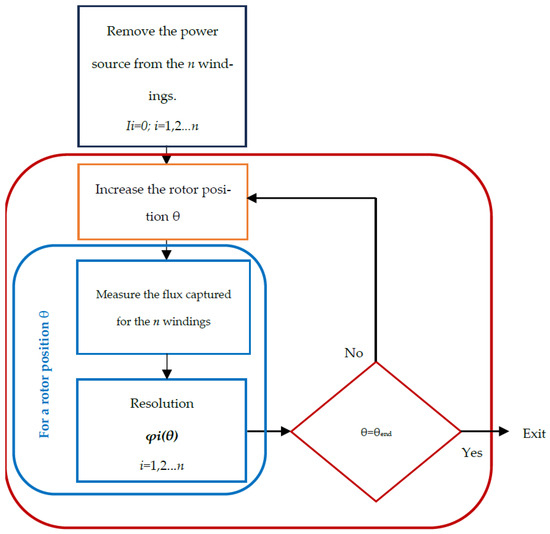
Figure 4.
Procedure for the identification of of given machine excentricity , with FE model.
To follow the procedure for identifying of a PMSM with an FEA model shown in Figure 3, with the magnetization of the magnets suppressed, a simulation in steps of 0.5 degrees will allow identifying , for the and eccentricity coordinates. By supplying the winding with a direct current of 1 A, it can be deduced that the measured inductances will be equal to the flux captured for the coils. A similar procedure is carried out in Figure 4 to determine the no-load flux captured by the stator coils when the current flowing through them is zero.
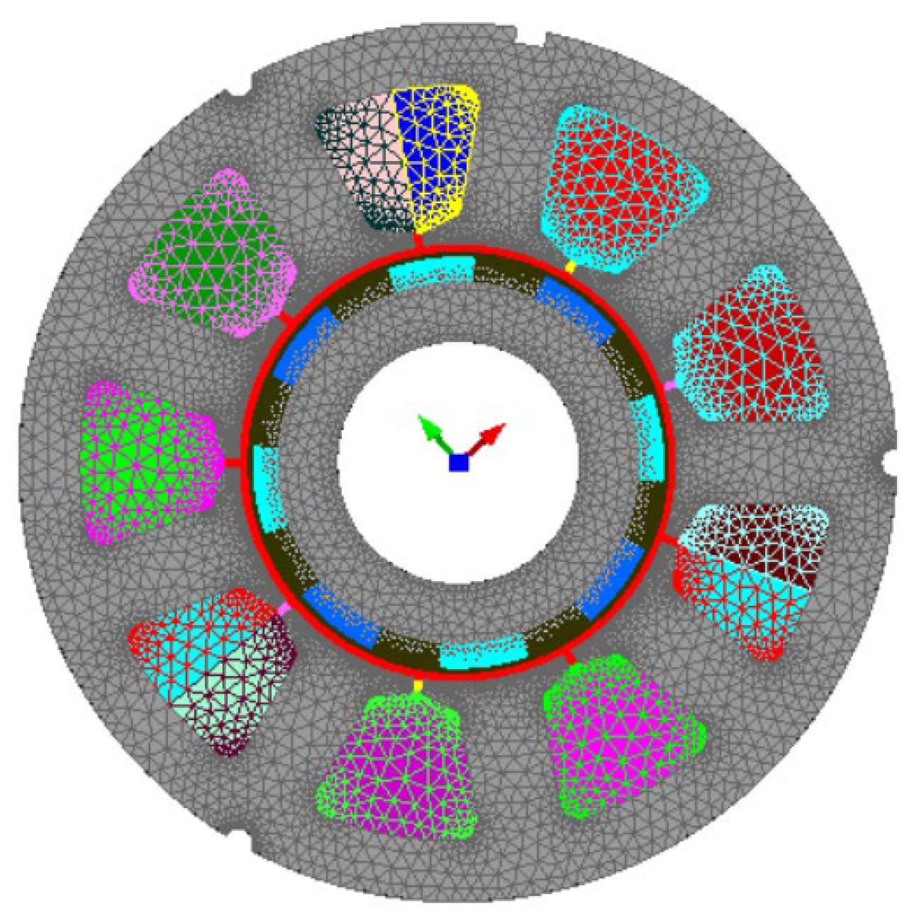
The use of an electrical machine model based on coupled circuits is shown to study the effect of static, dynamic and mixed eccentricity. It is a three-phase star-connected PMSM, with magnets mounted on the rotor surface. The machine has a fractional number of slots per pole per phase structure with eight poles and nine slots, as shown in Figure 5a). To consider the effect of eccentricity on the machine, a database was created with the help of FEA, simulating the machine with 49 different coordinates of the rotor center between −0.3 mm and 0.3 mm in steps of 0.1 mm to simulate static eccentricity, as shown in Figure 5b. The complete information detailing the test machine is derived from the previous characterization carried out by [28]. Table 1 lists the key parameters and construction aspects. A parameter identification technique based on impedance measurements is used, similar to that described in [29], which allows obtaining precise parameters of the PMSM.
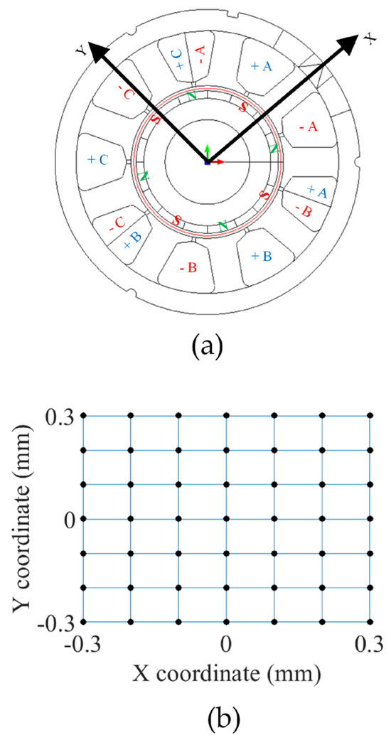
Figure 5.
(a) PMSM used for the study and (b) the rotor center coordinates.

Table 1.
Key parameters and construction aspects for the PMSM.
Figure 6 shows the PMSM in the FEA environment. The meshing was performed using an automatic mesh generator. A relaxation factor can also be specified to densify or disperse the mesh, as shown in the figure.
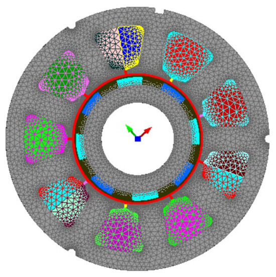
Figure 6.
Geometry and meshing of the PMSM with an FEA model.
The number of mesh nodes has an impact on the computation time and the accuracy of the simulation results. From Figure 6, it is possible to observe the geometry of the machine with an average mesh for most of the surface regions. The air gap has a denser mesh to estimate with better accuracy the captured flux for the stator winding.
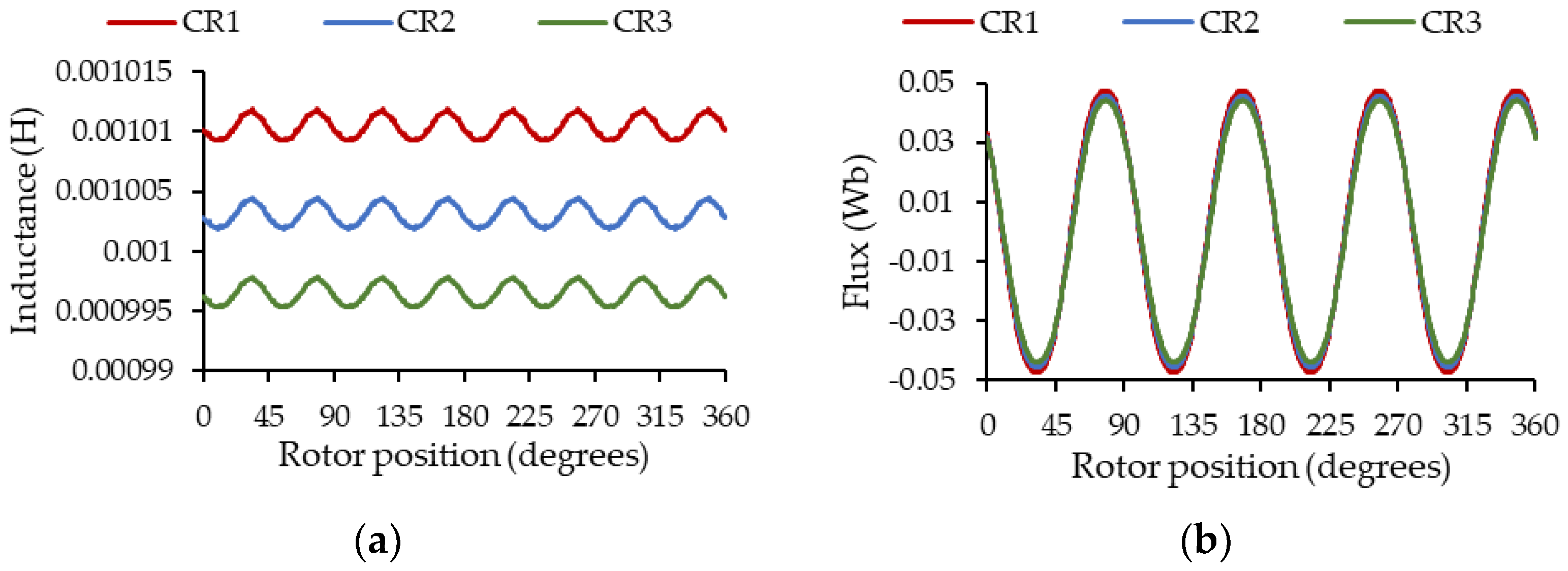
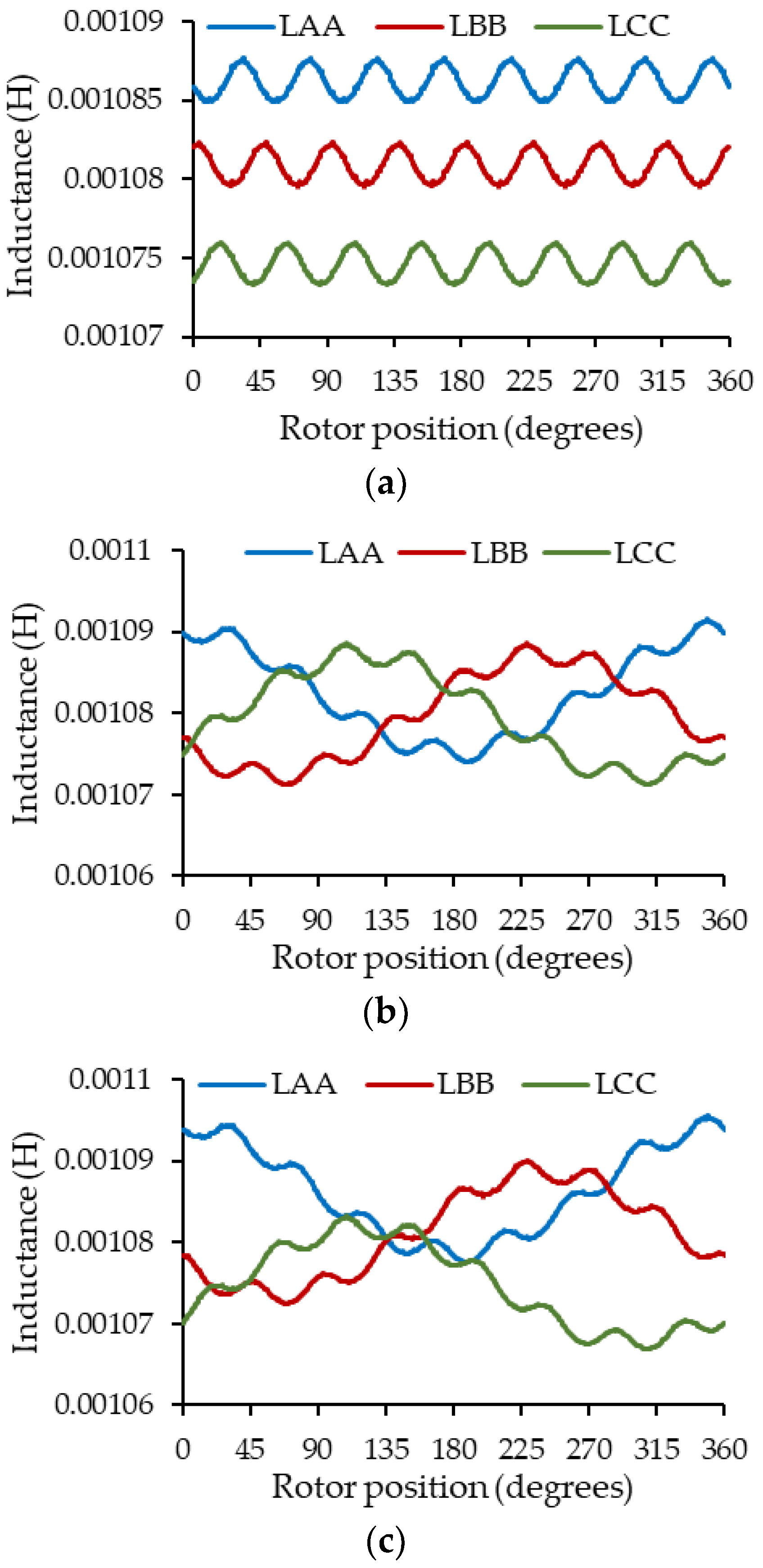
Figure 7 shows the behavior of the self-inductance of phase A and the no-load flow captured by the winding in the same phase in the presence of a static eccentricity when the center of rotation (CR) is CR1: = 0.3 mm and = 0 mm; CR2: = 0 mm and = 0 mm; CR3: = −0.3 mm and = 0 mm.
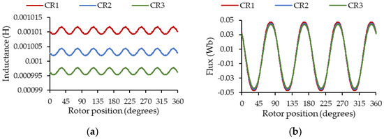
Figure 7.
Parameters of phase A in the presence of static eccentricity as a function of the rotor position for 3 different CR positions. (a) Self-inductance; (b) no-load flow captured by the winding.
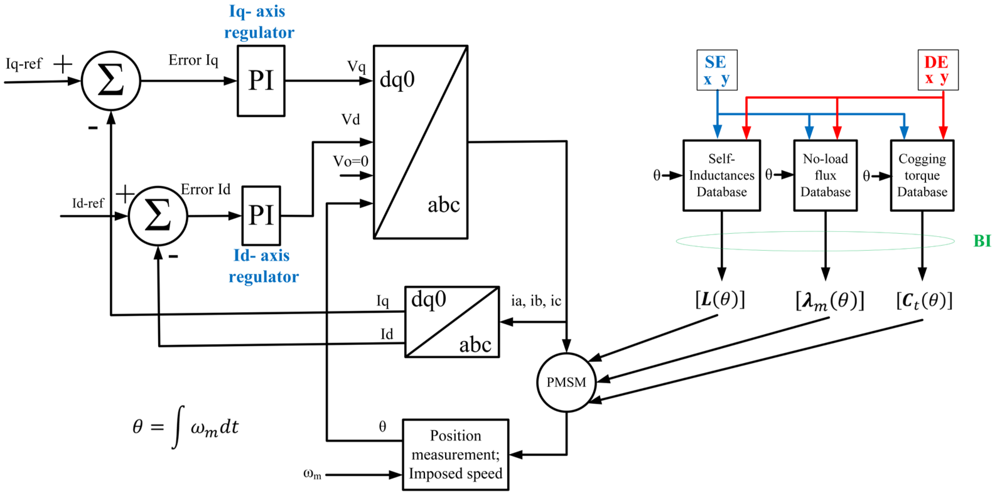
Figure 8 shows the block diagram of the command method implemented for the simulation of the PMSM in the MATLAB/Simulink R2022a environment.

Figure 8.
Block diagram of command method implemented in MATLAB/Simulink.
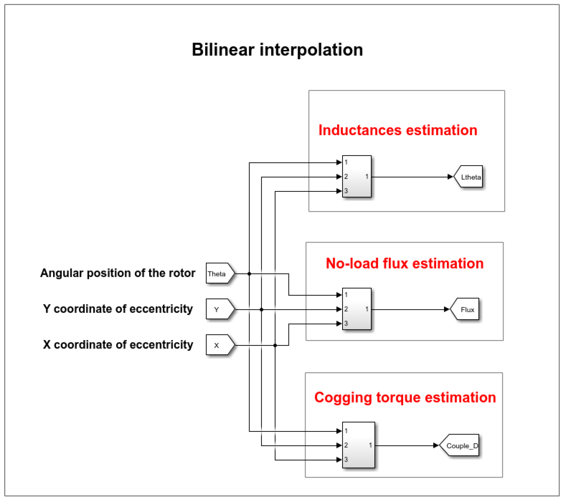
Figure 9 shows the details of the internal blocks in Simulink to carry out bilinear interpolation, the command diagram and the coupled circuit model described in this article.
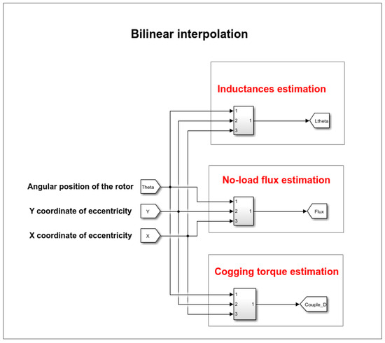
Figure 9.
Bilinear interpolation carried out in the Simulink environment.
In Figure 9, to estimate the PMSM parameters according to the degree of eccentricity and according to the position of the rotor, the bilinear interpolation model is introduced as discussed above. The 49 rotor center positions simulated in the field calculation software are loaded into the MATLAB software R2022a and saved in the workspace. Next, a lookup table is used to evaluate a sampled representation of a function in N variables; in this case, we will have nine lookup tables for all the parameters of the matrix , three lookup tables for the no-load flux vector and one lookup table for the cogging torque . When an input falls outside the range of a breakpoint data set, the block extrapolates the output value from a pair of values at the end of the breakpoint data set. For the bilinear interpolation method, the extrapolation method fits a line between the first or last pair of breakpoints, depending on whether the input is less than the first or greater than the last breakpoint.
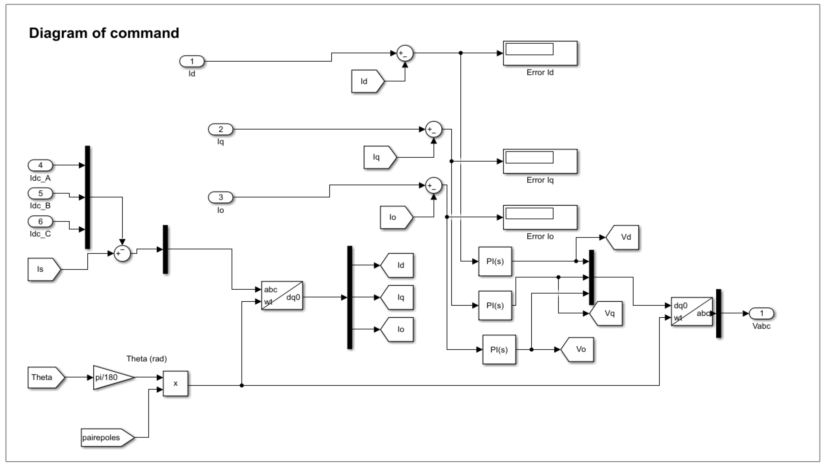
Figure 10 shows the details of the PMSM command diagram in the simulation environment.

Figure 10.
Detail of the PMSM command diagram.
From Figure 10, the PMSM will be controlled by the currents of the axes dq0; therefore we will impose the currents , and in a regulation loop. We can observe the possibility of supplying the machine with a direct current; this is used to simulate the static torque. The angular position of the rotor theta (θ) in degrees is determined according to
An envelopment of cyclic states was considered to take into account the cyclic nature between 0 and 2π of the PMSM. The abc to dq0 block uses a Park transformation to transform a three-phase signal (abc) into a rotating frame dq0. The angular position of the rotating frame is given by the input ωt, in rad.
From the knowledge of the current vector the calculated currents will be
So the error of the control loop is calculated as follows:
A PI compensator for each phase will allow the voltage vector to be calculated. The compensator formula is with and . The dq0 to abc block uses an inverse Park transform to transform a rotating frame dq0 into a three-phase signal (abc).
Finally, the voltage vector is calculated as
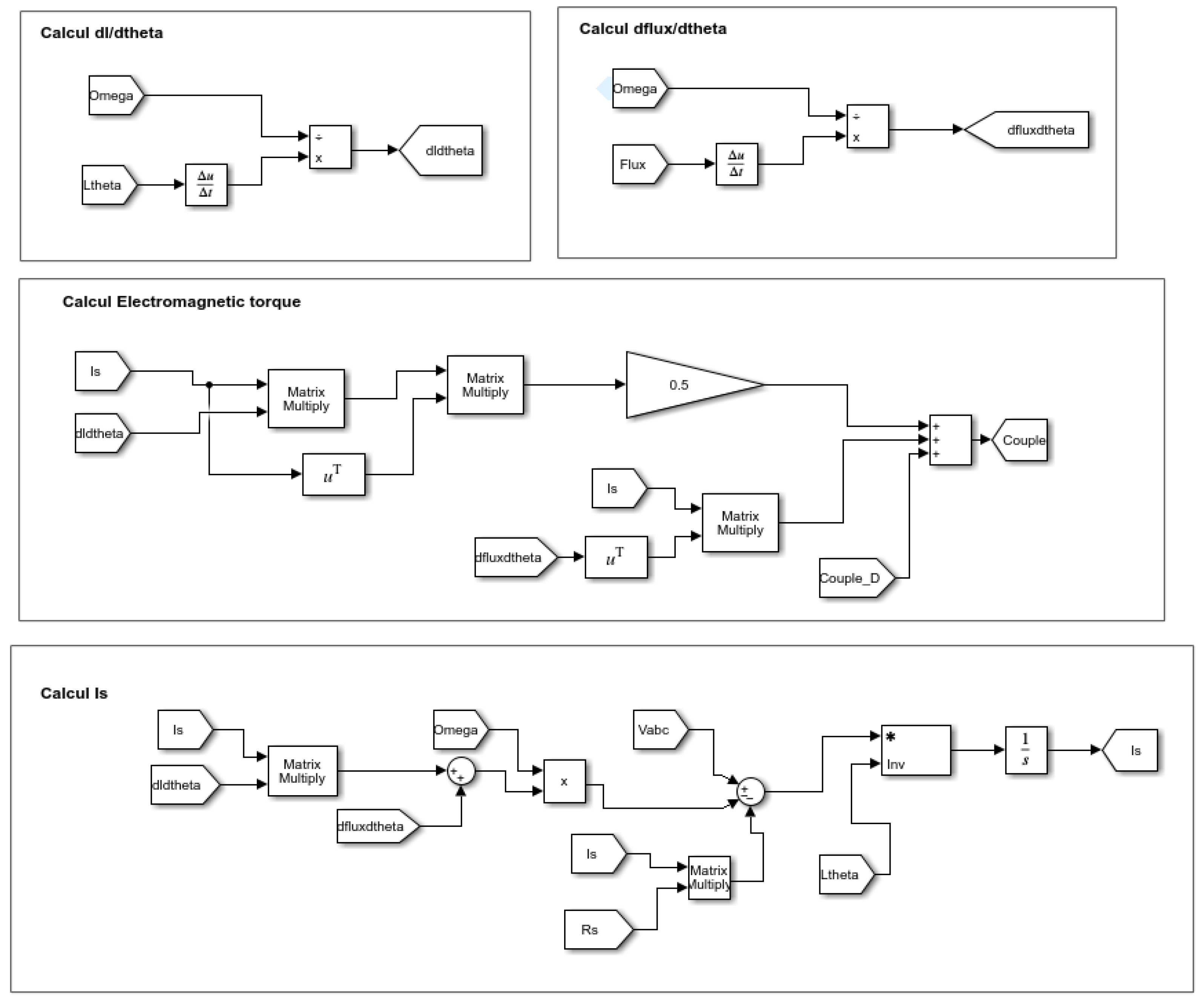
Figure 11 shows the coupled circuit model of the PMSM implemented in Simulink.

Figure 11.
PMSM coupled circuit model in Simulink block diagram.
In Figure 11, Is represents the stator current vector , omega represents the mechanical rotation speed of the machine, Vabc the voltage vector , dfluxdtheta the vector , dldtheta the matrix , Ltheta the matrix and Rs the matrix diagonal . The matrix multiply block allows us to multiply matrices, and the 1/s block is an integrator which allows us to solve the differential equation of currents. is the derivative block which approximates the derivative of the input signal with respect to the simulation time . With this block, we obtain the approximation of by calculating a numerical difference , where is the variation in the input value and is the variation in time since the time step of the previous simulation. Flux represents the vector . The block is a mathematical function that allows us to calculate the transposed matrix of the signal . Couple_D is the cogging torque vector and Couple represents the electromagnetic torque resulting from the PMSM.
6. Results and Discussion
6.1. Validation by Simulated Experimentation
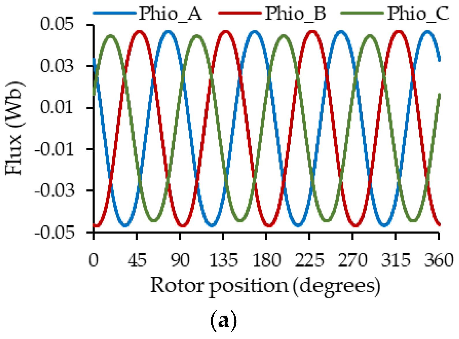
Figure 12 and Figure 13 show the estimation of the self-inductances of the stator windings and the no-load flux captured by them as a function of the rotor position, using the proposed method for the three types of eccentricity with different degrees of severity.
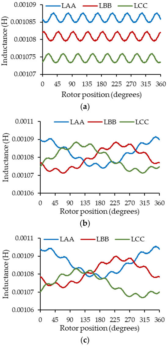
Figure 12.
Self-inductance variations for (a) SE with = −0.15 mm and = 0.1 mm, (b) DE = 0.3 mm, (c) ME: SE with = −0.15 mm and = 0.1 mm + DE = 0.3 mm.
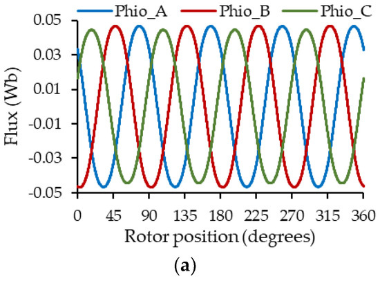
Figure 13.
No-load flux captured by the stator winding results: (a) SE with = −0.15 mm and = 0.1 mm, (b) DE = 0.3 mm, (c) ME: SE with = −0.15 mm and = 0.1 mm + DE = 0.3 mm.
From Figure 12a, we can first observe the effect of static eccentricity on the machine’s self-inductances, which present a variation in their average values. The closer the rotor is to the winding, the greater its coupling and therefore the greater the average value of the inductances, as in the case of the inductances of phase A, where the 0.3 mm of SE were added in the direction of the magnetic axis of phase A. The opposite occurs when the rotor moves away from the winding. Secondly, from Figure 12b, it can be observed that dynamic eccentricity introduces low-frequency oscillations in the self-inductances, caused by the variation in the air gap as the rotor rotates. From Figure 12c, the effect of mixed eccentricity on self-inductances is shown as the combined effect of static and dynamic eccentricity. A behavior like the self-inductances present in dynamic eccentricity can be observed but with a variation in their average values caused by static eccentricity.
From Figure 13, the effect of eccentricity is also present in the no-load flux captured by the winding; for case 13a, a variation in the amplitude of the flux captured by the coils of each phase is observed, being a little more evident for phase C. On the other hand, in Figure 13b,c, slightly low-frequency oscillations appear in the flux captured by the coils. However, for the three cases of eccentricity, these variations follow a behavior like that described in the self-inductances, but it is not very visible.
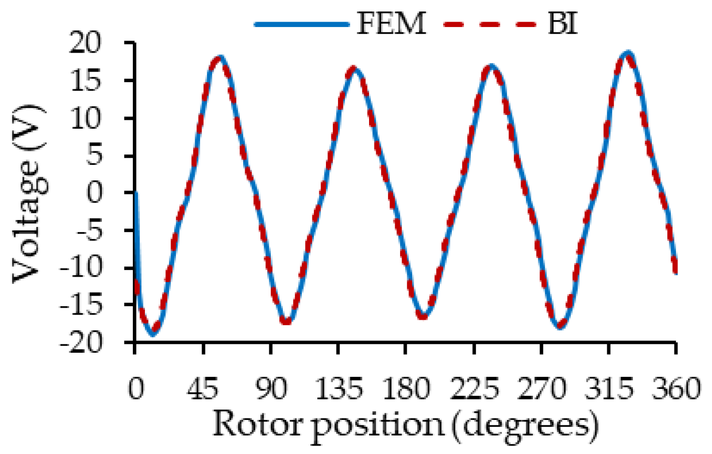
Figure 14 shows a comparison between the proposed fast model and FEA of the phase A voltage when the machine has a dynamic eccentricity of 0.3 mm. The current control is set to Iq = −5 A (generator mode) and Id = 0 A and the machine rotates at 900 rev/min.

Figure 14.
Voltage in phase A of the PMSM for a DE = 0.3 mm.
From Figure 14, it is possible to see that the proposed model can reproduce the voltage per phase. Low-frequency oscillations due to the eccentricity phenomenon are also observable in the voltage of phase to the machine in both simulations.
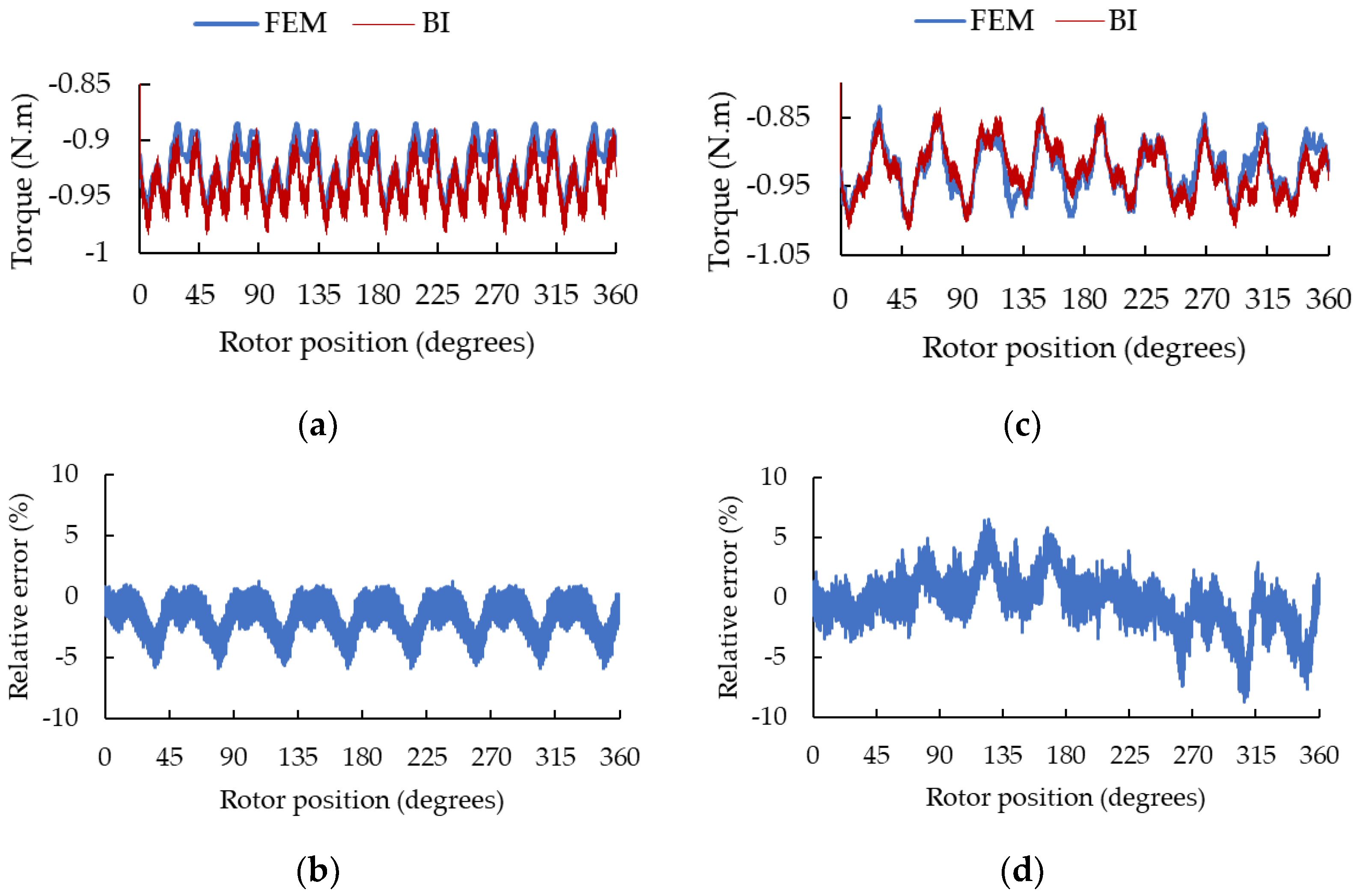
Figure 15 shows the torque developed by the machine with static and dynamic eccentricity when the Iq current is set at −5 amperes (generator mode), the Id current is equal to 0 and the machine rotates at 900 rev/min.

Figure 15.
Torque developed by the PMSM for (a) SE with x = −0.15 mm and y = 0.1 mm. (b) Relative error for SE; (c) DE = 0.3 mm and (d) relative error for DE.
The coupled circuit model parameterizable as a function of eccentricity can reproduce the electromagnetic torque of the PMSM with good precision for SE in Figure 15a and DE in Figure 15c, compared to behavior found using the FEA. A maximum error of 5% for SE in Figure 15b and 8% for DE in Figure 15d can be observed between both characteristics. Those little errors may be associated with the interpolation of the cogging torque due to the presence of permanent magnets. The simulation time necessary to reproduce this scenario for a revolution of the machine using FEA was around 7 min, whereas the fast model developed only took 5 s. This represents a saving in calculation time close to 99%.
6.2. Validation by Practical Experimentation
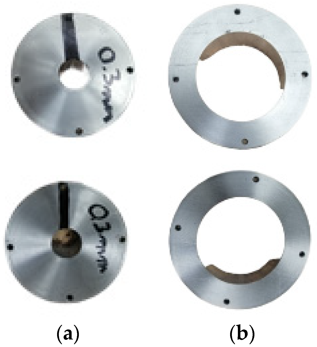
To produce the static eccentricity of the machine, bushings were placed above and below the bearings to move the center of the stator or/and the rotor, similar to what was done in [30]. Added eccentricity in the stator bushings (the outer rings on the bearing) moves the center of the stator and produces a static eccentricity effect. Dynamic eccentricity is obtained by adding eccentricity on the inner bushings, under the bearings. These parts produce a variation in the air gap that varies according to the angular position of the rotor. Finally, to produce a mixed eccentricity effect, outer rings and inner rings with eccentricity must be used. Figure 16 presents outer and inner bushings.
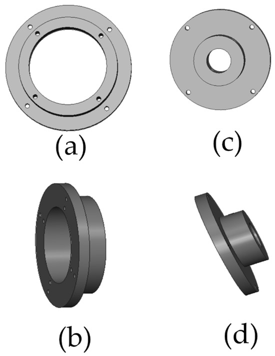
Figure 16.
Bushings to produce static eccentricity. (a) Front view, (b) side view and dynamic eccentricity (c) front view, (d) side view.
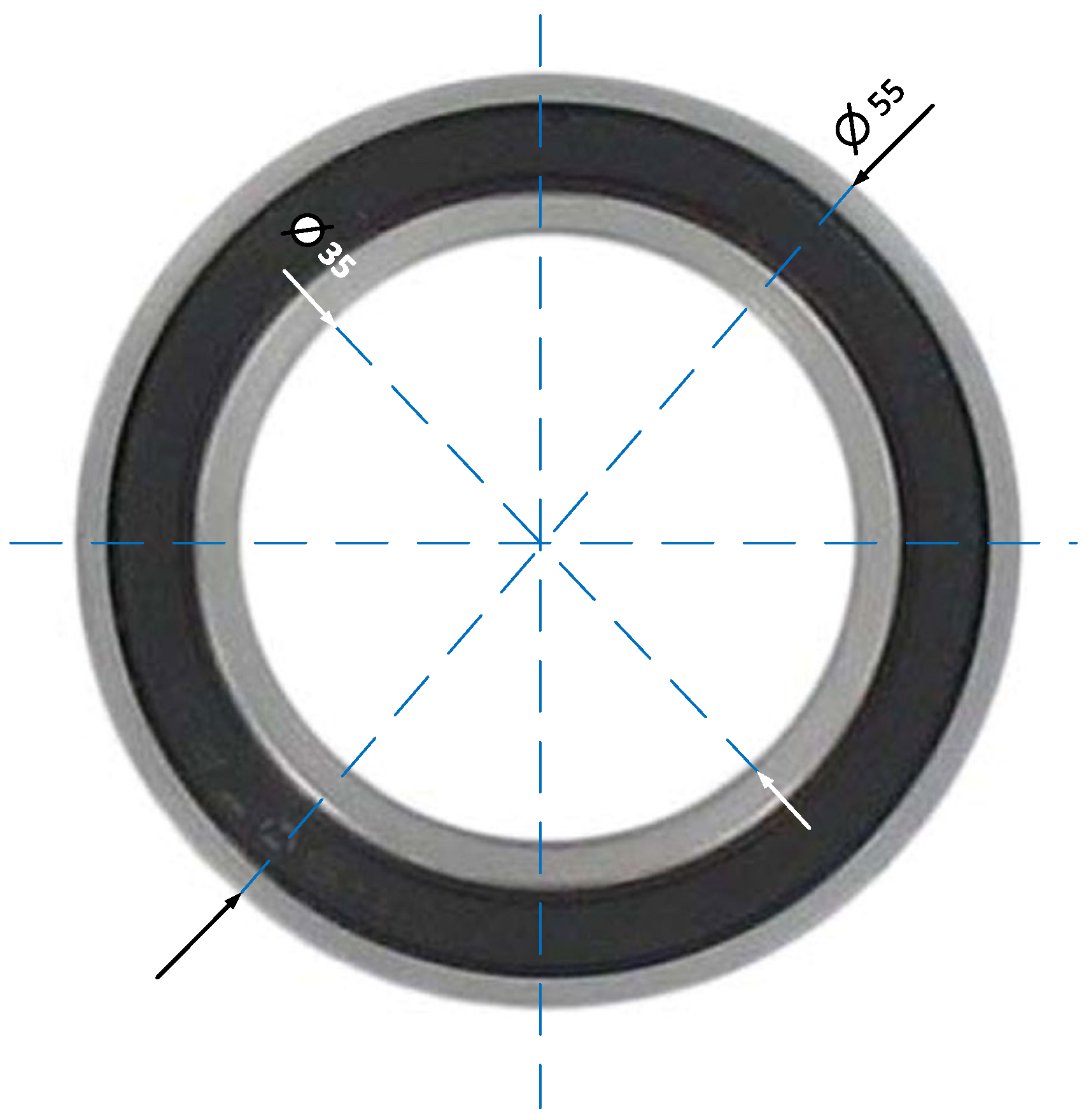
Figure 17 shows the new bearing that will be used for the study of eccentricity in our PMSM. The dimensions of this bearing are inner diameter 35 mm, outer diameter 55 mm and thickness 10 mm.
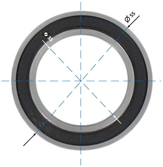
Figure 17.
Bearing for the study of eccentricity.
In DE fault, the minimum length of the air gap depends on the angular position of the rotor and rotates around the rotor. In this eccentricity, the axis of symmetry of the stator and the axis of rotation of the rotor are the same, but the axis of symmetry of the rotor has been displaced.
To produce DE, it is necessary to act on the inner ring. One way to do this is to modify the center of the inner circle of the ring without modifying the center of the outer circle, as shown in Figure 18 for a DE of 0.3 mm.
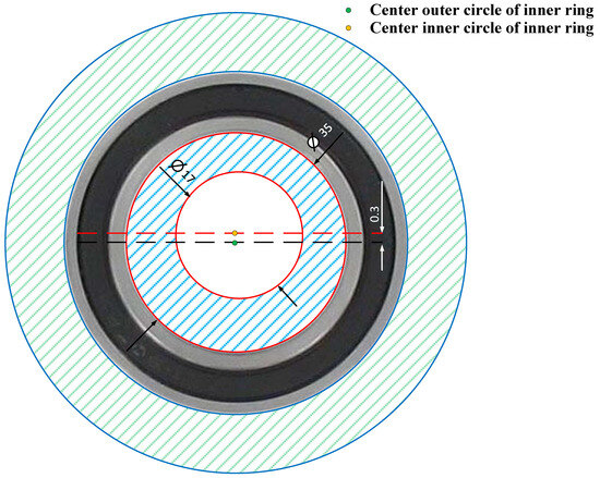
Figure 18.
Production of a dynamic eccentricity of 0.3 mm in the PMSM.
A DE of 0.3 mm was introduced into the machine, and the bushings fixed to the rotor and stator are shown in Figure 19 and Figure 20.
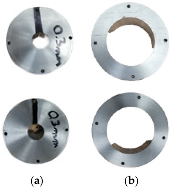
Figure 19.
(a) Rotor bushings and (b) stator bushings producing a dynamic eccentricity of 0.3 mm.
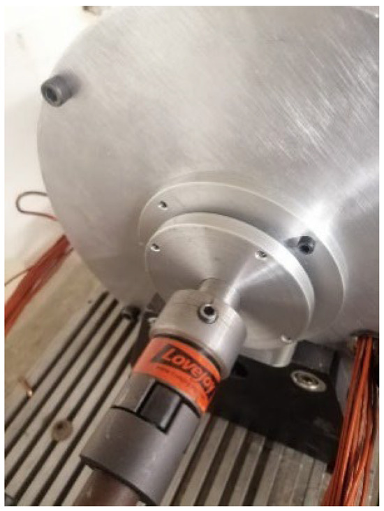
Figure 20.
PMSM with a 0.3 mm dynamic eccentricity fault.
The dynamic eccentricity is produced by the rotor bushing, separating the center of symmetry of the rotor (OR) from the center of symmetry of the stator (OS) and from the center of rotation (OW).
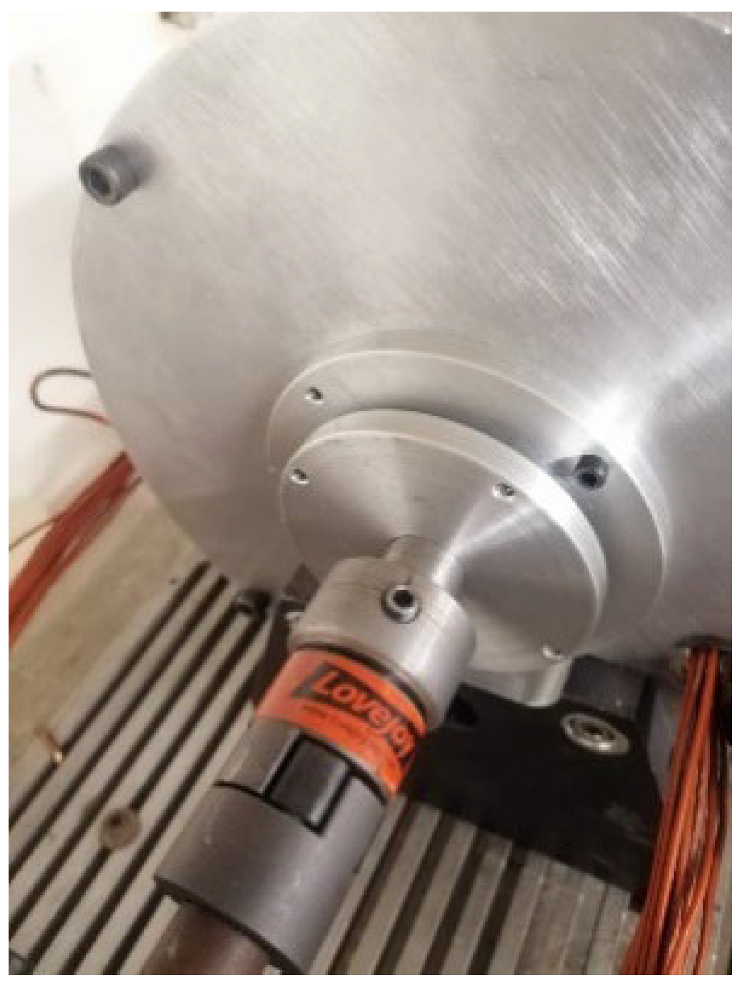
The PMSM was mechanically coupled to a speed-controlled test bench with a gearbox to allow low speeds on the test machine. Once the speed was imposed on the machine shaft, a direct current of 5.31 A was applied between phases A and B of the machine and the static torque of the machine, and the angular position of the rotor was recorded analogically using an oscilloscope. Figure 21 shows the scheme of the experiment carried out.
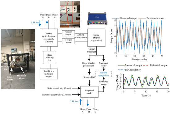
Figure 21.
Block diagram of the experiment carried out.
To compare the practical results with the developed model, signal treatment was applied to the signal recordings to eliminate the presence of noise. As the mechanical speed (Ω) was imposed in the model, it was determined as follows:
Figure 22 shows the machine speed during the test, calculated using (26).
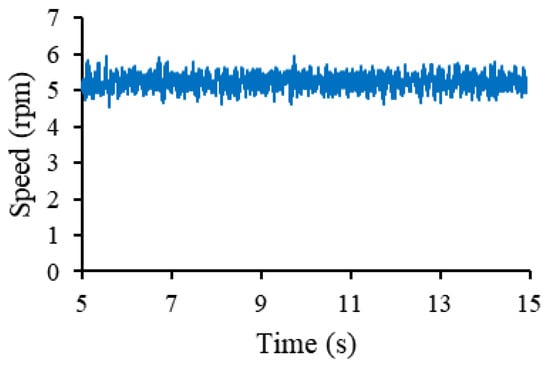
Figure 22.
PMSM speed during the experiment carried out.
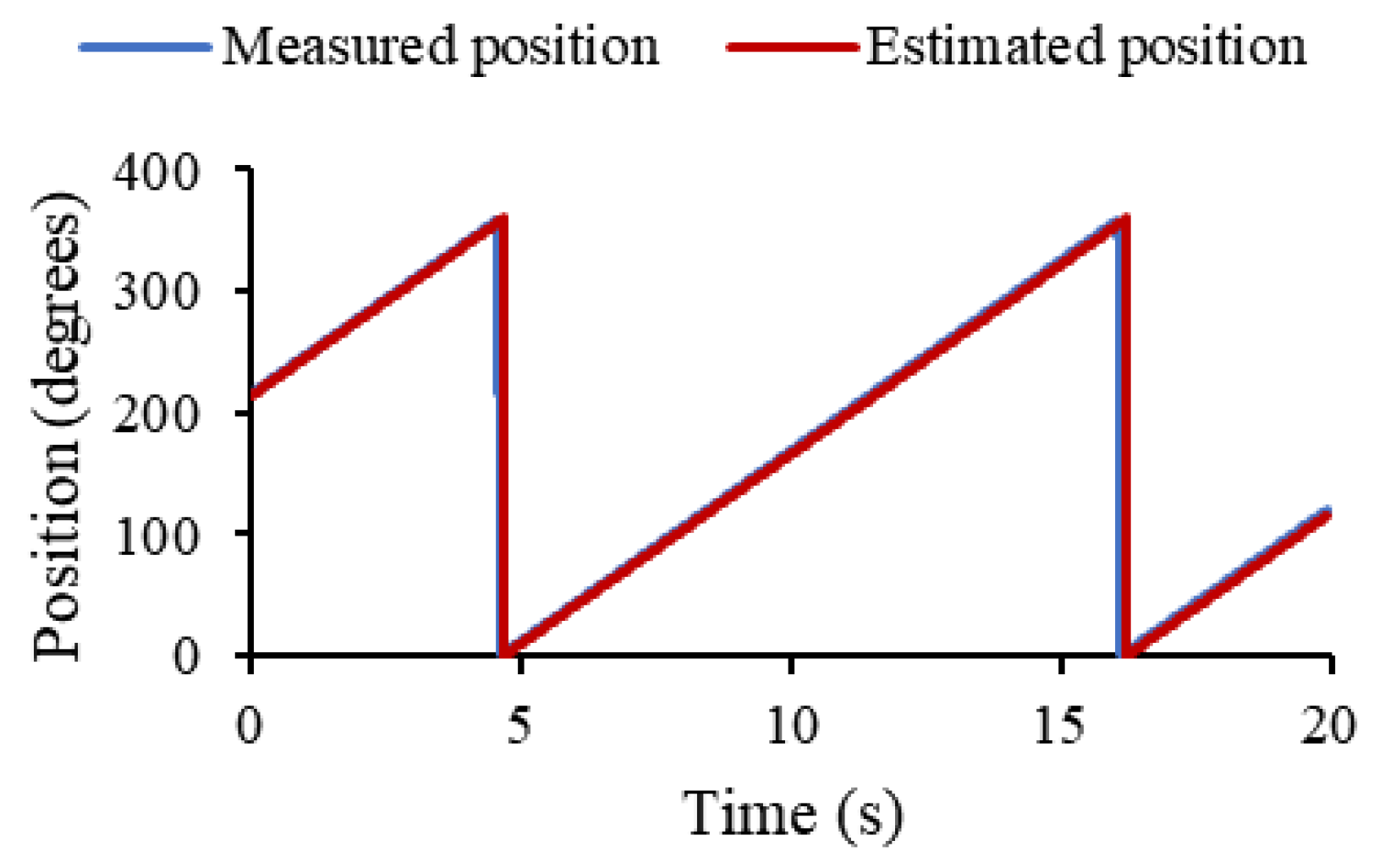
The average speed of the test was 5.2 rev/min, a value that was imposed in the model. To validate this, the estimated rotor angular position and that measured in the experiment were compared as shown in Figure 23, observing a superposition of the curves.
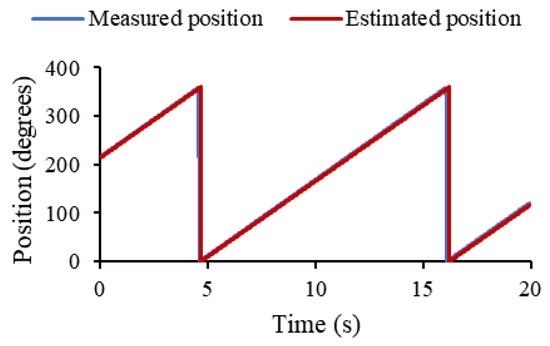
Figure 23.
Measured rotor angular position and rotor angular position estimated by the proposed model.
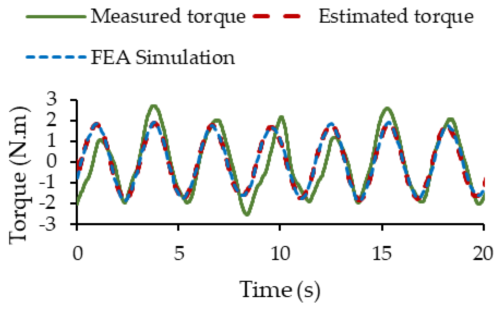
Figure 24 presents a comparison between the static torque measured experimentally in the laboratory and the static torque obtained from the proposed model of the PMSM. The presence of noise is observed in the measured torque, which is expected in experimental measurements of this type.
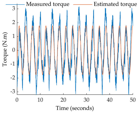
Figure 24.
Comparison between the static torque measured experimentally and the static torque obtained from the model proposed.
Despite the presence of noise, it is possible to observe a general agreement between both curves, which validates the accuracy of the model for representing the motor behavior under static conditions. The characteristic periodic behavior of the PMSM is remarkable, with variations in the couple and appreciating its maximum and minimum points, as well as the general shape of the wave, which resembles a sinusoid with low-frequency oscillations due to the presence of the dynamic eccentricity fault.
To mitigate the effect of noise on the measurements and obtain a clearer signal, a moving average filter was applied to the measured static couple data. This filter allows us to reduce random fluctuations in the signal and highlight the general trend, facilitating comparison with the proposed model. The statistical results are shown in Table 2.
Table 2.
Statistical results of the comparison of the signal measured with noise and without noise with respect to the signal obtained from the proposed model.
The improvement in RMSE and R2 after applying the moving average filter suggests that noise was contributing in some way to the discrepancies between the proposed model and laboratory measurements. The reduction in noise has resulted in a better fit and a more accurate representation of the PMSM dynamics. With R2 of 0.75 the model explains 75% of the variability observed in the measured static torque data, which represents a significant portion of the motor dynamics. However, it also indicates that there is 25% of the variability that is not explained by the model. Figure 25 shows the static torque measured in practice after filtering, the static torque in FEA simulation and the static torque estimated by the proposed model when the PMSM has a dynamic eccentricity of 0.3 mm.
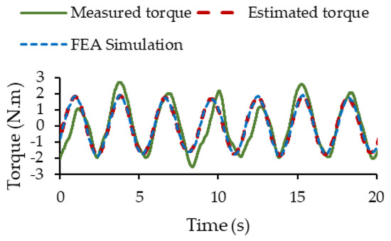
Figure 25.
Measured static torque and estimated static torque by the proposed model.
Figure 25 shows a superposition of the characteristic obtained with the proposed fast model and FEA, which validates the proposed fast model through simulated experimentation. Although good overall agreement is observed, small differences can be seen between the two curves, especially at each half-cycle of rotor rotation. Some important gaps are shown with respect to laboratory measurements. In the second peak of the curve, a maximum difference of around 0.8 N.m can be observed, as well as other lighter ones (less than 0.5 N.m) in the rest of the curve. These differences may be caused by the test bench used, considering that the machine used in this test is a prototype manufactured in the laboratory. There are also various mechanical plays in the strain gauge that could add error or increase variations. The presence of low-frequency oscillations in the torque can be observed, a characteristic associated with the presence of a dynamic eccentricity of the PMSM.
7. Conclusions
In this article, a fast model for PMSM with the presence of static, dynamic and mixed eccentricity was proposed. The proposed model is capable of accurately reproducing the behavior of the machine with a saving in computational time close to 99% compared to the simulation time found using FEA. This saving of simulation time allows us to explore in detail the effect of eccentricity on other variables of interest in the machine, such as current, voltage and torque waveforms. Furthermore, the proposed model was able to accurately reproduce the static torque of the practical experience carried out with the machine, presenting a dynamic eccentricity of 0.3 mm.
Using rapid models, it is possible to identify the most sensitive parameters facing the presence of static, dynamic and mixed eccentricity and to build a detailed database. This is the first step to develop diagnostic strategies capable of detecting, identifying and determining the severity of an eccentricity fault in the electrical machine.
Author Contributions
Conceptualization, R.P. and J.C.; methodology, R.P. and J.C.; software, R.P.; validation, R.P. and J.C.; formal analysis, R.P.; investigation, R.P.; resources, R.P. and J.C.; data curation, R.P.; writing—original draft preparation, R.P.; writing—review and editing, all authors.; visualization, R.P.; supervision, J.C. and M.P.; project administration, J.C. and M.P.; funding acquisition, J.C. and M.P. All authors have read and agreed to the published version of the manuscript.
Funding
This research received no external funding.
Data Availability Statement
Data are contained within the article.
Conflicts of Interest
The authors declare no conflicts of interest.
References
- Chen, Y.; Liang, S.; Li, W.; Liang, H.; Wang, C. Faults and Diagnosis Methods of Permanent Magnet Synchronous Motors: A Review. Appl. Sci. 2019, 9, 2116. [Google Scholar] [CrossRef]
- Kia, M.Y.; Khedri, M.; Najafi, H.R.; Nejad, M.A.S. Hybrid modelling of doubly fed induction generators with inter-turn stator fault and its detection method using wavelet analysis. IET Gener. Transm. Distrib. 2013, 7, 982–990. [Google Scholar] [CrossRef]
- Ishikawa, T.; Seki, Y.; Kurita, N. Analysis for fault detection of vector-controlled permanent magnet synchronous motor with permanent magnet defect. IEEE Trans. Magn. 2013, 49, 2331–2334. [Google Scholar] [CrossRef]
- Wang, C.; Wang, M.; Yang, B.; Song, K.; Zhang, Y.; Liu, L. A novel methodology for fault size estimation of ball bearings using stator current signal. Measurement 2021, 171, 108723. [Google Scholar] [CrossRef]
- Ebrahimi, B.M.; Roshtkhari, M.J.; Faiz, J.; Khatami, S.V. Advanced Eccentricity Fault Recognition in Permanent Magnet Synchronous Motors Using Stator Current Signature Analysis. IEEE Trans. Ind. Electron. 2014, 61, 2041–2052. [Google Scholar] [CrossRef]
- Xu, X.; Han, Q.; Chu, F. Review of electromagnetic vibration in electrical machines. Energies 2018, 11, 1779. [Google Scholar] [CrossRef]
- Wang, Y.; Liu, K.; Hua, W.; Zhang, C.; Wu, Z.; Zhang, H. Analysis and Detection of Rotor Eccentricity in Permanent Magnet Synchronous Machines Based on Linear Hall Sensors. IEEE Trans. Power Electron. 2022, 37, 4719–4729. [Google Scholar] [CrossRef]
- Ebrahimi, B.M.; Faiz, J.; Nejhad, A.Z. Static Eccentricity Fault Diagnosis in Permanent Magnet Synchronous Motor Using Time Stepping Finite Element Method. IEEE Trans. Magn. 2008, 44, 4297–4300. [Google Scholar] [CrossRef]
- Abdelli, R.; Bouzida, A.; Touhami, O.; Ouadah, M. Static eccentricity fault modeling in permanent-magnet synchronous motors. In Proceedings of the 2016 8th International Conference on Modelling, Identification and Control (ICMIC), Algiers, Algeria, 15–17 November 2016; IEEE: Piscataway, NJ, USA, 2017; pp. 364–368. [Google Scholar] [CrossRef]
- Singh, A.; Grant, B.; Defour, R.; Sharma, C.; Bahadoorsingh, S. A review of induction motor fault modeling. Electr. Power Syst. Res. 2016, 133, 191–197. [Google Scholar] [CrossRef]
- Liu, Z.; Zhang, P.; He, S.; Huang, J. A review of modeling and diagnostic techniques for eccentricity fault in electric machines. Energies 2021, 14, 4296. [Google Scholar] [CrossRef]
- Ebrahimi, B.M.; Faiz, J.; Roshtkhari, M.J. Static-, dynamic-, and mixed-eccentricity fault diagnoses in permanent-magnet synchronous motors. IEEE Trans. Ind. Electron. 2009, 56, 4727–4739. [Google Scholar] [CrossRef]
- Goktas, T.; Zafarani, M.; Akin, B. Discernment of Broken Magnet and Static Eccentricity Faults in Permanent Magnet Synchronous Motors. IEEE Trans. Energy Convers. 2016, 31, 578–587. [Google Scholar] [CrossRef]
- Tavana, N.R.; Dinavahi, V. Real-Time FPGA-Based analytical space harmonic model of permanent magnet machines for hardware-in-the-loop simulation. IEEE Trans. Magn. 2015, 51, 8106609. [Google Scholar] [CrossRef]
- Scheer, R.; Bergheim, Y.; Aleff, S.; Heintges, D.; Rahner, N.; Gries, R.; Andert, J. A Virtual Prototyping Approach for Development of PMSM on Real-Time Platforms: A Case Study on Temperature Sensitivity. Automot. Innov. 2022, 5, 285–298. [Google Scholar] [CrossRef]
- Kang, K.; Song, J.; Kang, C.; Sung, S.; Jang, G. Real-Time Detection of the Dynamic Eccentricity in Permanent-Magnet Synchronous Motors by Monitoring Speed and Back EMF Induced in an Additional Winding. IEEE Trans. Ind. Electron. 2017, 64, 7191–7200. [Google Scholar] [CrossRef]
- Lee, H.K.; Shin, K.H.; Bang, T.K.; Nah, J.H.; Choi, J.Y. Experimental Verification and Analytical Study of Influence of Rotor Eccentricity on Electromagnetic Characteristics of Permanent Magnet Machine. IEEE Trans. Appl. Supercond. 2020, 30, 5202605. [Google Scholar] [CrossRef]
- Liu, F.; Xiang, C.; Liu, H.; Chen, X.; Feng, F.; Cong, H.; Yu, K. Model and experimental verification of a four degrees-of-freedom rotor considering combined eccentricity and electromagnetic effects. Mech. Syst. Signal Process. 2022, 169, 108740. [Google Scholar] [CrossRef]
- Gong, Z.; Desenfans, P.; Pissoort, D.; Hallez, H.; Vanoost, D. Multiphysics Coupling Model to Characterise the Behaviour of Induction Motors with Eccentricity and Bearing Faults. IEEE Trans. Energy Convers. 2023, 39, 146–159. [Google Scholar] [CrossRef]
- Montonen, J.; Nerg, J.; Gulec, M.; Pyrhönen, J. A new traction motor system with integrated-gear: A solution for off-road machinery. IEEE Access 2019, 7, 113740–113750. [Google Scholar] [CrossRef]
- Momen, F.; Rahman, K.; Son, Y. Electrical propulsion system design of chevrolet bolt battery electric vehicle. IEEE Trans. Ind. Appl. 2019, 55, 376–384. [Google Scholar] [CrossRef]
- Usman, A.; Joshi, B.M.; Rajpurohit, B.S. Review of fault modeling methods for permanent magnet synchronous motors and their comparison. In Proceedings of the International Symposium on Diagnostics for Electrical Machines, Power Electronics and Drives, Tinos, Greece, 29 August–1 September 2017; pp. 141–146. [Google Scholar]
- Vaseghi, B.; Takorabet, N.; Meibody-Tabar, F. Fault analysis and parameter identification of permanent-magnet motors by the finite-element method. IEEE Trans. Magn. 2009, 45, 3290–3295. [Google Scholar] [CrossRef]
- Fitouri, M.; Bensalem, Y.; Abdelkrim, M.N. Analysis and co-simulation of permanent magnet sychronous motor with short-circuit fault by finite element method. In Proceedings of the 13th International Multi-Conference on Systems, Signals and Devices, SSD, Leipzig, Germany, 21–24 March 2016; IEEE: Piscataway, NJ, USA, 2016; pp. 472–477. [Google Scholar]
- Usman, A.; Rajpurohit, B.S. Condition monitoring of a surface mounted permanent magnet-type brushless direct current motor using remodelling of rotor magnetic field and stator winding inductance. IET Electr. Syst. Transp. 2021, 11, 81–98. [Google Scholar] [CrossRef]
- Usman, A.; Rajpurohit, B.S. Development of an online condition monitoring based system for the partial demagnetization fault diagnosis of SPM-type BLDC motor. Energy Convers. Econ. 2022, 3, 72–84. [Google Scholar] [CrossRef]
- Krause, P.; Wasynczuk, O.; Sudhoff, S.; Pekarek, S. Analysis of Electric Machinery and Drive Systems; IEEE Press: Piscataway, NJ, USA, 2013; ISBN 9781118024294. [Google Scholar]
- Kakhki, T. Modeling of Losses in a Permanent Magnet Machine Fed by a PWM Supply. Ph.D. Thesis, Laval University, Quebec City, QC, Canada, 2016. [Google Scholar]
- Aboubi, F.Z.; Maïga, A.; Cros, J.; Kamwa, I. Experimental Identification of a Coupled-Circuit Model for the Digital Twin of a Wound-Rotor Induction Machine. Energies 2024, 17, 1948. [Google Scholar] [CrossRef]
- Shin, J.; Park, Y.; Lee, S. Bin Flux-Based Detection and Classification of Induction Motor Eccentricity, Rotor Cage, and Load Defects. IEEE Trans. Ind. Appl. 2021, 57, 2471–2480. [Google Scholar] [CrossRef]


Disclaimer/Publisher’s Note: The statements, opinions and data contained in all publications are solely those of the individual author(s) and contributor(s) and not of MDPI and/or the editor(s). MDPI and/or the editor(s) disclaim responsibility for any injury to people or property resulting from any ideas, methods, instructions or products referred to in the content. |
© 2025 by the authors. Licensee MDPI, Basel, Switzerland. This article is an open access article distributed under the terms and conditions of the Creative Commons Attribution (CC BY) license (https://creativecommons.org/licenses/by/4.0/).