Abstract
Due to complex environmental factors, the gear transmission systems of wind turbines are continuously affected by large torque load excitation with periodic and random properties. This paper shares the load-sharing and dynamic characteristics of a herringbone planetary gear system applied in a wind turbine. The gear dynamic model is established using a typical lumped parameter method, in which the nonlinear transmission errors of the gear pairs and left and right-side coupling stiffness of the herringbone gears are included. With the help of the blade element momentum theory, the precise calculation of the hub load of the wind turbine, which is the external excitation of the gear system, is implemented, in which the wind shear, tower shadow, turbulent effect, and tip loss correction are taken into consideration. The nonlinear dynamic characteristics of the system are obtained using the Runge-Kutta method and then discussed. The results show that the turbulent effect plays a major role in the impact on the load-sharing characteristics, and a reasonable set of the support stiffness of rotational components can improve the load-sharing characteristics of the system. The purpose of this research is to provide some useful references in numerical modelling and methods for designers and researchers of wind turbine transmission systems.
1. Introduction
Currently, herringbone planetary gear systems have been developed and widely applied in wind turbine, aero-engine, helicopter propeller, and ship propeller transmission systems because of their excellent carrying capacity. In wind power engineering applications, the stability of the gear transmission system is always the focus of research because of the complex and changeable external environmental load. Therefore, the load analysis and dynamic characteristics of planetary transmission systems have been widely studied in the past thirty years. The research of early scholars focused on the linear modelling of the gear transmission system and the effect of the fixed value excitation on the dynamic characteristics [1,2,3]. At the same time, experimental and measurement techniques of planetary gear dynamics had been developed to some extent [4,5]. Some interesting mechanisms and features of dynamics can be revealed and found using the nonlinear dynamic theory with the discovery of experiments and the development of dynamics. Thus, many experts have begun to pay attention to the nonlinearity of the system and the influence of internal/external excitation nonlinearity.
Gou et al. [6] focused on the nonlinear effect of a planetary gear system of a wind turbine caused by gravity. Through the nonlinear dynamic model, including the gravity, time-varying meshing stiffness, clearance of the bearing, and nonlinear contact of the tooth surface, a source of planetary bearing failures and its solution strategy were discovered. Zhao et al. [7] studied the nonlinear vibration features of a gear system with different pitting faults. Xiang et al. [8] and Zhang et al. [9] revealed the crack and wear failure mechanisms of a multi-stage gear transmission system of a wind turbine, respectively. Zhao et al. [10] analyzed the effect of transmission error on the planetary gear system of a wind turbine using a multi-gap gear finite element model. Because of the heavy load capacity of the herringbone gear, this structure was developed and applied to wind turbines. Currently, there are many outstanding scholars who have made outstanding contributions to the dynamic research of herringbone planetary gear. Mo et al. [11,12,13] conducted a series of investigations on a herringbone planetary gear system to reveal the influence of different structural parameters on the system’s dynamic characteristics. Wang et al. [14] and Hou et al. [15] investigated the effect of a flexible pin and friction excitation on a herringbone planetary gear system using the finite element method. Wang et al. [16] presented a herringbone planetary gearbox failure model in a wind turbine to reveal the pitting failure mechanism. The results of the research indicated that precise predictions could be obtained using the description of precise excitation considered in the dynamic model. Xu et al. [17] investigated the nonlinear behavior of herringbone planetary gear transmission systems with double-sided meshing impact and found that reducing the backlash ensured stable system operation. Wang [18] established the relationship between transmission system characteristics and gear modification. The optimum modification parameters of the axial and tooth shape were determined, which could achieve the purpose of vibration and noise reduction. Wu et al. [19] investigated the dynamic characteristics of a herringbone gear system with uncertain parameters. Although there are plenty of excellent studies on the nonlinear dynamic characteristics of herringbone planetary gear systems, dynamics research on herringbone planetary gear systems were applied to wind turbines. In addition, the external load of a wind turbine gearbox in service is more complex than that of the general gearbox. In actual wind power engineering, the load acting on the hub, which is the external excitation of the gear transmission system, has strong periodicity and randomness because of the wind field atmospheric environment and wind turbine structure itself, especially turbulent wind.
Thus, actual wind load and time-varied load excitation have gradually gained the attention of researchers. Chen et al. [20] presented a multi-source external environmental load modelling method and investigated resonance identification and dynamic responses under electromechanical coupling conditions. Wang et al. [21] studied the dynamic characteristics of both conventional and compact wind turbine gearboxes, including load-sharing and fatigue damage assessment. Tan et al. [22,23] performed a series of developments on an external environmental load acting on a gear transmission system of a wind turbine, revealing the effect of complex load conditions on the system, such as the voltage dip and platform motion and time-varying wind load. Abo et al. [24] presented a turbulent wind speed model under different influence factors, including wind shear, tower shadow, and turbine inertia. Wang et al. [25] articulated the modelling of wind and wave coupling for a floating wind turbine drivetrain. Porté-Agel et al. [26] summarized recent experimental, computational, and theoretical research efforts for wind farm prediction. Doagou et al. [27] established an erosion model of a wind turbine blade, fully considering random liquid impact. Da Silva et al. [28] studied the nonlinear dynamics of a floating offshore wind turbine, considering turbulent wind and irregular waves and focusing on the natural frequency of the system during surges. Bangga et al. [29,30] established an aerodynamic model of a wind turbine load to obtain the exact load of the system using the CFD and BEM methods under different wind conditions. The randomness of wind speed can be precisely described using the above studies. However, the calculation of hub load is mostly simplified using an approximate expression according to the Bates theory, and wind farm environments, blades, the wind shear effect, and the tower shadow effect were also ignored. As a consequence, the periodicity of the hub load was inexact.
Therefore, on the basis of the literature review above, the description of the precise hub load of a wind turbine is the first purpose of this paper. A calculation model of the hub load is established using the blade element momentum theory (BEM), which includes the wind shear effect, tower shadow effect, and turbulent effect. The coordinate transformation method is used to describe the wind speed uniformly at different locations. At the same time, the second purpose is to emphasize the importance of the turbulent wind condition in herringbone planetary gear modelling and dynamic characteristics. Furthermore, it is also one of the purposes of this paper to find out the cause of the fluctuation of the system’s dynamic characteristics in the external excitation and analyze the solution. It is hoped that this research can provide some useful reference for the design and manufacture of the herringbone planetary gear systems of wind turbines.
2. Modeling and Theories
2.1. Research Framework and Assumption
In this study, a herringbone planetary gear transmission system of a megawatt wind turbine was employed as the object of this study. The key elements of this study are shown in Figure 1, which mainly includes different wind conditions, an impeller, and a gear system. In the process of modeling, the key elements can be simplified into three subsystem models, called the wind velocity model, the load calculation model of the hub, and the dynamic model of the herringbone planetary gear system. Firstly, the turbulent wind can be calculated, involving the wind shear effect, tower shadow effect, and turbulent effect. Then, the hub load can be calculated as the turbulent wind load based on the BEM. Finally, the dynamic characteristics can be acquired using the dynamic model of a herringbone planetary gear transmission system considering the exact input load.
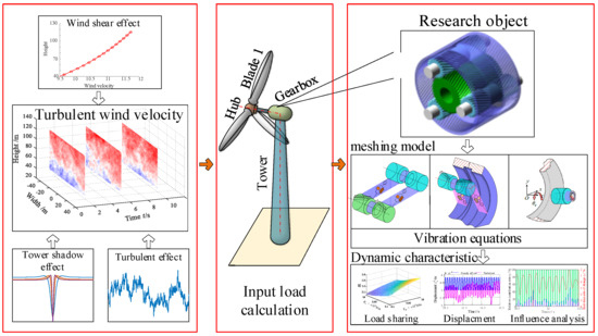
Figure 1.
Overall research framework diagram.
The assumptions for a dynamics model of a herringbone planetary gear system are as follows:
The input torque is directly loaded onto the planetary carrier. The herringbone gear system is considered to be a combination of two helical gear systems. The planetary gears are evenly arranged, and each member is rigid. The cross-angle of the herringbone gears due to manufacturing errors is not considered. The support bearing is reduced to a spring damping system. In this study, 4.5 m/s was the cut-in wind velocity, and the cut-out wind velocity was set to 25 m/s. The rated wind speed of the impeller of a wind turbine was 12 m/s.
2.2. A Dynamic Model of the Gear System
2.2.1. Motion Equations
A dynamic model of the planetary gear dynamics model in the OXY plane is shown in Figure 2. There were three kinds of coordinate systems. The motions of all parts of the hybrid wheel system were described in a uniform fixed coordinate system, OXYZ, which is the first kind of coordinate system. The centre of the planetary carrier was the origin of the coordinate system. The X-axis points to the initial position of planetary gear 1. The Z-axis goes out along the axis. The follow-up coordinate system of the carrier was the second, which was Oxyz. Its initial position coincides with OXYZ. The third coordinate system was opixpiypizpi of the planetary gear (). N is the number of the planetary gear. The horizontal and vertical coordinates are the radial direction and tangential direction of the planetary gear. The z-axis sets out along the axis. The position angles of the planetary gears change with the increase in time. stands for the translational and rotational displacement of each component. r, s, c, and pi are used as their subscript, and they respectively denote the ring, sun gear, carrier, and planetary gears. L and R are used as the positional labels of the herringbone gears. Thus, the column vector X can be expressed using the following equation:
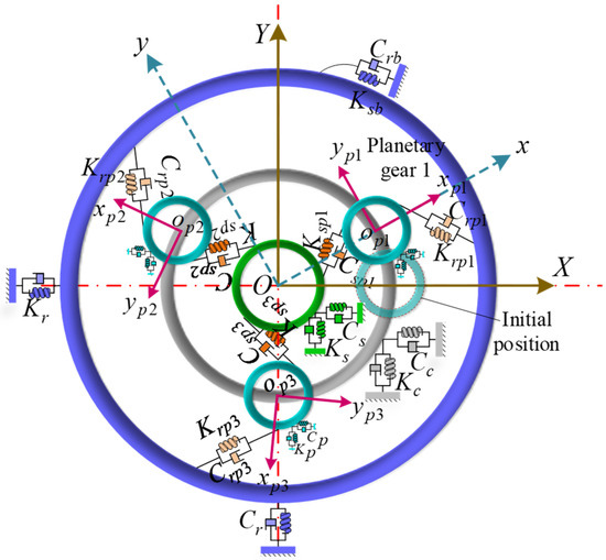
Figure 2.
The dynamic model of the gear transmission system.
In order to intuitively display the meshing relationship, the meshing dynamic model between the sun and planetary gear is shown in Figure 3a. Hypothetically, the direction of the sun gear output torque is clockwise. can be written using the following equation:
where denotes the position angle of the ith planetary gear. represents the transverse pressure angle. According to the geometric relationship, the projection of their meshing displacements along the meshing action line can be deduced as follows:
where and denote the meshing errors of the external meshing gear. and are the column vectors for the meshing element:
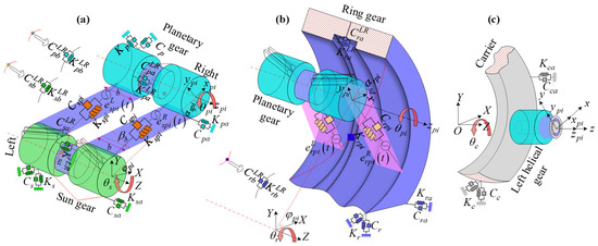
Figure 3.
Meshing dynamic model, (a) sun gear and planetary gears, (b) ring gear and planetary gears, (c) carrier and planetary gears.
The meshing vectors and can be written as:
where and stand for the radii of the pitch circle, which represents the sun and planetary gear. denotes the transverse pressure angle. is the base helix angle, and its expression is provided in the following equation:
where is the helix angle.
If the parameters of the left and right sides are the same, superscripts will be not used. Based on Newton’s second law, the motion differential equations of the sun gear can be expressed as the following equations:
where and . denote the meshing stiffness of the sun gear and planetary gear. represents their meshing damping. is the radial support stiffness of the sun gear. stands for the radial support damping of the sun gear. denotes its axial support stiffness. represents its axial support damping. denotes its torsional stiffness. represents its torsional damping. denotes the coupling axial support stiffness between the left-end helix gear and the right helix gear. represents their coupling axial support damping. denotes the coupling torsional stiffness between the left-end gear and the right gear. denotes their coupling torsional damping. is the equivalence displacement in the tangent direction of the corresponding base circle of the sun gear:
Relatively, the motion differential equations of the planetary gears can be expressed as the following:
where is the radius of the pitch circle of the carrier. is the mass of the planetary gear.
The dynamic equation of the extreme meshing can be rewritten as:
where represents the support and torsional damping matrix, denotes the support and torsional stiffness matrix. In addition, the mass matrix , meshing damping matrix , meshing stiffness matrix , vector of forces caused by the dynamic transmission errors , and the vector of external forces can be expressed as the following equations:
Figure 3b shows the dynamic model of the ring and planetary gear. Similarly, their motion equations can be established based on Newton’s second law, and it can be written as [12]:
Figure 3c shows the dynamic model of the carrier and planetary gear. In this section, L and R are not used because of the same parameters. The motion equations of the carrier and planetary gears can be deduced as follows:
where denotes the radial support stiffness of the carrier, represents the radial support damping of the carrier, denotes its axial support stiffness, and represents its axial support stiffness. is its mass.
According to Equations (13) and (14), the motion equations can be obtained as follows:
where represents the support damping matrix, denotes the support stiffness matrix. In addition, the mass matrix and vector of the external forces can be provided in the following equations:
The motion equations of all the subsystems were coupled into an overall motion equation, and it could be written as:
2.2.2. Meshing Stiffness
Based on the assumption of dynamic modelling that two helix gears are coupled into a herringbone gear, the meshing stiffness of the herringbone gear can be similarly calculated by coupling the meshing stiffness of the two helix gears, and its expression can be provided by the following equations:
where is the unilateral helical tooth width, represents the meshing stiffness per helical tooth width, and its calculation expression is:
where is the transverse contact ratio and stands for the flexibility of the unit tooth width, which is related to the tooth number and modification coefficient.
is the meshing damping ratio, and its value is in the range of 0.03 to 0.17. and are the radii of the base circles of the driving and driven gears. and are their masses.
2.2.3. Time-Varying Meshing Transmission Errors
The internal and external meshing errors, respectively, are shown as follows:
where denotes the meshing transmission error between the sun gear and planetary gear, represents their initial phase, denotes the meshing transmission error between the ring gear and planetary gear, represents their initial phase, is their meshing frequency, represents the tooth number of the sun gear, represents the tooth number of the ring gear, and is the meshing phase difference between the sun gear and ring gear. is the piecewise function, which is used to distinguish the meshing transmission error of the left and right helical gear. Its expression is provided in the following equation:
2.3. Wind Velocity Model
2.3.1. Turbulent Effect
The three-dimensional turbulent wind was simulated based on the Kaimal spectral model [31]:
where denotes the power spectral ensity (PSD), represents the friction velocity, , , , , and are six parameters of the wind spectral model, and stands for the reduced frequency. Its expression is as follows:
where denotes the mean wind velocity, represents the height in space, and is the frequency. In addition, the calculational expression of was simulated based on Weber’s research [32,33]:
According to Tieleman’s theory, the so-called blunt model and so-called pointed model are defined by four parameters, which are , , ; . , ; ; and for the blunt model, which can be used to describe topographic factor interference, whereas , is the pointed model, which is employed for describing flat topography. The Kaimal model is a mixed model because the horizontal wind is established using the blunt model, and the vertical wind is described using the pointed model. Thus, the calculation expression of the PSD from each component can be written as follows:
Except for the one-node wind simulation, a co-coherence function was used to describe the correlation of the turbulence from two nodes, for which the distance is . Its expression is defined as follows [34]:
where denotes the co-coherence and stands for the co-coherence exponential decay coefficient. Their values were set to:
Thus, the co-coherence power spectrum density matrix could be calculated via the following equation:
Then, the matrix was solved using the Cholesky decomposition method. Finally, the turbulent wind, u, v, w, could be obtained based on the Shinozika theory [35].
2.3.2. Wind Shear Effect
The wind shear effect is defined as the variation in the wind velocity and direction in a position in space. In the study of wind velocity, generally, the change in the wind velocity in the vertical direction is only considered. Based on the IEC standard [36], an exponential model was used to describe the wind shear effect:
where denotes the hub height, represents the wind velocity at the hub’s position, stands for the wind velocity of the height , and is the wind shear coefficient, normally.
Equation (30) can be also rewritten in the polar coordinate form:
where is the position angle of a node in the rotational plane of the impeller, is the distance between the centre of the impeller hub and this node, and is the wind shear coefficient. Its expression can be expanded using the third-order Taylor series [37]:
Clearly, the effect of the height on locational wind velocity is reflected in the size of , as shown in Figure 4.
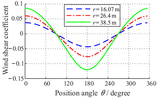
Figure 4.
Wind shear coefficient.
The mean wind velocity in the rotational plane of the impeller can be calculated using the following equation:
2.3.3. Tower Shadow Effect
Due to the hidden effect of the tower on the flow, the inflow velocity in the region of the tower’s upstream and downstream reduced. The phenomenon is defined as the tower shadow effect. In this wind turbine study, the tower shadow effect only occurred in the lower haft of the disk surface of the impeller. Thus, the tower shadow effect was expressed as the following equation:
where denotes the tower shadow coefficient and its expression can be provided using [38,39]:
where donates the tower’s radius, represents the shaft length between the impeller and hub. In general, the tower of large megawatt-scale wind turbines is designed to be wide at the bottom and narrow at the top. Thus, the tower’s radius changes with increasing height, and its expression is provided in the following equation:
where denotes the tower’s radius at , represents the radius of the tower bottom, and is the radius of the tower top. The tower shadow coefficient curves are shown in Figure 5.
Figure 5.
Tower shadow coefficient.
2.3.4. Wind Velocity
Based on the above theory and the sizes of the tower and blades, the sweep plane of the impeller was divided into 32 × 32 (1024) nodes to describe the turbulent wind velocity, as shown in Figure 6a,b. The horizontal coordinate represents the width of space and the vertical coordinate represents the height of space. The size parameters of the wind turbine are shown in Table 1. At 3 s, 6 s, and 9 s, the turbulent wind conditions are shown in Figure 7.
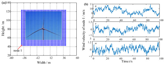
Figure 6.
Wind velocity description diagram, (a) divided wind farm nodes, and (b) the wind velocity of node 1.

Table 1.
Size parameters of the 1.5 MW wind turbine.
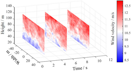
Figure 7.
Turbulent wind conditions at t = 3, 6, and 9 s.
2.4. Aerodynamic Load Calculation
The power of a wind turbine originates from the wind acting on the impeller. Meanwhile, it is also the main load on each component of the wind turbine. Thus, the accurate acquisition of aerodynamic forces on the blades is key to analyzing the loads. Currently, the methods for calculating the aerodynamic loads on the wind turbines are the traditional BEM, the Schmitz theory, and the generalized dynamic wake theory. Since the physical meaning of the BEM is clear and easy to understand, its modified model can be widely used in the wind turbine field. Therefore, the calculation of the aerodynamic load is solved using the BEM.
Before starting with the calculation of the aerodynamic load, the four coordinate systems were defined to display the blade element’s position as shown in Figure 8, and the construction of the coordinate systems could begin with the observation point P of the rotational wind blade 1. The coordinate system is connected to the ground and is a fixed system. The original point is set at the base of the tower. , , and represent the tower top position, hub position, and blade element position, respectively. Two inclination angles exist in the plane ( and ), but they are all set to zero for this calculated load task. The position angle, , between the three blades is 120 degrees. stands for the angular velocity of the impeller.
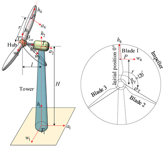
Figure 8.
Definition of the position coordinate of the blade element for the load calculation of the wind turbine.
According to the BEM, the lift and drag forces on each blade element are provided in:
where denotes the lift force unit, represents the drag force unit, is the airflow density, stands for the chord length on the interface where the blade element is located, and is the actual inflow wind velocity of the blade element; it can be obtained via the coordinate transformation of velocity under the turbulent wind condition. is the lift coefficient and is the drag coefficient.
The torque of the blade element can be written as:
To calculate the torques acting on the entire blade, it is only necessary to integrate the torque elements spanwise across the blade, as shown in Figure 9, Figure 10 and Figure 11. The inflow velocity of the hub is steady in the results from Figure 9 and Figure 10. The torque of the different blades can be seen in Figure 9a, and the torque variation is mainly affected by the wind shear effect. The torque presents periodic fluctuations. Combined with Figure 5, the value of is at its minimum when the blades rotate to 180 degrees. The blade alternating fluctuation is due to the position angle difference between the blades of 120 degrees.
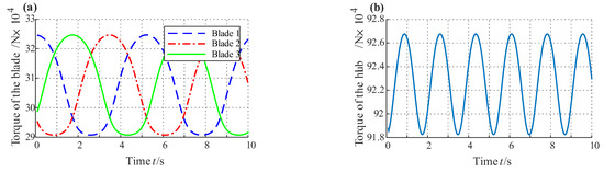
Figure 9.
Aerodynamic load with the wind shear effect of the different blades and hub at t = 10 s, (a) blades, and (b) hub.
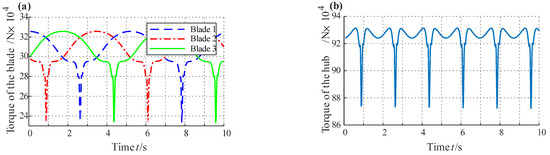
Figure 10.
Aerodynamic load with the wind shear and tower effect of the different blades and hub at t = 10 s, (a) blades, and (b) hub.
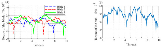
Figure 11.
Aerodynamic load with the wind shear, tower effect, and turbulence of the different blades and hub at t = 10 s, (a) blades, and (b) hub.
In addition, another key factor is the tower effect. After considering the combined wind shear and tower effect, the torque of the blades and hub is illustrated in Figure 10. The torque is weakened by this combined effect when the blades rotate to the centre area of the tower shadow, as can be seen in the marked position in Figure 10. This is because the actual wind velocity plunges under the combined effect when the blades’ position is 180 degrees, as shown in Figure 8. The torque drop not only has a huge impact on the transmission system but also has an obvious impact on the power grid. Through carefully comparing Figure 9a and Figure 10a, it can be found that the torque under the sole wind shear effect is smaller than the torque under the combined effect on both sides of the tower shadow centre area. This can make up for the power loss in the centre area of the tower shadow to a certain extent.
When the turbulence, wind shear, and tower effect are all considered, the torque presents a nonlinear fluctuation, as shown in Figure 11. The torque in the centre area of the tower shadow may be enhanced or not diminished because of the turbulent wind effect. Combined with the axial flow wind velocity map in Figure 7, the wind shear is still the main factor among the three. This is because the influence of the wind shear effect lasts, whereas the tower shadow effect works in a small area at its centre.
3. Results and Analysis
The parameters of the herringbone planetary gear of the wind turbine are shown in Table 2. Based on the modelling and theories, the hub loads could be precisely calculated under different wind conditions, as shown in Figure 9, Figure 10 and Figure 11. They can be seen as the external excitation acting on the carrier of this herringbone planetary gear system. Equation (17) can be solved using the Runge-Kutta method to obtain the displacements and velocities from each component in different directions. After that, the dynamics and load-sharing characteristics of this system could then be fully and clearly understood.
Table 2.
Wind turbine gearbox parameters [13].
3.1. Load-Sharing Characteristics
In order to quantify the load-balancing performance of the planetary transmission system, the load-balancing coefficient is defined here as [13]:
where and represent the time-varying load-sharing coefficient. stands for the meshing forces between the sun gear and planetary gear and stands for the meshing forces between the ring gear and planetary gear.
In order to evaluate the effect of the support stiffness on the load-sharing coefficient, the global load-sharing coefficient, SL, is present. Its expression can be written using [13]:
3.1.1. Effect of the Support Stiffness
In the section, the wind shear effect and the tower shadow effect are considered in the calculation of the hub load. Because the turbulent wind velocity has significant randomness, it was not considered. In addition, using periodic external excitation could more clearly describe the influence of the support stiffness on the load-sharing characteristics. The support stiffnesses of the main rotational components was set as the controlled parameters, and the damping was 0.2% of the stiffness based on the study of bearings in a wind turbine [40]. The load-sharing coefficient can be calculated using Equation (40). Value orthogonal tests of the sun gear support stiffness and planetary gear support stiffness are shown in Figure 12 and Figure 13. The value orthogonal tests of the ring gear support stiffness and planetary gear support stiffness are shown in Figure 14 and Figure 15.
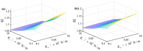
Figure 12.
Global load-sharing coefficient between the ring gear and planetary gear with the change in and , (a) left side, and (b) right side.
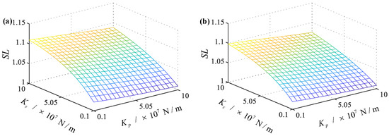
Figure 13.
Global load-sharing coefficient between the sun gear and planetary gear with the change in and , (a) left side, and (b) right side.
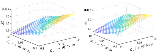
Figure 14.
Global load-sharing coefficient between the ring gear and planetary gear with the change in and , (a) left side, and (b) right side.
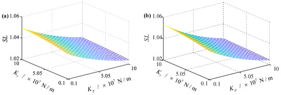
Figure 15.
Global load-sharing coefficient between the sun gear and planetary gear with the change in and , (a) left side, and (b) right side.
In summary, the value of can be seen in Figure 12a. It can be found that the coefficient decreases as the value of increases and increases as the value of increases. The minimum value of can be observed at the position corresponding to the coordinate . Moreover, as the value of the support stiffness increases, the variation degree of the load-sharing coefficient is different. When the is set to 106, the increase in is obvious with an increase in the value of , whereas this increasing trend is slight at . Similarly, when the is set to the minimum, the fluctuation decrease in the load-sharing coefficient is obvious with an increase in , whereas it exhibits a decline in the form of a parabolic function at . The variation trend of is shown in Figure 12b. Combined with Figure 12a, it can be seen that in the right-side model, the variation trend of the load-sharing coefficient is the same, but the magnitude of the number and the magnitude of the change are different. is smaller than . This is because the torsional coupling stiffness and damping of the left and right ends play a role.
The values of and can be seen in Figure 13a,b. It can be found that an obvious difference appears, as can be seen in Figure 13, with the variation in , whereas with an increase in , the decline in is slight.
The values of and with the change in and can be seen in Figure 14a,b. The global load-sharing coefficient and will decrease if increases. They will increase if increases. On the other hand, the effect of and on the global load-sharing coefficient is present. The values of and with the change of and can be seen in Figure 15a,b. It can be seen that opposite trends to Figure 14 are shown as the values of and change.
According to the above description and analysis, combined with Figure 12, Figure 13, Figure 14 and Figure 15, the support stiffness of the sun gear, , has a great influence on both the load-sharing coefficient between the ring and planetary gear and the load-sharing coefficient between the sun and planetary gear. The support stiffness of the ring gear, , only has an obvious effect on the load-sharing coefficient between the ring and planetary gear. Similarly, the support stiffness of the planetary gear, , is the same. Therefore, improving the support stiffness of the ring gear is the best scheme for the parameter adjustment. This scheme can not only reduce the load-sharing coefficient between the ring gear and planetary gear but also ensure that it does not have a significant impact on the load-sharing coefficient between the sun gear and planetary gear. Meanwhile, the support stiffness of the planetary gear should be designed to be a low value while ensuring that the design is reasonable. This can make the global load-sharing coefficient closer to 1 than before.
3.1.2. Contribution Rate Analysis
In order to analyze the effect of the different factors on the time-varying load-sharing characteristics, such as the turbulent, tower shadow effect, and wind shear effect, the relative contribution ratio and the real-time rate of change were proposed, and their expressions can be written as [41]:
where stands for the time-varying load-sharing coefficient without considering the i influence factor, denotes the time-varying load-sharing coefficient with all influence factors, and represents the time-varying load-sharing coefficient under the steady inflow condition ( = 11 m/s).
The relative contribution rate of each influence factor is shown in Figure 16 and Figure 17. The relative contribution rate of the turbulent was maintained at the highest level. Strikingly, the mean values of in Figure 16a,b and Figure 17a,b are 80.368%, 80.372%, 80.371%, and 80.370%, respectively. Regarding the tower shadow effect, they are 10.314%, 10.312%, 10.312%, and 10.313%. The contribution rate of the wind shear effect were calculated to be 9.318%, 9.316%, 9.317%, and 9.317%. These can describe the whole variation of the relative contribution rate. However, the time-varying properties cannot be reflected.
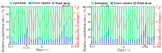
Figure 16.
Analysis of the proportion of each influencing factor on the time-vary load-sharing coefficient between the ring gear and planetary gear 1 (), (a) left side, and (b) right side.
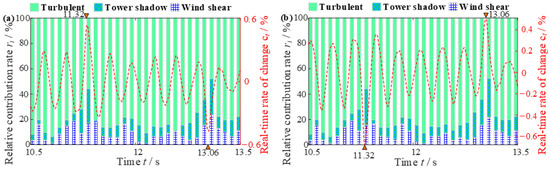
Figure 17.
Analysis of the proportion of each influencing factor on the time-vary load-sharing coefficient between the ring gear and planetary gear 1 (), (a) left side, and (b) right side.
In Figure 16a, the relative contribution rate ranges of the wind shear, tower shadow, and turbulent are [0.91%, 23.61%], [1.31%, 28.44%], and [47.94%, 93.88%]. It is not difficult to find the law of the contribution rates of the wind shear and tower shadow. The excitation load enters the shadow effect center at t = 11.32 s and t = 13.06 s. When the load excitation enters the region of the tower shadow, their values increase gradually, whereas the load excitation exits the region of the tower shadow, and their values decrease. In particular, the contribution rate of the tower shadow quickly climbed to 28.44%. This is because the tower shadow causes the load excitation to quickly fall. When the blades are not in the region of the tower shadow, the contribution rate of the wind shear and tower is low (mean ≤ 7%). This means that the effect of the wind shear and tower shadow can be ignored at this stage.
In addition, combined with Figure 16 and Figure 17, the real-time rate of change in is smaller than . It shows that the load-sharing characteristic between the ring gear and planetary gear is more sensitive to turbulent wind conditions than between the sun gear and planetary gear. This also reminds designers to focus on the design of the gear rings. The cyclic aerodynamic load caused by the wind shear and tower shadow effect always exists, and when the excitation enters the tower shadow region, the wind shear and tower shadow effect will affect the load-sharing characteristics of the system. The vibration and fatigue problems of the wind turbine gearboxes become more complicated. At the same time, due to the periodic change in the load, the output power of the grid-connected wind turbines also has certain fluctuations, and the output power quality will be affected to a certain extent.
3.2. Dynamic Characteristics
To analyze the dynamic characteristics in the herringbone planetary gear system, the different wind conditions, including the steady inflow (VH = 11 m/s) and turbulent wind, were considered in the motion equations. After solving, the meshing forces, displacements, and centroid trajectories could be obtained. Their description and analysis are shown as follows. In addition, the turbulent wind in this section stands for a wind condition including the wind shear, tower shadow, and turbulent effect.
3.2.1. Meshing Force
In Figure 18 and Figure 19, the internal and external meshing forces are displayed, respectively. It can be seen that the meshing forces acting on the internal meshing line are slightly affected by the turbulent wind condition, and the right side is larger than the left side. This is because the space translational displacement of the right side from the ring gear is larger than the left side, as can be seen in Figure 20 and Figure 21. Only after the blade enters the centre of the tower shadow effect, the meshing force curve will have an obvious impact. In addition, the meshing forces curves under turbulent wind conditions are lower than the meshing forces under steady inflow. This is mainly due to the decline in the wind velocity caused by the wind shear.
Figure 18.
Analysis of the meshing forces between the ring gear and planetary gear 1, (a) left side, and (b) right side.
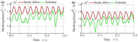
Figure 19.
Analysis of the meshing forces between the sun gear and planetary gear 1, (a) left side, and (b) right side.
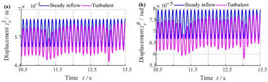
Figure 20.
Analysis of the axial displacement from the ring gear, (a) left side, (b) and right side.
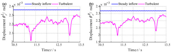
Figure 21.
Analysis of the torsional displacement from the ring gear, (a) left side, and (b) right side.
In Figure 19, except for the above analysis, the meshing forces acting on the external meshing line are larger than those acting on the internal meshing line. They are strongly affected by the turbulent wind conditions. This is because the torsional displacement fluctuation is large from the sun gear. Notably, the meshing frequency of the sun gear is higher than the other. If the force on the tooth surface is also high, tooth surface damage is unavoidable. Therefore, the gear pair between the sun gear and planetary gear should be handled specifically in manufacturing and design to decrease the meshing stiffness. In the design of the herringbone gearbox, the external meshing gear pair should be specially treated to deal with the problem of meshing impact enhancement under dynamic loads.
3.2.2. Displacement
As can be seen in Figure 20 and Figure 21, the torsional displacements of the ring gear are more obviously influenced by the turbulent wind condition than the axial displacements. This is because the axial excitation is ignored after considering the herringbone gear special structure and the bearing support design of this wind turbine. Therefore, the fluctuations in the axial displacements are generated by the axial–torsion coupling term in the motion equations. This greatly weakens the influence of the turbulent wind condition on the axial vibration in the transmission system. Meanwhile, this means that the axial displacements of the ring gear are slightly affected by the torsional excitation under turbulent wind conditions. In the design of the ring gear, the fluctuation in the torsional excitation can be ignored.
The axial and torsional displacements of the sun gear are shown in Figure 22 and Figure 23. Similarly, the torsional displacement variation trends of the sun gear are the same as the ring, but these are larger than the ring gear. This is because the rotational velocity is larger, the torque is smaller, and the vibration is larger.
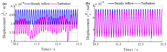
Figure 22.
Analysis of the axial displacement from the sun gear, (a) left side, (b) and right side.
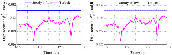
Figure 23.
Analysis of the torsional displacement from the sun gear, (a) left side, and (b) right side.
In summary, the vibration amplitude of the sun gear in the torsional direction should be concerned. However, both the ring gear and sun gear are sensitive to turbulent wind conditions but the vibration amplitudes of the ring gear are small, whereas, from the sun gear, it is too large. In this way, the sun gear is subjected to both high-frequency loads and low-frequency loads.
4. Discussion
In Section 3, the contribution rate from the different influence factors on the load-sharing coefficient is discussed using statistical methods. It can be found that the most sensitive factor that causes changes in the load-sharing characteristics is the turbulent effect through the time-varying relative contribution rate and rate of change. The contribution rates of the tower shadow and wind shear effect also surge when the blades enter the centre region of the tower shadow. This causes serious fluctuations in the time-varying load-sharing coefficient. This is because the superposition of the two effects makes the external excitation load fluctuate greatly.
The wind shear effect is mainly affected by the ground roughness. Based on the measured data, the mean wind shear coefficient of the sea, plain, hill, mountainous area, and seaside are approximately 0.1, 0.14, 0.17, 0.22, and 0.32, respectively. But these are just the estimates related to ground roughness. For example, the terrain is mostly hilly and plain in the central and eastern parts of China, but the measured wind shear coefficient is above 0.3. Based on the above different terrain, the influence of the wind shear effect on the global load-sharing coefficient is shown in Table 3 through the method of this paper. The wind shear effect is only considered.
Table 3.
Effect of the wind shear coefficient.
Flat terrain can improve the load-sharing characteristics, but the improvement is slight. However, the turbulence intensity is different in different terrains, and turbulence is the main cause of uneven load based on above the study.
In addition, the tower shadow coefficient is mainly affected by the tower size. The load-sharing characteristics of the transmission system can be improved by reducing the impact caused by the tower shadow effect. Meanwhile, the theoretical numerical results are provided in Table 4.
Table 4.
Effect of the tower shadow.
Through the table, it can be seen that the tapered tower design can effectively improve the load-sharing characteristics of the transmission system. Three influence factors were considered in this paper, but realistic wind conditions are complex and there are many more factors than were considered in this paper, such as the wake effect, stall effect, voltage drop, extreme wind regime, and so on. If their contribution rates are analyzed, the research mode in this paper can provide a reference. The precise modelling of environmental loads and transmission systems is still the direction of our future research.
5. Conclusions
In this study, the load-sharing and dynamic characteristics of a herringbone planetary gear transmission system in a wind turbine were researched using the simulation method. The main conclusions are as follows:
- (1)
- The load-sharing coefficients of the left and right sides are similarly sensitive to the support stiffness, and the difference between the two is small. The support stiffness of the planetary gear can alter the effect of the support stiffness of the ring gear and sun gear on the load-sharing coefficient and vice versa. The interaction between the three stiffnesses should be considered when adjusting the support stiffness to control the load-sharing characteristics;
- (2)
- The turbulent effect is the most critical cause of the time-varying load-sharing characteristic variation, followed by the wind shear effect and tower shadow effect. Although when the blades enter the centre region of the tower shadow, the influence of the wind shear effect and tower shadow effect increased; they still do not exceed the turbulent effect;
- (3)
- The meshing forces acting on the external meshing line are obviously greater than those acting on the internal meshing line under turbulent wind conditions. In the design of the herringbone gearbox, the external meshing gear pair should be specially treated to deal with the problem of meshing impact enhancement under dynamic loads.
As a whole, the present work investigated the dynamic characteristics of a herringbone planetary gear system applied to a wind turbine under turbulent wind conditions. The study demonstrates that accurately calculating the torque load of the wind turbine gearbox is necessary because the dynamic behavior of the inner and outer meshing pairs is different after the action of a time-varying load. Additionally, the left and right sides of the herringbone gear are not the same. This provides an effective theoretical reference for the design of the herringbone planetary gear of wind turbines. Through the analysis and discussion, the correct geographical position of the wind turbine and the reasonable design of the tower are both good schemes that can effectively ensure the load-sharing performance of the transmission system and reduce the vibration. Further studies on the optimal design of the herringbone planetary gearbox of a wind turbine will be conducted to achieve the purpose of reducing vibration and extending service life.
Author Contributions
Conceptualization, W.-q.Z.; formal analysis, W.-q.Z., W.Z. and J.L.; funding acquisition, W.Z.; investigation, W.-q.Z.; methodology, W.-q.Z.; project administration, W.-q.Z.; resources, J.L. and W.Z.; supervision, J.L.; validation, W.-q.Z. and N.Y.; visualization, N.Y.; writing—original draft, W.-q.Z.; writing—review and editing, W.Z., J.L. and N.Y. All authors have read and agreed to the published version of the manuscript.
Funding
This work is supported by the Strategic Pilot Science and Technology Project of Chinese Academy of Sciences (Grant no. XDC04030503).
Data Availability Statements
The datasets generated by the study can be obtained from the corresponding authors upon reasonable request. The specific parameters of the study can be found in the tables in the paper.
Conflicts of Interest
The authors declare that there are no potential conflicts of interest in this paper.
References
- Kahraman, A. Load sharing characteristics of planetary transmissions. Mech. Mach. Theory 1994, 29, 1151–1165. [Google Scholar] [CrossRef]
- Kahraman, A.; Vijayakar, S. Effect of internal gear flexibility on the quasi-static behavior of a planetary gear set. J. Mech. Des. 2001, 123, 408–415. [Google Scholar] [CrossRef]
- Yang, J.; Dai, L. Survey of dynamics of planetary gear trains. Int. J. Mater. Struct. Integr. 2008, 1, 302–322. [Google Scholar] [CrossRef]
- Crowther, A.R.; Singh, R.; Zhang, N.; Chapman, C. Impulsive response of an automatic transmission system with multiple clearances: Formulation, simulation and experiment. J. Sound. Vib. 2007, 306, 444–466. [Google Scholar] [CrossRef]
- Ligata, H.; Kahraman, A.; Singh, A. An experimental study of the influence of manufacturing errors on the planetary gear stresses and planet load sharing. J. Mech. Des. 2008, 130, 041701. [Google Scholar] [CrossRef]
- Guo, Y.; Keller, J.; Parker, R.G. Nonlinear dynamics and stability of wind turbine planetary gear sets under gravity effects. Eur. J. Mech. A Solid 2014, 47, 45–57. [Google Scholar] [CrossRef]
- Zhao, W.Q.; Liu, J.; Zhao, W.H.; Zheng, Y. An investigation on vibration features of a gear-bearing system involved pitting faults considering effect of eccentricity and friction. Eng. Fail. Anal. 2022, 131, 105837. [Google Scholar] [CrossRef]
- Xiang, L.; An, C.; Hu, A. Nonlinear dynamic characteristics of wind turbine gear system caused by tooth crack fault. Int. J. Bifurc. Chaos 2021, 31, 2150148. [Google Scholar] [CrossRef]
- Zhang, X.; Zhong, J.; Li, W.; Bocian, M. Nonlinear dynamic analysis of high-speed gear pair with wear fault and tooth contact temperature for a wind turbine gearbox. Mech. Mach. Theory 2022, 173, 104840. [Google Scholar] [CrossRef]
- Zhao, Y.; Ahmat, M.; Bari, K. Nonlinear dynamics modeling and analysis of transmission error of wind turbine planetary gear system. Proc. Inst. Mech. Eng. Part K J. Multi-Body Dyn. 2014, 228, 438–448. [Google Scholar] [CrossRef]
- Mo, S.; Zhang, T.; Jin, G.-G.; Cao, X.-L.; Gao, H.-J. Analytical investigation on load sharing characteristics of herringbone planetary gear train with flexible support and floating sun gear. Mech. Mach. Theory 2020, 144, 103670. [Google Scholar]
- Mo, S.; Zhang, T.; Jin, G.G.; Feng, Z.Y.; Gong, J.B.; Zhu, S.P. Influence mechanism of multi-coupling error on the load sharing characteristics of herring-bone gear planetary transmission system. Proc. Inst. Mech. Eng. Part K J. Multi Body Dyn. 2019, 233, 792–816. [Google Scholar]
- Mo, S.; Zhang, T.; Jin, G.G.; Feng, Z.Y.; Gong, J.B.; Zhu, S.P. Dynamic characteristics and load sharing of herringbone wind power gearbox. Math. Probl. Eng. 2018, 2018, 7251645. [Google Scholar] [CrossRef]
- Wang, C.L.; Wei, J.; Wu, Z.H.; Lu, L.; Gao, H. Load sharing performance of herringbone planetary gear system with flexible pin. Int. J. Precis. Eng. Manuf. 2019, 20, 2155–2169. [Google Scholar] [CrossRef]
- Hou, S.; Wei, J.; Zhang, A.; Lim, T.C.; Zhang, C. Study of dynamic model of helical/herringbone planetary gear system with friction excita-tion. J. Comput. Nonlinear Dyn. 2018, 13, 121007. [Google Scholar] [CrossRef]
- Wang, S.; Zhu, R. Research on dynamics and failure mechanism of herringbone planetary gearbox in wind turbine under gear surface pitting. Eng. Fail. Anal. 2023, 146, 107130. [Google Scholar] [CrossRef]
- Xu, X.; Ge, H.; Wu, H. Research on nonlinear characteristics of herringbone planetary gear transmission system con-sidering double-sided meshing impact. Nonlinear Dyn. 2024, 112, 3195–3215. [Google Scholar] [CrossRef]
- Wang, C. Three-dimensional modification for vibration reduction and uniform load distribution focused on unique transmission characteristics of herringbone gear pairs. Mech. Syst. Signal Process. 2024, 210, 111153. [Google Scholar] [CrossRef]
- Wu, L.; Feng, W.; Yang, L.; Yang, H.; Yang, S.; Liu, B. Dynamic modeling and vibration analysis of herringbone gear system with uncertain parameters. Arch. Appl. Mech. 2024, 94, 221–237. [Google Scholar] [CrossRef]
- Chen, R.; Qin, D.; Yi, Y.; Liu, C.; Shi, J. Dynamic characteristics of electromechanical coupling of wind turbine drive system under multi-source excitation. Wind Energy 2022, 25, 391–418. [Google Scholar] [CrossRef]
- Wang, S.; Nejad, A.; Bachynski, E.E.; Moan, T. A comparative study on the dynamic behaviour of 10 MW conventional and com-pact gearboxes for offshore wind turbines. Wind Energy 2021, 24, 770–789. [Google Scholar] [CrossRef]
- Tan, J.; Zhu, C.; Song, C.; Xu, X.; Wang, Z. Investigation of dynamic characteristics of planetary gear stage in wind turbine considering voltage dip. J. Mech. Sci. Technol. 2019, 33, 4139–4154. [Google Scholar] [CrossRef]
- Tan, J.; Zhu, C.; Song, C.; Li, Y.; Xu, X. Dynamic modeling and analysis of wind turbine drivetrain considering platform motion. Mech. Mach. Theory 2019, 140, 781–808. [Google Scholar] [CrossRef]
- Abo-Khalil, A.G.; Alyami, S.; Sayed, K.; Alhejji, A. Dynamic modeling of wind turbines based on estimated wind speed under turbulent conditions. Energies 2019, 12, 1907. [Google Scholar] [CrossRef]
- Wang, S.; Moan, T.; Jiang, Z. Influence of variability and uncertainty of wind and waves on fatigue damage of a floating wind turbine drivetrain. Renew. Energy 2022, 181, 870–897. [Google Scholar] [CrossRef]
- Porté-Agel, F.; Bastankhah, M.; Shamsoddin, S. Wind-turbine and wind-farm flows: A review. Bound. Layer Meteorol. 2020, 174, 1–59. [Google Scholar] [CrossRef] [PubMed]
- Doagou-Rad, S.; Mishnaevsky, L., Jr.; Bech, J.I. Leading edge erosion of wind turbine blades: Multiaxial critical plane fatigue model of coating degradation under random liquid impacts. Wind Energy 2020, 23, 1752–1766. [Google Scholar] [CrossRef]
- Da Silva, L.S.P.; de Oliveira, M.; Cazzolato, B.; Sergiienko, N.; Amaral, G.; Ding, B. Statistical linearisation of a nonlinear floating offshore wind turbine under random waves and winds. Ocean Eng. 2022, 261, 112033. [Google Scholar] [CrossRef]
- Bangga, G.; Lutz, T. Aerodynamic modeling of wind turbine loads exposed to turbulent inflow and validation with experi-mental data. Energy 2021, 223, 120076. [Google Scholar] [CrossRef]
- Bangga, G.; Dessoky, A.; Wu, Z.; Rogowski, K.; Hansen, M.O.L. Accuracy and consistency of CFD and engineering models for simulating vertical axis wind turbine loads. Energy 2020, 206, 118087. [Google Scholar] [CrossRef]
- Kaimal, J.C.; Wyngaard, J.C.J.; Izumi, Y.; Coté, O.R. Spectral characteristics of surface-layer turbulence. Q. J. R. Meteorol. Soc. 1972, 98, 563–589. [Google Scholar]
- Weber, R.O. Remarks on the definition and estimation of friction velocity. Bound. Layer Meteorol. 1999, 93, 197–209. [Google Scholar] [CrossRef]
- Cheynet, E.; Jakobsen, J.B.; Obhrai, C. Spectral characteristics of surface-layer turbulence in the North Sea. Energy Procedia 2017, 137, 414–427. [Google Scholar] [CrossRef]
- Wang, J.; Cheynet, E.; Snæbjörnsson, J.Þ.; Jakobsen, J.B. Coupled aerodynamic and hydrodynamic response of a long span bridge suspended from floating towers. J. Wind. Eng. Ind. Aerodyn. 2018, 177, 19–31. [Google Scholar] [CrossRef]
- Shinozuka, M.; Deodatis, G. Simulation of stochastic processes by spectral representation. Appl. Mech. Rev. 1991, 44, 191–204. [Google Scholar] [CrossRef]
- IEC 61400-1-Ed. 3.0; Wind Turbines-Part 1: Design Requirements. International Electrotechnical Commission: Geneva, Switzerland, 2005.
- Wen, B.; Wei, S.; Wei, K. Influence of wind shear and tower shadow on the power output of wind tubine. J. Mech. Eng. 2018, 54, 124–132. [Google Scholar] [CrossRef]
- Sørensen, P.; Hansen, A.D.; Rosas, P.A.C. Wind models for simulation of power fluctuations from wind farms. J. Wind Eng. Ind. Aerodyn. 2002, 90, 1381–1402. [Google Scholar] [CrossRef]
- Gasch, R.; Jochen, T. Wind Power Plants: Fundamentals, Design, Construction and Operation; Springer. Science & Business Media: Berlin/Heidelberg, Germany, 2011. [Google Scholar]
- Vanhollebeke, F.; Peeters, P.; Helsen, J.; Lorenze, E.D.; Manzato, S.; Peeters, J.; Vandepitte, D.; Desmet, W. Large scale validation of a flexible multibody wind turbine gearbox model. J. Comput. Nonlinear Dynam. 2015, 10, 041006. [Google Scholar] [CrossRef]
- Zhang, A.; Wei, J.; Shi, L.; Qin, D.; Lim, T.C. Modeling and dynamic response of parallel shaft gear transmission in non-inertial system. Nonlinear Dynam. 2019, 98, 997–1017. [Google Scholar] [CrossRef]
Disclaimer/Publisher’s Note: The statements, opinions and data contained in all publications are solely those of the individual author(s) and contributor(s) and not of MDPI and/or the editor(s). MDPI and/or the editor(s) disclaim responsibility for any injury to people or property resulting from any ideas, methods, instructions or products referred to in the content. |
© 2024 by the authors. Licensee MDPI, Basel, Switzerland. This article is an open access article distributed under the terms and conditions of the Creative Commons Attribution (CC BY) license (https://creativecommons.org/licenses/by/4.0/).