Abstract
Torque vectoring is a widely known technique to improve vehicle handling and to increase stability in limit conditions. With the advent of electric vehicles, this is becoming a key topic since it is possible to have distributed powertrains, i.e., multiple motors are adopted, in which each motor is controlled separately from the others. Moreover, electric motors deliver the torque required by the controller faster and more precisely than internal combustion engines, active differentials and conventional hydraulic brakes. The state of the art of Direct Yaw Moment Control (DYC) techniques, ranging from classical to modern control theories, are analyzed and discussed in this paper. The aim is to give an overview of the currently available approaches while identifying their drawbacks regarding performances and robustness when dealing with common issues like model uncertainties, external disturbances, friction limit and common state estimation problems. This contribution analyzes all the steps from the lateral dynamics reference generation to the desired control action computation and allocation to the available actuators. In addition, some of the presented control logic is evaluated in a simulation environment for a passenger car. Results of both open-loop and closed-loop maneuvers allow the comparison and clarification of each control strategy’s key advantages.
1. Introduction
In recent years, Electric Vehicles (EVs) have become an increasingly popular alternative to conventional internal combustion engine vehicles []. To both governments and the mass public, they appear as a solution for reducing air pollution and its consequences on human health [].
In this context, the powertrain has been redesigned to exploit all the features offered by electric motors []. In fact, more than one motor can be fitted in the vehicle. Among distributed motor powertrains, a common approach is that of In-Wheel Motors (IWMs), which allows for effective packaging and high efficiency []. Moreover, using distributed motors allows significant improvements from the vehicle dynamics point of view. The possibility of independently controlling the torque on each wheel quickly and precisely makes applying Torque Vectoring Control (TVC) strategies easy. Indeed, Torque Vectoring (TV) consists in applying different longitudinal forces to the wheels of the same axle, resulting in a yaw moment that is used to control the vehicle lateral dynamics. Different powertrain layouts have been compared in the literature [,,,], and it is generally agreed that the best performing one is that with a four independent wheel drive system. Moreover, in certain cases, TV control is also combined with Active Front Steering (AFS) [], Active Rear Steering (ARS) [] and Four-Wheel Steering (4WS) [,].
This paper presents a review of torque vectoring control systems. Conversely to other vehicle chassis control reviews already present in the literature [,,,,], this paper focuses on torque vectoring, providing an overview of the available techniques and including a comparison of simulation results to highlight advantages and disadvantages of the most relevant strategies. Furthermore, this contribution analyzes all three levels of the cascaded control, reporting the different approaches used in the literature.
TV potential in enhancing vehicle handling is so significant [,] that these control strategies were adopted before the advent of electric motors. At that time, TV was either actuated through active and semi-active differentials [,,,,,] or through individually controlled wheel brakes [,,,,,], as it is still used nowadays in some applications [,]. Nevertheless, both actuation systems are less effective than electric motors because of slower dynamics, lower efficiency and flexibility, while also showing an increased integration complexity.
Regarding TV control architecture, most of the literature proposes a multilayer cascaded control composed by three main blocks, as in Figure 1, which include the following:
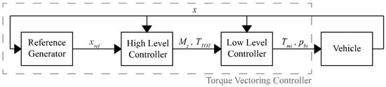
Figure 1.
Torque vectoring control scheme.
- reference generator;
- high-level controller;
- low-level controller.
The three components of the TV controller are briefly introduced hereafter, while a more in-depth description is given in the following sections, with the main focus being the high-level controller.
The reference generator obtains the driver inputs and the vehicle states () to generate a reference () for yaw rate and/or sideslip angle, which are the relevant quantities related to vehicle lateral dynamics. Most of the times, the reference quantity for vehicle-handling improvement is the yaw rate. In the most straightforward approach, based on the tuning of the understeer gradient, the reference yaw rate is a linear function of the driver steering angle input [,,,,,,,,]. An evolution of this approach accounts for a variable desired understeer gradient [], that is selected based on driver intention recognition when entering or exiting a curve. Nevertheless, this approach does not account for the non-linear dynamics characterizing the vehicle at high acceleration levels. For this reason, the authors in [] proposed a correction factor based on a feedforward neural network adopting the steering angle and the vehicle speed as inputs. Later, a more advanced approach was proposed in [] and adopted by many other authors in a slightly modified formulation [,,,,,,,] where the idea is to fully design the understeer characteristics of the vehicle with any shape not limited to the linear behavior. Using this approach, different vehicle behaviors can be obtained, corresponding to different understeer characteristics, being denoted as the driving modes [,]. Driving modes are sometimes selectable by drivers to adjust the vehicle behavior to their actual desires, such as a sport mode that improves the fun-to-drive experience. Driving modes can be designed to target not only vehicle handling performances but also energy efficiency requirements. In fact, some works have as their primary target the energetic efficiency of the vehicle, which is achieved by a proper design of the vehicle’s understeer characteristics [,].
The vehicle sideslip angle is often considered along with the yaw rate as a reference quantity since it provides an indication about vehicle lateral stability. It must be pointed out that, in general, controlling the yaw rate and sideslip angle simultaneously can be a challenging task since the two requirements are often conflicting. In general, two approaches can be found for the integration of sideslip angle control, which are:
- the sideslip angle reference is an additional control objective independent from the yaw rate reference [,], scheduling the control action based on driving conditions to manage conflicting requirements, e.g., sideslip angle contribution is only introduced when it exceeds a threshold value [,];
- the yaw rate reference is modified based on the sideslip angle value to increase vehicle stability [,].
The high-level controller takes as input the driver commands, the vehicle states and the output quantities from the reference generator. These inputs then define the total driving torque () and yaw moment () to be applied to the vehicle. Two parallel logics generally compute the two outputs of the high-level controller. The total torque demand is obtained through a drivability controller, while the yaw moment is obtained through the torque vectoring controller. The drivability controller uses drivability maps to define the amount of total driving torque to be delivered to the wheels to fulfill the driver demands, i.e., the accelerator pedal position is converted into a total torque reference for the engine or the motors. Instead, the torque vectoring controller computes the total desired yaw moment to be applied to the vehicle according to various approaches. The simplest method consists in a Proportional–Integral–Derivative (PID) controller [,,] based on the error between the reference and the actual value of the yaw rate and/or sideslip angle. Alternatively, optimal controllers can be used to track state references [,]. This approach generally requires a reliable vehicle model, which allows it to outperform the simple PID approach. Conversely to optimal approaches, it is possible to mention Sliding Mode Control (SMC) [,] or also fuzzy logic control [,]. Through the years, Model Predictive Control (MPC) [,] has also become widespread thanks to the improved computational capabilities of micro-processors. As in other fields, the last trend in vehicle dynamics yaw control also concerns the adoption of Reinforcement Learning (RL) techniques [,].
The low-level controller takes the total driving torque and yaw moment demand as inputs. Then, it generates a torque demand for each motor () and, if necessary, a braking pressure for each brake caliper (). This level is necessary because, in over-actuated vehicles, the high-level requests are not met in a straightforward manner, but it is necessary to properly allocate the single actuator efforts to meet the virtual high-level requests []. In torque vectoring studies, the low-level torque distributor is designed in two alternative ways. The first considers a front-to-rear distribution, which the designer fixes a priori, while the second considers an optimal torque allocation to wheels. The optimal approach deals alternatively with the equal exploitation of tire adherence or the energy efficiency of the whole vehicle. In some cases, where the target is energy efficiency, the high-level and the low-level controllers are designed together. In this way, the required yaw moment is also computed to save energy while giving less importance to the vehicle handling performance.
This paper is organized as follows: First, different torque vectoring control approaches are presented. Then, the simulation models are defined. Finally, the simulation results of relevant TVC strategies are reported.
2. Torque Vectoring Control
This section presents in detail the three main components that constitute torque vectoring controllers, making reference to the approaches employed in a wide range of the literature. To focus on the control strategy, all vehicle states are assumed to be available to the controller, and the state estimation issue is not addressed in this paper. This assumption is significant since, in the context of passenger vehicles, crucial quantities like vehicle sideslip angle or tire–road contact forces and friction coefficient are not directly measurable but require estimation. A comprehensive overview of techniques and approaches for tire and vehicle state estimation can be found in [,,,], where an exhaustive literature review is provided.
2.1. Reference Generator
The reference generator aims to define the desired vehicle lateral dynamics behavior, thereby generating references for the controller. When dealing with vehicle lateral dynamics, the most common approach considers yaw rate and sideslip angle responses, which are the two state variables representative of cornering performance and stability. Two approaches are commonly employed for defining the reference yaw rate. The first establishes a linear relationship between the yaw rate and the input steering angle, while the second defines a piecewise function linking the yaw rate to the input steering angle.
The simplest method for determining reference values for yaw rate and sideslip angle involves the linearization of the steady-state equations of motion of a single-track vehicle model [,,,,,,,,,,,,]. This approach results in the reference yaw rate being expressed as a linear function of the input steering angle and thus reads:
where is the reference yaw rate; the vehicle speed; the vehicle wheelbase; the understeering coefficient and the wheels steering angle. The understeering coefficient is, in turn, a function of vehicle and tire properties and is defined as follows:
where represents the vehicle mass, and denote the distances between the vehicle center of mass and the front and rear axle, respectively, and and are the cornering stiffnesses of the front and rear axle, respectively. This approach enables the manipulation of the vehicle’s cornering response by acting on the understeering coefficient (). However, the linear nature of this approach for the reference yaw rate has limitations due to the inherent linearization and is thus effective within the linear region of tires (typically below 4 m/s2 lateral acceleration). Notably, this method does not account for tire–road friction, which physically restricts the maximum attainable yaw rate. To address this limitation, a more sophisticated approach is introduced, allowing for a detailed design of the reference understeer characteristic [,,,,,,,,,,,,,,]. In relation to that, a piecewise function defines the relationship between the dynamic steering angle and the lateral acceleration , which, under quasi-steady-state conditions, is directly associated with the reference yaw rate (). This approach originates from defining the steering angle as the sum of dynamic and kinematic components, with the latter obtained from the Ackermann formula, as in the following:
where represents the curvature radius of the vehicle trajectory. Then, the piecewise function defining the relationship between the dynamic steering angle and the lateral acceleration retains a linear trait defined as in the previous approach. However, it introduces an upper limit associated with the maximum lateral acceleration, constrained by the available tire–road friction. To avoid any discontinuity, the two linear traits are interconnected using an exponential function, yielding the following set of expressions:
where is the understeer gradient, denotes the lateral acceleration at the limit of the linear region of the understeering characteristic and represents the maximum lateral acceleration achievable with the available tire–road friction. These three parameters hold a clear physical meaning, and tuning them allows the accomplishment of three design objectives for the vehicle understeer characteristic, as illustrated in Figure 2:
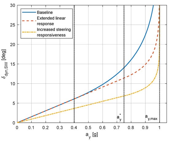
Figure 2.
TV control objectives.
- reduction in the understeer gradient kU compared with the baseline vehicle, leading to increased steering responsiveness, which is characteristic of a vehicle closer to neutral behavior;
- extension of the linear cornering response region by increasing the lateral acceleration limit for the transition between the linear trait and the saturation region;
- increase in the maximum achievable lateral acceleration , maximizing the utilization of available tire–road friction. This objective is feasible because the maximum lateral acceleration occurs when the vehicle experiences a yaw moment, as detailed in the Milliken Moment Method (MMM) diagrams in [].
It is worth mentioning that the cornering responses depicted in Figure 2 do not represent the response of an actual vehicle, but they serve for elucidating potential enhancements in the steady-state vehicle cornering response. These improvements are typically attainable through a proper vehicle setup or by incorporating an active vehicle lateral dynamics control and setting the desired vehicle cornering response as the reference quantity to be tracked. As the reference cornering response is derived under steady-state conditions, precise tracking is crucial in quasi-steady-state conditions. Conversely, when addressing transient conditions, the same reference can be adopted to mitigate the undesired variability in the vehicle’s cornering response even though the tracking results less precise.
Translating the control reference in terms of lateral acceleration into the equivalent yaw rate reference is straightforward, as the two quantities are linked by a precise relationship in steady-state conditions. This implies that the maximum attainable yaw rate is the maximum achievable lateral acceleration normalized by the actual vehicle speed (). Designating as the yaw rate value at which the transition between the linear and saturation regions occurs, and knowing that this phenomenon happens at a steering angle , the yaw rate reference can be expressed as:
where all the mentioned quantities are already known. When following the presented approach, it is crucial to consider that the maximum vehicle acceleration is constrained by the available tire–road friction. Consequently, a longitudinal acceleration results in a reduction in the maximum attainable lateral acceleration. Thus, the yaw rate reference () can be derived as the function of steering wheel angle input (), vehicle speed () and longitudinal acceleration (), as illustrated in Figure 3.
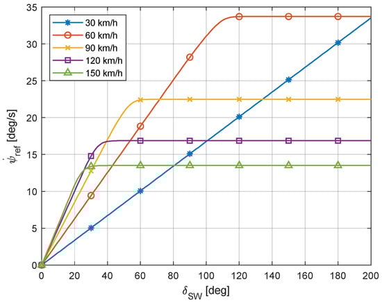
Figure 3.
Reference yaw rate at different running speeds for null longitudinal acceleration.
In some cases, a combined control on yaw rate and sideslip angle is proposed, as a lower sideslip angle corresponds to improved vehicle drivability. The simplest approach for defining the reference sideslip angle is still based on the linearization of the steady-state equations of motion of a single-track vehicle model [,,,,,,]. This approach allows for the definition of the reference sideslip angle () as a function of the reference yaw rate, leading to either a linear or a saturating expression depending on the definition of the reference yaw rate.
Another widely used approach to limit the sideslip angle value, with the aim of ensuring vehicle stability, is to impose a null reference value [,,,]. This usually requires an extremely high control effort, and thus, a more relaxed formulation has been proposed in the literature. This defines the vehicle sideslip angle reference as a maximum absolute value not to be exceeded, eventually as a function of vehicle states, meaning that this quantity is controlled only when overcoming a certain threshold [,,]. This approach activates the sideslip angle control only for specific handling conditions, whereas it would be desirable to have a continuously active control for ensuring vehicle safety. For a continuously active controller, a new reference should be defined because a steep variation in the reference occurs when switching from positive to negative sideslip angle values and vice versa, due to the sudden shift from a positive to a negative constant reference value and vice versa. This can lead to discontinuous control action and abrupt changes in vehicle behavior, so, more recently, a novel approach has been introduced. In relation to that, the reference vehicle sideslip angle is based on the actual value of the sideslip angle , still with the aim of limiting it to a constant maximum value but avoiding discontinuities for a change in sign of the vehicle sideslip angle []. The following expression can be adopted:
where is the maximum sideslip angle. This upper bound to the sideslip angle is the one that allows for the stability of the vehicle and can be selected based on the controller designer’s expertise [] or by considering a reasonable margin with respect to the phase plane stability boundary [].
2.2. High-Level Controllers
The high-level controller aims to define the amount of yaw moment to be applied to the vehicle to effectively control its lateral dynamics. Numerous approaches are available in the literature, drawing from both classical and modern control theories.
While the majority of controllers operate on feedback loops, there are instances where a feedforward contribution is added to the control action to ensure a faster response. The feedforward component is typically scheduled based on offline simulation results. The simplest approach involves scheduling the feedforward yaw moment control action according to the steering wheel angle commanded by the driver [,,]. This entails defining the feedforward yaw moment based on the single-track vehicle model with the aim of enhancing vehicle lateral dynamics, typically by tracking a reference state. A more sophisticated approach consists in conducting offline simulations to optimize the yaw moment feedforward control actions as function of various parameters such as steering wheel angle, longitudinal acceleration and the tire–road friction coefficient [,]. Within the latter category, a novel offline optimization procedure for designing the feedforward control action of the vehicle dynamics controller for a fully electric vehicle is presented in []. The novelty lies in the objective function formulation, which is based on energy efficiency criteria and constrained by a reference vehicle handling performance.
The rest of this section summarizes and analyzes the most common approaches in the literature for vehicle lateral dynamics control, highlighting the pros and cons of each method. The examined controllers are categorized in subsections based on the adopted control methodology.
2.2.1. PID Controllers
The simplest approach for applying torque vectoring involves the use of a Proportional–Integral–Derivative (PID) control logic, which tracks yaw rate and/or sideslip angle. In general, PID controllers have the advantage of being easy to implement and tune. Moreover, they exhibit robustness to external disturbances, noises and changes in plant characteristics. However, the drawbacks of PIDs are associated with changes in the model, as they are designed for Linear Time-Invariant (LTI) systems.
In [], a TV proportional (P) controller, based on a linearized single-track vehicle model, is proposed. The control strategy draws from previous studies on vehicle lateral dynamics control where the control input was the steering angle [,,]. The controller comprises a feedforward part proportional to the steering angle () and a feedback part proportional to the yaw rate (), as schematized in Figure 4. The feedback gain is designed to obtain a damping ratio that is independent of vehicle speed, while the feedforward gain is designed to achieve a null steady-state value of the vehicle sideslip angle. The desired yaw moment () is then actuated by defining individual motor torques () through a low-level controller, also accounting for the total driving torque () required by the driver.
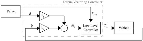
Figure 4.
TV control scheme of Chong et al. [].
To consider yaw moment limitations due to wheel slip that may be induced by excessive wheel torque, a control strategy with two components is proposed in []. The first controller is a wheel slip controller acting separately on each tire to maximize the produced force by limiting the applied torque and, consequently, the wheel slip. The second controller is a stability controller that generates a yaw moment proportional to the difference between the actual yaw acceleration and its desired value, inferred from the driver commanded steer angle rate. The torque distribution to each wheel is then performed according to the torque limit factors set by the traction controller. Similar contributions that incorporate an anti-skid controller into the torque vectoring logic can be found in [,,,].
To further adapt the controller to system non linearities and time-variant parameters, the authors of [] present a control strategy consisting in an inner-loop Anti-Skid Contribution (ASC) together with an outer-loop direct yaw moment contribution. The scheme of this controller is depicted in Figure 5. The advantage of the proposed controllers is that they are based on disturbance observers, eliminating the need for parameters such as vehicle velocity, sideslip angle or tire cornering stiffness, which can be challenging to measure or observe. The Direct Yaw Control (DYC) part of the control law generates a yaw moment () based on a Proportional–Integral (PI) controller that tracks a yaw rate reference value () dependent upon the steering input. Subsequently, the disturbance observer corrects the yaw moment by the PI controller to compensate for disturbances, defining the yaw moment () to be applied to the vehicle.
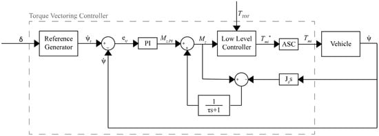
Figure 5.
TV control scheme of Fujimoto et al. [].
Since PID is a feedback control, many authors have suggested adding a feedforward contribution to allow a quicker system response. Indeed, while the feedback aims to guarantee robust stability and disturbance rejection, the feedforward contribution allows a faster system response [,,,,,,]. For instance, the authors in [] propose a control logic for vehicle lateral dynamics consisting of a feedforward and a feedback contribution, as depicted in Figure 6. The feedforward part is based on a multi-dimensional map containing the optimal yaw moment () required for the desired vehicle cornering response, also named as driving mode. The feedback contribution (), on the other hand, is based on a gain-scheduled PID controller tracking the yaw rate reference value specific to the selected driving mode, with an anti-windup contribution for the management of integral term saturation. The feedback gains are scheduled as a function of vehicle speed using a Particle Swarm Optimization (PSO) algorithm. An extension of the work is presented in [], where a dynamic feedforward contribution is added together with the Active Vibration Controller (AVC) from [] and the sideslip controller from []. This combination, used together with the suboptimal Second Order Sliding Mode (SOSM), defines the yaw rate and sideslip angle integrated controller. The purpose of the dynamic feedforward contribution is to modify the vehicle’s dynamic response without altering the steady-state gain in the static feedforward contribution. The design of this dynamic feedforward contribution is fulfilled through a transfer function that depends on front and rear axle cornering stiffness as well as on vehicle speed. For ease of implementation and to ensure stability, the scheduling is performed only on vehicle speed since cornering stiffness estimation can suffer from stability problems.
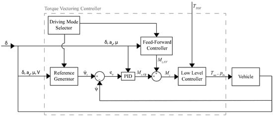
Figure 6.
TV control scheme of De Novellis et al. [].
When the tire–road friction is correctly estimated, a torque vectoring control acting on yaw rate error is sufficient to ensure vehicle stability. However, in the event of a drop in friction, there is the risk of tailspin. This risk can be mitigated by also controlling the vehicle sideslip angle together with the yaw rate []. Given that torque vectoring is a single actuation means with the need to fulfill two objectives (yaw rate and sideslip angle control), it is necessary to properly combine the two references into one single input to the system. This is fundamental since it can happen that the two targets conflict with each other. The authors in [,] proposed a Single-Input Single-Output (SISO) control strategy for vehicle lateral dynamics that aims to control both the yaw rate and vehicle sideslip angle. The approach is based on a yaw rate reference generator composed of two subsystems, as schematized in Figure 7. The first subsystem is the handling yaw rate generator that defines the vehicle cornering response () as a function of steering wheel angle and vehicle speed. The second subsystem applies a correction to the output of the first one based on the actual values of sideslip angle and yaw rate. Then, the error () between the reference-corrected yaw rate () and the actual yaw rate () becomes the input of a PI controller to generate the desired yaw moment (), which is then obtained by means of an even torque distribution strategy between front and rear wheels on the same vehicle side. The simulation results show that this approach can extend the stable region of vehicle operation. An alternative solution is proposed in [,], where a control strategy simultaneously controls vehicle sideslip angle and yaw rate by combining rear axle torque vectoring with Rear Wheel Steering (RWS). The definition of the yaw moment and of the rear wheels’ steering angle is performed by using four PI controllers in parallel, each one considering one actuator and tracking a single reference. The two results for the same actuator are then condensed in the control action through weighting coefficients. When control actions commanded by the yaw rate and the sideslip angle error are opposite, an anti-windup procedure is used to reset the integral parts of the controllers to avoid a slow response. Moreover, when a certain threshold of vehicle sideslip angle is exceeded, the yaw rate control is deactivated to ensure vehicle stability, accepting a slight degradation in performances. Using state portraits, the effects of the two controllers on modifying lateral dynamics are studied, and a performance index is assigned to them, acting as the weight for control actions. Performance index maps are generated offline for different combinations of front steering angle and vehicle speed values, but only for a small portion of the phase portrait about the equilibrium point.
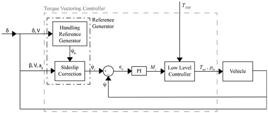
Figure 7.
TV control scheme of Lenzo et al. [,].
Torque vectoring is widely regarded as an effective tool in improving vehicle dynamics, prompting the design of controllers that also address uncommon road-driving situations. In [], a controller assisting the driver during drift maneuvers is proposed by imposing an appropriate yaw moment through torque vectoring at the rear axle, according to the scheme of Figure 8. To define a suitable control strategy, the effects of steering angle, gas pedal and torque vectoring on vehicle lateral dynamics were studied. The steering wheel angle has a strong influence in all driving conditions, with the gas pedal having comparable effects only in drifting conditions, and torque vectoring being able to control the yaw rate in any condition. This analysis explains why, instead of modifying driver inputs like steering angle and gas pedal, it is better to assist him by using torque vectoring. The yaw moment generated by the controller is proportional to the yaw index (YI) as in [], and it is activated only when the drift condition is detected, meaning a precise series of inputs coming from the driver related to the actual vehicle yaw rate. Trying to minimize the value of the yaw index, as done here, means trying to maintain the vehicle close to steady-state cornering, or equivalently, to prevent excessive increases in lateral velocity. In fact, the yaw index () is defined as follows:
where is the vehicle lateral acceleration, is the vehicle forward speed and is the yaw rate. The developed control strategy relies only on measured quantities, making it robust and not requiring any kind of estimator.
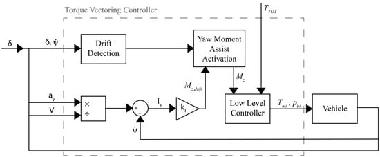
Figure 8.
TV control scheme of Vignati et al. [].
Other contributions, similar to the ones presented above, are reported in Table 1, where the most innovative aspects of each paper at the time of writing are highlighted.

Table 1.
Proportional–Integral–Derivative torque vectoring controllers.
2.2.2. Optimal Controllers
Optimal controllers are model-based controllers. Therefore, in contrast to PID regulators, they require a vehicle model and often an estimation of vehicle states for proper operation. The effectiveness of these controllers strongly depends on vehicle model reliability and on the capability to estimate model parameters, such as the tire–road friction coefficient. Moreover, obtaining the controller optimality conditions demands a thorough and precise knowledge of the system. Indeed, disturbances together with the variance in parameters can significantly impact both the performance and stability of the controller. Various techniques have been proposed in the literature to achieve optimal solutions, with the most common being LQR, LQG, LPV and numerical optimization tools. Linear Quadratic Regulators (LQRs) are optimal controllers aiming at the minimization of a quadratic cost function, which usually includes terms for vehicle state deviation from the reference and terms for actuation effort in torque vectoring applications. The typical plant model for these applications is either linear or linearized and expressed in state–space formulation. Letting represent the desired state vector, the actual state vector and the control input vector, the quadratic cost function () is defined as:
where is a symmetric and positive semi-definite matrix that weights state deviation in the cost definition and is a symmetric and positive definite matrix that weights the actuation effort. The gains for this controller type are derived for a linear system by solving the corresponding Riccati equation. Nevertheless, LQRs are highly sensitive to both modelling errors and disturbances, leading to the introduction of a Linear Quadratic Gaussian (LQG) controller, which models uncertainties as Gaussian noise. A limitation of both techniques is their reliance on linear models despite vehicles’ strong non-linear dynamics, which oblige the control designer to adopt a linearized vehicle model. Linearization can be alternatively performed only once at the beginning of the control process or cyclically at each iteration step. The latter approach requires a great computational effort but offers improved performance since the linearized model better represents the actual vehicle dynamics. Another tool ensuring controller stability even in the case of changes in vehicle parameters is the Linear Parameter Varying (LPV) modelling, which allows the synthesis of the optimal controller considering confidence ranges for key vehicle parameters.
All described optimal controller types adhere to a uniform scheme, as illustrated in Figure 9, where the only difference lies in the optimization algorithm. Additionally, the objective functions may vary, commonly focusing on:
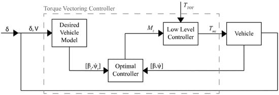
Figure 9.
Typical optimal TV control scheme.
- state reference tracking, where the controller aims to follow a reference for yaw rate () and/or sideslip angle ();
- energy consumption minimization, which may or may not involve following a reference in yaw rate and/or sideslip angle, sometimes also considering the low-level distribution of torques in the optimization routine.
Significant contributions to the field of torque vectoring optimal control are summarized in Table 2, highlighting the unique aspects of each study.
Table 2.
Optimal torque vectoring controllers.
2.2.3. Sliding Mode Controllers
Sliding Mode Control (SMC) is a discontinuous control technique that translates control objectives for a given plant into state constraints, typically forming a sliding surface for system state evolution. Usually, the sliding surface is defined with the objective of following the reference states for the system, and upon reaching this surface, the system state evolves by “sliding” over it. This type of controller is considered robust against modelling uncertainties but has the drawback of being continuously active when applied to vehicles for torque vectoring control. The output of the control strategy in its classical formulation can assume only a null or an arbitrary high value, meaning the control is a switching control that most of the times causes actuator saturation, which is then responsible for the typical chattering behavior. This issue is traditionally mitigated by low-pass filtering the control action or by performing the SMC at an integral or at a second-order level to produce a continuous control action.
Even in the case of sliding mode control, variations in vehicle parameters can impact the control strategy performance. In this light, the authors of [] presented a Variable Torque Distribution (VTD) Direct Yaw Control (DYC) strategy that uses rear axle torque vectoring while adjusting front-to-rear axle torque distribution for extending the linear vehicle response region. The yaw moment to track the neutral steering response of the linearized single-track reference vehicle model is obtained using a sliding mode control due to its robustness against the controlled plant’s non-linearities. For an increased robustness, the controller gains have been tuned according to the operational range for vehicle parameters, which are obtained through an uncertainty analysis. Challenges such as motor torque limitation and tire saturation are addressed in the controller design, with the tire control force limited according to the friction ellipse concept to reduce tire saturation occurrences.
In view of avoiding discontinuous control, the Second Order Sliding Mode (SOSM) is applied, defining the control action’s first time derivative with a switching function. A contribution in this field comes from [], where a torque vectoring control strategy for a vehicle equipped with a Rear Active Differential (RAD) is proposed. The controller combines feedforward and feedback contributions designed based on a single-track vehicle model according to the scheme in Figure 10. The feedforward contribution improves the transient response, while the feedback contribution ensures robust stability. In particular, the aim of this paper is to compare two different techniques for the robust feedback control, which are Internal Model Control (IMC) and second order sliding mode. The feedforward controller determines the control yaw moment through a linear filter built to match the desired open-loop yaw rate behavior of the vehicle. The IMC feedback controller is designed based on an H∞ approach to guarantee robustness in presence of model uncertainties and adding an anti-windup part to account for actuator saturation. The SOSM feedback controller, instead, is designed using the yaw rate error as sliding variable (), with the first-time derivative of the yaw moment () that is defined using the typical sliding mode switching function. This guarantees that a continuous control action () can be achieved, by moving the discontinuity to its first time derivative, while retaining the same robustness against uncertainties that are typical of first order sliding mode control. The desired yaw moment is then generated by setting the RAD locking torque ().
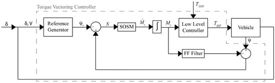
Figure 10.
TV control scheme by Canale et al. [].
When controlling multiple states, decoupling them and employing parallel control logics allows the definition of several control actions, also presenting the possibility of dealing with multiple actuators. This type of approach is schematized in Figure 11 according to the controller developed in [], where a control strategy is proposed to jointly determine the control actions to be allocated to Active Rear Steering (ARS) and direct yaw moment control, avoiding any implicit allocation algorithm. A Multiple-Input Multiple-Output (MIMO) sliding mode controller, based on a linear single-track vehicle model, is designed for simultaneously tracking vehicle sideslip angle and yaw rate references. The proposed MIMO sliding mode controller adopts separate switching functions for each state, considering the coupled yaw and lateral dynamics. Moreover, the controller replaces the sign function from the classical sliding mode theory with a saturation function to smoothen out the control action.
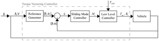
Figure 11.
TV control scheme by Fu et al. [].
Table 3 presents additional findings on torque vectoring sliding mode control, outlining the peculiarities and order of the SMC method used in each study.
Table 3.
Sliding mode torque vectoring controllers.
2.2.4. Model Predictive Controllers
Model Predictive Control (MPC) is a widely employed control framework for the solution of non-linear constrained optimal control problems. Similarly to optimal control techniques presented before, the primary objective is to achieve a suitable balance between tracking ability and actuation effort. However, a distinctive feature lies in the fact that the optimization problem is addressed within a finite time horizon, as opposed to an infinite duration. This similarity with optimal controllers is also evident when examining their typical scheme illustrated in Figure 12. MPC relies on a dynamic model of the system and employs the receding horizon control principle to predict the future response. At each control cycle, a series of control actions to be applied for the predictive horizon is calculated, with only the first one actually applied to the system. The computation of the control input profile is iteratively updated at each control step, incorporating new information from sensors. Consequently, the computational burden of this technique is substantial when compared to classic control strategies. Hence, due to the rapid nature of vehicle dynamics, implementing real-time control techniques was not feasible some years ago. Nonetheless, advancements in microprocessor technology and innovative computation algorithms now render this feasible.
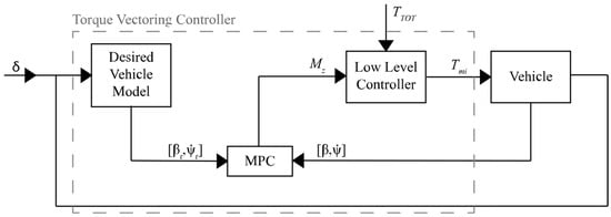
Figure 12.
Typical model predictive control TV control scheme.
Significant contributions in the field of model predictive control for vehicle lateral dynamics are reported in Table 4, which provides detailed descriptions of controller designs and the associated vehicle models used for this purpose.
Table 4.
Model predictive control torque vectoring controllers.
2.2.5. Fuzzy Controllers
Fuzzy logic is employed as a black-box approach to map an input space into an output space based on specific rules, often articulated in natural language. Typically, a fuzzy logic controller comprises three fundamental steps: fuzzification of inputs, processing of the fuzzified inputs, and defuzzification into outputs. The fuzzification of inputs consists in converting them into a qualitative value assuming a high or low value. The processing involves the application of the natural language rules established by the designer leveraging their knowledge about the system to be controlled to aggregate inputs into outputs. The defuzzification entails defining the control action according to output rules, still defined by the designer based on their knowledge. The application of this control process for vehicle lateral dynamics is illustrated in Figure 13.
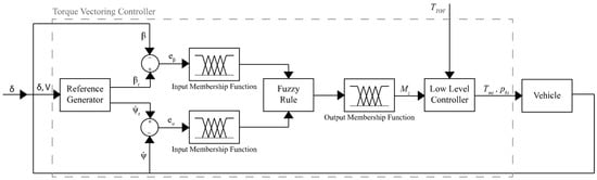
Figure 13.
Typical fuzzy TV control scheme.
Table 5 outlines various contributions in the literature related to torque vectoring control using fuzzy logic, where the fuzzy inference process proposed by each paper is described.
Table 5.
Fuzzy torque vectoring controllers.
2.3. Low-Level Controllers
The low-level controller defines the torque to be supplied by each motor to meet the total longitudinal force required by the driver and the desired yaw moment specified by the high-level controller. Several approaches are documented in the literature for this task, ranging from fixed distribution logics to optimized logics aiming at the equalization of tire workloads or at energy consumption minimization.
Fixed distribution logics, known for their simplicity in definition and implementation at the vehicle level, offer a straightforward approach. The simplest approach, applicable to 2WD vehicles, involves generating the desired yaw moment by allocating the torque to the driving wheels with the same magnitude and opposite sign []. This enables the application of TV with theoretically no energy consumption, as the power consumed on one side of the vehicle is recovered on the other side. The advanced version of fixed distribution algorithms for 4WD independently driven vehicles, instead, requires tuning a couple of parameters, namely the front-to-rear and left-to-right distributions, or, equivalently, the front-to-rear distribution for each side of the vehicle. A contribution from this field is presented in [], where the left-to-right distribution is fixed at the design stage, while the front-to-rear distribution is regulated through a PD controller on yaw rate error, accounting for the influence of longitudinal forces on vehicle lateral dynamics. Another example of rule-based distribution logic is presented in [], where a hierarchical approach using a decision tree is introduced. The concept is to generate the desired yaw moment by exploiting the maximum available friction at the minimum possible number of tires. Moreover, different tire selection orders are employed based on whether the actual vehicle yaw rate exceeds the reference value or not.
Much more interesting are the approaches dealing with the optimization of torque allocation to driving motors. As previously mentioned, two distinct methods can be identified: the first aims to minimize the imbalance of tire workloads, while the second focuses on minimizing energy consumption while ensuring a proper handling performance. Table 6 provides a summary of various contributions with the objective of defining an optimal torque allocation.
Table 6.
Optimal wheel torque allocation controllers.
3. Simulation Models
To enable a quantitative comparison among the various TV control methods previously discussed, some controllers for each method are considered and implemented in MATLAB/Simulink R2022b environment using a co-simulation approach featuring VI-Car Real Time for implementing the vehicle equations of motion. The simulation model accounts for the following elements:
- vehicle (14 DOFs);
- in-wheel electric motors (one per wheel);
- control strategy.
While the preceding paragraph extensively covered the aspect of control strategy, the current section provides a concise yet comprehensive overview of the controllers employed for simulation purposes. Three different high-level controllers are compared:
- LQR+YI;
- SOSM;
- PID+ISM.
It is noteworthy that the low-level controller, used for wheel torque allocation purposes and addressing tire forces saturation, remains consistent across all the high-level controllers that are the subjects of comparison.
3.1. Vehicle Model
The vehicle model is developed using VI-Grade CarRealTime 2022 software, thus accounting for five rigid bodies and 14 degrees of freedom. The rigid bodies consist of the four wheels and the vehicle chassis, while the degrees of freedom include:
- three displacements of the vehicle center of mass, namely x, y and z;
- three rotations about the principal axes passing through the vehicle center of mass, namely yaw, pitch and roll;
- four vertical displacements of unsprung masses;
- four wheel angular velocities about the hub axis.
This modeling approach addresses typical non-linearities in vehicle behavior, such as those associated with suspension elasto-kinematics, by incorporating multiple look-up tables. This enables achieving high fidelity without necessitating a substantial increase in the number of bodies and degrees of freedom. A detailed model including all the links and bodies present in the actual vehicle would otherwise require such an increase. For the present study, the vehicle parameters have been tuned to replicate a D-segment passenger car. The main vehicle data are reported in Table 7.
Table 7.
Main vehicle data.
Tires are modelled based on the Pacejka MF-Tire model []. The specific version employed in this paper is the PAC2002, which accounts both for combined slip conditions and relaxation lengths.
The driver model is the one embedded into VI-CarRealTime, employing a single-track model-based predictive control technique to define driver inputs. Given a target trajectory, the controller defines a connecting contour compatible with the initial position and orientation of the vehicle, smoothly linking to the reference trajectory at a predetermined preview distance. Subsequently, this connecting contour is used as a dynamic vehicle trajectory, imposed as input, ultimately leading to the computation of the corresponding steering control action through the inversion of equations.
3.2. Electric Motor Model
The four in-wheel electric motors driving the vehicle are modelled from a mechanical point of view. Figure 14 illustrates the motor mechanical characteristics in terms of torque versus speed, establishing upper and lower bounds for the available motor torque in the simulation. The dynamics of the motor, coupled with the electronic drive, is introduced through a first-order time lag transfer function () of the form:
where denotes the time constant. This transfer function is employed by providing the desired steady-state motor torque () as input and obtaining the actual motor torque () as output, ensuring adherence to the actual system dynamics.
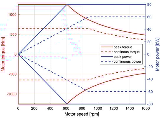
Figure 14.
IWM mechanical characteristic curves.
3.3. Control Strategy
Among the wide variety of controllers presented for the high-level control task associated with yaw moment definition, three have been selected for comparison. The common objective for each controller is to track the same state reference quantities, enabling a direct comparison of simulation results.
3.3.1. References
The proposed controllers aim to control both yaw rate and sideslip angle, thus, necessitating the definition of references for both these quantities. Concerning the yaw rate reference, it is determined according to Equation (5), considering an understeering coefficient , a maximum lateral acceleration and a limit lateral acceleration for the vehicle linear response. The sideslip angle reference is defined according to Equation (7), where a limit sideslip angle is considered.
3.3.2. High-Level Yaw Moment Generator—Strategy 1
The first controller is an optimal controller from [], comprising the sum of a steady-state and a dynamic contribution.
The steady-state contribution () is obtained in the form of an LQR where the vehicle model is linearized at each time instant. This contribution is multiplied by the activation factor , which diminishes the steady-state contribution during transients. The dynamic contribution () relies on the yaw index (), directly associated with the vehicle understeer/oversteer behavior. This index is employed in a proportional controller to determine the appropriate yaw moment to be applied to the vehicle.
This control logic is denoted as LQR+YI henceforth.
3.3.3. High-Level Yaw Moment Generator—Strategy 2
The second control strategy is presented in [] and combines a suboptimal second order sliding mode for yaw rate control with a first order sliding mode for sideslip angle control.
The suboptimal second order sliding mode uses the sliding surface , defined as the difference between the actual yaw rate () and its reference value ().
This sliding surface is employed to define the yaw moment first time derivative ().
In particular, corresponds to the time of the last singular value of , meaning that . Similarly, the controller on the vehicle sideslip angle employs a sliding surface to define the control action (), characterized by a discontinuous term.
As before, corresponds to the time of the last singular value of , meaning that . The transition between the two control logics is managed by the multiplying factor , determined based on the actual value of vehicle sideslip angle.
Here, represents the error in the sideslip angle, and is a constant parameter selected by the designer. This control logic is referred to as SOSM hereafter.
3.3.4. High-Level Yaw Moment Generator—Strategy 3
The third control algorithm is from [] and computes the yaw moment () by combining a PID contribution () and a filtered integral sliding mode contribution (). The latter is obtained by filtering the yaw moment () derived by a standard sliding mode controller through a first-order transfer function with a time constant.
Here, the sliding variable is defined as the sum of the sliding surface , representing the difference between the actual and reference yaw rates, and of an integral sliding mode variable (). The latter also includes the time derivative of the yaw rate reference () in its definition.
This control logic has been enhanced with the incorporation of a proportional sideslip angle controller for better alignment with the other methods, and it is designated as PID+ISM moving forward.
3.3.5. Low-Level Torque Distribution Strategy
Concerning the low-level torque distribution logic, a uniform approach is adopted for all the simulations to ensure fairness in comparing different high-level controllers. The driving torque () specified by the driver through the throttle position is evenly distributed to the front axle across both wheels, given that the validated vehicle model represents a Front-Wheel Drive (FWD) car. The differential torque necessary to meet the yaw moment requirement is then added to the former contribution on the front axle and is the sole contribution on the rear axle. The left-to-right torque distribution on a given axle is performed with an even approach, where the torque allocated to the left and right motors to achieve the desired yaw moment is equal in magnitude and opposite in sign. Conversely, the front-to-rear torque distribution among axles is performed proportionally to the force that can be generated before saturating the axle, based on the friction circle principle. The axle saturation () is obtained as the average of the tire saturation factors () belonging to that axle. The tire saturation factor is defined as follows:
where is the vertical force at the i-th tire, while and are the longitudinal and lateral force at the i-th tire, respectively. The distribution factor between the front and rear axle is then determined as a function of the normalized front and rear axle saturations, ensuring their sum corresponds to the unit value.
Here, and represent the fraction of motor torque for yaw moment generation applied to the front and rear axles, respectively. Consequently, the torque allocated to each wheel is expressed as:
where is the mean wheel radius, is the mean vehicle half-track width, and the subscript for each IWM torque () first indicates the axle (F/R) and then the side concerning the vehicle’s forward travelling direction (R/L).
In this paper, the yaw moment defined by the high-level controller leverages the capabilities of 4 IWMs. However, the same high-level controllers can be effectively deployed to any vehicle featuring torque vectoring capabilities. This includes vehicles using brakes as actuators or also vehicles exploiting torque vectoring at only two wheels, such as those equipped with active differentials or featuring a pair of independent motors on a single axle. It is evident that a change in vehicle topology requires a redesign of the low-level controller according to the available actuators for yaw moment generation.
3.3.6. Controller Tuning
The three proposed controllers from the literature were tuned to attain similar performances in both steady-state and transient conditions. Given the combined tracking of yaw rate and sideslip angle, yaw rate is selected as the primary state variable for tracking, accepting larger errors in sideslip angle. The tuning aspect is crucial for evaluating the advantages and disadvantages of each of the presented controllers. However, it is essential to acknowledge that variations in vehicle dynamics with the compared controllers are certain due to their different nature.
4. Results
The effectiveness of the control strategies presented above is assessed through numerical simulations, encompassing both transient and steady-state maneuvers, spanning from open-loop to closed-loop modalities. These same maneuvers are simulated under both high friction (μ = 1.0) and low friction (μ = 0.4) conditions to comprehensively investigate the entire operational range during typical vehicle operation on the road.
4.1. Open-loop Maneuvers
The steady-state performance of the proposed controllers under high friction conditions is evaluated through an ISO 4138 [] steering pad constant speed maneuver, where the speed is kept constant at approximately 100 km/h. During this maneuver, the steering wheel angle increases at a constant rate up to 90 degrees within a 200-second timeframe. The selection of the maximum steering wheel angle is conducted through incremental adjustments in 5-degree steps until the selected vehicle reference response achieves a minimum of 99% of the maximum achievable lateral acceleration. The duration for increasing the steering wheel angle from straight to the maximum value is selected based on the authors’ prior knowledge to comply with the steady-state maneuver limits outlined in the ISO 4138 standard []. The results of these simulations are reported in Figure 15.
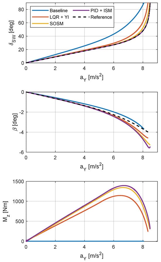
Figure 15.
Steering pad constant speed maneuver on high friction road (μ = 1).
Analyzing the quasi-steady-state simulations under high friction conditions, it is evident that the handling properties of the uncontrolled vehicle have been improved. All controllers demonstrate the ability to increase the maximum achievable lateral acceleration, ensuring a more responsive vehicle at low lateral acceleration while still guaranteeing a smooth vehicle behavior. The SOSM and PID+ISM controllers closely track the reference for steering angle against lateral acceleration or, equivalently, yaw rate. In contrast, the LQR+YI controller deviates from the yaw rate reference due to conflicting objectives related to concurrent yaw rate and sideslip angle reference tracking. However, the LQR+YI controller excels in drivability at handling limits, providing a smooth increase in vehicle sideslip angle and thus a more predictable behavior for the driver. On the other hand, SOSM and PID+ISM generate results that are farther from the sideslip angle reference, and this is expected since that variable becomes progressively controlled when the sideslip angle increases. Given the consistent reference across all the controllers, the observed differences across them are attributed to variations in the proportional weight of errors on yaw rate and sideslip angle, reflecting the different tuning requirements of each controller.
The steady-state performances of the same controllers under low friction conditions are still evaluated using a steering pad constant speed maneuver at 70 km/h, progressively increasing the steering angle at a constant rate up to 60 degrees within 200 seconds. Once again, the selection of the maximum steering wheel angle is based on achieving the maximum steady-state lateral acceleration performance of the reference vehicle. The execution time for the maneuver is maintained constant to ensure quasi-steady-state conditions, especially in more challenging scenarios, such as on surfaces with reduced friction. The results of these simulations are presented in Figure 16.
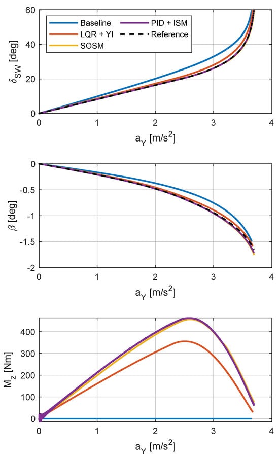
Figure 16.
Steering pad constant speed maneuver on low friction road (μ = 0.4).
Under low friction conditions, similar considerations to those under high friction apply. The main difference is the reduced variation between the three control strategies due to the lower margin against the total available friction which can be exploited to modify the vehicle handling characteristics. Drawing conclusions, it can be asserted that the LQR+YI controller has the potential to enhance steady-state vehicle dynamics. However, its dependence on a linearized vehicle model prevents it attaining optimal performance at handling limits. Conversely, both the SOSM and the PID+ISM controllers enhance steady-state vehicle dynamics, even in proximity of handling limits, with the PID+ISM controller exhibiting a superior yaw rate tracking performance. However, the PID+ISM controller induces a sudden variation in sideslip angle at handling limits, particularly under high-friction conditions. Consequently, the SOSM controller emerges as the preferable choice, as it achieves good handling performance while ensuring the predictability of the vehicle’s behavior. This quality translates to enhanced drivability, making the SOSM controller a more suitable option.
Transient performances of the controllers under high friction conditions are assessed using an ISO 7401 [] step steer maneuver, starting in straight line at 100 km/h and applying a sudden steer of 60 degrees while maintaining a fixed throttle position. The steering wheel angle at the end of the maneuver is predetermined, while the speed is systematically incremented in 10 km/h steps, stopping just before the point where the baseline vehicle could no longer complete the maneuver due to tailspin. The results for these maneuvers on high friction surface are reported in Figure 17.
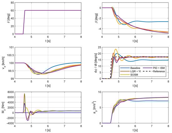
Figure 17.
Step steer maneuver on high friction road (μ = 1).
Examining the simulated transient maneuver under high friction conditions, torque vectoring, irrespective of the algorithm, enhances yaw rate and lateral acceleration responses compared to the uncontrolled vehicle. Regarding the yaw rate, the controlled vehicle damps out oscillations faster than the baseline vehicle. Moreover, the PID+ISM controller strongly reduces the yaw rate overshoot, while the other controllers are not able to do this. In general, the vehicle sideslip angle is also much smoother for the controlled vehicle than for the uncontrolled one, meaning easier handling for the driver. The SOSM is the worst performing controller in this scenario, generating oscillations in both yaw rate and sideslip angle responses. Notably, the SOSM controller exhibits a larger yaw rate overshoot than the uncontrolled vehicle, with yaw rate oscillations also not being better dampened out.
The transient performances of the controllers under low friction conditions are also assessed using a step steer maneuver, starting from a speed of 70 km/h and applying a sudden steer of 60 degrees while maintaining a fixed throttle position. The criteria for selecting the speed and the steering wheel angle at the conclusion of the maneuver align with those applied for the high-friction maneuver. The results for these maneuvers on low friction surface are presented in Figure 18.
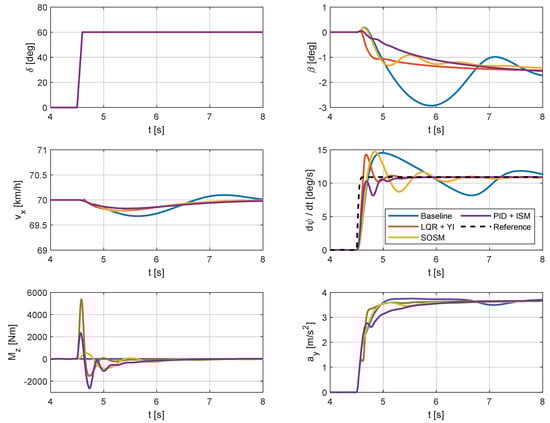
Figure 18.
Step steer maneuver on low friction road (μ = 0.4).
Under low friction conditions, the lateral acceleration achieved by the controlled vehicle is comparable to that of the uncontrolled vehicle. In this case, the LQR+YI controller generates a peaky overshoot of yaw rate and a rapid increase in the vehicle sideslip angle. This may cause drivability issues for the driver, who may not be prepared to react to such a sudden variation in vehicle handling properties. The SOSM controller achieves a similar yaw rate overshoot to the uncontrolled vehicle but settles to the steady-state value faster and with smaller oscillations in the vehicle sideslip angle. The PID+ISM controller outperforms the other methods, guaranteeing no overshoot in yaw rate and providing a smooth shape of the vehicle sideslip angle, contributing to ease the vehicle handling.
4.2. Close-Loop Maneuvers
Transient performances of the proposed controllers are assessed through steering wheel closed-loop simulations involving an ISO 3888 [] double lane-change maneuver. Under high friction conditions, the vehicle enters the testing track at 125 km/h and maintains that speed throughout the maneuver; meanwhile, under low friction conditions, the speed is set to 90 km/h. The maneuver speed is determined by incrementing it in 5 km/h steps and halting the process when the baseline vehicle strikes at least one cone of the ISO 3888 [] test course. The results for high friction and low friction conditions are presented in Figure 19 and Figure 20, respectively.
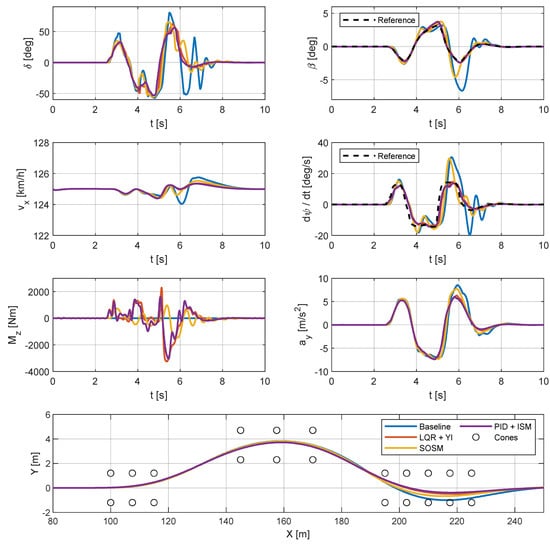
Figure 19.
Double lane-change maneuver on high friction road (μ = 1).
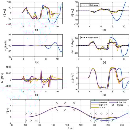
Figure 20.
Double lane-change maneuver on low friction road (μ = 0.4).
Upon examining the results under both high and low friction conditions, it is evident that the uncontrolled vehicle struggles to maintain the course, while the controlled ones successfully complete the maneuver without striking any cones in the last section of the test track. Particularly under low friction conditions, the uncontrolled vehicle exhibits strong oscillations even after completing the maneuver, while the controlled vehicle remains safely stable. In both low and high friction conditions, an undesirable interaction is observed between the SOSM torque vectoring controller and the steering wheel angle controller. Indeed, at the most critical point of the maneuver, there is a slightly oscillating behavior in the steering angle, yaw rate and vehicle sideslip angle time histories. Nevertheless, this undesired oscillation is promptly dampened out through proper steering wheel angle correction. Aside from these issues, all the controllers can effectively track the reference quantities for yaw rate and sideslip angle, resulting in a vehicle that is safer and easier to drive compared to the baseline one. Overall, the PID+ISM controller emerges as the top-performing option, slightly surpassing the performance of the LQR+YI controller, particularly in proximity to the maximum achievable lateral acceleration.
5. Conclusions
A review of direct yaw moment control techniques available in the literature is performed in this article. To ensure proper reliability, most of these techniques employ feedback controllers. Nevertheless, it has been demonstrated that incorporating a feedforward component into the control action is beneficial for achieving a fast response. The simplest approach to vehicle direct yaw moment control relies on PID controllers, known for their ease of design and tuning, as well as their robustness against external disturbances. The primary drawback lies in potential stability issues arising from unmodeled dynamics at the tuning stages. Modelling uncertainties can instead be properly handled by sliding mode controllers, which employ a discontinuous control technique. Nonetheless, this discontinuity poses a significant disadvantage in vehicle lateral dynamics control as it can lead to substantial vehicle oscillations. Several strategies have been proposed over the years to mitigate this effect, although they profoundly influence the controller’s nature and disturbance rejection capabilities. The controllers recognized for achieving the best performances are optimal controllers, which require a vehicle model for properly working. Consequently, their actual performance is heavily dependent on the vehicle model reliability. This also explains the evolution from LQR, sensitive to both modelling errors and external disturbances, to LQG, which models uncertainties as Gaussian noise, and LPV vehicle modelling, incorporating confidence ranges for main vehicle parameters. Similarly, Model Predictive Control (MPC) addresses optimization problems over a finite time horizon, distinguishing itself from infinite horizon optimization typical for optimal controllers. This feature makes MPC superior to infinite horizon optimization methods since the dynamics predicted by the adopted vehicle model are much more reliable over a short time horizon. However, it comes at the cost of a high computational power for real-time implementation, which is now becoming available thanks to technological advancements. At last, it is worth mentioning fuzzy logic control, which does not rely on any vehicle model but only on the designer’s knowledge. This characteristic, while offering flexibility, makes it challenging to ensure proper stability across various driving conditions.
In the second part of the paper, some of the presented yaw moment control techniques are tested on an electric vehicle with four independent motors, one for each wheel. The testing maneuvers range from steady-state to transient ones under both high and low friction conditions. The comparison highlights that, in steady-state conditions, the results in terms of yaw rate tracking are similar for the proposed algorithms. Nevertheless, some differences arise due to the variation in relative weights of yaw rate and sideslip angle errors in defining the control action. This happens because, in many situations, the two tracking objectives are conflicting, and thus, to define a single control action, it is necessary to make a compromise between them. In general, accepting decreased handling performance in yaw rate tracking is necessary to achieve a safer and more predictable vehicle in which sideslip angle is prevented from an excessive increase. Moreover, different kinds of controllers have different tuning requirements for being stable and robust against uncertainties, further contributing to differences in controller performances. Overall, the most effective torque vectoring controller among the compared ones is the PID+ISM, with its primary strength lying in its high responsiveness and robustness against disturbances. In contrast, the LQR+YI controller has worse performances at handling limits and during fast transients due to its dependency on a linearized vehicle model, which does not accurately represent the vehicle dynamics in extreme conditions. On the other hand, the SOSM controller is susceptible to inducing oscillations in extreme conditions due to its discontinuous nature. Indeed, looking at close-loop driving maneuvers, it is also possible to notice bad interactions between the SOSM torque vectoring controller and the driver, potentially causing an undesired vehicle behavior. For this reason, future works will concentrate on the interaction between vehicle handling control logics and human drivers using a dynamic driving simulator.
Author Contributions
M.A.: methodology, software, formal analysis, writing—original draft preparation, and writing—review and editing; M.V.: conceptualization, resources, writing—review and editing; E.S.: conceptualization, supervision. All authors have read and agreed to the published version of the manuscript.
Funding
This research received no external funding.
Conflicts of Interest
The authors declare no conflicts of interest.
Nomenclature
| Acronyms | |
| 4WD | Four-Wheel Drive |
| 4WS | Four-Wheel Steering |
| AFS | Active Front Steering |
| ANFIS | Adaptive Neuro-Fuzzy Inference System |
| ARS | Active Rear Steering |
| ASC | Anti-Skid Controller |
| ASOSM | Adaptive Second Order Sliding Mode |
| AVC | Active Vibration Controller |
| BTV | Brake Torque Vectoring |
| C/GMRES | Continuation/Generalized Minimal Residual |
| DOF | Degree Of Freedom |
| DYC | Direct Yaw moment Control |
| EHB | Electro-Hydraulic Brake |
| EV | Electric Vehicle |
| FB | Feed Back |
| FF | Feed Forward |
| FMPC | Fast Model Predictive Control |
| FWD | Front-Wheel Drive |
| HIL | Hardware-In-the-Loop |
| IMC | Internal Model Control |
| ISM | Integral Sliding Mode |
| IWM | In-Wheel Motor |
| KMPC | Koopman-operator Model Predictive Control |
| LMIs | Linear Matrix Inequalities |
| LPV | Linear Parameter Varying |
| LQG | Linear Quadratic Gaussian |
| LQR | Linear Quadratic Regulator |
| LTI | Linear Time-Invariant |
| MIMO | Multiple-Input Multiple-Output |
| MISO | Multiple-Input Single-Output |
| MMC | Model Matching Controller |
| MMM | Milliken Moment Method |
| MPC | Model Predictive Control |
| NLPC | Non-Linear Predictive Control |
| NMPC | Non-linear Model Predictive Control |
| NP | Nearest Point |
| P | Proportional |
| PD | Proportional–Derivative |
| PI | Proportional–Integral |
| PID | Proportional–Integral–Derivative |
| PSO | Particle Swarm Optimization |
| QP | Quadratic Programming |
| RAD | Rear Active Differential |
| RL | Reinforcement Learning |
| RLQR | Robust Linear Quadratic Regulator |
| RWS | Rear Wheel Steering |
| SAT | Self-Aligning Torque |
| SISO | Single-Input Single-Output |
| SMC | Sliding Mode Control |
| SOSM | Second Order Sliding Mode |
| TV | Torque Vectoring |
| TVC | Torque Vectoring Control |
| VTD | Variable Torque Distribution |
| YI | Yaw Index |
| Symbols | |
| Vehicle longitudinal acceleration | |
| Vehicle lateral acceleration | |
| Vehicle lateral acceleration at linear handling limit | |
| Maximum achievable vehicle lateral acceleration | |
| Distance between the front axle and the vehicle center of mass | |
| Distance between the rear axle and the vehicle center of mass | |
| Vehicle sideslip angle | |
| / | Vehicle sideslip angle reference |
| Maximum vehicle sideslip angle to achieve with the control | |
| Wheel steering angle | |
| Wheel steering angle at linear handling limit | |
| Wheel kinematic steering angle | |
| Wheel dynamic steering angle | |
| Steering wheel angle | |
| Rear wheels steering angle | |
| Error between actual and reference vehicle sideslip angle | |
| Error between actual and reference vehicle yaw rate | |
| Longitudinal force at the ith tire | |
| Lateral force at the ith tire | |
| Vertical force at the ith tire | |
| Vehicle center of mass height from ground | |
| Yaw index | |
| Vehicle yaw moment of inertia | |
| Front axle cornering stiffness | |
| Rear axle cornering stiffness | |
| Understeering coefficient | |
| Vehicle understeer gradient | |
| Yaw index proportional gain in LQR+YI controller | |
| Vehicle yaw rate gain in SOSM controller | |
| Vehicle sideslip angle gain in SOSM controller | |
| Vehicle sliding mode gain in PID+ISM controller | |
| Vehicle wheelbase | |
| Vehicle mass | |
| Yaw moment | |
| Feedforward yaw moment | |
| Feedback yaw moment | |
| Yaw moment to be applied to assist the drift condition | |
| Yaw moment required by LQR+YI controller | |
| Yaw moment required by LQR+YI steady-state contribution | |
| Yaw moment required by LWR+YI dynamic contribution | |
| Yaw moment required by SOSM controller | |
| Yaw moment required by SOSM controller due to sideslip angle contribution | |
| Yaw moment required by SOSM controller due to yaw rate contribution | |
| Yaw moment required by PID+ISM controller | |
| Yaw moment required by PID+ISM controller due to its sliding mode part | |
| Yaw moment required by PID+ISM controller obtained by filtering the sliding mode contribution | |
| Yaw moment required by PID+ISM controller due to its PID part | |
| ith caliper brake pressure | |
| Logics transition factor in SOSM controller | |
| Logics transition factor tuning parameter in SOSM controller | |
| Mean wheel effective rolling radius | |
| Vehicle yaw rate | |
| / | Vehicle yaw rate reference |
| Vehicle yaw rate at linear handling limit | |
| Maximum achievable vehicle yaw rate | |
| Vehicle yaw rate handling reference | |
| Sliding surface | |
| Vehicle yaw rate-related sliding surface | |
| Vehicle sideslip angle-related sliding surface | |
| ith axle force capability saturation | |
| ith wheel force capability saturation | |
| Front/Rear torque distribution factor | |
| Mean vehicle half track | |
| Vehicle front track half-width | |
| Vehicle rear track half-width | |
| Time corresponding to the last singular value of yaw rate-related sliding surface | |
| Time corresponding to the last singular value of sideslip angle-related sliding surface | |
| Net driving torque required by the driver | |
| ith motor driving torque | |
| Driving torque allocated to Front Right (FR) motor | |
| Driving torque allocated to Front Left (FL) motor | |
| Driving torque allocated to Rear Right (RR) motor | |
| Driving torque allocated to Rear Left (RL) motor | |
| Active differential locking torque | |
| Electric motor time constant | |
| Control input vector | |
| Tire–road friction coefficient | |
| Vehicle speed | |
| Vehicle state | |
| Vehicle reference state | |
| Actual state vector | |
| Desired state vector | |
| Integral sliding mode variable in PID+ISM controller | |
| Dynamic contribution activation factor in LQR+YI controller | |
References
- Massiani, J. Cost-Benefit Analysis of Policies for the Development of Electric Vehicles in Germany: Methods and Results. Transp. Policy 2015, 38, 19–26. [Google Scholar] [CrossRef]
- Requia, W.J.; Mohamed, M.; Higgins, C.D.; Arain, A.; Ferguson, M. How Clean Are Electric Vehicles? Evidence-Based Review of the Effects of Electric Mobility on Air Pollutants, Greenhouse Gas Emissions and Human Health. Atmos. Environ. 2018, 185, 64–77. [Google Scholar] [CrossRef]
- Rinderknechtw, S.; Meier, T. Electric Power Train Configurations and Their Transmission Systems. In Proceedings of the SPEEDAM 2010—International Symposium on Power Electronics, Electrical Drives, Automation and Motion, Pisa, Italy, 14–16 June 2010; pp. 1564–1568. [Google Scholar]
- Murata, S. Innovation by In-Wheel-Motor Drive Unit. Veh. Syst. Dyn. 2012, 50, 807–830. [Google Scholar] [CrossRef]
- Vignati, M.; Sabbioni, E.; Tarsitano, D.; Cheli, F. Electric Powertrain Layouts Analysis for Controlling Vehicle Lateral Dynamics with Torque Vectoring. In Proceedings of the 2017 International Conference of Electrical and Electronic Technologies for Automotive, Turin, Italy, 15–16 June 2017. [Google Scholar]
- De Novellis, L.; Sorniotti, A.; Gruber, P. Design and Comparison of the Handling Performance of Different Electric Vehicle Layouts. Proc. Inst. Mech. Eng. Part D J. Automob. Eng. 2014, 228, 218–232. [Google Scholar] [CrossRef]
- Vignati, M.; Sabbioni, E. Torque Vectoring Control for Different Powertrain Layouts of Hybrid and Electric Vehicles. In Proceedings of the Advanced Vehicle Control: Proceedings of the 13th International Symposium on Advanced Vehicle Control (AVEC’16), Munich, Germany, 13–16 September 2017; CRC Press/Balkema: Munich, Germany, 2017; pp. 637–644. [Google Scholar]
- Parra, A.; Zubizarreta, A.; Perez, J. A Comparative Study of the Effect of Intelligent Control Based Torque Vectoring Systems on EVs with Different Powertrain Architectures. In Proceedings of the 2019 IEEE Intelligent Transportation Systems Conference, ITSC 2019, Auckland, New Zealand, 27–30 October 2019; Institute of Electrical and Electronics Engineers Inc.: New York, NY, USA, 2019; pp. 480–485. [Google Scholar]
- Nagai, M.; Shino, M.; Gao, F. Study on Integrated Control of Active Front Steer Angle and Direct Yaw Moment. JSAE Rev. 2002, 23, 309–315. [Google Scholar] [CrossRef]
- Nagai, M.; Hirano, Y.; Yamanaka, S. Integrated Control of Active Rear Wheel Steering and Direct Yaw Moment Control. Veh. Syst. Dyn. 1997, 27, 357–370. [Google Scholar] [CrossRef]
- Wang, Y.; Nagai, M. Integrated Control of Four-Wheel-Steer and Yaw Moment to Improve Dynamic Stability Margin. In Proceedings of the IEEE Conference on Decision and Control, Kobe, Japan, 13 December 1996; Volume 2, pp. 1783–1784. [Google Scholar]
- Abe, M.; Ohkubo, N.; Kano, Y. A Direct Yaw Moment Control for Improving Limit Performance of Vehicle Handling—Comparison and Cooperation with 4WS. Veh. Syst. Dyn. 1996, 25, 3–23. [Google Scholar] [CrossRef]
- Vivas-López, C.A.; Hernandez-Alcantara, D.; Tudón-Martínez, J.C.; Morales-Menendez, R. Review on Global Chassis Control. IFAC Proc. Vol. 2013, 46, 875–880. [Google Scholar] [CrossRef]
- Aripin, M.K.; Md Sam, Y.; Danapalasingam, K.A.; Peng, K.; Hamzah, N.; Ismail, M.F. A Review of Active Yaw Control System for Vehicle Handling and Stability Enhancement. Int. J. Veh. Technol. 2014, 2014, 437515. [Google Scholar] [CrossRef]
- Mazzilli, V.; De Pinto, S.; Pascali, L.; Contrino, M.; Bottiglione, F.; Mantriota, G.; Gruber, P.; Sorniotti, A. Integrated Chassis Control: Classification, Analysis and Future Trends. Annu. Rev. Control 2021, 51, 172–205. [Google Scholar] [CrossRef]
- Katsuyama, E.; Yamakado, M.; Abe, M. A State-of-the-Art Review: Toward a Novel Vehicle Dynamics Control Concept Taking the Driveline of Electric Vehicles into Account as Promising Control Actuators. Veh. Syst. Dyn. 2021, 59, 976–1025. [Google Scholar] [CrossRef]
- De Novellis, L.; Sorniotti, A.; Gruber, P.; Shead, L.; Ivanov, V.; Hoepping, K. Torque Vectoring for Electric Vehicles with Individually Controlled Motors: State-of-the-Art and Future Developments. World Electr. Veh. J. 2012, 5, 617–628. [Google Scholar] [CrossRef]
- Shibahata, Y.; Shimada, K.; Tomari, T. Improvement of Vehicle Maneuverability by Direct Yaw Moment Control. Veh. Syst. Dyn. 1993, 22, 465–481. [Google Scholar] [CrossRef]
- Abe, M. Side-Slip Control to Stabilize Vehicle Lateral Motion by Direct Yaw Moment. JSAE Rev. 2001, 22, 413–419. [Google Scholar] [CrossRef]
- Wheals, J.C.; Baker, H.; Ramsey, K.; Turner, W. Torque Vectoring AWD Driveline: Design, Simulation, Capabilities and Control. In SAE Technical Papers; SAE International: Warrendale, PA, USA, 2004; Volume 2004. [Google Scholar]
- Hancock, M.J.; Williams, R.A.; Gordon, T.J.; Best, M.C. A Comparison of Braking and Differential Control of Road Vehicle Yaw-Sideslip Dynamics. Proc. Inst. Mech. Eng. Part D J. Automob. Eng. 2005, 219, 309–327. [Google Scholar] [CrossRef]
- Cheli, F.; Giaramita, M.; Pedrinelli, M.; Sandoni, G.; Travaglio, G.C. A New Control Strategy for a Semi-Active Differential (Part I). In Proceedings of the IFAC Proceedings Volumes (IFAC-PapersOnline), 1 January 2005; IFAC Secretariat: Helsinki, Finland, 2005; Volume 16, pp. 140–145. [Google Scholar]
- Resta, F.; Teuschl, G.; Zanchetta, M.; Zorzutti, A. A New Control Strategy for a Semi-Active Differential (Part II). In Proceedings of the IFAC Proceedings Volumes (IFAC-PapersOnline); IFAC Secretariat: Helsinki, Finland, 2005; Volume 16, pp. 146–151. [Google Scholar]
- Canale, M.; Fagiano, L.; Milanese, M.; Borodani, P. Robust Vehicle Yaw Control Using an Active Differential and IMC Techniques. Control Eng. Pract. 2007, 15, 923–941. [Google Scholar] [CrossRef]
- Cheli, F.; Cimatti, F.; Dellachà, P.; Zorzutti, A. Development and Implementation of a Torque Vectoring Algorithm for an Innovative 4WD Driveline for a High-Performance Vehicle. Veh. Syst. Dyn. 2009, 47, 179–193. [Google Scholar] [CrossRef]
- Yasui, Y.; Tozu, K.; Hattori, N.; Sugisawa, M. Improvement of Vehicle Directional Stability for Transient Steering Maneuvers Using Active Brake Control. SAE Trans. 1996, 105, 537–543. [Google Scholar]
- Nishio, A.; Tozu, K.; Yamaguchi, H.; Asano, K.; Amano, Y. Development of Vehicle Stability Control System Based on Vehicle Sideslip Angle Estimation. SAE Trans. 2001, 110, 115–122. [Google Scholar]
- Kakalis, L.; Cheli, F.; Sabbioni, E. The Development of a Brake Based Torque Vectoring System for a Sport Vehicle Performance Improvement. In Proceedings of the 6th International Conference on Informatics in Control, Automation and Robotics, ICSO, Milan, Italy, 2–5 July 2009; Volume 1, pp. 298–304. [Google Scholar] [CrossRef]
- Sabbioni, E.; Kakalis, L.; Cheli, F. On the Impact of the Maximum Available Tire-Road Friction Coefficient Awareness in a Brake-Based Torque Vectoring System. In SAE Technical Papers; SAE International: Warrendale, PA, USA, 2010. [Google Scholar]
- Ding, N.; Taheri, S. An Adaptive Integrated Algorithm for Active Front Steering and Direct Yaw Moment Control Based on Direct Lyapunov Method. Veh. Syst. Dyn. 2010, 48, 1193–1213. [Google Scholar] [CrossRef]
- Kobayashi, I.; Kuroda, J.; Uchino, D.; Ogawa, K.; Ikeda, K.; Kato, T.; Endo, A.; Peeie, M.H.B.; Narita, T.; Kato, H. Research on Yaw Moment Control System for Race Cars Using Drive and Brake Torques. Vehicles 2023, 5, 515–534. [Google Scholar] [CrossRef]
- Hajiloo, R.; Khajepour, A.; Kasaiezadeh, A.; Chen, S.K.; Litkouhi, B. A Model Predictive Control of Electronic Limited Slip Differential and Differential Braking for Improving Vehicle Yaw Stability. IEEE Trans. Control Syst. Technol. 2023, 31, 797–808. [Google Scholar] [CrossRef]
- Sakai, S.-I.; Sado, H.; Hori, Y. Dynamic Driving/Braking Force Distribution in Electric Vehicle with Independently Driven Four Wheels. IEEJ Trans. Ind. Appl. 2000, 120, 761–768. [Google Scholar] [CrossRef]
- Hallowell, S.J.; Ray, L.R. All-Wheel Driving Using Independent Torque Control of Each Wheel. In Proceedings of the 2003 American Control Conference, Denver, CO, USA, 4–6 June 2003; Volume 3, pp. 2590–2595. [Google Scholar]
- Esmailzadeh, E.; Goodarzi, A.; Vossoughi, G.R. Optimal Yaw Moment Control Law for Improved Vehicle Handling. Mechatronics 2003, 13, 659–675. [Google Scholar] [CrossRef]
- Fujimoto, H.; Saito, T.; Tsumasaka, A.; Noguchi, T. Motion Control and Road Condition Estimation of Electric Vehicles with Two In-Wheel Motors. In Proceedings of the IEEE International Conference on Control Applications, Taipei, Taiwan, 2–4 September 2004; Volume 2, pp. 1266–1271. [Google Scholar]
- Fujimoto, H.; Takahashi, N.; Tsumasaka, A.; Noguchi, T. Motion Control of Electric Vehicle Based on Cornering Stiffness Estimation with Yaw-Moment Observer. In Proceedings of the International Workshop on Advanced Motion Control, AMC, Istanbul, Turkey, 27–29 March 2006; Volume 2006, pp. 206–211. [Google Scholar]
- Kim, D.-H.; Kim, J.-M.; Hwang, S.-H.; Kim, H.-S. Optimal Brake Torque Distribution for a Four-Wheel-Drive Hybrid Electric Vehicle Stability Enhancement. Proc. Inst. Mech. Eng. Part D J. Automob. Eng. 2007, 221, 1357–1366. [Google Scholar] [CrossRef]
- Pinto, L.; Aldworth, S.; Watkinson, M.; Jeary, P.; Franco-Jorge, M. Advanced Yaw Motion Control of a Hybrid Vehicle Using Twin Rear Electric Motors. AVEC 2010, 10, 640–645. [Google Scholar]
- Li, S.; Wang, G.; Zhang, B.; Yu, Z.; Cui, G. Vehicle Yaw Stability Control at the Handling Limits Based on Model Predictive Control. Int. J. Automot. Technol. 2020, 21, 361–370. [Google Scholar] [CrossRef]
- Zhang, L.; Chen, H.; Huang, Y.; Wang, P.; Guo, K. Human-Centered Torque Vectoring Control for Distributed Drive Electric Vehicle Considering Driving Characteristics. IEEE Trans. Veh. Technol. 2021, 70, 7386–7399. [Google Scholar] [CrossRef]
- Tahami, F.; Farhangi, S.; Kazemi, R. A Fuzzy Logic Direct Yaw-Moment Control System for All-Wheel-Drive Electric Vehicles. Veh. Syst. Dyn. 2004, 41, 203–221. [Google Scholar] [CrossRef]
- De Novellis, L.; Sorniotti, A.; Gruber, P.; Pennycott, A. Comparison of Feedback Control Techniques for Torque-Vectoring Control of Fully Electric Vehicles. IEEE Trans. Veh. Technol. 2014, 63, 3612–3623. [Google Scholar] [CrossRef]
- Goggia, T.; Sorniotti, A.; De Novellis, L.; Ferrara, A. Torque-Vectoring Control in Fully Electric Vehicles via Integral Sliding Modes. In Proceedings of the American Control Conference, Portland, OR, USA, 4–6 June 2014; Institute of Electrical and Electronics Engineers Inc.: New York, NY, USA, 2014; pp. 3918–3923. [Google Scholar]
- De Novellis, L.; Sorniotti, A.; Gruber, P. Driving Modes for Designing the Cornering Response of Fully Electric Vehicles with Multiple Motors. Mech. Syst. Signal Process. 2015, 64–65, 1–15. [Google Scholar] [CrossRef]
- De Novellis, L.; Sorniotti, A.; Gruber, P.; Orus, J.; Rodriguez Fortun, J.M.; Theunissen, J.; De Smet, J. Direct Yaw Moment Control Actuated through Electric Drivetrains and Friction Brakes: Theoretical Design and Experimental Assessment. Mechatronics 2015, 26, 1–15. [Google Scholar] [CrossRef]
- Lu, Q.; Sorniotti, A.; Gruber, P.; Theunissen, J.; De Smet, J. H∞ Loop Shaping for the Torque-Vectoring Control of Electric Vehicles: Theoretical Design and Experimental Assessment. Mechatronics 2016, 35, 32–43. [Google Scholar] [CrossRef]
- Cheli, F.; Melzi, S.; Sabbioni, E.; Vignati, M. Torque Vectoring Control of a Four Independent Wheel Drive Electric Vehicle. In Proceedings of the ASME Design Engineering Technical Conference; American Society of Mechanical Engineers, Virtual, 12 February 2013; Volume 1, pp. 1–7. [Google Scholar]
- Mangia, A.; Lenzo, B.; Sabbioni, E. An Integrated Torque-Vectoring Control Framework for Electric Vehicles Featuring Multiple Handling and Energy-Efficiency Modes Selectable by the Driver. Meccanica 2021, 56, 991–1010. [Google Scholar] [CrossRef]
- Dizqah, A.M.; Lenzo, B.; Sorniotti, A.; Gruber, P.; Fallah, S.; De Smet, J. A Fast and Parametric Torque Distribution Strategy for Four-Wheel-Drive Energy-Efficient Electric Vehicles. IEEE Trans. Ind. Electron. 2016, 63, 4367–4376. [Google Scholar] [CrossRef]
- De Filippis, G.; Lenzo, B.; Sorniotti, A.; Gruber, P.; De Nijs, W. Energy-Efficient Torque-Vectoring Control of Electric Vehicles with Multiple Drivetrains. IEEE Trans. Veh. Technol. 2018, 67, 4702–4715. [Google Scholar] [CrossRef]
- Vignati, M.; Sabbioni, E.; Tarsitano, D. Torque Vectoring Control for IWM Vehicles. Int. J. Veh. Perform. 2016, 2, 302–324. [Google Scholar] [CrossRef]
- Lu, Q.; Gentile, P.; Tota, A.; Sorniotti, A.; Gruber, P.; Costamagna, F.; De Smet, J. Enhancing Vehicle Cornering Limit through Sideslip and Yaw Rate Control. Mech. Syst. Signal Process. 2016, 75, 455–472. [Google Scholar] [CrossRef]
- Lenzo, B.; Sorniotti, A.; Gruber, P. A Single Input Single Output Formulation for Yaw Rate and Sideslip Angle Control via Torque-Vectoring. In Proceedings of the 14th International Symposium on Advanced Vehicle Control (AVEC’ 18), Beijing, China, 16–20 July 2018. [Google Scholar]
- Lenzo, B.; Zanchetta, M.; Sorniotti, A.; Gruber, P.; De Nijs, W. Yaw Rate and Sideslip Angle Control through Single Input Single Output Direct Yaw Moment Control. IEEE Trans. Control Syst. Technol. 2021, 29, 124–139. [Google Scholar] [CrossRef]
- Chong, U.S.; Namgoong, E.; Sul, S.K. Torque Steering Control of 4-Wheel Drive Electric Vehicle. In Proceedings of the IEEE Workshop on Power Electronics in Transportation, Dearborn, MI, USA, 24–25 October 1996; pp. 159–164. [Google Scholar]
- Zhang, L.; Ding, H.; Huang, Y.; Chen, H.; Guo, K.; Li, Q. An Analytical Approach to Improve Vehicle Maneuverability via Torque Vectoring Control: Theoretical Study and Experimental Validation. IEEE Trans. Veh. Technol. 2019, 68, 4514–4526. [Google Scholar] [CrossRef]
- Yahagi, S.; Suzuki, M. Intelligent PI Control Based on the Ultra-Local Model and Kalman Filter for Vehicle Yaw-Rate Control. SICE J. Control. Meas. Syst. Integr. 2023, 16, 38–47. [Google Scholar] [CrossRef]
- Kasinathan, D.; Kasaiezadeh, A.; Wong, A.; Khajepour, A.; Chen, S.K.; Litkouhi, B. An Optimal Torque Vectoring Control for Vehicle Applications via Real-Time Constraints. IEEE Trans. Veh. Technol. 2016, 65, 4368–4378. [Google Scholar] [CrossRef]
- Wang, Z.; Montanaro, U.; Fallah, S.; Sorniotti, A.; Lenzo, B. A Gain Scheduled Robust Linear Quadratic Regulator for Vehicle Direct Yaw Moment Control. Mechatronics 2018, 51, 31–45. [Google Scholar] [CrossRef]
- Abe, M. Vehicle Dynamics and Control for Improving Handling and Active Safety: From Four-Wheel Steering to Direct Yaw Moment Control. J. Multi-Body Dyn. 1999, 213, 87–101. [Google Scholar] [CrossRef]
- Ding, S.; Liu, L.; Zheng, W.X. Sliding Mode Direct Yaw-Moment Control Design for In-Wheel Electric Vehicles. IEEE Trans. Ind. Electron. 2017, 64, 6752–6762. [Google Scholar] [CrossRef]
- Kim, D.; Kim, H. Vehicle Stability Control with Regenerative Braking and Electronic Brake Force Distribution for a Four-Wheel Drive Hybrid Electric Vehicle. Proc. Inst. Mech. Eng. Part D J. Automob. Eng. 2006, 220, 683–693. [Google Scholar] [CrossRef]
- Parra, A.; Zubizarreta, A.; Perez, J. A Novel Torque Vectoring Algorithm with Regenerative Braking Capabilities. In Proceedings of the IECON Proceedings (Industrial Electronics Conference), Lisbon, Portugal, 14–17 October 2019; Volume 2019, pp. 2592–2597. [Google Scholar]
- Falcone, P.; Tufo, M.; Borrelli, F.; Asgarit, J.; Tseng, H.E. A Linear Time Varying Model Predictive Control Approach to the Integrated Vehicle Dynamics Control Problem in Autonomous Systems. In Proceedings of the 2007 46th IEEE Conference on Decision and Control, New Orleans, LA, USA, 12–14 December 2007; pp. 2980–2985. [Google Scholar] [CrossRef]
- Liu, H.; Zhang, L.; Wang, P.; Chen, H. A Real-Time NMPC Strategy for Electric Vehicle Stability Improvement Combining Torque Vectoring with Rear-Wheel Steering. IEEE Trans. Transp. Electrif. 2022, 8, 3825–3835. [Google Scholar] [CrossRef]
- Taherian, S.; Kuutti, S.; Visca, M.; Fallah, S. Self-Adaptive Torque Vectoring Controller Using Reinforcement Learning. In Proceedings of the 2021 IEEE International Intelligent Transportation Systems Conference (ITSC), Indianapolis, IN, USA, 19–22 September 2021; pp. 172–179. [Google Scholar] [CrossRef]
- Deng, H.; Zhao, Y.; Lin, F.; Wang, Q. Deep Reinforcement Learning-Based Torque Vectoring Control Considering Economy and Safety. Machines 2023, 11, 459. [Google Scholar] [CrossRef]
- Johansen, T.A.; Fossen, T.I. Control Allocation—A Survey. Automatica 2013, 49, 1087–1103. [Google Scholar] [CrossRef]
- Singh, K.B.; Arat, M.A.; Taheri, S. Literature Review and Fundamental Approaches for Vehicle and Tire State Estimation. Veh. Syst. Dyn. 2019, 57, 1643–1665. [Google Scholar] [CrossRef]
- Jin, X.; Yin, G.; Chen, N. Advanced Estimation Techniques for Vehicle System Dynamic State: A Survey. Sensors 2019, 19, 4289. [Google Scholar] [CrossRef]
- Chindamo, D.; Lenzo, B.; Gadola, M. On the Vehicle Sideslip Angle Estimation: A Literature Review of Methods, Models, and Innovations. Appl. Sci. 2018, 8, 355. [Google Scholar] [CrossRef]
- Zhang, X.; Göhlich, D.; Fu, C. Comparative Study of Two Dynamics-Model-Based Estimation Algorithms for Distributed Drive Electric Vehicles. Appl. Sci. 2017, 7, 898. [Google Scholar] [CrossRef]
- Vignati, M.; Bravin, M.; Sabbioni, E. Control Strategy for Vehicle Lateral Dynamics Combining Torque Vectoring with Four Wheel Steering. In Proceedings of the ASME Design Engineering Technical Conference, Virtual, 25 November 2019; American Society of Mechanical Engineers (ASME): New York, NY, USA, 2019; Volume 3, pp. 1–7. [Google Scholar]
- Sun, Y.; Lee, R.; Tian, G. Torque Vectoring Control Strategies for Distributed Electric Drive Formula SAE Racing Car; SAE Technical Paper; SAE International: Warrendale, PA, USA, 2021. [Google Scholar] [CrossRef]
- Chae, M.; Hyun, Y.; Yi, K.; Nam, K. Dynamic Handling Characteristics Control of an In-Wheel-Motor Driven Electric Vehicle Based on Multiple Sliding Mode Control Approach. IEEE Access 2019, 7, 132448–132458. [Google Scholar] [CrossRef]
- Kwak, B.; Park, Y. Robust Vehicle Stability Controller Based on Multiple Sliding Mode Control. SAE Trans. 2001, 110, 514–520. [Google Scholar] [CrossRef]
- Sabbioni, E.; Cheli, F.; Vignati, M.; Melzi, S. Comparison of Torque Vectoring Control Strategies for a IWM Vehicle. SAE Int. J. Passeng. Cars–Electron. Electr. Syst. 2014, 7, 565–572. [Google Scholar] [CrossRef]
- Mousavinejad, E.; Han, Q.L.; Yang, F.; Zhu, Y.; Vlacic, L. Integrated Control of Ground Vehicles Dynamics via Advanced Terminal Sliding Mode Control. Veh. Syst. Dyn. 2017, 55, 268–294. [Google Scholar] [CrossRef]
- Hamzah, N.; Aripin, M.K.; Sam, Y.M.; Selamat, H.; Ismail, M.F. Vehicle Stability Enhancement Based on Second Order Sliding Mode Control. In Proceedings of the 2012 IEEE International Conference on Control System, Computing and Engineering, ICCSCE 2012, Penang, Malaysia, 23–25 November 2012; IEEE Computer Society: Washington, DC, USA, 2012; pp. 580–585. [Google Scholar]
- Canale, M.; Fagiano, L.; Ferrara, A.; Vecchio, C. Vehicle Yaw Control via Second-Order Sliding-Mode Technique. IEEE Trans. Ind. Electron. 2008, 55, 3908–3916. [Google Scholar] [CrossRef]
- Cho, J.; Huh, K. Torque Vectoring System Design for Hybrid Electric–All Wheel Drive Vehicle. Proc. Inst. Mech. Eng. Part D J. Automob. Eng. 2020, 234, 2680–2692. [Google Scholar] [CrossRef]
- Milliken, W.F.; Milliken, D.L. Race Car Vehicle Dynamics; SAE International: Warrendale, PA, USA, 1994; ISBN 978-1-56091-526-3. [Google Scholar]
- Song, C.; Xiao, F.; Song, S.; Li, S.; Li, J. Stability Control of 4WD Electric Vehicle with In-Wheel-Motors Based on Sliding Mode Control. In Proceedings of the 6th International Conference on Intelligent Control and Information Processing, ICICIP 2015, Wuhan, China, 20 January 2016; Institute of Electrical and Electronics Engineers Inc.: New York, NY, USA, 2016; pp. 251–257. [Google Scholar]
- Braghin, F.; Sabbioni, E.; Sironi, G.; Vignati, M. A Feedback Control Strategy for Torque-Vectoring of IWM Vehicles. In Proceedings of the ASME Design Engineering Technical Conference; American Society of Mechanical Engineers (ASME), Virtual, 13 January 2014; Volume 3. [Google Scholar]
- Ghike, C.; Shim, T.; Asgari, J. Integrated Control of Wheel Drive-Brake Torque for Vehicle-Handling Enhancement. Proc. Inst. Mech. Eng. Part D J. Automob. Eng. 2009, 223, 439–457. [Google Scholar] [CrossRef]
- Zhao, J.; Wong, P.K.; Ma, X.; Xie, Z. Chassis Integrated Control for Active Suspension, Active Front Steering and Direct Yaw Moment Systems Using Hierarchical Strategy. Veh. Syst. Dyn. 2017, 55, 72–103. [Google Scholar] [CrossRef]
- Parra, A.; Zubizarreta, A.; Pérez, J.; Dendaluce, M. Intelligent Torque Vectoring Approach for Electric Vehicles with Per-Wheel Motors. Complexity 2018, 2018, 8–12. [Google Scholar] [CrossRef]
- Fu, C.; Hoseinnezhad, R.; Li, K.; Hu, M.; Huang, F.; Li, F. Vehicle Integrated Chassis Control via Multi-Input Multi-Output Sliding Mode Control. In Proceedings of the ICCAIS 2018–7th International Conference on Control, Automation and Information Sciences, Hangzhou, China, 24–27 October 2018; pp. 355–360. [Google Scholar]
- Vignati, M.; Sabbioni, E. A Cooperative Control Strategy for Yaw Rate and Sideslip Angle Control Combining Torque Vectoring with Rear Wheel Steering. Veh. Syst. Dyn. 2021, 60, 1668–1701. [Google Scholar] [CrossRef]
- Jaafari, S.M.M.; Shirazi, K.H. Integrated Vehicle Dynamics Control via Torque Vectoring Differential and Electronic Stability Control to Improve Vehicle Handling and Stability Performance. J. Dyn. Syst. Meas. Control. 2018, 140, 071003. [Google Scholar] [CrossRef]
- De Novellis, L.; Sorniotti, A.; Gruber, P. Optimal Wheel Torque Distribution for a Four-Wheel-Drive Fully Electric Vehicle. SAE Int. J. Passeng. Cars–Mech. Syst. 2013, 6, 128–136. [Google Scholar] [CrossRef]
- Matsumoto, N.; Kuraoka, H.; Ohba, M. An Experimental Study on Vehicle Lateral and Yaw Motion Control. In Proceedings of the IECON Proceedings (Industrial Electronics Conference), Kobe, Japan, 28 October–1 November 1991; Volume 1, pp. 113–118. [Google Scholar]
- Ackermann, J.; Sienel, W. Robust Yaw Damping of Cars with Front and Rear Wheel Steering. IEEE Trans. Control Syst. Technol. 1993, 1, 15–20. [Google Scholar] [CrossRef]
- Ackermann, J. Robust Control Prevents Car Skidding. IEEE Control Syst. 1997, 17, 23–31. [Google Scholar]
- Ando, N.; Fujimoto, H. Yaw-Rate Control for Electric Vehicle with Active Front/Rear Steering and Driving/Braking Force Distribution of Rear Wheels. In Proceedings of the International Workshop on Advanced Motion Control, AMC, Nagaoka, Japan, 21–24 March 2010; Volume 131, pp. 726–731. [Google Scholar]
- Park, J.Y.; Heo, S.J.; Kang, D.O. Development of Torque Vectoring Control Algorithm for Front Wheel Driven Dual Motor System and Evaluation of Vehicle Dynamics Performance. Int. J. Automot. Technol. 2020, 21, 1283–1291. [Google Scholar] [CrossRef]
- Ivanov, V.; Savitski, D.; Orus, J.; Fortun, J.M.R.; Sorniotti, A.; Gruber, P. All-Wheel-Drive Electric Vehicle with on-Board Motors: Experimental Validation of the Motion Control Systems. In Proceedings of the IECON 2015–41st Annual Conference of the IEEE Industrial Electronics Society, Yokohama, Japan, 9–12 November 2015; Institute of Electrical and Electronics Engineers Inc.: New York, NY, USA, 2015; pp. 1729–1734. [Google Scholar]
- Lenzo, B.; Sorniotti, A.; Gruber, P.; Sannen, K. On the Experimental Analysis of Single Input Single Output Control of Yaw Rate and Sideslip Angle. Int. J. Automot. Technol. 2017, 18, 799–811. [Google Scholar] [CrossRef]
- Vignati, M.; Sabbioni, E.; Cheli, F. A Torque Vectoring Control for Enhancing Vehicle Performance in Drifting. Electronics 2018, 7, 394. [Google Scholar] [CrossRef]
- Osborn, R.P.; Shim, T. Independent Control of All-Wheel-Drive Torque Distribution. Veh. Syst. Dyn. 2006, 44, 529–546. [Google Scholar] [CrossRef]
- Braghin, F.; Mapelli, F.; Sabbioni, E.; Tarsitano, D. In-Wheel Electric Motors for Improved Vehicle Handling. Proc. Mini Conf. Veh. Syst. Dyn. Identif. Anomalies 2010, 251–258. [Google Scholar]
- Sill, J.H.; Ayalew, B. Managing Axle Saturation for Vehicle Stability Control with Independent Wheel Drives. In Proceedings of the American Control Conference, San Francisco, CA, USA, 29 June–1 July 2011; Institute of Electrical and Electronics Engineers Inc.: New York, NY, USA, 2011; pp. 3960–3965. [Google Scholar]
- Sill, J.; Ayalew, B. A Saturation-Balancing Control Method for Enhancing Dynamic Vehicle Stability. Int. J. Veh. Des. 2013, 61, 47–66. [Google Scholar] [CrossRef]
- Sabbioni, E.; Vignati, M.; Sironi, G. A Torque-Vectoring Control Logic for IWM Electric Vehicles. In Proceedings of the Advanced Vehicle Control: Proceedings of the 12th International Symposium on Advanced Vehicle Control (AVEC’14), Tokyo, Japan, 22–26 September 2014; pp. 678–685. [Google Scholar]
- Moseberg, J.-E.; Roppenecker, G. Robust Cascade Control for the Horizontal Motion of a Vehicle with Single-Wheel Actuators. Veh. Syst. Dyn. 2015, 53, 1742–1758. [Google Scholar] [CrossRef]
- Park, J.Y.; Na, S.; Cha, H.; Yi, K. Direct Yaw Moment Control with 4WD Torque-Vectoring for Vehicle Handling Stability and Agility. Int. J. Automot. Technol. 2022, 23, 555–565. [Google Scholar] [CrossRef]
- Sakai, S.I.; Hori, Y. Robustified Model Matching Control for Motion Control of Electric Vehicle. In Proceedings of the International Workshop on Advanced Motion Control, AMC, Coimbra, Portugal, 29 June–1 July 1998; pp. 574–579. [Google Scholar]
- Sakai, S.I.; Sado, H.; Hori, Y. Motion Control in an Electric Vehicle with Four Independently Driven In-Wheel Motors. IEEE/ASME Trans. Mechatron. 1999, 4, 9–16. [Google Scholar] [CrossRef]
- Geng, C.; Uchida, T.; Hori, Y. Body Slip Angle Estimation and Control for Electric Vehicle with In-Wheel Motors. In Proceedings of the IECON Proceedings (Industrial Electronics Conference), Taipei, Taiwan, 5–8 November 2007; pp. 351–355. [Google Scholar]
- Xiong, L.; Yu, Z. Control Allocation of Vehicle Dynamics Control for a 4 In-Wheel-Motored EV. In Proceedings of the 2009 2nd International Conference on Power Electronics and Intelligent Transportation System (PEITS), Shenzhen, China, 19–20 December 2009; Volume 2, pp. 307–311. [Google Scholar]
- Geng, C.; Mostefai, L.; Denai, M.; Hori, Y. Direct Yaw-Moment Control of an in-Wheel-Motored Electric Vehicle Based on Body Slip Angle Fuzzy Observer. IEEE Trans. Ind. Electron. 2009, 56, 1411–1419. [Google Scholar] [CrossRef]
- Baṣlamiṣli, S.Ç.; Köse, İ.E.; Anlaç, G. Handling Stability Improvement through Robust Active Front Steering and Active Differential Control. Veh. Syst. Dyn. 2011, 49, 657–683. [Google Scholar] [CrossRef]
- Kaiser, G.; Holzmann, F.; Chretien, B.; Korte, M.; Werner, H. Torque Vectoring with a Feedback and Feed Forward Controller—Applied to a through the Road Hybrid Electric Vehicle. In Proceedings of the IEEE Intelligent Vehicles Symposium, Baden-Baden, Germany, 5–9 June 2011; pp. 448–453. [Google Scholar]
- Liu, Q.; Kaiser, G.; Boonto, S.; Werner, H.; Holzmann, F.; Chretien, B.; Korte, M. Two-Degree-of-Freedom LPV Control for a through-the-Road Hybrid Electric Vehicle via Torque Vectoring. In Proceedings of the IEEE Conference on Decision and Control, Orlando, FL, USA, 12–15 December 2011; pp. 1274–1279. [Google Scholar]
- Beal, C.E.; Boyd, C. Coupled Lateral-Longitudinal Vehicle Dynamics and Control Design with Three-Dimensional State Portraits. Veh. Syst. Dyn. 2019, 57, 286–313. [Google Scholar] [CrossRef]
- Sun, P.; Stensson Trigell, A.; Drugge, L.; Jerrelind, J. Energy-Efficient Direct Yaw Moment Control for In-Wheel Motor Electric Vehicles Utilising Motor Efficiency Maps. Energies 2020, 13, 593. [Google Scholar] [CrossRef]
- Morera-Torres, E.; Ocampo-Martinez, C.; Bianchi, F.D. Experimental Modelling and Optimal Torque Vectoring Control for 4WD Vehicles. IEEE Trans. Veh. Technol. 2022, 71, 4922–4932. [Google Scholar] [CrossRef]
- Liang, J.; Feng, J.; Lu, Y.; Yin, G.; Zhuang, W.; Mao, X. A Direct Yaw Moment Control Framework Through Robust T-S Fuzzy Approach Considering Vehicle Stability Margin. IEEE/ASME Trans. Mechatronics 2023, 29, 166–178. [Google Scholar] [CrossRef]
- Rieveley, R.J.; Minaker, B.P. Variable Torque Distribution Yaw Moment Control for Hybrid Powertrains. In SAE Technical Papers; SAE International: Warrendale, PA, USA, 2007. [Google Scholar]
- Canale, M.; Fagiano, L.; Ferrara, A.; Vecchio, C. Comparing Internal Model Control and Sliding-Mode Approaches for Vehicle Yaw Control. IEEE Trans. Intell. Transp. Syst. 2009, 10, 31–41. [Google Scholar] [CrossRef]
- Drakunov, S.V.; Ashrafi, B.; Rosiglioni, A. Yaw Control Algorithm via Sliding Mode Control. Proc. Am. Control Conf. 2000, 1, 580–583. [Google Scholar] [CrossRef]
- Zhang, S.; Zhou, S.; Sun, J. Vehicle Dynamics Control Based on Sliding Mode Control Technology. In Proceedings of the 2009 Chinese Control and Decision Conference, CCDC 2009, Guilin, China, 17–19 June 2009; pp. 2435–2439. [Google Scholar]
- Zhang, J.Z.; Zhang, H.T. Vehicle Stability Sliding Mode Control Based on Fuzzy Switching Gain Scheduling. In Proceedings of the 2010 International Conference on Measuring Technology and Mechatronics Automation, ICMTMA 2010, Changsha, China, 13–14 March 2010; Volume 3, pp. 1067–1070. [Google Scholar]
- Fu, C.; Hu, M. Adaptive Sliding Mode-Based Direct Yaw Moment Control for Electric Vehicles. In Proceedings of the ICCAIS 2015–4th International Conference on Control, Automation and Information Sciences, Changshu, China, 29–31 October 2015; pp. 470–474. [Google Scholar]
- Saikia, A.; Mahanta, C. Integrated Control of Active Front Steer Angle and Direct Yaw Moment Using Second Order Sliding Mode Technique. In Proceedings of the 1st IEEE International Conference on Power Electronics, Intelligent Control and Energy Systems, ICPEICES 2016, Delhi, India, 4–6 July 2016; Institute of Electrical and Electronics Engineers Inc.: New York, NY, USA, 2017; Volume 1, pp. 62–64. [Google Scholar]
- Zhang, L.; Ding, H.; Shi, J.; Huang, Y.; Chen, H.; Guo, K.; Li, Q. An Adaptive Backstepping Sliding Mode Controller to Improve Vehicle Maneuverability and Stability via Torque Vectoring Control. IEEE Trans. Veh. Technol. 2020, 69, 2598–2612. [Google Scholar] [CrossRef]
- Sun, X.; Wang, Y.; Cai, Y.; Wong, P.K.; Chen, L.; Bei, S. Nonsingular Terminal Sliding Mode-Based Direct Yaw Moment Control for Four-Wheel Independently Actuated Autonomous Vehicles. IEEE Trans. Transp. Electrif. 2023, 9, 2568–2582. [Google Scholar] [CrossRef]
- Canale, M.; Fagiano, L. Vehicle Yaw Control Using a Fast NMPC Approach. In Proceedings of the IEEE Conference on Decision and Control, Cancun, Mexico, 9–11 December 2008; pp. 5360–5365. [Google Scholar]
- Oh, K.; Joa, E.; Lee, J.; Yun, J.; Yi, K. Yaw Stability Control of 4WD Vehicles Based on Model Predictive Torque Vectoring with Physical Constraints. Int. J. Automot. Technol. 2019, 20, 923–932. [Google Scholar] [CrossRef]
- Guo, N.; Lenzo, B.; Zhang, X.; Zou, Y.; Zhai, R.; Zhang, T. A Real-Time Nonlinear Model Predictive Controller for Yaw Motion Optimization of Distributed Drive Electric Vehicles. IEEE Trans. Veh. Technol. 2020, 69, 4935–4946. [Google Scholar] [CrossRef]
- Han, K.; Park, G.; Sankar, G.S.; Nam, K.; Choi, S.B. Model Predictive Control Framework for Improving Vehicle Cornering Performance Using Handling Characteristics. IEEE Trans. Intell. Transp. Syst. 2021, 22, 3014–3024. [Google Scholar] [CrossRef]
- Parra, A.; Tavernini, D.; Gruber, P.; Sorniotti, A.; Zubizarreta, A.; Perez, J. On Nonlinear Model Predictive Control for Energy-Efficient Torque-Vectoring. IEEE Trans. Veh. Technol. 2021, 70, 173–188. [Google Scholar] [CrossRef]
- Svec, M.; Iles, S.; Matusko, J. Predictive Direct Yaw Moment Control Based on the Koopman Operator. IEEE Trans. Control Syst. Technol. 2023, 31, 2912–2919. [Google Scholar] [CrossRef]
- Pusca, R.; Ait-Amirat, Y.; Berthon, A.; Kauffmann, J.M. Fuzzy-Logic-Based Control Applied to a Hybrid Electric Vehicle with Four Separate Wheel Drives. IEE Proc. Control Theory Appl. 2004, 151, 73–81. [Google Scholar] [CrossRef]
- Jalali, K.; Uchida, T.; Lambert, S.; McPhee, J. Development of an Advanced Torque Vectoring Control System for an Electric Vehicle with In-Wheel Motors Using Soft Computing Techniques. SAE Int. J. Altern. Powertrains 2013, 2, 261–278. [Google Scholar] [CrossRef][Green Version]
- Chen, Y.; Hedrick, J.K.; Guo, K. A Novel Direct Yaw Moment Controller for In-Wheel Motor Electric Vehicles. Veh. Syst. Dyn. 2013, 51, 925–942. [Google Scholar] [CrossRef]
- Ono, E.; Hattori, Y.; Muragishi, Y.; Koibuchi, K. Vehicle Dynamics Integrated Control for Four-Wheel-Distributed Steering and Four-Wheel-Distributed Traction/Braking Systems. Veh. Syst. Dyn. 2006, 44, 139–151. [Google Scholar] [CrossRef]
- Zhang, X.; Göhlich, D. Optimal Torque Distribution Strategy for a Four Motorized Wheels Electric Vehicle. In Proceedings of the EVS28 International Electric Vehicle Symposium and Exhibition, Goyang, Korea, 3–6 May 2015; pp. 1–9. [Google Scholar]
- Pacejka, H.B. Tire and Vehicle Dynamics, 3rd ed.; Butterworth-Heinemann: Oxford, UK, 2012; ISBN 9780750669184. [Google Scholar]
- ISO 4138:2012; Passenger Cars—Steady-State Circular Driving Behaviour—Open-Loop Test Methods. International Organization for Standardization: Geneva, Switzerland, 2012.
- ISO 7401:2011; Road Vehicles—Lateral Transient Response Test Methods—Open-Loop Test Methods. International Organization for Standardization: Geneva, Switzerland, 2011.
- ISO 3888-1:2018; Passenger Cars—Test Track for a Severe Lane-Change Manoeuvre. International Organization for Standardization: Geneva, Switzerland, 2018.
Disclaimer/Publisher’s Note: The statements, opinions and data contained in all publications are solely those of the individual author(s) and contributor(s) and not of MDPI and/or the editor(s). MDPI and/or the editor(s) disclaim responsibility for any injury to people or property resulting from any ideas, methods, instructions or products referred to in the content. |
© 2024 by the authors. Licensee MDPI, Basel, Switzerland. This article is an open access article distributed under the terms and conditions of the Creative Commons Attribution (CC BY) license (https://creativecommons.org/licenses/by/4.0/).