Article

Circular Spline Tooth Longitudinal Modification Design and Contact Analysis for Harmonic Drives with Short Flexspline

School of Mechanical Engineering, Yanshan University, Qinhuangdao 066004, China
*
Author to whom correspondence should be addressed.
Machines 2024, 12(11), 777; https://doi.org/10.3390/machines12110777
Submission received: 9 October 2024 / Revised: 28 October 2024 / Accepted: 4 November 2024 / Published: 5 November 2024
(This article belongs to the Section Machine Design and Theory)

Abstract

:
Harmonic drives (HDs) with short flexspline (FS) always suffer from small meshing areas and severe stress concentration caused by large cone angles when a short FS is assembled and loaded. To address this issue, a tooth longitudinal modification method for the circular spline (CS) with a double circular arc common-tangent tooth profile (DCTP) is proposed. Using neutral layer and envelope conjugation theories, a mathematical model of the conventional straight CS tooth was developed. A shaping cutter for this tooth profile was then designed through coordinate transformation and meshing principles. The proposed longitudinal modification for the CS was achieved by adjusting the cutter’s trajectory. A precise finite element model of the HD was developed, revealing that tooth longitudinal modification can reduce the maximum contact pressure by 69.6% and significantly increase the contact area for HDs with short FS. This work provides valuable technical references for improving the contact state of HDs with short FS.

1. Introduction

HDs are favored in the applications of the aerospace industry, robots, and machine tools [1,2,3], for their compactness, precision, and large transmission ratios. As industrial demands evolve towards lighter and smaller solutions, HDs with short FS are emerging as the leading trend over traditional counterparts. A short FS yields a compact design with a ratio of FS length to diameter lower than 0.5 [4]. However, this reduction intensifies FS coning deformation, increasing the cone angle from φ1 to φ2, as shown in Figure 1a. This leads to challenges like reduced gear tooth meshing area (black area as shown in Figure 1b) and heightened pressure concentration. These factors can lead to contact fatigue. Hence, it is necessary to study how to overcome these issues to enhance the contact performance and longevity of HDs with short FS.
Contact fatigue emerges as the predominant failure mode in HD systems, attributed to the transmission of motion via the cyclical elastic deformation of the FS [5,6]. Numerical methods stand out as the primary approach for analyzing contact in harmonic reducers. Li et al. [7] and Yang et al. [8] employed finite element models to investigate the influence of tooth width, chamfering, and FS length on the uneven load distribution resulting from FS deformation. Their findings indicate that increasing FS length, tooth width, and chamfering effectively mitigate partial axial loads. To address cone deformation of the flexible gear shell, Chen et al. [9] and Song et al. [10] introduced a method for calculating the conjugate tooth profile based on multi-section analysis, thereby circumventing inaccuracies inherent in traditional designs focused solely on the middle section’s meshing characteristics. Zhang et al. [11,12] developed separate finite element models and a modified energy method to comprehensively explore various aspects of disposable harmonic gears under full load conditions, encompassing meshing stiffness, load distribution, and contact pressure. Ma et al. [13] adopted a rigid–flexible coupling method to investigate the causes of time-varying stiffness in HD gears under different torque conditions, validating their findings through experimental research. Yao et al. [14] proposed a piecewise method for accurately calculating FS deformation when assembled with a cam wave generator (WG), thereby enhancing HD contact analysis. Elasticity theory and experimental techniques emerge as vital tools for analyzing contact interactions in HD systems. Wang et al. [15] and Qiu et al. [16] devised a rapid pressure calculation method based on mechanics analysis to address pressure and deformation in short FS of varying lengths. Additionally, Ma et al. [17] suggested a non-contact method for measuring FS deformation, revealing a nonlinear distribution along the rotating axis, where radial displacement near the closed end tends to decrease, approaching zero, as driving speed increases.
Tooth shape plays a crucial role in the contact performance of HDs, encompassing both the tooth’s longitudinal shape and tooth profile shape [18]. The longitudinal shape of a tooth typically follows a linear contour along its width. However, advancements in gear design have led to proposals for tooth longitudinal multi-section conjugation, especially when considering cone deformation in flexible gear shells [9,10]. However, they did not provide a design method for the hob tooth surface or its trajectory during modification. Additionally, the tooth profile shape defines the contour of the tooth in cross-section, with common shapes including involute and circular arc profiles. The involute tooth profile has emerged as a prevalent choice due to its ease of implementation in manufacturing and matured production techniques. In conventional HDs with involute teeth, Maiti et al. [19,20] analyzed variations in tooth pitches and pressures using finite element methods, revealing secondary contacts. To mitigate meshing interference, Yang et al. [21] and Routh et al. [22] proposed design methods for short tooth and asymmetrical involute profiles separately. Further analysis by Yang et al. [23] compared involute, cycloid common tangent, and DCTP profiles, showing that the latter two offer larger conjugate existent domains and contact ratios. To address issues such as tooth interference and improper meshing, circular arc tooth profiles have been proposed to replace involute ones. Ishikawa [24,25] introduced an ‘S-tooth’ profile with two circular arc segments, ensuring continuous contact angles without deformation, thereby enhancing meshing performance and load-bearing capacity. However, its application is limited due to the abstraction of gear teeth as racks with identical profiles during design. Building upon curve mapping and bidirectional conjugation, Song et al. [26] presented a design method for DCTP in harmonic gears, analyzing the impacts of design parameters on meshing characteristics. Their findings demonstrated the feasibility of achieving multi-tooth meshing in HDs. Drawing upon gearing theory, Cheng [27] and Chen et al. [28] derived tooth profiles for both the FS and CS of an HD with DTCP. They further simulated meshing characteristics using finite element analysis.
The above mentioned references have made great contributions to improving the contact performance of HDs by solely enhancing the tooth profile shape of the FS. However, until now, some issues have still been scarcely studied. Firstly, edge contact and stress concentration caused by FS coning deformation are often overlooked, leading to discrepancies between theory and reality. Research shows that modifying the tooth direction can effectively address these issues. Therefore, designing optimal tooth surface geometry to account for FS coning deformation is crucial for improving the contact performance of HDs with short FS. Secondly, few scholars [10,29] have proposed longitudinal tooth modification for FS to mitigate edge contact and stress concentration caused by conical deformation. Given the thinness of the FS body, adding radial feed motion of the hob can further thin the end, impacting fatigue life. Thus, exploring processing methods and cutter design technology for CS longitudinal tooth modification is also essential. Lastly, finite element models used in contact analysis often oversimplify or ignore key components like the WG and thin wall bearing, neglecting true FS deformation. Consequently, establishing a parametric high precision finite element model is crucial for obtaining accurate contact analysis results in HDs.
To accomplish the research objectives outlined above, this paper proposes a novel method for tooth longitudinal modification in CS with DCTP and a shaping cutter. Utilizing the neutral layer concept and gear meshing theory, mathematical models are developed for both the longitudinal modification of CS teeth and the corresponding shaping cutter. Subsequently, to accurately simulate the operational conditions of the HDs, a parameterized finite element model encompassing all components is established. The grid nodes and 8-node elements of this model are meticulously generated using MATLAB. Finally, the paper delves into an analysis and discussion of the impacts of the FS length-to-diameter ratio, WG profile, modification radius, and torque on contact characteristics.

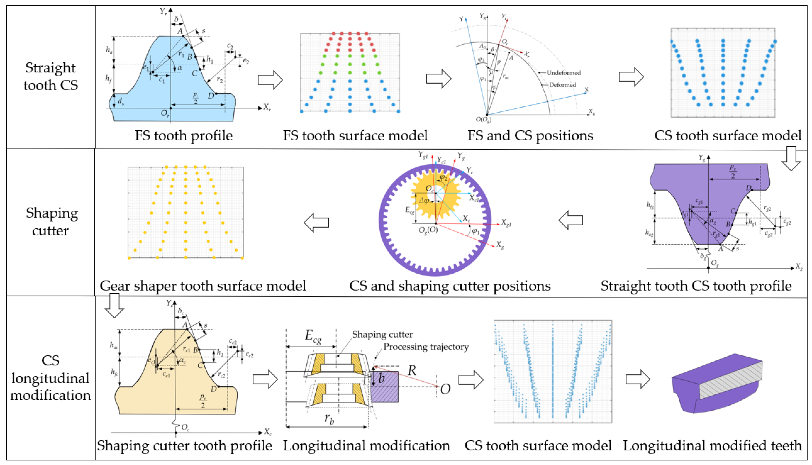
2. Tooth Longitudinal Modification for CS with DCTP

The generating processes for tooth longitudinal modification in CS with DTCP and the shaping cutter are depicted in Figure 2. This main process can be segmented into three distinct parts: straight tooth CS modeling, shaping cutter tooth profile modeling, and longitudinal modification of CS modeling. Firstly, by considering the conjugate relationship between the CS and the FS with DTCP, a mathematical model for the straight CS tooth is established based on the neutral layer and envelope conjugation theories. Subsequently, a shaping cutter capable of generating the straight CS tooth is derived through coordinate transformation and meshing principles. Lastly, longitudinal modification of the CS tooth is accomplished by adjusting the center of the shaping cutter relative to the CS center for arc motion.

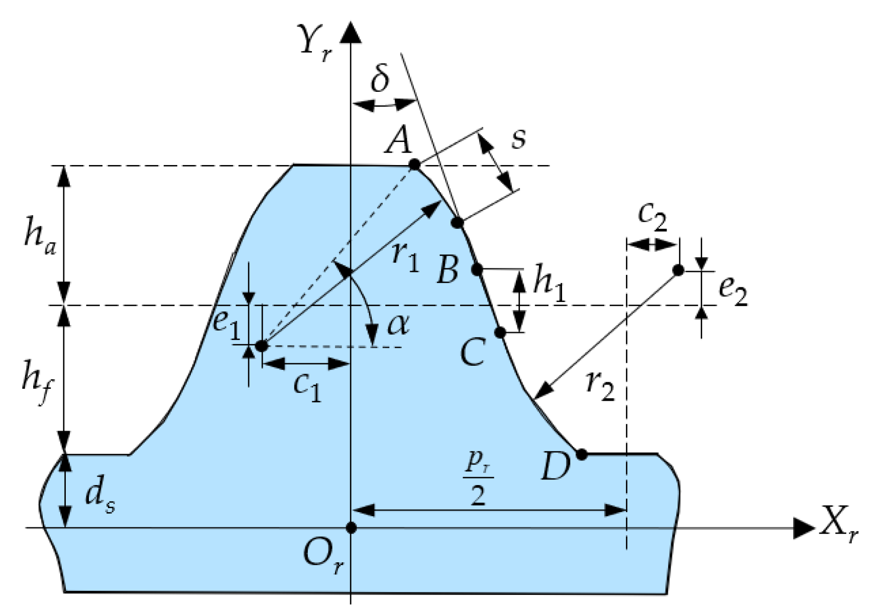
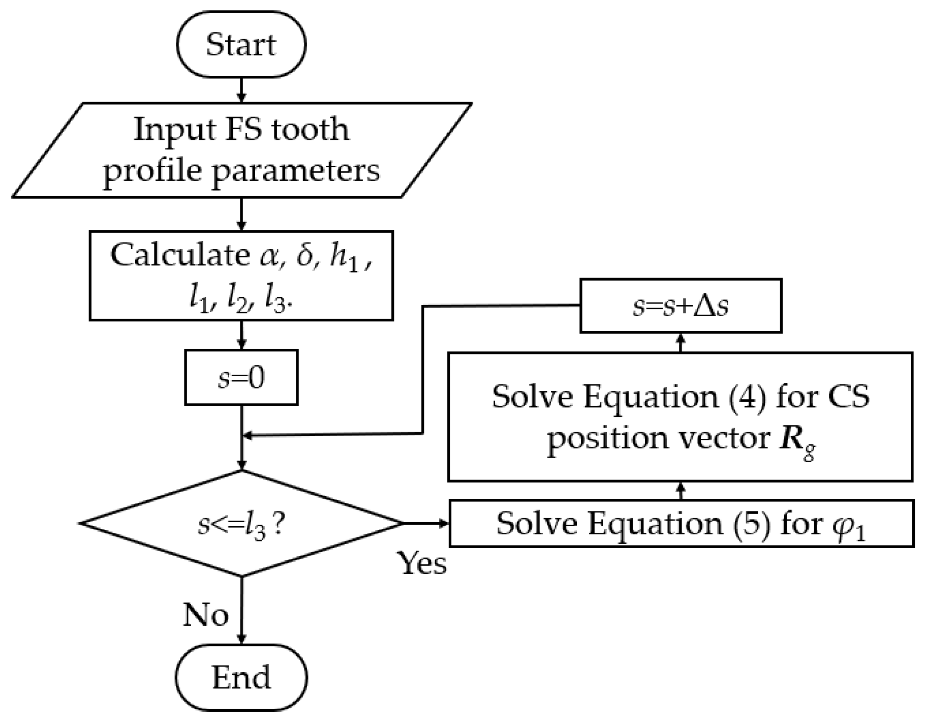
2.1. Straight Tooth CS

As shown in Figure 3, the DTCP is illustrated within the FS local coordinate system. The origin Or is defined as the intersection point of the neutral layer of the FS and the symmetry axis of the gear teeth. A local coordinate system Sr(Or, Xr, Yr) for the FS is then established, rigidly connected to the FS gear teeth. Segment AB represents a convex arc tooth profile, segment BC represents a straight segment tooth profile, and segment CD represents a concave arc tooth profile. The parameter definitions of the DTCP are shown in Table 1.
From Figure 3, it can be seen that s denotes the arc length from any point on the tooth profile to point A. The piecewise functions of the convex tooth profile, straight tooth profile, and concave tooth profile of the DCTP are as follows:
The position vector for segment AB of the convex arc tooth profile in coordinate system Sr is determined with the following equation:
R r 1 ( s ) = x r 1 y r 1 1 = r 1 cos ( α s r 1 ) c 1 r 1 sin ( α s r 1 ) + h f + d s e 1 1 , s ( 0 , l 1 )
where r1 is the convex arc radius, α is the tooth tip pressure angle, c1 and e1 are the center displacement of the convex arc in the Xr and Yr directions, respectively, hf is the dedendum, and ds is half of the wall thickness of the FS.
The position vector for segment BC of the linear tooth profile in coordinate system Sr is determined with the following equation:
R r 2 ( s ) = x r 2 y r 2 1 = r 1 cos δ c 1 + ( s l 1 ) sin δ r 1 sin δ + h f + d s e 1 ( s l 1 ) cos δ 1 , s ( l 1 , l 2 )
where l1 is the length of the convex tooth profile, l2 is the length of the straight tooth profile, and δ is the common tangent inclination angle.
The position vector for segment CD of the concave arc tooth profile in coordinate system Sr is determined with the following equation:
R r 3 ( s ) = x r 3 y r 3 1 = r 1 cos ( δ + s l 2 r 2 ) + p 2 + c 2 r 2 sin ( δ + s l 2 r 2 ) + h f + d s + e 2 1 , s ( l 2 , l 3 )
where l3 is the length of the concave tooth profile, p is the tooth pitch, and r2 is the concave arc radius.
Coordinate systems applied for the derivation of the CS tooth surface mathematical model are shown in Figure 4. The local coordinate systems S(O, X, Y) and the global Sg(Og, Xg, Yg) are fixed on the WG and CS, respectively. The origin O of the coordinate system S is positioned at the rotation center of the HD. The Y-axis and the X-axis point to the long-axis and short-axis direction of the WG, respectively, and rotate with the WG. Sg is a global coordinate system, and its origin, Og, is also positioned at the rotation center of the HD, with Yg located on the angle bisector of the CS teeth. Assuming that point A0 is a point on the undeformed neutral layer, A0 will move to point A when the FS rotates through an angle φ1 without considering deformation. However, due to the WG deforming the FS, the position of point A changes to point Or. Additionally, ρ is the length between the point Or and the point Og, rm is the radius of the neutral circle of the FS, μ is the normal angle formed by the deformation of the FS, φ2 is the rotation angle of the WG, φ is the angle between the undeformed end of the FS and Yg, and β is the angle between the axes Yg and Yr.
Based on the coordinate transformation depicted in Figure 4, the position vector of the CS tooth surface can be expressed in the coordinate system Sg and can be determined by the following equations:
R g ( φ 1 , s ) = M g r R r ( s )
f ( φ 1 , s ) = ( R g s × 0 0 1 ) · R g φ 1 = 0
where Equation (5) is the meshing equation between the CS and FS, and
M g r = cos β sin β ρ sin φ 1 sin β cos β ρ cos φ 1 0 0 1 .
Parameter β can be solved using the following approach based on the neutral layer concept.
The cosine cam acts as a WG, and its outer contour is in the shape of an elliptical line. After assembling it with the FS, the neutral layer of the FS will deform similarly to the outer contour of the WG. Therefore, the deformed neutral layer equation is as follows:
ρ = r m + w 0 cos ( 2 φ 3 )
where φ3 is the relative rotation angle between WG and FS, and φ3 = φ1 + φ2.
From Figure 3, it can be observed that:
β = φ 1 + μ
The transmission ratio of the harmonic reducer can be expressed as:
φ 2 = Z r Z g Z r φ
According to Ref. [12], normal rotation angle μ, radial deformation ω, circumferential deformation v, and rotational angle φ1 can be derived by the neutral layer concept as follows:
μ = arctan ( ρ ρ )
ω = ρ r m
ν = 0 φ + φ 2 ω d φ 3
φ 1 = φ + ν r m
Combining Equations (7)–(10), parameter β can be solved.
As Equation (4) involves two unknown variables, the tooth profile variable s and the rotation angle φ1, a stepwise iterative method is employed for its solution. The calculation process is illustrated in Figure 5. Initially, compute the discrete s value based on the input parameters and solve the meshing equation Equation (5) to derive the corresponding φ1 value. Subsequently, substitute the determined s value and φ1 value into the CS coordinate equation to obtain the corresponding position vector Rg.
Curve fitting is performed on the discrete tooth profile points to derive the analytical equation of the straight tooth profile. Figure 6 illustrates the local coordinate system of a straight tooth in the CS. Based on the arc radius and circle center obtained from the arc fitting of the straight tooth CS profile, curve fitting is conducted to obtain the analytical equation for the straight tooth CS profile. The parameter definitions of the CS profile are shown in Table 2.
The position vector Rg1, after curve fitting of the concave tooth profile of the CS, is expressed as follows:
R g 1 = X g 1 Y g 1 1 = r g 1 cos ( α g s r g 1 ) c g 1 r g 1 sin ( α g s r g 1 ) + e g 1 + r g 1 , s ( 0 , l g 1 )
where rg is the CS indexing circle radius, rg1 is the convex arc radius of the CS, lg1 is the length of the convex tooth profile of the CS, αg is the tooth tip pressure angle of the CS, cg1 and eg1 are the center displacement of the convex arc in the Xg and Yg directions, respectively, and s serves as a variable representing the profile function of the CS.
The position vector Rg2, after curve fitting of the straight tooth profile of the CS, is expressed as follows:
R g 2 = X g 2 Y g 2 1 = r g 1 cos δ g c g 1 + ( s l g 1 ) sin δ g r g 1 sin ( δ g ) e g 1 ( s l g 1 ) cos δ g + r g 1 , s ( l g 1 , l g 2 )
where lg2 is the length of the straight tooth profile, and δg is the common tangent inclination angle of the CS.
The position vector Rg3, after curve fitting of the convex tooth profile of the CS, is expressed as follows:
R g 3 = X g 3 Y g 3 1 = r g 2 cos ( δ g + s l g 2 r g 2 ) + p g 2 + c g 2 r g 2 sin ( δ g + s l g 2 r g 2 ) e g 2 + r g 1 , s ( l g 2 , l g 3 )
where lg3 is the length of the concave tooth profile, pg is the tooth pitch of CS, rg2 is the concave arc radius, and cg2 and eg2 are the center displacement of the concave arc in the Xg and Yg directions, respectively, of the CS.

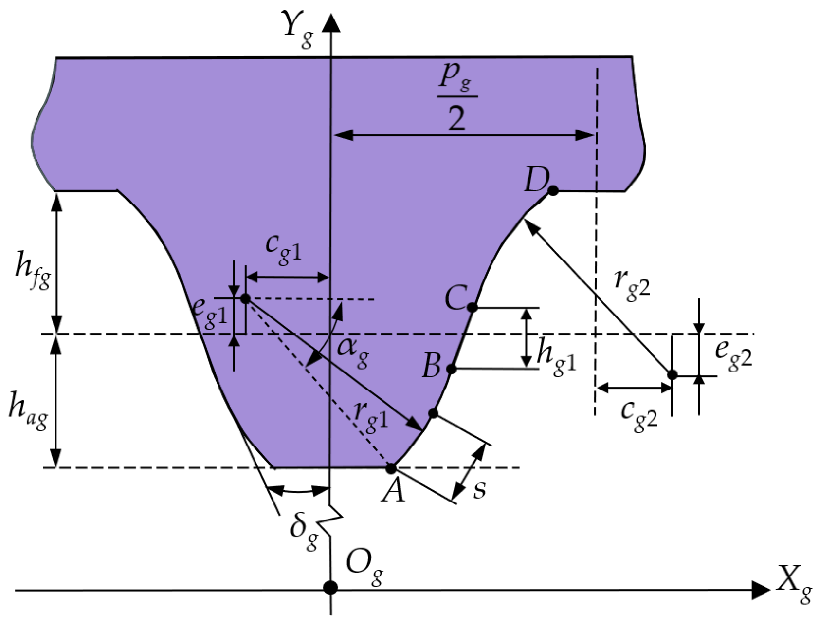
2.2. Shaping Cutter Tooth Profile

As shown in Figure 7, the processing coordinate system of the shaping cutter for machining the CS is illustrated. The local coordinate systems Sc1(Oc1, Xc1, Yc1) and Sg1(Og1, Xg1, Yg1) are attached to the shaping cutter and the CS, respectively. Additionally, Yg1 is located on the angle bisector of CS teeth, and Yc1 is located on the angle bisector of shaping cutter teeth. Oc represents the center of the shaping cutter, while Og denotes the center of the CS. In addition, φ1 and φ2 are the rotation angles of the CS and the shaping cutter, respectively, and Ecg is the center distance between the shaping cutter and the CS. Δφ is the angle between Yg1 and Yc1, and Δφ is half of the central angle between two adjacent teeth of the CS.
Based on the processing coordinate transformation depicted in Figure 7, the position vector of the shaping cutter tooth surface can be expressed in the coordinate system Sg1 can be determined by the following equations:
R c ( s , φ 1 ) = M c c 1 M c 1 g 1 M g 1 g R g ( s )
f ( φ 1 , s ) = ( R c s × 0 0 1 ) · R c φ 1 = 0
where M g 1 g = cos φ 1 sin φ 1 0 sin φ 1 cos φ 1 0 0 0 1 , M c 1 g 1 = cos φ sin φ 0 sin φ cos φ E c g 0 0 1 , M c c 1 = cos φ 2 sin φ 2 0 sin φ 2 cos φ 2 0 0 0 1 , φ1 is the rotation angle of the CS, and φ2 is the rotation angle of the shaping cutter.
The relationship between angles φ1 and φ2 satisfies the following equation:
φ 1 φ 2 = Z c Z g
where Zc and Zg represent the tooth number of the shaping cutter and the CS, respectively.
Curve fitting is conducted on the discrete tooth profile points to derive the analytical equation of the shaping cutter tooth profile. Figure 8 illustrates the curve fitting of discrete tooth profile points to obtain the shaping cutter tooth profile curve, followed by fitting the shaping cutter tooth profile curve into the tooth profile analytical equation.
The position vector Rc1, after curve fitting of the convex tooth profile of the shaping cutter, is as follows:
R c 1 = x c 1 y c 1 1 = r c 1 cos ( α c s r c 1 ) c c 1 r c 1 sin ( α c s r c 1 ) e c 1 + r c 1 , s ( 0 , l c 1 )
where rc is the shaping cutter indexing circle radius, lc1 is the length of the convex tooth profile of the shaping cutter, rc1 is the convex arc radius of the shaping cutter, αc is the tooth tip pressure angle of the shaping cutter, and cc1 and ec1 are the center displacement of the convex arc in the Xc and Yc directions, respectively, of the shaping cutter.
The position vector Rc2, after curve fitting of the straight tooth profile of the shaping cutter, is as follows:
R c 2 = x c 2 y c 2 1 = r c 1 cos δ c c c 1 + ( s l c 1 ) sin δ c r c 1 sin ( δ c ) e c 1 ( s l c 1 ) cos δ c + r c 1 , s ( l c 1 , l c 2 )
where lc2 is the length of the straight tooth profile of the shaping cutter, and δc is the common tangent inclination angle.
The position vector Rc2, after curve fitting of the concave tooth profile of the shaping cutter, is as follows:
R c 3 = x c 3 y c 3 1 = r c 1 cos ( δ + s l c 2 r c 2 ) + p c 2 + c c 2 r c 2 sin ( δ + s l c 2 r c 2 ) + e c 2 + r c 1 , s ( l c 2 , l c 3 )
where lc3 is the length of the concave tooth profile of the shaping cutter, pc is the tooth pitch of the shaping cutter, rc2 is the concave arc radius of the shaping cutter, and cc2 and ec2 are the center displacement of the concave arc in Xc and Yc directions, respectively, of the shaping cutter.

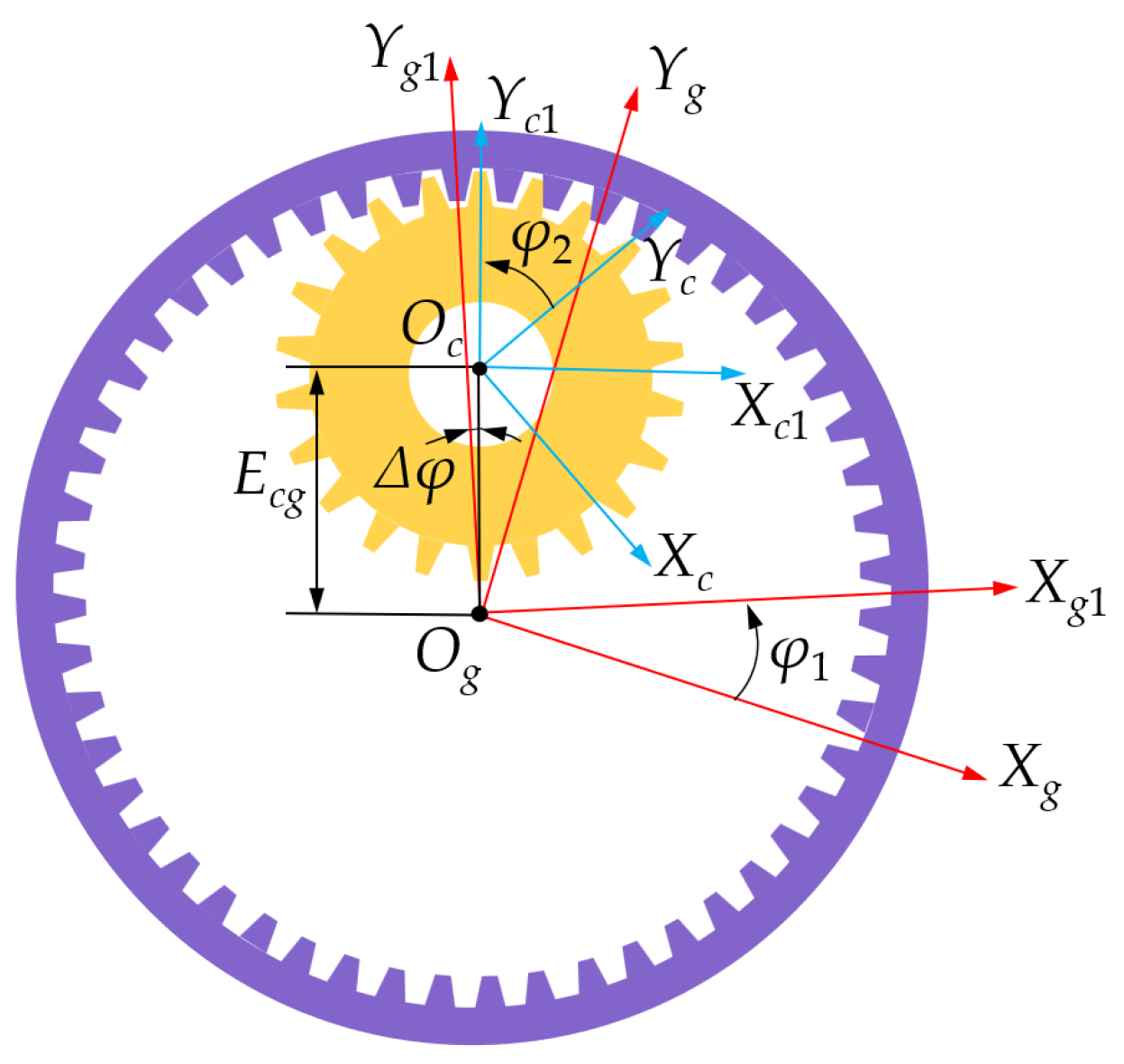
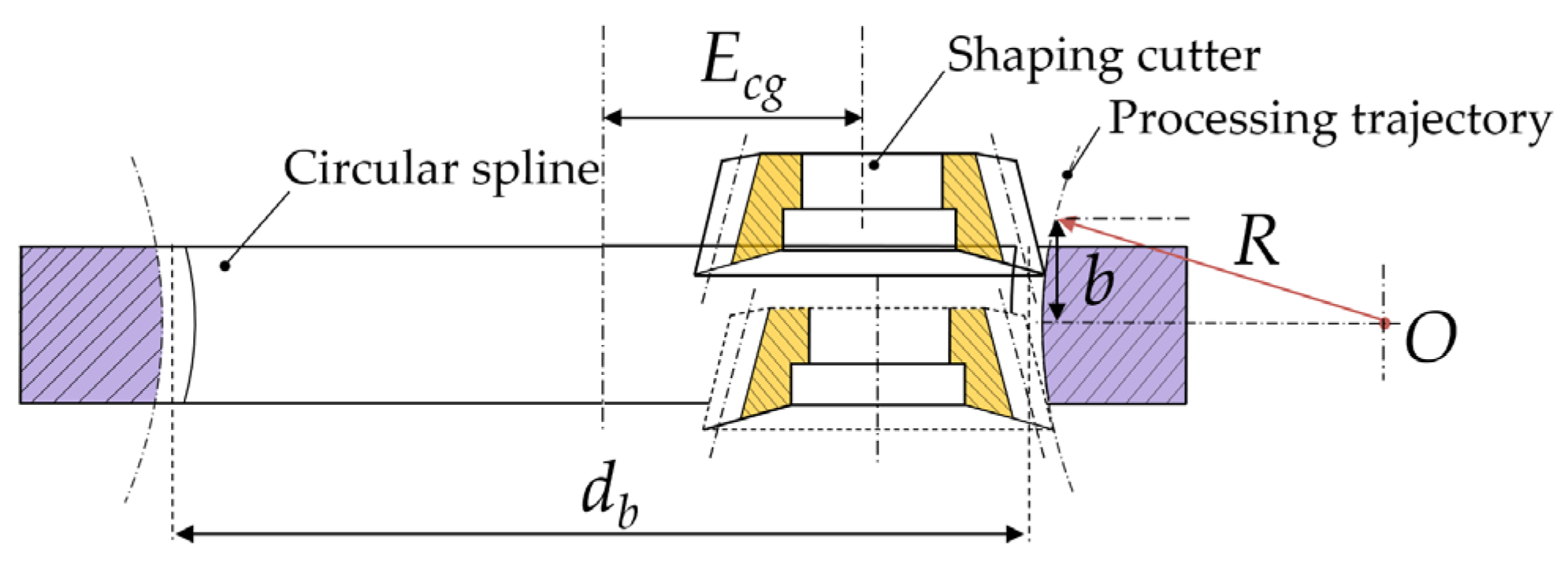
2.3. Longitudinal Modification of CS

The longitudinal modification of the CS tooth can be achieved by adjusting the center of the shaping cutter relative to the CS center for arc motion, as shown in Figure 9. From Figure 9, it can be observed that the arc motion can be accomplished by changing the center distance Ecg between the CS and the shaping cutter. In addition, point O is the center of the arc motion trajectory, R is the longitudinal modification radius, b is the distance from the shaping cutter cutting point to the centerline of the CS tooth width, and db is the pitch diameter of the CS.
The center distance Ecg between the CS and the shaping cutter can be represented as follows:
E cg = m ( Z g Z c ) 2 R 2 b 2 + R
According to the processing coordinate system of the shaping cutter for machining the CS shown in Figure 7, any tooth profile equation along the tooth width cross-section can be represented as:
R g ( s , φ 1 ) = M g g 1 M g 1 c 1 M c 1 c R c ( s )
f ( φ 1 , s ) = ( R g s × 0 0 1 ) · R g φ 1 = 0
where
M g g 1 = cos φ 1 sin φ 1 0 sin φ 1 cos φ 1 0 0 0 1 ,   M g 1 c 1 = cos φ sin φ E c g sin φ sin φ cos φ E c g cos φ 0 0 1 ,   M c c = cos φ 2 sin φ 2 0 sin φ 2 cos φ 2 0 0 0 1 .
Providing a value for b, Equation (22) can be used to determine the center distance Ecg. Then, by substituting Ecg into Equations (23) and (24), the tooth profile can be established with the distance from the shaping cutter cutting point to the centerline of the CS tooth width set as b. Continuously adjusting the value of b allows for the creation of a three-dimensional tooth surface model of the CS with longitudinal modification.

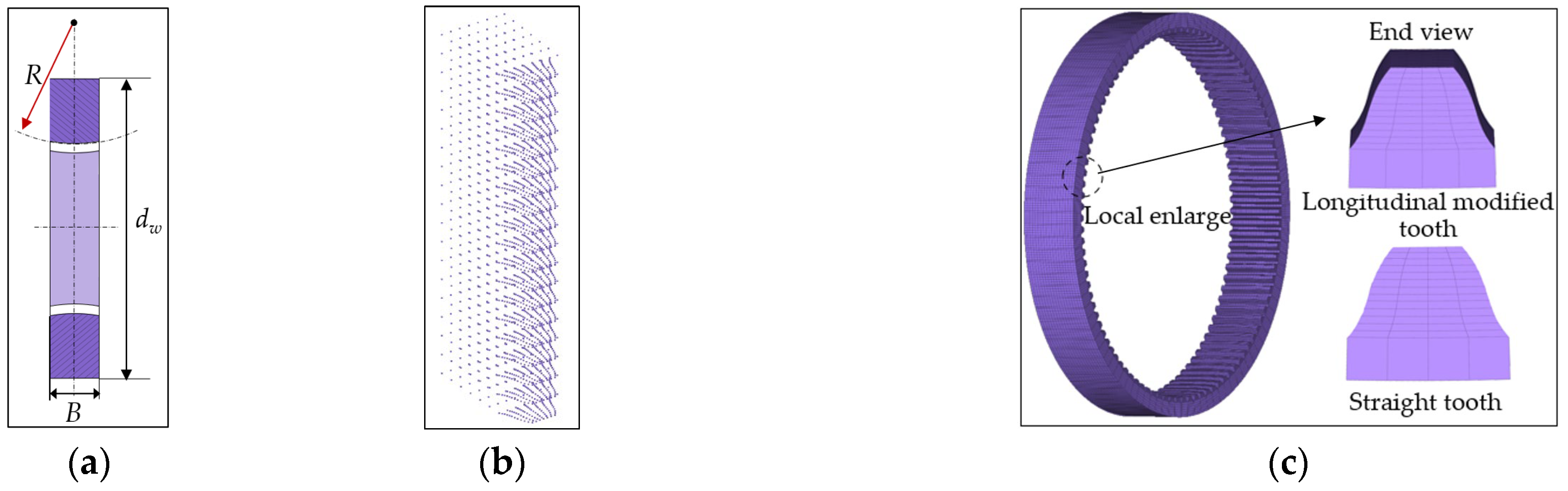
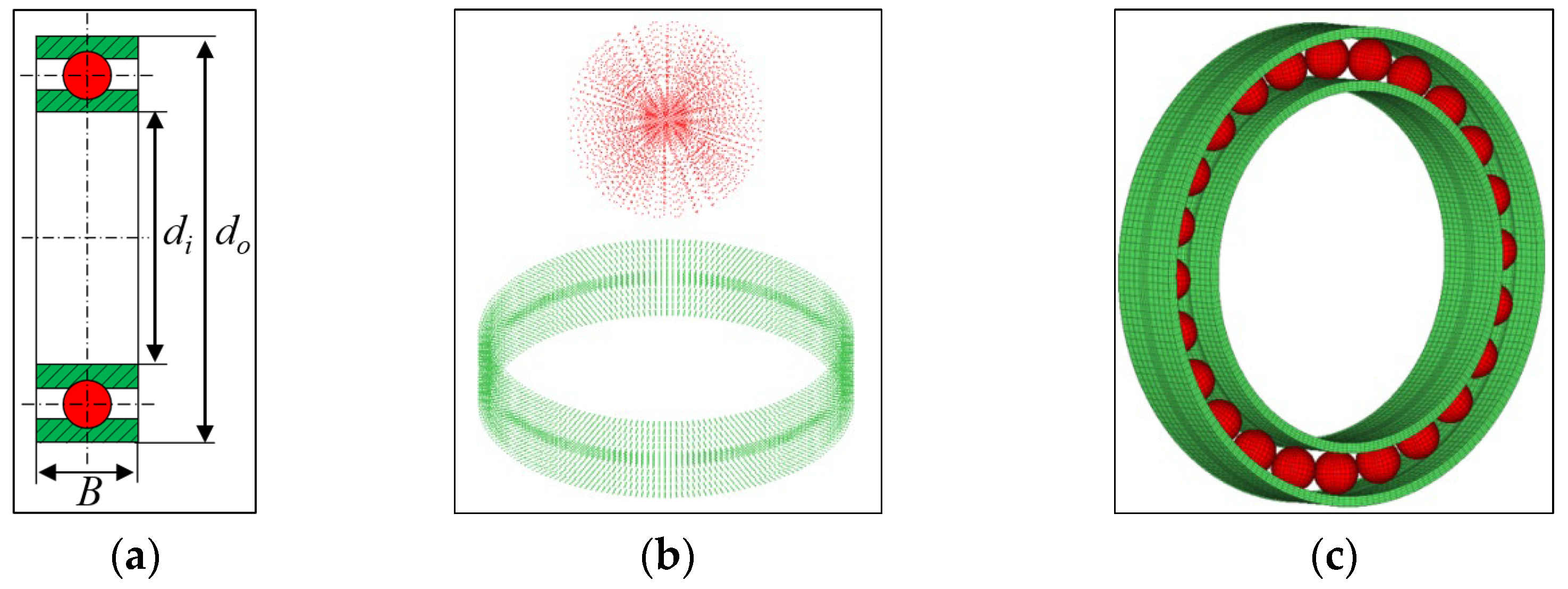
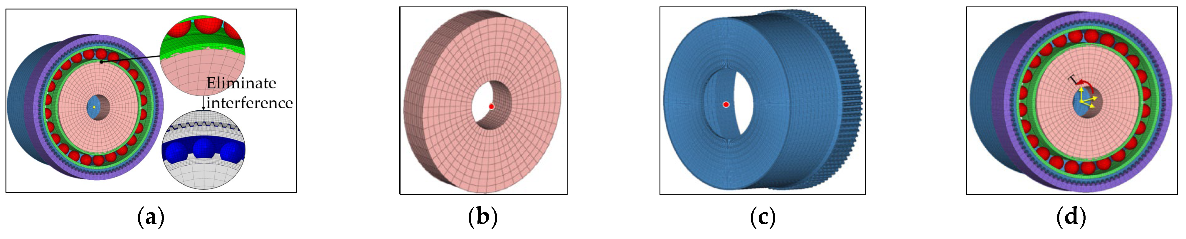
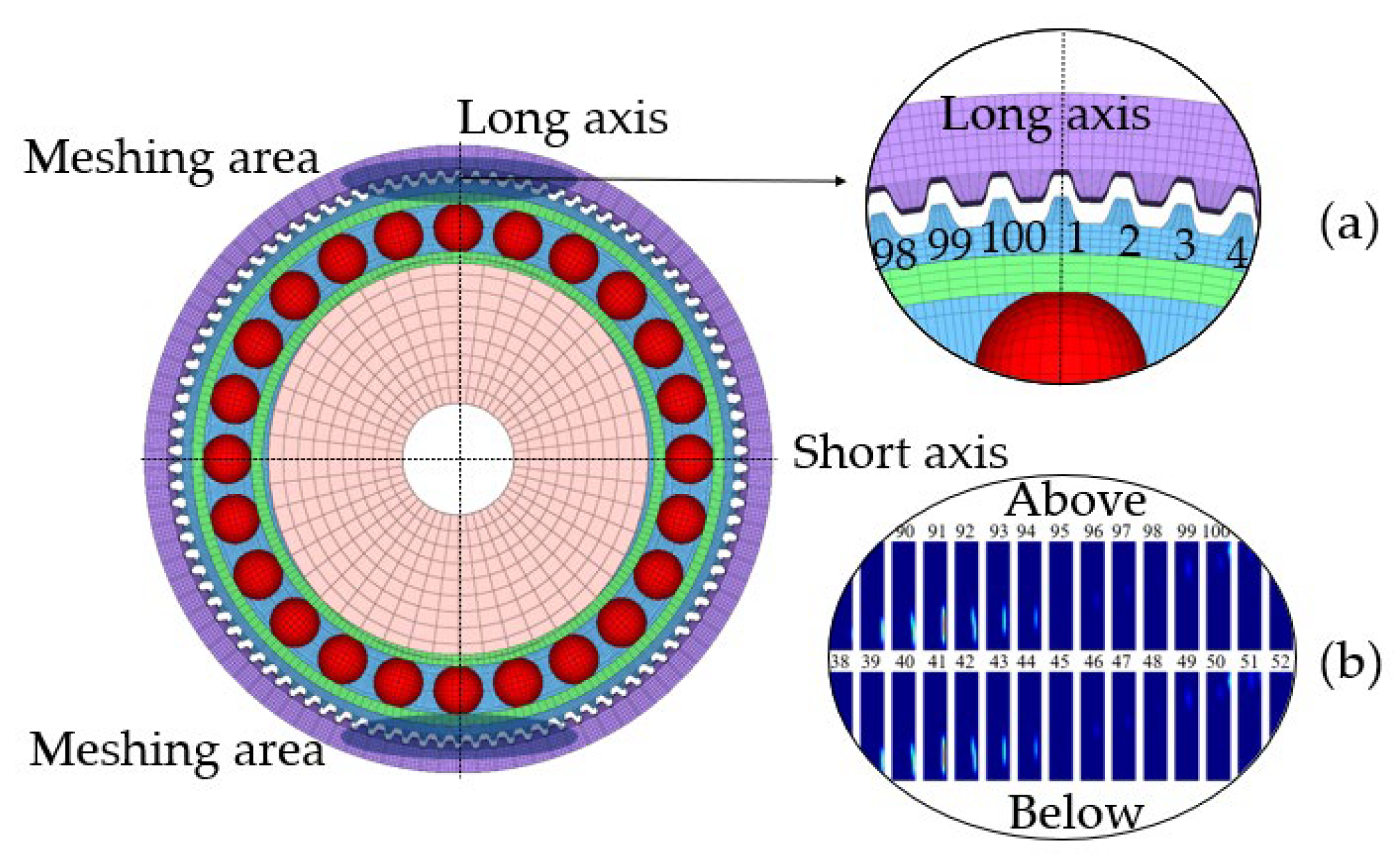
3. Parametric Finite Element Model of HDs

An HD always consists of four main components: FS, CS, flexible bearing (FB), and WG. The accuracy of finite element mesh modeling and assembly of the aforementioned main components determines the precision of contact analysis. Hence, utilizing the discrete nodes generated by the parametric model, a precise finite element model is constructed for the HD with the longitudinally modified tooth CS. Parametric modeling of the HD is conducted using MATLAB 2016a. Because the geometric mathematical models of FS and CS tooth surfaces are very complex, it is difficult to directly establish a solid model in the form of equations and divide the mesh in 3D modeling analysis software such as ABAQUS 2022. Moreover, the accuracy of shape modeling has a significant impact on contact solutions, and approximate modeling methods cannot be used. Only discrete methods can be used to form point clouds and establish high precision tooth surface models. The advantage of MATLAB is that it can achieve a high precision point cloud solution of tooth surfaces, establish high precision tooth surface models, and use spatial coordinate changes to achieve high precision assembly between various components. It can also be parameterized. Initially, the entire model is discretized into spatial points, which are then interconnected point by point to create the hexahedral finite element model. Subsequently, the material properties, element attributes, assembly relationships, and boundary conditions of each part are documented in the INP file, which is then imported into ABAQUS for further calculation.
The structural diagram, single tooth nodes, and finite element model of the FS are shown in Figure 10a–c, separately. From Figure 10a, it can be observed that L is the FS length, B is the tooth width, rf is the inner diameter of FS, dst is the wall thickness, rk is the Inner diameter of FS bottom, and Ld is the thickness of the bottom wall of the FS.
The structural diagram, single tooth nodes, and finite element model of the CS are shown in Figure 11a–c, respectively. From Figure 11a, it can be observed that R is the modification radius, and dw is the rim diameter of the CS. In Figure 11c, the small image on the right shows end view diagrams of the CS longitudinal modification profile and straight profile.
The structural diagram, ball and ring nodes, and finite element model of the FB are shown in Figure 12a–c, respectively. From Figure 12a, it can be observed that di and do are the inner and outer diameters, respectively.
The structural diagram, WG nodes, and finite element model of the WG are shown in Figure 13a–c, respectively. From Figure 13a, it can be observed that a and b are the short axis length and the long axis length, respectively. The distance from a point on the WG to the center of the WG can be represented as:
ρ wg = d i 2 + ε cos ( 2 φ )
where ε is the WG profile coefficient.
During the discretization of the computational model, 8-node 3D solid elements (C3D8R) were used, as they provide a good balance between computational efficiency and accuracy. Furthermore, to ensure precise contact simulation, the Penalty contact algorithm in Abaqus was employed, which enables more accurate contact simulation without increasing model stiffness. Additionally, a friction coefficient was applied to the contact surfaces, set according to the relative motion between the FS and CS to closely mimic real working conditions. For all other contact pairs, a surface-to-surface contact was adopted, with a friction coefficient of 0.08 between the rollers and outer race, and 0.15 for the remaining contact pairs.
The accuracy of the simulation analysis still heavily relies on the boundary conditions imposed on the model. The simulation process is divided into three distinct load steps, each building upon the previous one. Initially, constraints are imposed on the FS displacement along its long axis, while contact is established between the FB and WG, as well as between the FB and FS. This initial step aims to eliminate interference between the FB and WG, illustrated in Figure 14a. The subsequent step focuses on establishing tooth contact between the CS and FS without applying any loads. This is accomplished by fully constraining the CS, WG, and FS through coupling points, as depicted in Figure 14b,c. In the final step, the rotational freedom of the WG and FS along the axis direction is released. Additionally, torque is applied to the coupling point of the FS, as shown in Figure 14d.

4. Results and Discussion

To validate the effectiveness of the CS tooth longitudinal modification method proposed in this paper, a comparison of contact characteristics between modified and unmodified CS tooth profiles is conducted. Additionally, to assess its contact characteristics for HDs with a short FS, the impacts of FS length-to-diameter ratio, WG profile, modification radius, and torque on contact pressure and load sharing among teeth are also investigated. The basic parameters of FS and CS for analysis are listed in Table 3, and the material mechanics properties of parts of HD components are listed in Table 4.
The FS teeth are numbered in the clockwise direction, which starts from the upper tooth, as shown in Figure 15a. From Table 1, it is observed that the FS and CS have 100 and 102 teeth, respectively. Since the number of teeth is even, the two contacting surfaces with a relative angular spacing of 180° between FS teeth exhibit identical contact states, as depicted in Figure 15b. Moreover, the FS teeth’s contact area is situated near the long axis. Therefore, due to the large number of teeth, it is impractical to display the contact status of every tooth’s working surface in the contact distribution diagram. Instead, this paper solely illustrates the contact status of FS teeth near the lower end of the long axis.

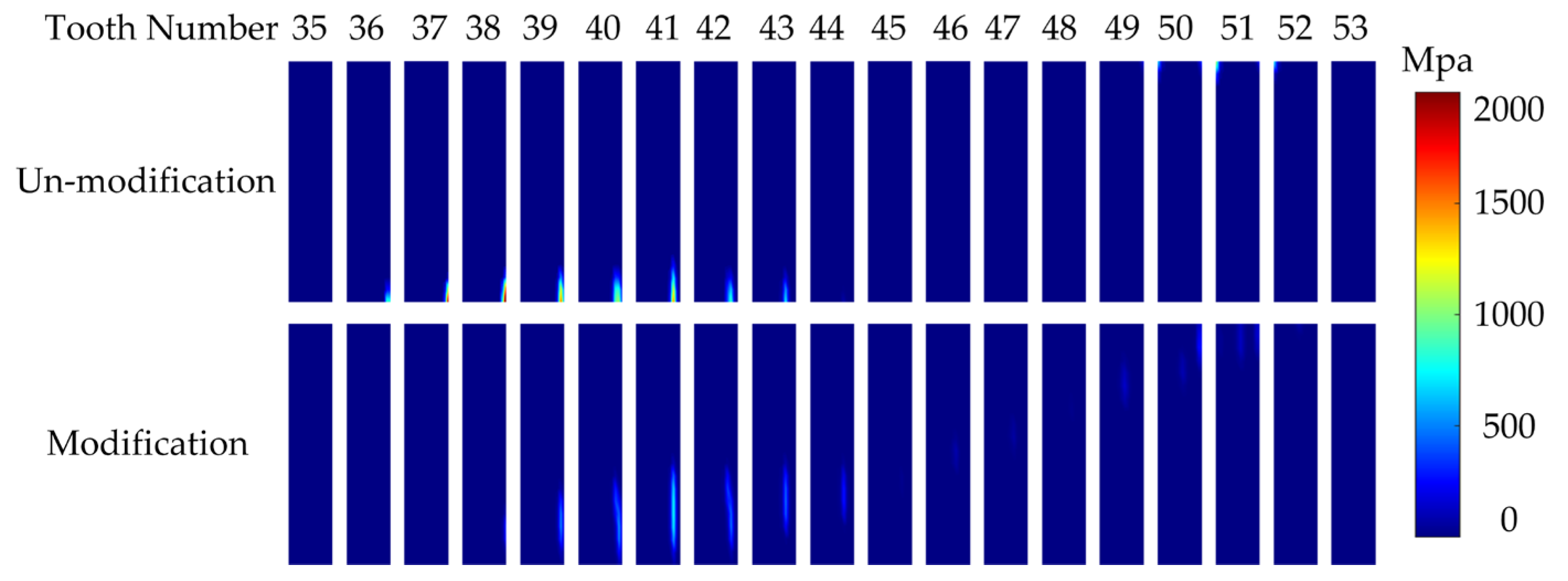
4.1. Comparison Between CS Teeth with and Without Longitudinal Modification

In order to verify the effectiveness of the proposed method, two sets of examples, with and without modification radius R = 200 mm, are selected for analysis. The analysis results are shown in Figure 16 and Figure 17.
Figure 16 illustrates a comparison of the contact pressure between CS teeth with and without modification. When the CS teeth are unmodified longitudinally, as depicted in Figure 16, it is evident that contact areas are predominantly concentrated near the tooth end, with the maximum contact pressure peaking at 2649 MPa, indicating severe stress concentration. It can be observed from Figure 16 that when the cylinder length is relatively short and without modification, there is indeed stress concentration in the meshing of the gear teeth, consistent with the findings in references [10,30], further validating the rationality of the model. Conversely, with a modification radius of R = 200 mm, the contact area expands and shifts from the tooth end toward the middle along the width of the tooth. Consequently, the maximum contact pressure notably decreases to 804 MPa, representing a significant reduction of 69.6%. Therefore, longitudinal modification of CS teeth effectively increases the contact area and avoids stress concentration. By comparing the contact stress analysis results between CS teeth with and without modification in this study, it is evident that the longitudinal modification of CS teeth effectively addresses the issues of edge contact and stress concentration in HDs with short FS. This verifies the superiority of the proposed method over traditional approaches.
Figure 17 depicts the load sharing among teeth for CS teeth with and without modification. From Figure 17, it can be seen that the number of engaged teeth is 13, and the tooth carrying the heaviest load is #41 near the lower end of the long axis, regardless of modification. Therefore, the appropriate amount of CS tooth longitudinal modification hardly alters the load sharing among teeth.

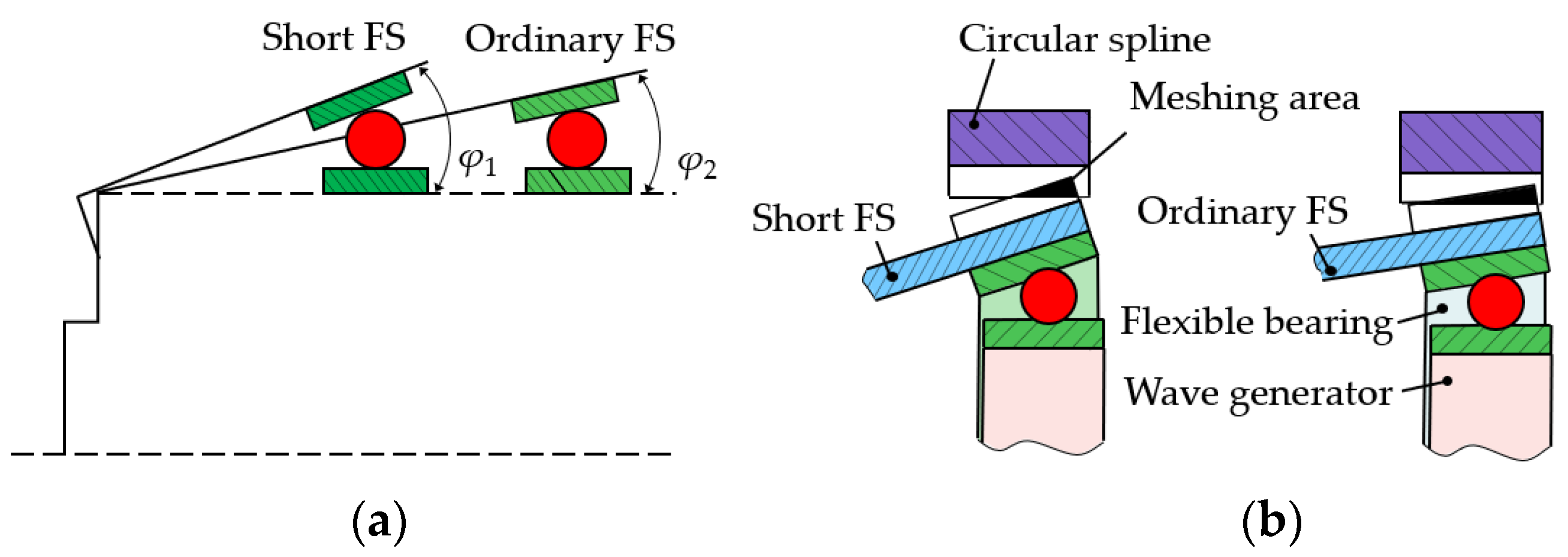
4.2. Effect of FS Length-to-Diameter Ratio on Contact Pressure and Load Sharing

A compact design is achieved with a short FS, characterized by an FS length-to-diameter ratio (Q) of less than 0.5. To investigate the impact of FS length on tooth surface contact pressure and load sharing among teeth, five sets of different Q values (Q = 0.2, 0.4, 0.6, 0.8, and 8) are selected for contact analysis under two conditions: CS teeth with and without longitudinal modification.
(1)
CS teeth without longitudinal modification
The results of the analysis are presented in Figure 18 and Figure 19, illustrating the variations in contact pressure and load sharing across teeth corresponding to different Q values when the CS teeth are without longitudinal modification.
As shown in Figure 18, the maximum contact pressure follows a sequence of 4496 MPa, 2649 MPa, 2261 MPa, 1417 MPa, and 568 MPa as Q gradually increases from 0.2 to 8. And, it is evident that the contact area shifts from the tooth end to the middle of the tooth width, resulting in a gradual decrease in contact pressure and an increase in contact area. When Q reaches 8.0, the contact area spans the entire tooth surface along the tooth width. This phenomenon arises due to nearly axial uniform deformation of the FS when the length significantly exceeds the diameter.
From Figure 19, it can be observed that the number of engaged teeth near the lower end of the long axis gradually changes as Q increases from 0.2 to 8, with values of 11, 13, 13, 13, and 8, respectively. Initially, as Q increases, the number of engaged teeth increases, reaching a peak before gradually decreasing. When Q reaches 8.0, the teeth carrying the load are from #40 to #47. However, when Q is 0.2, the teeth carrying the load are from #36 to #41 and from #48 to #53. Hence, with an increase in Q, load sharing becomes more continuous.
(2)
CS teeth with longitudinal modification
When the CS teeth are with longitudinal modification, the results of the analysis are presented in Figure 20 and Figure 21, illustrating the variations in contact pressure and load sharing across teeth corresponding to different Q values.
After modification, as illustrated in Figure 20, the maximum contact pressure follows a sequence of 1964 MPa, 804 MPa, 774 MPa, 752 MPa, and 806 MPa as Q gradually increases from 0.2 to 8. Compared with the maximum contact pressure in the non-modified case, as shown in Figure 18, modification results in a reduction of 56%, 70%, 66%, 47%, and 42% in maximum contact pressure, respectively. When Q is large, such as 8.0, the modification does not decrease the maximum contact pressure; instead, it increases. This occurs when Q is sufficiently large, causing the modification to change the line contact to point contact, resulting in a smaller contact area and higher contact pressure.
After modification, as shown in Figure 21, the number of engaged teeth near the lower end of the long axis gradually changes as Q increases from 0.2 to 8, with values of 11, 13, 13, 13, and 9, respectively. Comparing this with the non-modified case shown in Figure 21, it is evident that modification hardly affects the number of engaged teeth, and the tooth carrying the heaviest load remains #41 or near #41 regardless of Q. Additionally, modification results in the maximum load becoming closer as Q increases.

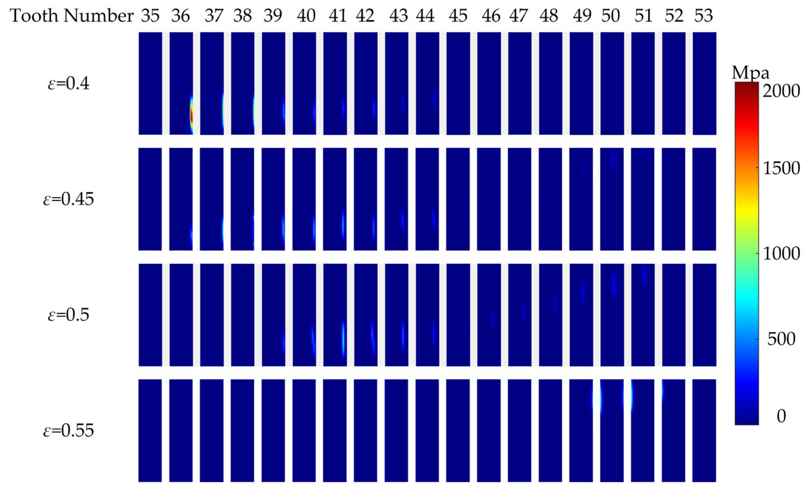
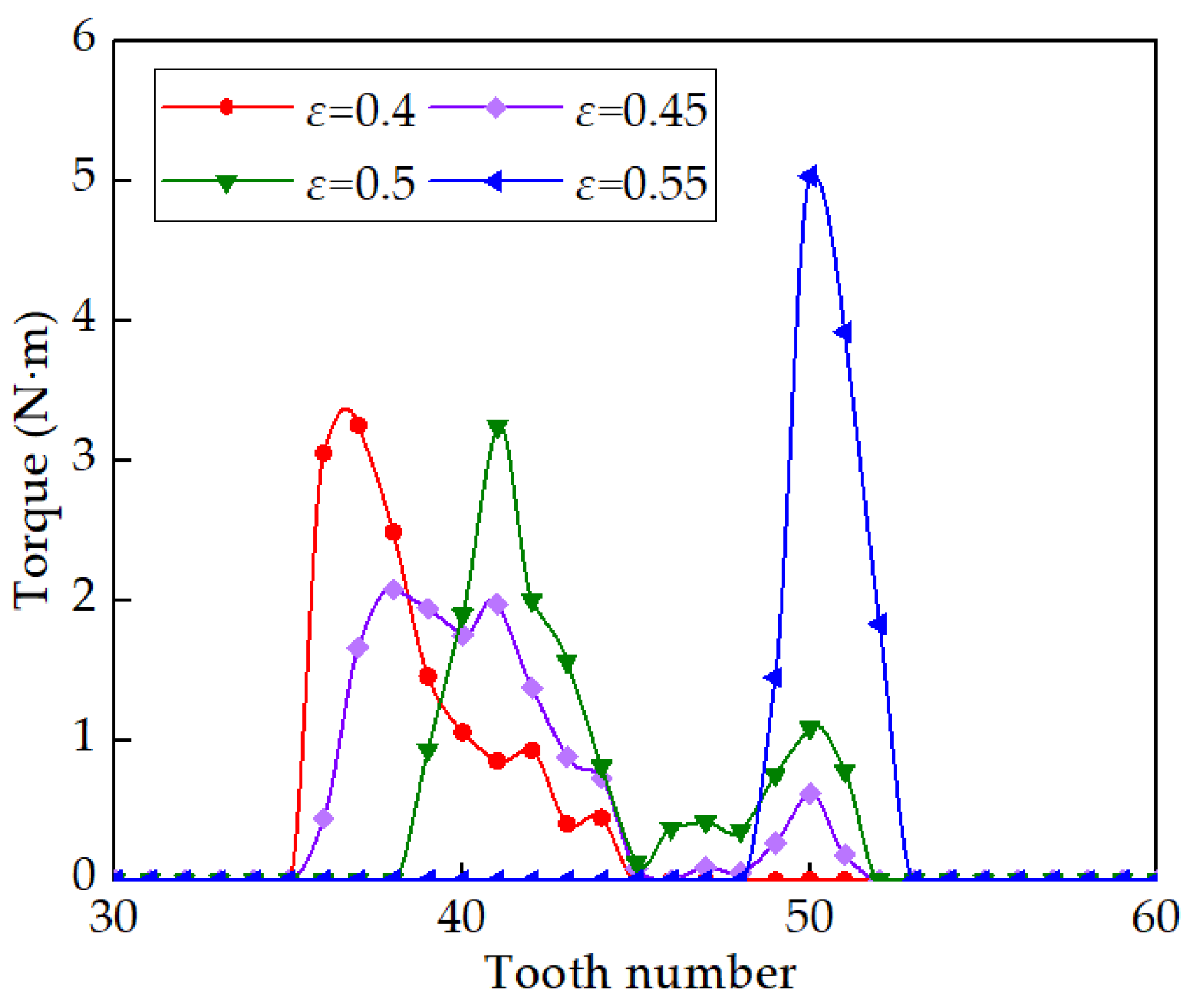
4.3. Effects of WG Profile on Contact Pressure and Load Sharing

The length of the long axis of WG directly determines the maximum height at which FS teeth are lifted, which significantly affects the meshing between the FS and CS. To analyze the influence of different profiles of WG on contact pressure and load sharing, four sets of WG profile coefficients (ε = 0.4, 0.45, 0.5, and 0.55) are selected for analysis. The analysis results are shown in Figure 22 and Figure 23.
Figure 22 illustrates the impact of ε on contact pressure. It is evident from Figure 22 that as the ε value gradually increases, the maximum contact pressure follows a sequence of 2187 MPa, 1283 MPa, 804 MPa, and 1001 MPa, respectively. Initially, with an increase in ε, the maximum contact pressure decreases before rising again. When ε deviates from ω0 (0.5), contact occurs at the FS tooth tip, leading to stress concentration. This is because the design and actual values of radial deformation are consistent when ε is 0.5.
Figure 23 illustrates the impact of ε on load sharing. It is evident from Figure 23 that as the ε value increases from 0.4 to 0.55, the number of engaged teeth near the lower end of the long axis gradually changes with values of 10, 14, 13, and 4, respectively. The tooth carrying the heaviest load follows a sequence of #37, #38, #41, and #50. This indicates that the variation in ε significantly alters the clearance distribution between adjacent gear teeth working surfaces, changes the positions of teeth carrying the heaviest load and the number of engaged teeth, and thus affects the load sharing among teeth.

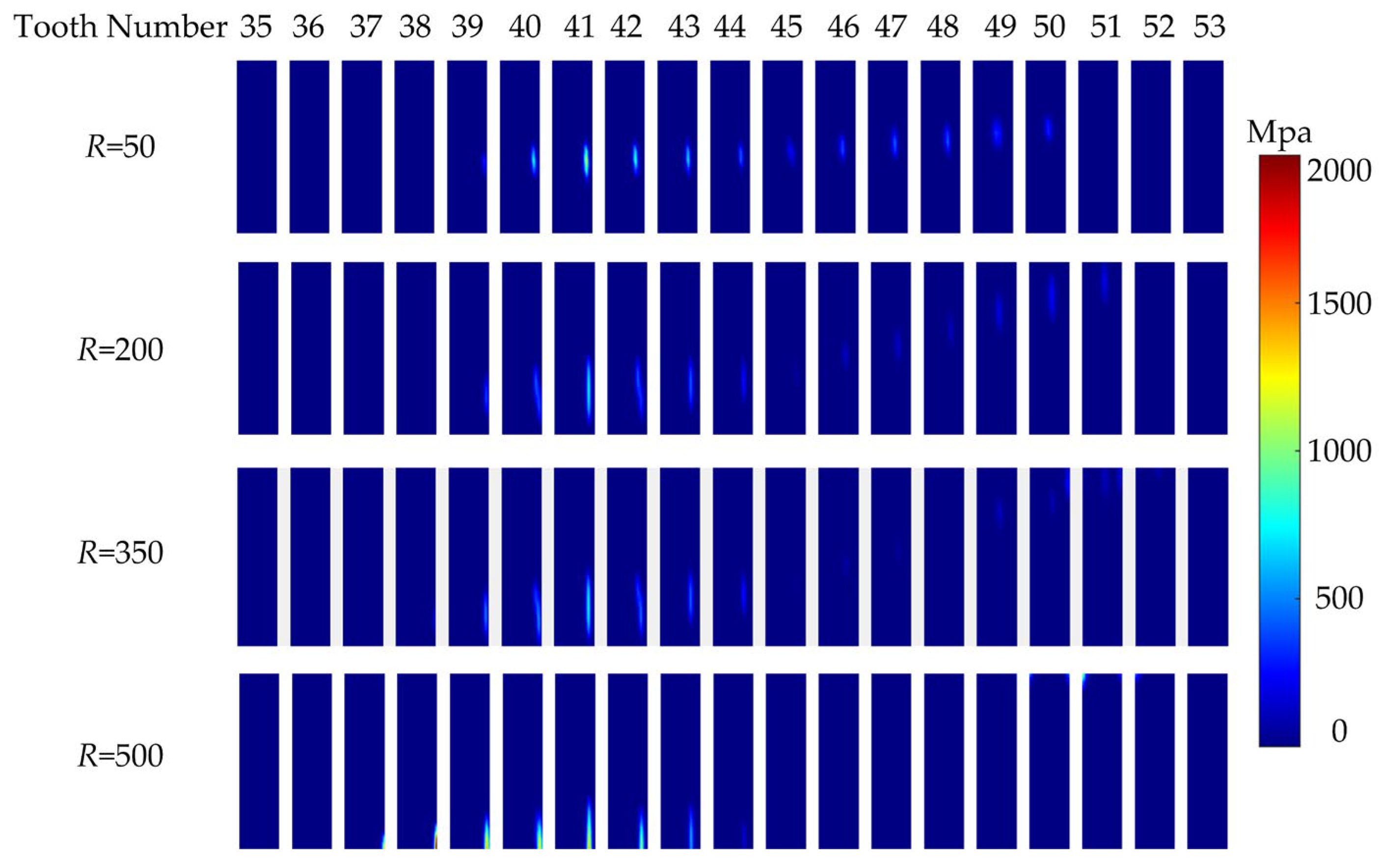
4.4. Effects of Modification Radius on Contact Pressure and Load Sharing

In order to gain deeper insights into the influence of modification radius on contact pressure and load sharing among teeth, the analysis encompasses four different modification radius (R = 50 mm, 200 mm, 350 mm, and 500 mm). The results of this analysis are presented in Figure 24 and Figure 25, illustrating the variations in contact pressure and load sharing among teeth corresponding to different modification radii.
From Figure 24, it is observed that as R gradually increases from 50 mm to 500 mm, the maximum contact pressure follows a sequence of 1238 MPa, 804 MPa, 1412 MPa, and 1991 MPa, respectively. The maximum contact pressure exhibits a trend of initially decreasing and then increasing. This phenomenon is primarily due to longitudinal modification shifting the contact position toward the middle of the tooth width, thereby avoiding edge contact and reducing contact stress. However, as the modification radius decreases, resulting in an increased modification amount, it also leads to a reduction in contact area, consequently increasing contact pressure.
In Figure 25, it is observed that as R increases incrementally from 50 mm to 500 mm, the number of engaged teeth near the lower end of the long axis follows a sequence of 12, 13, 13, and 13, respectively. Furthermore, regardless of the modification radius, tooth #41 consistently bears the heaviest load. Consequently, the modification radius has minimal influence on both the number of engaged teeth and the load sharing trend among teeth as the gear teeth’s position changes.

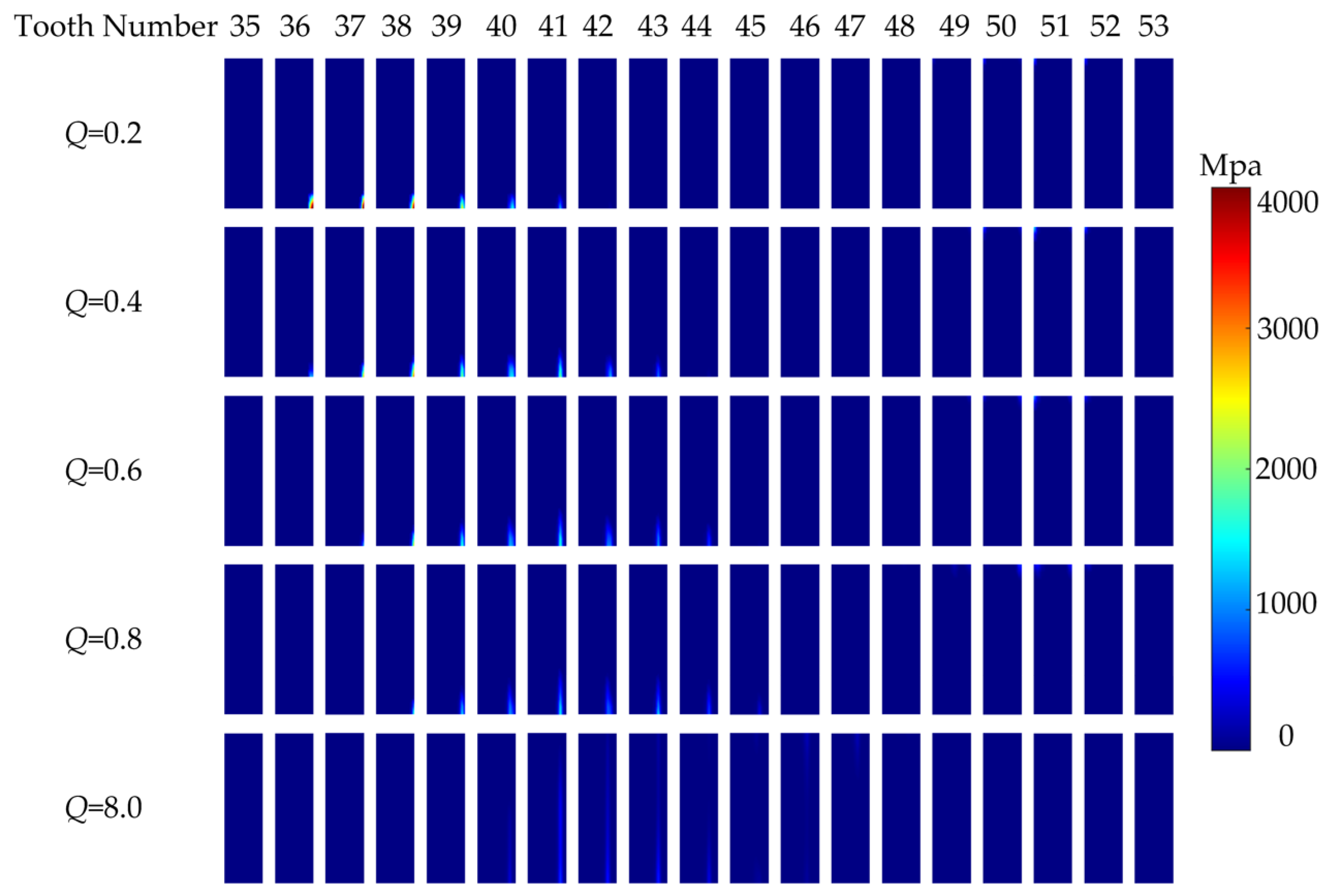
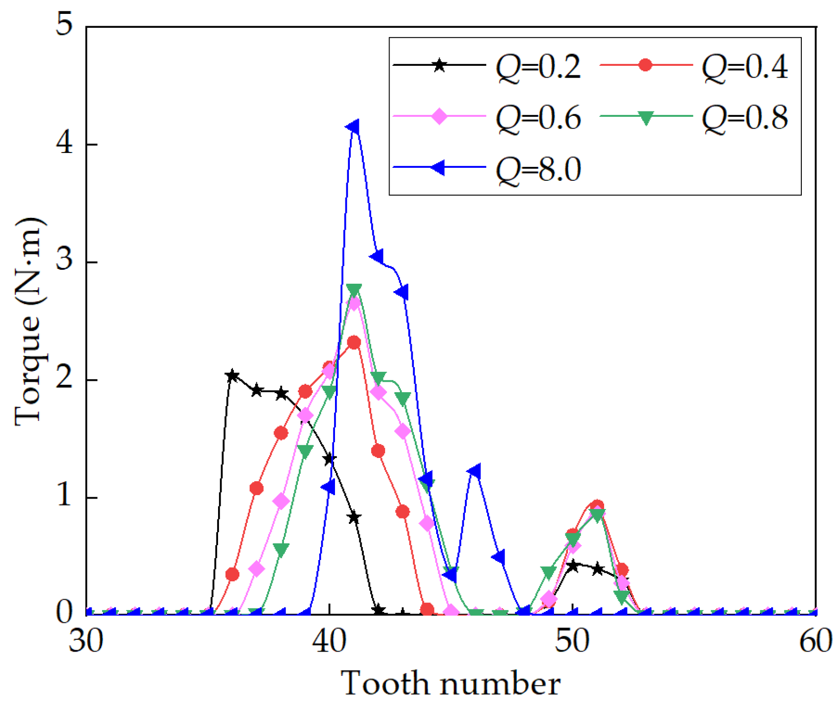
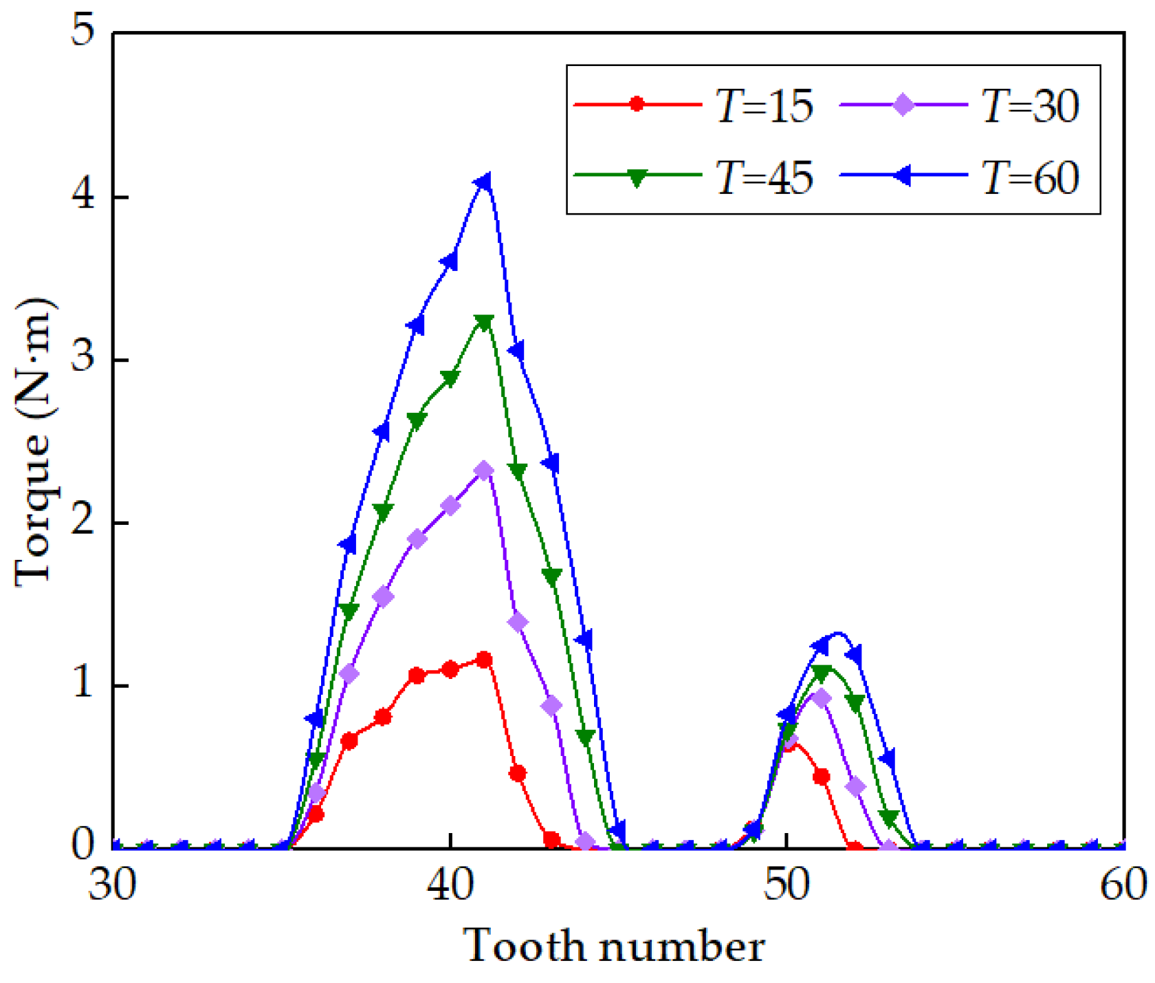
4.5. Effects of Torque on Contact Pressure and Load Sharing

In order to analyze the influence of torque on contact pressure and load sharing among teeth, four sets of different T values (T = 15 N·m, 30 N·m, 45 N·m, and 60 N·m) are taken for contact analysis. The results of this analysis are presented in Figure 26 and Figure 27, illustrating the variations in contact pressure and load sharing among teeth corresponding to different torque.
From Figure 26, it is observed that as torque T gradually increases from 15 N·m to 60 N·m, the maximum contact pressure follows a sequence of 608 MPa, 804 MPa, 947 MPa, and 1071 MPa, respectively. With the increase in torque, the maximum contact pressure also gradually increases. However, the rate of growth slows down. This phenomenon is primarily attributed to the increase in torque, leading to greater deformation of the teeth, reduced clearance between adjacent teeth working surfaces, and more gear teeth entering mesh. Additionally, it is notable that the increase in torque does not alter the position of the contact area of the teeth; rather, it only modifies the size of the contact area.
In Figure 27, it is observed that as torque T increases incrementally from 15 N·m to 60 N·m, the number of engaged teeth near the lower end of the long axis follows a sequence of 10, 13, 15, and 16, respectively. Therefore, as torque T increases, the number of engaged teeth also increases. Furthermore, regardless of the torque T, tooth #41 consistently bears the heaviest load. Hence, the torque T has minimal influence on the load sharing trend among teeth as the position of the gear teeth changes.

5. Conclusions

Shortening the FS increases deformation, reduces gear teeth meshing area, and heightens pressure concentration due to the increased cone angle. Hence, a longitudinal modification method for CS with DCTP teeth was proposed, along with an easy-to-manufacture shaping cutter for processing CS teeth. Additionally, an HD precision and parameterized finite element model was developed. The influences of several important HD parameters on contact pressure and load sharing have been studied. The main conclusions are as follows:
(1)
The longitudinal modification of CS teeth can significantly decrease contact pressure, enhance contact area, and prevent stress concentration at the tooth end for short FS HDs.
(2)
As the FS length-to-diameter ratio increases, the contact area spans the entire tooth surface along the tooth width. Conversely, with a shorter ratio, contact pressure rises sharply, and the contact area diminishes.
(3)
With a fixed modification radius, contact pressure initially decreases and then increases as the FS length-to-diameter ratio rises. Modification improves tooth contact for short FS HDs, but becomes unnecessary or even harmful to achieve optimal contact performance when the ratio exceeds a certain threshold.
(4)
When the WG profile coefficient deviates from the intended radial deformation for the tooth, it leads to tooth contact at the tip of the FS, causing stress concentration. Additionally, this ratio has the most significant influence on load sharing among teeth compared to other parameters.
(5)
As the modification radius increases, the contact pressure exhibits a trend of decreasing first and then increasing. For short FS HDs, there exists an optimal modification radius that can achieve the best contact state.
(6)
With the increase in torque, the maximum contact pressure gradually rises, although at a slower rate. It is notable that the increase in torque does not change the position of the teeth’s contact area but rather adjusts its size.

Author Contributions

Conceptualization, X.H. and H.F.; methodology, X.H. and M.Z.; software, X.H.; validation, X.H. and M.Z.; formal analysis, H.F.; investigation, Z.S.; resources, B.L.; data curation, P.S. and H.L.; writing—original draft preparation, X.H.; writing—review and editing, H.F., M.Z. and Y.G.; visualization, X.H. and H.F.; supervision, Y.G.; project administration, H.F. and Y.G. All authors have read and agreed to the published version of the manuscript.

Funding

This research was funded by the National Natural Science Foundation of China, grant number 52205070.

Data Availability Statement

All relevant data are within the paper.

Acknowledgments

The authors would like to acknowledge the financial aid and support of the National Science Foundation of China (no. 52205070). We also thank the anonymous reviewers and editors for their valuable comments and suggestions.

Conflicts of Interest

The authors declare that they have no known competing financial interests or personal relationships that could have appeared to influence the work reported in this paper.

References

  1. Zhao, J.; Wu, J.; Yan, S. Dynamic modeling and motion precision analysis of spacecraft manipulator with harmonic drive considering the alternate thermal field in orbit. Proc. Inst. Mech. Eng. Part G J. Aerosp. Eng. 2015, 229, 135–148. [Google Scholar] [CrossRef]
  2. He, Y.; Chen, J.; Zhou, X. In-situ fault diagnosis for the harmonic reducer of industrial robots via multi-scale mixed convolutional neural networks. J. Manuf. Syst. 2023, 66, 233–247. [Google Scholar] [CrossRef]
  3. Pham, A.D.; Ahn, H.J. Rigid precision reducers for machining industrial robots. Int. J. Precis. Eng. Manuf. 2021, 22, 1469–1486. [Google Scholar] [CrossRef]
  4. Xing, J.Z.; Pang, M.Y.; Zhang, Z. Optimum of short harmonic drive with variable thickness bottom. J. Tianjin Polytech. Univ. 2019, 38, 74–81. [Google Scholar]
  5. Li, S. Diaphragm stress analysis and fatigue strength evaluation of the flex-spline, a very thin-walled spur gear used in the strain wave gearing. Mech. Mach. Theory 2016, 104, 1–16. [Google Scholar] [CrossRef]
  6. Li, X.; Song, C.; Zhu, C.; Song, H. Load analysis of thin-walled flexible bearing in harmonic reducer considering assembly with flexspline and cam. Mech. Mach. Theory 2023, 180, 105154. [Google Scholar] [CrossRef]
  7. Li, F.; Li, X.; Guo, Y. Analysis of contact mechanical characteristics of flexible parts in harmonic gear reducer. Shock. Vib. 2021, 2021, 5521320. [Google Scholar] [CrossRef]
  8. Yang, C.; Hu, Q.; Liu, Z. Analysis of the partial axial load of a very thin-walled straight-gear (flexspline) of a harmonic drive. Int. J. Precis. Eng. Manuf. 2020, 21, 1333–1345. [Google Scholar] [CrossRef]
  9. Chen, G.; Li, H.; Liu, Y. Double-arc harmonic gear profile design and meshing analysis for multi-section conjugation. Adv. Mech. Eng. 2019, 11, 1687814019850656. [Google Scholar] [CrossRef]
  10. Song, C.; Zhu, F.; Li, X. Three-dimensional conjugate tooth surface design and contact analysis of harmonic drive with double-circular-arc tooth profile. Chin. J. Mech. Eng. 2023, 36, 83. [Google Scholar] [CrossRef]
  11. Zhang, Y.; Pan, X.; Li, Y. Meshing stiffness calculation of disposable harmonic drive under full load. Machines 2022, 10, 271. [Google Scholar] [CrossRef]
  12. Zhang, Y.; Wang, G.; Pan, X. Calculating the load distribution and contact stress of the disposable harmonic drive under full load. Machines 2022, 10, 96. [Google Scholar] [CrossRef]
  13. Ma, J.; Li, C.; Luo, Y. Simulation of meshing characteristics of harmonic reducer and experimental verification. Adv. Mech. Eng. 2018, 10, 1687814018767494. [Google Scholar] [CrossRef]
  14. Yao, Y.; Chen, X.; Xing, J. Tooth position and deformation of flexspline assembled with cam in harmonic drive based on force analysis. Chin. J. Mech. Eng. 2021, 34, 104. [Google Scholar] [CrossRef]
  15. Wang, S.; Jiang, G.; Mei, X. A rapid stress calculation method for short flexspline harmonic drive. Eng. Comput. 2019, 36, 1852–1867. [Google Scholar] [CrossRef]
  16. Qiu, L.; Chen, M.; Song, G. Study on three-dimensional elastic deformation characteristics of flexspline in harmonic drive based on Rayleigh-Ritz method with accelerated convergence strategy. J. Mech. Sci. Technol. 2023, 37, 3615–3629. [Google Scholar] [CrossRef]
  17. Ma, D.H.; Wu, J.N.; Liu, T. Deformation analysis of the flexspline of harmonic drive gears considering the driving speed effect using laser sensors. Sci. China Technol. Sci. 2017, 60, 1175–1187. [Google Scholar] [CrossRef]
  18. Luu, T.; Tran, T.; Wu, Y. A novel topology modification of spur gear flanks to enhance contact performance and lubrication ability. Mech. Mach. Theory 2024, 199, 105670. [Google Scholar] [CrossRef]
  19. Routh, B.; Maiti, R.; Ray, A.K. An investigation on secondary force contacts of tooth pairs in conventional harmonic drive with involute toothed gear set. Proc. Inst. Mech. Eng. Part C J. Mech. Eng. Sci. 2016, 230, 622–638. [Google Scholar] [CrossRef]
  20. Sahoo, V.; Maiti, R. Evidence of secondary tooth contact in harmonic drive, with involute toothed gear pair, through experimental and finite element analyses of pressures in flex-gear cup. Proc. Inst. Mech. Eng. Part C J. Mech. Eng. Sci. 2016, 232, 341–357. [Google Scholar] [CrossRef]
  21. Yang, C.; Ma, H.; Zhang, T. Calculation of tooth thickness errors and its adjustment on meshing backlash of harmonic drive. Int. J. Precis. Eng. Manuf. 2023, 24, 289–301. [Google Scholar] [CrossRef]
  22. Routh, B.; Sahoo, V.; Sobczyk, A. Performance analysis of asymmetric toothed strain wave gear. Proc. Inst. Mech. Eng. Part C J. Mech. Eng. Sci. 2021, 235, 7314–7328. [Google Scholar] [CrossRef]
  23. Yang, C.; Ma, H.; Zhang, T. Research on meshing characteristics of strain wave gearing with three different types of tooth profiles. Int. J. Precis. Eng. Manuf. 2021, 22, 1761–1775. [Google Scholar] [CrossRef]
  24. Ishikawa, S. Tooth Profile of Spline of Strain Wave Gearing. U.S. Patent 4823638, 25 April 1989. [Google Scholar]
  25. Ishikawa, S.; Kiyosawa, Y. Flexing Contact Type Gear Drive of Non-Profile-Shifted Two-Circular-Arc Composite Tooth Profile. U.S. Patent 5458023, 17 October 1995. [Google Scholar]
  26. Song, C.; Li, X.; Yang, Y. Parameter design of double-circular-arc tooth profile and its influence on meshing characteristics of harmonic drive. Mech. Mach. Theory 2022, 167, 104567. [Google Scholar] [CrossRef]
  27. Cheng, Y.H.; Chen, Y.C. A general mathematical modeling and finite element analysis of a strain wave gear possessing a double-circular-arc-with-a-common-tangent profile. Proc. Inst. Mech. Eng. Part C J. Mech. Eng. Sci. 2023, 237, 223–236. [Google Scholar] [CrossRef]
  28. Chen, X.; Liu, Y.; Xing, J.; Lin, S.; Xu, W. The parametric design of double-circular-arc tooth profile and its influence on the functional backlash of harmonic drive. Mech. Mach. Theory 2014, 73, 1–24. [Google Scholar] [CrossRef]
  29. Song, C.; Li, X.; Zhu, C.; Du, X. Parametric analysis of tooth surface characteristics of flexspline in harmonic reducer after hobbing. Mech. Mach. Theory 2024, 194, 105585. [Google Scholar] [CrossRef]
  30. Yang, H.; Li, X.; Xu, J.; Guo, Y.; Li, B. Modeling and Fatigue Characteristic Analysis of the Gear Flexspline of a Harmonic Reducer. Mathematics 2022, 10, 868. [Google Scholar] [CrossRef]
Figure 1. Comparison of (a) cone angle and (b) meshing areas between short and ordinary FS.
Machines 12 00777 g001
Figure 2. Generating methods for CS with tooth longitudinal modification and shaping cutter.
Machines 12 00777 g002
Figure 3. FS tooth profile local coordinate system.
Machines 12 00777 g003
Figure 4. Coordinate systems applied for the derivation of the CS tooth surface mathematical model.
Machines 12 00777 g004
Figure 5. Calculation process for φ1 by discrete s value.
Machines 12 00777 g005
Figure 6. CS tooth profile.
Machines 12 00777 g006
Figure 7. Processing coordinate system of the shaping cutter for machining the CS.
Machines 12 00777 g007
Figure 8. Shaping cutter tooth profile.
Machines 12 00777 g008
Figure 9. Longitudinal modification motion trajectory.
Machines 12 00777 g009
Figure 10. (a) FS structure, (b) single tooth nodes, and (c) FS finite element model.
Machines 12 00777 g010
Figure 11. (a) CS structure, (b) single tooth nodes, and (c) CS finite element model.
Machines 12 00777 g011
Figure 12. (a) FB structure, (b) ball and ring nodes, and (c) FB finite element model.
Machines 12 00777 g012
Figure 13. (a) WG structure, (b) WG nodes, and (c) WG finite element model.
Machines 12 00777 g013
Figure 14. Boundary conditions: (a) interference elimination, (b) WG coupling point, (c) FS coupling point, and (d) load torque.
Machines 12 00777 g014
Figure 15. HDs: (a) numbered FS teeth and (b) contact pressure distribution.
Machines 12 00777 g015
Figure 16. Comparison of contact pressure between CS teeth with and without modification.
Machines 12 00777 g016
Figure 17. Comparison about load sharing between CS teeth with and without modification.
Machines 12 00777 g017
Figure 18. Effects of Q on contact pressure when CS teeth are without longitudinal modification.
Machines 12 00777 g018
Figure 19. Effects of Q on load sharing when CS teeth are without longitudinal modification.
Machines 12 00777 g019
Figure 20. Effects of Q on contact pressure when CS teeth are with longitudinal modification.
Machines 12 00777 g020
Figure 21. Effects of Q on load sharing when CS teeth are with longitudinal modification.
Machines 12 00777 g021
Figure 22. Effects of ε on contact pressure.
Machines 12 00777 g022
Figure 23. Effects of ε on load sharing.
Machines 12 00777 g023
Figure 24. Effects of modification radius on contact pressure.
Machines 12 00777 g024
Figure 25. Effects of modification radius on load sharing.
Machines 12 00777 g025
Figure 26. Effects of T on contact pressure.
Machines 12 00777 g026
Figure 27. Effects of T on load sharing.
Machines 12 00777 g027
Table 1. Double arc tooth profile parameter table.
ParameterParameter DefinitionParameterParameter Definition
haAddendumc1Center displacement of convex arc
hfDedendumc2Center displacement of concave arc
h1Straight tooth profile heightδCommon tangent inclination angle
e1Offset of convex arc centerdsWall thickness of flexspline cylinder
e2Offset of concave arc centerr1Convex arc radius
αTooth tip pressure angler2Concave arc radius
ktTooth thickness coefficientmModulus
Table 2. Table of tooth profile parameters for CS.
ParameterParameter DefinitionParameterParameter Definition
hagAddendumc1gCenter displacement of convex arc
hfgDedendumc2gCenter displacement of concave arc
h1gLinear tooth profile heightδgCommon tangent inclination angle
c1gOffset of convex arc centerαgTooth tip pressure angle
c2gOffset of concave arc centerrgReference radius
r1gConvex arc radiusmModulus
r2gConcave arc radius
Table 3. Basic parameters of FS and CS for analysis.
ParameterValueParameterValue
ha (mm)0.3hag (mm)0.35
hf (mm)0.4hfg (mm)0.35
h1 (mm)0.1508h1g (mm)0.1463
c1 (mm)0.3912c1g (mm)0.3416
c2 (mm)0.2874c2g (mm)0.3327
e1 (mm)0.0732e1g (mm)0.0746
e2 (mm)0.15e2g (mm)0.1485
r1 (mm)0.67r1g (mm)0.6724
r2 (mm)0.8r2g (mm)0.7964
α (°)33.79αg (°)38.53
δ (°)14.74δg (°)14.56
ds (mm)0.4rg (mm)25.5
m (mm)0.5Zr100
Zg102Q0.4
ω00.5R (mm)200
T (N·m)30ε0.5
Table 4. Material mechanics properties of parts of HD components.
ParameterMaterialYoung’s Modulus E (GPa)Poisson’s Ratio v
FS30CrMnNi2040.3
CSQT4002070.3
WGGCr152170.3
Disclaimer/Publisher’s Note: The statements, opinions and data contained in all publications are solely those of the individual author(s) and contributor(s) and not of MDPI and/or the editor(s). MDPI and/or the editor(s) disclaim responsibility for any injury to people or property resulting from any ideas, methods, instructions or products referred to in the content.

