Abstract
Robot-assisted systems for vascular interventional surgery (VIS) have the advantages of high precision and an improved operating environment for the surgeon. However, the current robot-assisted systems cannot completely replace human beings in controlling interventional devices—for example, rapid guidewire/catheter replacement and force feedback. In the face of these challenges, the robot-assisted system presented in this article can better solve the above problems. The experiments for the guidewire and catheter were designed and performed separately based on the developed robot-assisted system. The experimental results show that the participants can use the system to manipulate the guidewire and catheter to reach the designated blood vessel position. Based on the experiments for the catheter, for the first time, the reciprocating manipulation method with visual-based force feedback (VFF) was used for experimental evaluation. The experimental results show that this method can effectively avoid the buckling phenomenon of the catheter; the VFF plays a vital role in improving the safety of the operation and provides an operational assessment of VIS safety. In addition, this article puts forward the evaluation index for maximum pull force (MPLF) and force fluctuation, which provides an essential reference for enriching the evaluation of VIS technical skills.
1. Introduction
Cardiovascular diseases (CVDs) seriously affect human health [1]. The methods for treating these diseases are mainly divided into open surgery and minimally invasive surgery. Minimally invasive surgery is widely used in clinical surgery because of its less traumatic effect, lower pain level, faster postoperative recovery, and potential for performing multiple procedures simultaneously [2]. With the rapid development of medical technology, minimally invasive VIS is gradually being replaced by robot-assisted remote vascular interventional systems. These systems can prevent surgeons from being exposed to X-ray radiation from the digital subtraction angiography (DSA) equipment and improve the operating environment of surgeons. With the help of the robot-assisted remote intervention system, the surgeon can sit in a comfortable seat in the control room outside the operating room and perform surgery by remotely controlling the vascular interventional robot by watching advanced medical imaging equipment [3,4]. This remote robot-assisted interventional technology has a tremendously positive effect on improving the surgeon’s operating experience, increasing the utilization rate of surgeons, prolonging the professional life of surgeons, and improving the uneven distribution of medical resources [4,5]. During the 2019 novel coronavirus pandemic, this technology was able to isolate surgeons and patients, playing an important role [6]. It also improved surgical accuracy and stability compared manual techniques [7,8,9]. This technology effectively filters out the jitter that occurs when the surgeon’s hands interact with the device [10] and expands the surgeon’s field of vision [3,11].
1.1. Current Research Status
The research on robot-assisted VIS systems has attracted the interest of scientific and technological workers worldwide. More and more robot-assisted VIS systems have been invented. The current VIS robots are mainly divided into commercial and laboratory robots.
1.1.1. Commercial Robots
With the urgent needs of markets, some commercial robots have been approved by the Food and Drug Administration (FDA) or Conformite Europeenne (CE) for clinical applications.
In 2012, the CorPath 200 received FDA approval for percutaneous coronary intervention (PCI). However, it does not enable active remote control of the movement of the guide catheter [12]. Based on the CorPath 200, Corindus Vascular Robotics built a second-generation robot called the Corporate GRX robotic system, which received FDA approval in 2016 for PCI and peripheral vascular intervention (PVI) in the USA, and approval for neuroendovascular intervention in the European Union, Australia, and New Zealand [13,14,15]. So far, the CorPath GRX robotic system is the only system approved by the FDA and CE for VIS [16]. The Hansen Medical Sensei system received FDA approval in 2007 for radiofrequency (RF) ablation procedures and cardiac mapping (CM) [15,17]. The robot was then revised and developed into a next-generation system known as the Magellan system, which received FDA approval in 2012 for PVI [2,17,18,19]. The R-One™ robotic device is a fully integrated robotics platform developed by Robocath, founded in 2009 [20]. The system received the CE marking in February 2019 for the teleoperating of guidewires and stents during PCI [21]. The Amigo system received FDA approval for RF ablation and CM [18,22]. Compared to the Sensei system, it does not need to customize proprietary equipment [22]. Some key features and other aspects of these commercial robotic systems are summarized in Table 1. As shown in Table 1, these commercial robotic systems have remote operation functions to improve operation accuracy, effectively help surgeons to avoid X-ray radiation, and provide an excellent clinical effect in VIS. However, these robotic systems do not have force feedback. In fact, relying solely on visual feedback during clinical VIS cannot guarantee the safety of surgery [5]. This thus poses a safety hazard to the extensive clinical application of VIS in the future.

Table 1.
Some commercial robots are commercially licensed and can be used clinically.
1.1.2. Laboratory Robots
Laboratory robots are mainly distributed in universities and research institutes. At Imperial College London, Yang et al. [27] proposed a pneumatically actuated endovascular platform with a teleoperation and navigation framework. An ex vivo performance assessment with clinical experts had better succession rates. At Hong Kong University, Lee et al. [28] proposed a robotic manipulator for the remote manipulation of a cardiac catheter. However, wire entanglement affects this system when the catheter rotates. The above two robotic systems can be suitably and safely used in a magnetic resonance (MR) imaging guiding environment. At the Beijing Institute of Technology, Bao et al. [29] proposed a multilevel concept for operating force as a reference for choosing and designing operation strategies. Based on this concept, a multilevel operation strategy is proposed to reduce blood vessel damage and ensure surgical safety. However, the bottom platform of the follower manipulator is only based on a single slider rail. The follower manipulator will move from side to side during the actual operation, which is inconvenient for the structure’s stability. At Shanghai Jiao Tong University, Peng et al. [30] proposed an ergonomically designed dual-use mechanism that helps to improve learning efficiency and absorb surgeons’ natural operating skills. At Xiamen University, Zhou et al. [31] proposed a simple robotic system with four degrees of freedom (DOFs) which can obtain high precision and stability. Its control method adopts the leader–follower control strategy and has the bending force feedback of the constraint pipe. At the Institute of Automation, Chinese Academy of Sciences, Feng et al. [32,33] proposed a bio-inspired dual-finger robotic hand and a console to assist the surgeon in delivering interventional devices. Its design follows the conventional surgeons’ operating skills. At the University of Ulsan College of Medicine, Choi et al. [34] proposed a robotic system with a catheter, guidewire, and balloon/stent module. However, the roller device is constantly in contact with the catheter, increasing the risk of catheter contamination. At Hanyang University, Song et al. [35] proposed a vascular intervention robotic system with seven DOFs to drive a co-axial catheter-microcatheter system. The experiment proved that the two-DOF ergonomically designed leader device performed better than the two-DOF joystick-type leader device. At Yanshan University, Wang et al. [36] proposed a robot system with force feedback, accurate delivery, and better control performance. At Kagawa University, Zhang et al. [37,38] proposed a robot-assisted catheter system with collision protection that can effectively mitigate collision trauma. The capacity of force measurement has better static and dynamic characteristics. Jin et al. [39,40] proposed a system that has the collision force detection function of a catheter’s tip and an active enhancing safety method to avoid the dangers caused by the surgeon’s misoperation and sudden accidents. Shi et al. [41] proposed a novel follower manipulator with a coordinate system that can quickly exchange the guidewire/catheter. Through the simulation experiment, they verified that the flexible material can protect the catheter’s surface from damage. The above robotic systems’ main contributions and other aspects are summarized in Table 2.
Table 2.
The current research status regarding laboratory robotic systems.
In addition, magnetically controlled robots have developed rapidly in recent years because of their quick response and remote control advantages. At Wuhan University, Shan et al. [42] proposed a cyber-physical system consisting of a magnetic field driven at the follower side and a virtual surgical environment at the leader side. Its system uses a dynamically changing current through the coil to generate a dynamic magnetic field, which can quickly control the direction of the guidewire. At Daegu Gyeongbuk Institute of Science and Technology, Hwang et al. [43] reported that an electromagnetically controllable micro-robot intervention system could help doctors remotely manipulate micro-diameter guidewires in real time and complete cardiovascular interventions in vascular phantoms. At ITMO University, Pozhitkova et al. [44] proposed an attractive solution for thrombosis treatment via reprogrammable magnetic soft robots. At the Massachusetts Institute of Technology, Kim et al. [45] proposed a teleoperated robotic neuro-interventional platform based on magnetic manipulation. This technology opens up the possibility of using remote methods to address challenges in the current stroke care systems.
1.2. Challenges and Contributions
The ultimate purpose of VIS robotic systems is to replace human beings when operating the interventional equipment on site. These systems’ safety performance and operating experience are of great significance to patients and surgeons. When a robot is used in clinical practice, any link that does not conform to clinical practicability may lead to redesigning the entire robotic structure or scrapping it entirely. Given the current research status (Section 1.1), the main contributions of this article are listed below.
- A novel robot-assisted system was conceived and developed to assist surgeons in completing the surgery, which can provide a good sense of tactile presence and a steep learning curve to surgeons, help surgeons to avoid X-ray radiation, and effectively overcome these limitations listed in Table 2.
- To the best of our knowledge, the reciprocating manipulation method with VFF was first proposed to manipulate the catheter to the target position effectively, which can provide enhanced safety considerations for surgeons and avoid the buckling phenomenon of the catheter.
- Novel objective performance metrics are proposed for technical skills’ evaluation, among which the MPLF, reciprocating manipulation number, and force fluctuation, to the best of our knowledge, are less commonly reported.
- The in vitro experiments were designed and completed to evaluate the performance of the controlling guidewire and catheter in the pre-training stage and demonstrate the importance of VFF to improve safety performance in VIS.
The remainder of this article is structured as follows. The robot-assisted system is conceived and developed in Section 2. The relative principles and methods are described in Section 3. The experiments and results are presented in Section 4. The discussion is provided in Section 5. Lastly, Section 6 presents the conclusion of this article.
2. Robot-Assisted System for VIS
2.1. Description of the System
Our robot-assisted system was proposed to improve the surgeon’s operating performance and comfort and enhance the safety of surgery, as shown in Figure 1 [46]. The surgeon controls the movement of the guidewire/catheter at the follower side by controlling the leader manipulator. At this time, the force sensors (load cell and torque sensors) are built into the follower manipulator and the position sensor (laser sensor) is placed on the outside of the follower manipulator, and the relative measured data (force and displacement information) are transmitted to the leader manipulator through the control unit. The force information is transmitted to the surgeon’s hand in real time through physics-based force feedback (PFF) at the leader side. Position information is delivered to a screen in front of the surgeon’s eyes through visual feedback. With an internet protocol (IP) camera on the patient and the follower manipulator, respectively, the surgeon can observe the movement displacement of the guidewire/catheter in the blood vessel and conditions of the guidewire/catheter at the follower side in a timely manner. These measures ensure that the entire operation is monitored. The robot-assisted system helps surgeons to feel like they are using their hands to manipulate the guidewire/catheter onsite.
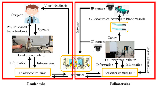
Figure 1.
The schematic diagram of the robot-assisted system.
It is worth noting that implementing physics-based force feedback requires the following two points: (1) the leader manipulator needs to have a function for realizing the output force (introduced in Section 2.2); and (2) the follower manipulator needs to have a device for measuring the force information of the guidewire/catheter (introduced in Section 2.3).
2.2. Leader Manipulator
The leader manipulator is in direct contact with the surgeon’s hands. It can provide PFF to the surgeon’s hand. PFF is realized via the magnetorheological (MR) fluids (MRF-122EG, Lord Crop., Cary, NC, USA) in the container, as shown in Figure 2 [38,47]. MR fluids are intelligent materials and were used as controllable fluids to mimic the compressional compliance of biological tissues to realize a haptic display. The material properties of MR fluids can be expressed as:
where is the shear stress, η is the plastic viscosity, is the magnetic field-dependent yield stress, is the magnetic field, and is the shear strain rate.
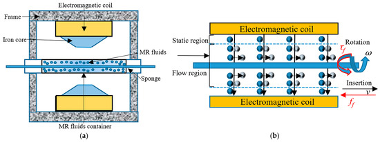
Figure 2.
(a) Schematic diagram of the leader manipulator; (b) the principle of PFF generated by MR fluids.
When , MR fluids present Newton-like behavior. When , MR fluids present Bingham behavior. In this case, the properties of MR fluids can be effectively controlled through the magnetic field. The magnetic field generator consists of two symmetrical electromagnetic coils, two iron cores (cylinder with a circular truncated cone made of SS400 STEEL, JIS), and a frame supporting them. The parameters of the coil in the magnetic field generator are shown in Table 3 [48]. The relationship between the magnetic field and the input current can be established by experiments [48]. The changing magnetic field is controlled by controlling the magnitude of the current. A current driver provides current control. Therefore, a certain relationship between the shear force and current can be established. The control method of this relationship can be realized by adopting a closed-loop proportional–integral–derivative (PID) controller [48]. Therefore, the nonlinear relationship between the axial force feedback (or the radial force feedback) and the amount of current can be calculated and fitted through test calibrations [49,50]. The leader manipulator used in this article represents the continuation of this research.
Table 3.
The parameters of the coil and the copper wire.
The technical parameters of the leader haptic device are shown in Table 4. As shown in Figure 3, the surgeon manipulates the operating handling device to control the movement of the guidewire/catheter on the follower side. The movement information of the operating handling device is collected by two encoders (MES020-2000p, MTL, Sagamihara, Japan). Based on the leader manipulator, two operation interfaces were integrated and formed into the leader side. Operation interface one can view the movement status of the guidewire/catheter in the endovascular evaluator (EVE) model and the situation of the follower manipulator controlling the guidewire/catheter through IP cameras. Operation interface two can view the force information of the moving guidewire/catheter (vision-based force feedback) based on operation interface one.
Table 4.
The technical parameters of the leader haptic device.
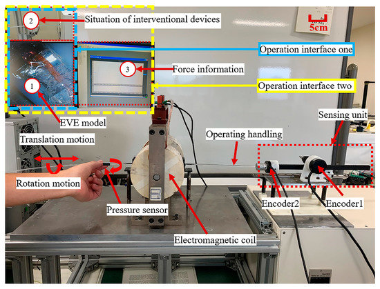
Figure 3.
The leader manipulator is based on MR fluids at the leader side.
2.3. Follower Manipulator
The follower manipulator directly interacts with interventional devices such as guidewires or catheters. Its function is to replicate the operational information of the human hand from the leader manipulator to realize the purpose of operating the guidewire/catheter instead of the human. In addition, the follower manipulator needs to provide the primary force information to the leader manipulator, which is used by the leader manipulator as the basis for realizing PFF. Therefore, a load cell (TU-UJ5N, TEAC, Tokyo, Japan) and torque sensors (RLW05m, Takasu Giken, Kyoto, Japan) are integrated into the follower manipulator to detect the axial and radial force information of the guidewire/catheter in motion. The developed follower manipulator is shown in Figure 4 [46].
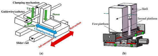
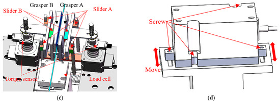
Figure 4.
Follower manipulator with force detection structure. (a) Simple schematic diagram of the follower manipulator–controlling guidewire/catheter movement principle; (b) schematic diagram of the follower manipulator (including the shell); (c) schematic diagram of force detection; (d) schematic diagram of adjustable load cell installation.
The movement mode and detailed structure of the follower manipulator-controlled catheter were introduced in an earlier article [46]. Models and numbers of components used in the follower manipulator are shown in Table 5. The power transmission mechanisms of the follower manipulator were adopted as follows: axial motion, ball screw + slider + slider rail; rotation motion (twisting), screw + slider + slider rail. Compared to the equipment of the laboratory robots in the introduction section, this follower manipulator and the whole system overcome the above limitations listed in Table 2. In addition, this follower manipulator also has the following advantages: it is compatible with various types of guidewire/catheter sizes, it follows the operation habits of conventional surgeons in operating guidewires/catheters, and so on [46].
Table 5.
Models and numbers of components used in the follower manipulator.
3. Principles and Methods
The follower manipulator controls the guidewire/catheter instead of the surgeon controlling it in the operating room. However, in the process of an actual operation, due to the length of the catheter and its material properties, buckling occurs during the procedure. This phenomenon is not conducive to the continuous advancement of the catheter. Therefore, this part will describe and analyze this phenomenon and introduce the methods adopted to avoid this problem. In addition, the force of pulling a catheter will be analyzed.
3.1. The Buckling Phenomenon of the Catheter
The schematic diagram of the force information of when the catheter enters the blood vessel from the sheath is shown in Figure 5. When the push force () controls the catheter to move it forward, the catheter will experience some resistance in the blood vessel. These resistances include the tip collision force (), the contact friction force between the vessel wall and the catheter ( or ) [51], and the friction of blood against the catheter. In addition, the vascular sheath also has a certain clamping force () on the catheter, and friction will be generated when the catheter moves [39]. These forces can be transformed into a resultant force () along the axial direction of the catheter. This can be translated into forces ( and ) as described above [52]. The angle between and is , and the angle between and is .
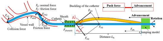
Figure 5.
The buckling phenomenon of the catheter.
The actual blood vessel situation is much more intricate than in Figure 5. However, in general, compared with the previous analyses [53,54], the forces on the catheter can be expressed by the following equations:
where is the total force, is the viscosity drag force, is the contact friction force, is the tip collision force, is the force from the sheath, and is the external force (including the friction force from the guidewire).
Furthermore, some forces in Equation (4) can be expressed as follows:
where is the viscosity coefficient of the blood, is the velocity of catheter intervention, is the interfacial viscosity shear strength, is the real contact area, is the dynamic friction coefficient between the catheter surface and the vessel wall, is the normal load, R is the diameter of the catheter, dl is the length, is the pressure distributed along the length direction, L is the length of the catheter in the blood vessel, is the count of contact points according to the statistical approach, is the adhesive force (surface tension), is the contact stiffness parameter, denotes the damping coefficient of viscosity of collision contact, represents the relative indentation between the catheter tip and the vessel wall, is the relative normal collision contact velocity, is the coefficient of friction between the catheter surface and the sheath, and is the clamping force from the sheath.
As shown in Figure 5, the distance from the clamping position of the follower manipulator to the sheath is . In the range of distance , due to the characteristics of the flexible material of the catheter itself, at this distance, the catheter cannot be guaranteed to be in a horizontal straight line (along the axial direction of the catheter). These factors cause the following phenomena to occur when advancing the catheter.
When the value of is relatively large, the distance is relatively large, and under the influence of the force (), the catheter tends to bend in this direction (see Figure 5). As a result of this tendency, the catheter cannot continue to move forward. If the catheter continues to be pushed forward at this time, the catheter will continue to deepen in its bending direction and even cause a certain degree of damage to the catheter at its crease point . This causes the shape of the catheter to be permanently deformed at its crease point [55]. When this part of the deformation enters the patient’s body, it will cause inevitable damage (such as thrombosis [56,57]) to the patient’s vessels and cause certain obstacles to the intervention and manipulation of subsequent intervention equipment (such as a guidewire, stent, microcatheter, micro-guidewire). Therefore, the real-time monitoring and avoidance of this phenomenon are of great significance for improving the security of system operation.
In order to avoid the occurrence of this buckling phenomenon, there are the following solutions.
- 1
- Use a scissor-type mechanism [58] (see Figure 6a), catheter sleeve [59] (see Figure 6b), telescopic mechanism [60], origami-based anti-buckling system [55], zipper-type mechanism [61], slider-based supporting structure [62], spirally collapsible structure [63], two-way chain [64], coiled return spring [65], or active feeder mechanism [66]. These measures can effectively mitigate the buckling phenomenon and increase the amount of lateral force.
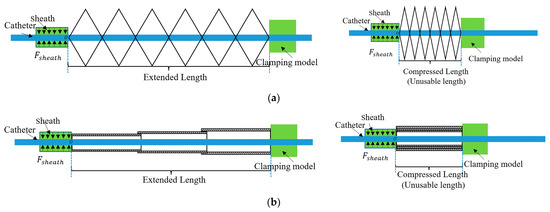 Figure 6. Schematic diagram of anti-buckling devices’ extension and compression. (a) Schematic diagram of fully extended and compressed scissor-type mechanism; (b) schematic diagram of fully extended and compressed catheter sleeve.
 - 2
- Reduce the distance appropriately to ensure that the catheter maintains a certain rigidity within this distance.
- 3
- Adopt methods that utilize a certain degree of rigidity of the catheter to advance the catheter continuously.
For method 1, these methods [55,58,59,60,61,62,63,64,65] passively support mechanisms for buckling prevention. The active feeding mechanism [66] adopts an active method to carry out buckling prevention of the catheter. Its straightforward method uses the catheter-driving unit and feeder mechanism to operate synchronously. This anti-buckling structure design causes the curved catheter to come into contact with it and causes some friction. For systems with PFF, introducing this friction will threaten the accuracy and effectiveness of PFF [50]. As shown in Figure 6, when fully compressed, there will be a certain amount of the catheter that cannot be used. The design of the anti-buckling structure reduces the effective stroke of the catheter to a certain extent, which is inevitable. Standard catheters are expensive, and their length is limited. Therefore, introducing this anti-buckling structure is not conducive to the full use of the effective length of the catheter, resulting in a waste of some resources. The design of the anti-buckling systems brings a certain degree of redundancy to the system, which is not conducive to the flexible manipulation and rapid replacement of the catheter. These anti-buckling systems increase the part count and size and are inconvenient to place near a patient due to their bulky structures [66]. In addition, it is also necessary to consider the issues of disinfection and infection [56,57] and whether these anti-buckling structures affect the catheter’s movement (translation and rotation) [66].
Therefore, methods 2 and 3 are used comprehensively to avoid this phenomenon as much as possible. In this article, the distance of is 4.5 cm, and the reciprocating manipulation method is adopted (introduced in Section 3.3).
3.2. Force Analysis of Pulling a Catheter
When withdrawing the catheter or when the front-end position of the catheter needs to be readjusted, the catheter must be pulled. The force analysis when the catheter is pulled is shown in Figure 7. This resultant force () can be translated into forces ( and ). The angle between and is , and the angle between and is . At this time, and are almost equal to . Compared with Figure 5, it can be found that the significant difference is that the resultant force on the catheter will be mainly distributed on the axial force line of the catheter. In this case, the catheter will not buckle due to the force component. As shown in Figure 7, the distance from the clamping position of the follower manipulator to the sheath is .
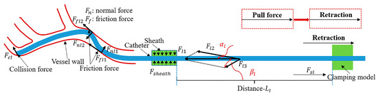
Figure 7.
The force analysis of pulling a catheter.
When removing the catheter quickly, there will be a certain acceleration in the whole catheter at this time, . The mass of the catheter remains the same; in this case, will increase. Due to the characteristics of the flexible material of the catheter itself, the catheter will maintain its original position, so the collision force () will be present. Due to the presence of acceleration, in Equation (7), the will increase as the increases. In Equation (5), the will increase as the v increases. In Equation (6), the will increase as the increases. Therefore, the increase in these friction forces will potentially increase the contact between the catheter and the vessel wall resulting in the risk of secondary injury to the vessel wall. Especially for diseased and weakened vessel walls, this may cause thrombosis, dissection, or embolization [67].
The curved shape of the blood vessel in the actual intervention process is more intricate than that in Figure 7.
3.3. Reciprocating Manipulation Method
As stated in Section 3.1, the design of anti-buckling devices will bring about a series of problems. Inspired by surgeons’ conventional operation habits [68], the reciprocating manipulation method proposed is shown in Figure 8. This method can avoid the occurrence of these problems caused by the anti-buckling devices, thereby simplifying the system’s complexity and laying the foundation for the miniaturization of system devices in the future. In addition, it respects surgeons’ conventional operation habits, facilitates surgeons’ understanding and learning, and can absorb the operational experience of conventional surgeons.
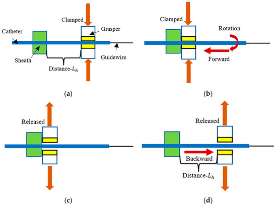
Figure 8.
A schematic diagram of the reciprocating manipulation method. (a) “clamp”—the grasper is positioned at a distance from the sheath, and at the initial position, the grasper clamps the catheter; (b) “forward (rotation)”—the grasper clamps the catheter for forward or rotational movement until the position of the grasper reaches the position of the sheath; (c) “release”—after reaching the position of the sheath, the grasper releases the catheter; (d) “backward”—the grasper returns to its initial position.
As shown in Figure 8, a complete reciprocating cycle is “”a”–“b”–“c”–“d”“. This is a reciprocating manipulation method, repeated until the catheter is manipulated to the target position.
4. Experiments and Results
The characteristics of the follower manipulator were introduced earlier in this article. Next, the in vitro experiments were carried out to evaluate the guidewire and catheter performance.
There were two experiments: (1) a guidewire manipulation experiment and (2) a catheter manipulation experiment. In the experiment, the reciprocating manipulation method with VFF was performed for the first time.
4.1. Guidewire Manipulation Experiments and Results
4.1.1. Experimental Setup
Compared with the catheter, the length of the guidewire is longer; the guidewire will not affect the sheath, and the diameter of the guidewire is relatively thin. Its head is made from a softer material with better flexibility and will suffer less friction in the blood vessel than the catheter [39]. In the actual vascular intervention process, the role of the guidewire is mainly reflected in the selection of the direction of the catheter and some necessary supports for the catheter. Therefore, at the vessel bifurcation of the blood vessel, by manipulating the guidewire, the target blood vessel bifurcation can be conveniently selected through the head of the guidewire and then entered into the target blood vessel. Then, the catheter will be guided by the guidewire. With the support of the guidewire, the process of reaching the target blood vessel position is more convenient [46].
In order to better reflect the actual intervention process of the guidewire and create an actual operating environment, and to verify the actual control performance of the follower manipulator on the guidewire, the following experimental setup was designed. The design of the experimental setup mainly included two parts: (1) designing the experimental setup before entering the EVE model (Fain-biomedical, Nagoya, Japan); (2) designing the experimental environment in the EVE model.
The experimental setup for part 1 is shown in Figure 9. The end of the catheter (SZ3502, MEDIKIT, Tokyo, Japan) is fixed. The catheter enters the EVE model through a sheath. The follower manipulator controls the guidewire (RF-GA35153, Terumo, Tokyo, Japan). Figure 9a shows the model diagram of the guidewire manipulation experiment. Figure 9b shows the guidewire manipulation experiment’s physical setup.
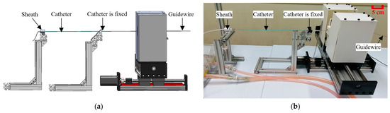
Figure 9.
Guidewire manipulation experimental setup. (a) Guidewire manipulation experimental model diagram; (b) guidewire manipulation experiment’s physical setup.
The experimental setup for part 2 is shown in Figure 10. Figure 10a includes the EVE model and IP camera (SD8111, VIVOTEK, San Jose, USA). As shown in Figure 10b, the circulatory pump (KB-4N, Iwaki, Tokyo, Japan) simulates the human heart to provide water circulation for the EVE model. The choice of the experimental vessel path of the guidewire in the EVE model needs to consider the vascular difficulty [69]. It can objectively reflect the dexterity skills of novices and experts and simultaneously reflect the performance of interventional robots before entering clinical practice. Therefore, the designed physical position of the guidewire and the selected experimental vessel path name in the EVE model are shown in Figure 11 and Figure 12a, respectively. As shown in Figure 12b, from the initial position of the guidewire to the target position, its required length is approximately 10.8 cm.
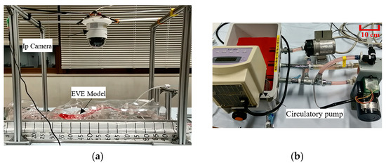
Figure 10.
Experimental environment. (a) The EVE model and IP camera; (b) circulatory pump.
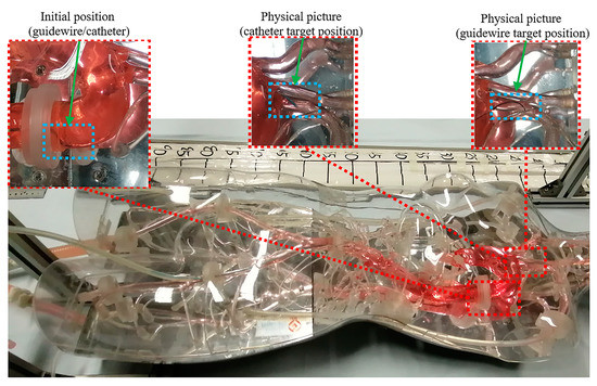
Figure 11.
The overall physical situation of the guidewire and catheter in the EVE model.
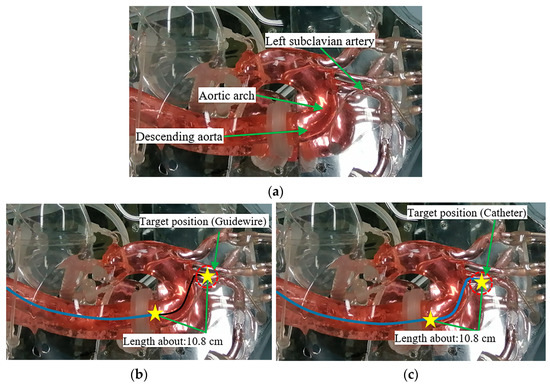
Figure 12.
(a) Experimental vessel path names; (b) schematic of guidewire’s length from the initial position to the target position; (c) schematic of catheter’s length from the initial position to the target position. The solid blue line represents a catheter, the solid black line represents a guidewire, and the two yellow stars represent the initial and target positions.
4.1.2. Experimental Methods
The diameter of the guidewire is relatively thin, and the guidewire will not be affected by the force of the sheath (see Figure 5). Hence, the force on the guidewire is generally tiny. The designed control method of the guidewire is shown in Figure 13. The principle adopts the linear dragging control method, and the guidewire is controlled from the initial position until the guidewire reaches the target position, wherein the distance from the clamping position of the follower manipulator to the end of the catheter is greater than 10.8 cm (see Figure 12b).
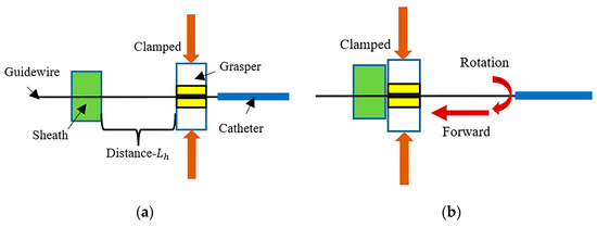
Figure 13.
Schematic diagram of the linear dragging control method. (a) At the initial position, the grasper clamps the guidewire; (b) it clamps the guidewire for forward or rotational movement until the guidewire arrives at the target position.
The participant operates on the leader manipulator, and the participant’s leader manipulator experimental setup is shown in Figure 3. The participant chooses operation interface one. In this experiment, to increase the experimental difficulty, the circulatory pump is turned off. The friction between the guidewire and the vessel wall will increase in this case. Thus, it can better reflect the participant’s operational skills and the effect of the experiment. In order to facilitate the operational skills of a beginner, the human-controlled guidewire rotates at a low speed (pre-training stage), and its maximum rotation speed is 11 r/min. The experimental purpose is to use the system to maneuver the guidewire from the initial position to the target position as fast as possible.
4.1.3. Experimental Results
Two participants manipulated the guidewire from the initial position to the target position. One was an inexperienced participant, and the other was a participant with a high level of operating experience. The operation results are shown in Figure 14. The results of the operation time and the maximum push force (MPHF) on the guidewire during the operation are shown in Table 6. Compared to Equation (4), the forces on the guidewire can be expressed by Equation (9) [39,53,54].
where is the total force, is the viscosity drag force, is the contact friction force, is the tip collision force, and is the external force (including the friction force from the catheter).
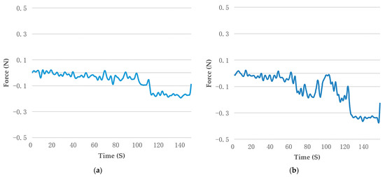
Figure 14.
The real-time force measurement of the guidewire. (a) The results of the experienced participant; (b) the results of the inexperienced participant.
Table 6.
Detailed real-time force measurement of the guidewire.
The operating force is measured by a built-in sensor load cell (TU-UJ5C, TEAC, Tokyo, Japan) of the follower manipulator (see Figure 4c). The data sampling frequency of the load cell is set to 200 ms. It is worth emphasizing that the force measured by a load cell is the proximal axial force of the guidewire including the total force () acting on the axial direction of the guidewire. The axial force can be simplified as the push force and pull force (see Figure 5 and Figure 7). It can be seen from Figure 14 that both participants can use the robotic system to control the guidewire to reach the target position. The operating force information curve of the experienced participant is smoother and more stable than that of the inexperienced participant. As shown in Table 6, the experienced participant can not only shorten the operation time but also effectively reduce the axial force on the guidewire by controlling the movement of the guidewire in the EVE model. This is because experienced participants tend to be more familiar with the anatomy of the human vascular system and are equipped with certain technical skills required to manipulate the guidewire.
4.2. Catheter Manipulation Experiments and Results
4.2.1. Experimental Setup
Guidewires and catheters are very commonly used interventional devices in actual interventional procedures. Compared with the guidewire’s length, the catheter’s length is shorter. In the actual vascular intervention process, the catheter often enters the blood vessel through a sheath and advances in the blood vessel under the guidance of the guidewire. The diameter of the catheter is thicker than the guidewire, and its internal space can accommodate the passage of the guidewire and related stents, as well as the injection of related contrast agents. Catheters are usually composed of flexible materials. In order to facilitate the catheter to enter the target blood vessel bifurcation, there are different curved catheters on the market for different blood vessel shapes [70]. The control performance of the follower manipulator on the guidewire is presented in Section 4.1. Therefore, it is necessary to design and perform experiments to verify the control performance of the follower manipulator on the catheter. The experimental setup for part 1 is shown in Figure 15. The end of the guidewire (RF-GA35153, Terumo, Tokyo, Japan) is fixed. The catheter (SZ3502, MEDIKIT, Tokyo, Japan) enters the EVE model through a sheath. The follower manipulator controls the catheter. Figure 15a shows the model diagram of the catheter manipulation experiment. Figure 15b shows the catheter manipulation experiment’s physical setup.
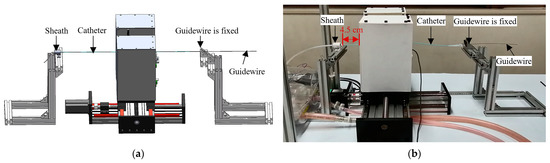
Figure 15.
Catheter manipulation experimental setup. (a) Catheter manipulation experimental model diagram; (b) catheter manipulation experiment’s physical setup.
The experimental setup for part 2 is shown in Figure 10. Considering the vascular difficulty [69], the left subclavian artery is chosen as the research target. In addition, to increase the difficulty of the experiment, in this article, the control catheter is not operated with the support of the guidewire, and the catheter is controlled independently to reach the designated position. Correspondingly, the designed physical position of the guidewire and catheter is shown in Figure 11. As shown in Figure 12c, from the initial position of the catheter to the target position, its required length is approximately 10.8 cm.
4.2.2. Experimental Methods
As illustrated in Section 3.1, to avoid the buckling phenomenon as much as possible, the reciprocating manipulation method is adopted (see Figure 8), and the distance is 4.5 cm (see Figure 15b). Therefore, maneuvering the catheter to the target position requires advancing it at least three times.
The participant operates on the leader manipulator, and the participant’s leader manipulator experimental setup is shown in Figure 3. The participant chooses operation interface one or two. In this experiment, the circulatory pump is turned on. Similarly, to facilitate beginners’ operation, the human-controlled catheter rotates at a low speed (pre-training stage), and its maximum rotation speed is 11 r/min. The experimental purpose is to use the system to maneuver the catheter from the initial position to the target position as fast as possible.
4.2.3. Experimental Results
Five participants participated in the experiment. In the cases of operation interface one or two, the operation method (see Figure 8) was used to operate the catheter from the initial position to the target position. The results obtained are shown in the figures below.
Figure 16a shows the operation time comparison of the five participants. It can be seen from these data that under the operation with VFF, the operating time has increased. This is mainly because the participants need to observe the force information of the operation at all times, and this condition will increase the participants’ external attention to a certain extent so that they can operate carefully.
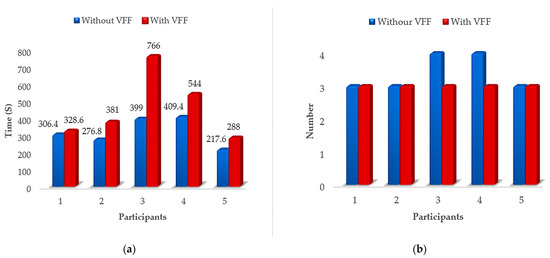
Figure 16.
Operation results of five participants. (a) The results of the operating time; (b) the results of the reciprocating manipulation number.
Figure 16b shows the results of the reciprocating manipulation number. For the sake of brevity, the reciprocating manipulation number in this article is counted as the number of “”c”–“d”–“a”“ plus 1, which is the reciprocating manipulation number in the test (see Figure 8). When operating the catheter, due to unreasonable operation, the front end of the catheter is crowded and unable to advance. Therefore, it is necessary to readjust the catheter to an appropriate position and cause the reciprocating manipulation number to be greater than the theoretical value (3 times). As shown in Figure 16b, under the operation without VFF, participants 3 and 4 used more than the basic reciprocating manipulation number to finally cause the catheter to reach the target position. From the perspective of force information feedback, having VFF can better help participants to focus on controlling the movement of the catheter and shorten the reciprocating manipulation number to three times.
From the point of view of the operation time and reciprocating manipulation number of participants, the introduction of VFF brought about certain changes. Therefore, it is necessary to carefully analyze the operation situation under the operation without or with VFF. As can be seen from Figure 16, when participant 2 operates without or with VFF, the operation time fluctuates significantly, the required reciprocation manipulation number remains unchanged, and the time spent before and after is relatively small; when participant 3 operates without or with VFF, the operating time fluctuates the most, the reciprocating manipulation number changes, and the operating time before and after is the largest. In addition, participant 2 is a participant with a high level of operating experience. Participant 3 is a first-contact participant with no operational experience. Therefore, based on the above, participants 2 and 3 are analyzed as typical examples of the operating force situation.
The results of operating force information for participants 2 and 3 under the operation without or with VFF are shown in Figure 17. The operating force is measured using a built-in sensor load cell (TU-UJ5C, TEAC, Tokyo, Japan) of the follower manipulator (see Figure 4c). The data sampling frequency of the load cell is set to 200 ms. It is worth emphasizing that the force measured by a load cell is the proximal axial force of the catheter including the total force () acting on the axial direction of the catheter (see Equation (4)). The axial force can be simplified as the push force and pull force (see Figure 5 and Figure 7). As shown in Figure 17a,b,d, the reciprocating manipulation number (”c”–“d”–“a”) is two. In fact, the total reciprocating manipulation number is three. Figure 17a,b show the axial force information situation of the catheter for participant 2 under the operation without or with VFF. Figure 17c,d show the axial force information situation of the catheter for participant 3 under the operation without or with VFF.
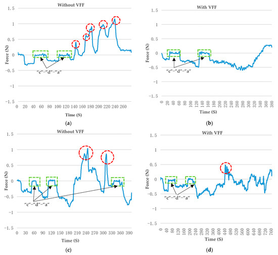
Figure 17.
Axial force information situation of the catheter for participants 2 and 3 under the operation without or with VFF. Participant 2 is an experienced participant. Participant 3 is inexperienced. (a) The catheter force information results for participant 2 under the operation without VFF; (b) the catheter force information results for participant 2 under the operation with VFF; (c) the catheter force information results for participant 3 under the operation without VFF; (d) the catheter force information results for participant 3 under the operation with VFF. The red circle marks a peak of the local MPLF. The green box indicates a reciprocating manipulation method (”c”–“d”–“a”), as shown in Figure 8.
As shown in Figure 17a,c, the participants all have some local MPLF peaks. A quick pull on the catheter causes this in an attempt to adjust the position of the catheter quickly. Some local MPLF values almost reach the safe threshold of 1 N [38], which may have caused a certain safety hazard for VIS. As shown in Figure 17, the experienced participant not only demonstrates a shorter operation time, but their operating force information curve is smoother and more stable than that of the novice, whether under the operation without or with VFF. VFF can effectively assist participants in controlling and reducing pulling force fluctuation. Therefore, from the perspective of force fluctuation, the statistical results of the five groups of experimental data regarding the MPLF and MPHF are examined, as shown in Figure 18.
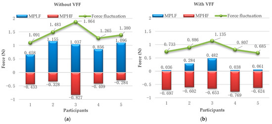
Figure 18.
The statistical results of five groups of experimental data on force fluctuation. (a) Operation results under the operation without VFF; (b) operation results under the operation with VFF.
From Figure 18, the following results can be obtained.
- (1)
- From the perspective of MPLF, the MPLF was significantly reduced under the operation with VFF; the force exceeded the safety threshold (1N) for participants 2, 3, and 5 [38,49], as shown in Figure 18a; and quickly withdrawing the catheter will cause a relatively large pull force, increasing the risk of secondary damage to the blood vessel. Figure 18b shows all the participants’ MPLF within the safety threshold.
- (2)
- (3)
- From the perspective of the safety threshold, when the force exceeds the safety threshold, this will increase the potential safety risk of damaging the vessel wall; if the force fluctuation is below the safety threshold, the MPLF and MPHF have to be below the safety threshold; and as shown in Figure 18b, all participants’ MPLF and MPHF were below the safety threshold under the operation with VFF; therefore, this reciprocating manipulation method with VFF positively reduces the risk of damaging the vessel wall.
5. Discussion
Considering the challenges in Section 1, this article presented a conceived and developed robotic system that can effectively overcome the limitations listed in Table 2. Based on this robotic system, the performance evaluation experiments for controlling the guidewire and catheter were designed and completed in the EVE model, simulating an actual human vascular system. For the guidewire performance evaluation experiments, the linear drag method was adopted. For the catheter performance evaluation experiments, the reciprocating manipulation method with VFF was adopted to avoid the buckling phenomenon of the catheter. This experiment used experience and inexperience, comparing experiments without VFF and with VFF. To the best of our knowledge, the experimental results of technical skills’ evaluation, the MPLF, the reciprocating manipulation number, and force fluctuation were evaluated for the first time. For the force fluctuation, if force fluctuation is smaller than the safety threshold, the system’s performance has to be safe. Through the discussion with the participants who experienced the experiments, we found that they think that VFF is a vital tool to provide safety when guiding them to finish the task. In addition, technical skills can be mastered by practicing the task repeatedly. In terms of visual feedback, the participants think that it is hard to judge the situation when moving the catheter in the EVE model because the catheter in the vascular system is in a three-dimensional environment. In experiments, solely relying on the video from the top view to judge the contact situation of the catheter and the vessel walls is challenging. Therefore, it will be helpful to judge the catheter and the vascular situation through previous experience based on VFF and visual feedback. However, it may require some time for thought.
For the catheter experiments, as shown in Figure 17, the ““c”–”d”–”a”” process time is always different because this process is operated manually, and different participants may have different operation times. In this process, it needs to be repeated many times. So, this reciprocating manipulation process can be processed into an automation procedure. Therefore, this helps to reduce the surgeon’s burden and improve the system’s dexterity. In addition, for the follower manipulator, the developed structure for holding will be designed and integrated into the existing system. In this article, an assistant participant replaced the catheter’s holding function. Comparing the results of Figure 14 and Figure 17, the axial force on the guidewire is obviously smaller than that on the catheter. The reason for this can be found in Equations (4) and (9). Some forces in Equations (4) and (9) can be achieved via experiments or analytical models, which can be found in previous works [39,51]. As shown in Figure 18, the MPHF increased under the operation with VFF, which may be related to the radial force of the catheter. Therefore, this should be verified by experiments in the future. When under the operation with VFF, the participants always paid attention to the control of the rotation motion of the catheter.
Because the current research in this article focuses on the evaluation of the basic properties of the proposed system, some issues will be solved to improve a practical system in the future: First, this article indicates the importance of VFF, while it does not involve PFF. In the future, the comparative importance of VFF and PFF will be analyzed independently and in combination. Second, due to the limited number of experimental participants in this article, more participants need to be recruited for data collection and analysis to verify the conclusions of this article in experiments. Third, the VFF involves the guidewire/catheter proximal axial force in this article. It still needs to combine the radial force, displacement, speed, etc., for the guidewire/catheter to collect and present the experienced participants’ technical skills. Fourth, a fluoroscopy device will be used instead of an IP camera to better reflect the actual experimental environment in the EVE model.
6. Conclusions
In this article, a reciprocating manipulation method with VFF was first proposed to manipulate the catheter to the target position effectively, which can provide enhanced safety considerations for surgeons and avoid the buckling phenomenon of the catheter. Novel objective performance metrics are proposed for technical skill evaluation. To the best of our knowledge, the MPLF, reciprocating manipulation number, and force fluctuation have yet to be reported. The in vitro experiments were designed and completed to evaluate the performance of the controlling guidewire and catheter in the pre-training stage. The importance of using VFF to improve the safety performance of VIS was verified via our experiments.
Author Contributions
C.S. conceived and designed the robot-assisted system, performed the data collection, and drafted sections of the manuscript. H.I. guided the evaluation experiments and reviewed the manuscript. All authors have read and agreed to the published version of the manuscript.
Funding
This research was partly supported by the China Scholarship Council Grant Number 202208050086.
Institutional Review Board Statement
The study was conducted according to the guidelines of the Declaration of Helsinki and approved by the Institutional Review Board (IRB) in the Faculty of Engineering Kagawa University (Ref. No. 01-011 from February 2020).
Informed Consent Statement
Informed consent was obtained from all subjects involved in the study.
Data Availability Statement
The data presented in this study are available on request from the corresponding author.
Conflicts of Interest
The authors declare no conflict of interest.
References
- WHO. World Health Statistics 2020: Monitoring Health for the SDGs, Sustainable Development Goals; World Health Organization: Geneva, Switzerland, 2020; Available online: https://www.who.int/publications/i/item/9789240005105 (accessed on 20 May 2023).
- Püschel, A.; Schafmayer, C.; Groß, J. Robot-assisted techniques in vascular and endovascular surgery. Langenbecks Arch. Surg. 2022, 407, 1789–1795. [Google Scholar] [CrossRef] [PubMed]
- Guan, S.; Li, T.; Meng, C.; Ma, L. Multi-mode information fusion navigation system for robot-assisted vascular interventional surgery. BMC Surg. 2023, 23, 51. [Google Scholar] [CrossRef] [PubMed]
- Xia, S.-B.; Lu, Q.-S. Development status of telesurgery robotic system. Chin. J. Traumatol. 2021, 24, 144–147. [Google Scholar] [CrossRef] [PubMed]
- Beaman, C.; Kaneko, N.; Meyers, P.; Tateshima, S. A review of robotic interventional neuroradiology. AJNR Am. J. Neuroradiol. 2021, 42, 808–814. [Google Scholar] [CrossRef]
- Tabaza, L.; Virk, H.u.H.; Janzer, S.; George, J.C. Robotic-assisted percutaneous coronary intervention in a COVID-19 patient. Catheter. Cardiovasc. Interv. 2021, 97, E343–E345. [Google Scholar] [CrossRef] [PubMed]
- Nogueira, R.G.; Sachdeva, R.; Al-Bayati, A.R.; Mohammaden, M.H.; Frankel, M.R.; Haussen, D.C. Robotic assisted carotid artery stenting for the treatment of symptomatic carotid disease: Technical feasibility and preliminary results. J. NeuroInterv. Surg. 2020, 12, 341–344. [Google Scholar] [CrossRef]
- George, J.C.; Tabaza, L.; Janzer, S. Robotic-assisted balloon angioplasty and stent placement with distal embolic protection device for severe carotid artery stenosis in a high-risk surgical patient. Catheter. Cardiovasc. Interv. 2020, 96, 410–412. [Google Scholar] [CrossRef]
- Britz, G.W.; Tomas, J.; Lumsden, A. Feasibility of robotic-assisted neurovascular interventions: Initial experience in flow model and porcine model. Neurosurgery 2020, 86, 309–314. [Google Scholar] [CrossRef]
- Zheng, L.; Guo, S. A magnetorheological fluid-based tremor reduction method for robot-assisted catheter operating system. Int. J. Mechatron. Autom. 2021, 8, 72–79. [Google Scholar] [CrossRef]
- Nguyen, C.C.; Wong, S.; Thai, M.T.; Hoang, T.T.; Phan, P.T.; Davies, J.; Wu, L.; Tsai, D.; Phan, H.P.; Lovell, N.H. Advanced user interfaces for teleoperated surgical robotic systems. Adv. Sens. Res. 2023, 2, 2200036. [Google Scholar] [CrossRef]
- Britz, G.W.; Panesar, S.S.; Falb, P.; Tomas, J.; Desai, V.; Lumsden, A. Neuroendovascular-specific engineering modifications to the CorPath GRX Robotic System. J. Neurosurg. 2019, 133, 1830–1836. [Google Scholar] [CrossRef] [PubMed]
- Pereira, V.M.; Cancelliere, N.M.; Nicholson, P.; Radovanovic, I.; Drake, K.E.; Sungur, J.-M.; Krings, T.; Turk, A. First-in-human, robotic-assisted neuroendovascular intervention. J. NeuroInterv. Surg. 2020, 12, 338–340. [Google Scholar] [CrossRef] [PubMed]
- Sajja, K.C.; Sweid, A.; Al Saiegh, F.; Chalouhi, N.; Avery, M.B.; Schmidt, R.F.; Tjoumakaris, S.I.; Gooch, M.R.; Herial, N.; Abbas, R. Endovascular robotic: Feasibility and proof of principle for diagnostic cerebral angiography and carotid artery stenting. J. NeuroInterv. Surg. 2020, 12, 345–349. [Google Scholar] [CrossRef] [PubMed]
- Menaker, S.A.; Shah, S.S.; Snelling, B.M.; Sur, S.; Starke, R.M.; Peterson, E.C. Current applications and future perspectives of robotics in cerebrovascular and endovascular neurosurgery. J. NeuroInterv. Surg. 2018, 10, 78–82. [Google Scholar] [CrossRef] [PubMed]
- Chen, P.; Wang, Y.; Tian, D.; Guo, Y.; Xu, K. The Catheter and Guidewire Operating Systems of Vascular Interventional Surgical Robots: A Systematic Review. IEEE Trans. Med. Robot. Bionics 2023, 5, 180–195. [Google Scholar] [CrossRef]
- Cercenelli, L.; Bortolani, B.; Marcelli, E. CathROB: A highly compact and versatile remote catheter navigation system. Appl. Bionics Biomech. 2017, 2017, 2712453. [Google Scholar] [CrossRef]
- Condino, S.; Piazza, R.; Carbone, M.; Bath, J.; Troisi, N.; Ferrari, M.; Berchiolli, R. Bioengineering, augmented reality, and robotic surgery in vascular surgery: A literature review. Front. Surg. 2022, 9, 966118. [Google Scholar] [CrossRef]
- Riga, C.V.; Bicknell, C.D.; Rolls, A.; Cheshire, N.J.; Hamady, M.S. Robot-assisted fenestrated endovascular aneurysm repair (FEVAR) using the Magellan system. J. Vasc. Interv. Radiol. 2013, 24, 191–196. [Google Scholar] [CrossRef]
- R-One Robotic Device for Interventional Cardiology Procedures. Available online: https://www.medicaldevice-network.com/projects/r-one-robotic-device/ (accessed on 20 May 2023).
- Nicholls, M. Mark Nicholls speaks to Professor Eric Durand and Professor Rémi Sabatier about Europe’s first remote robotic-assisted angioplasty procedure. Eur. Heart J. 2021, 42, 3033–3035. [Google Scholar] [CrossRef]
- Shaikh, Z.A.; Eilenberg, M.F.; Cohen, T.J. The Amigo™ remote catheter system: From concept to bedside. J. Innov. Card. Rhythm. Manag. 2017, 8, 2795. [Google Scholar] [CrossRef]
- Crinnion, W.; Jackson, B.; Sood, A.; Lynch, J.; Bergeles, C.; Liu, H.; Rhode, K.; Pereira, V.M.; Booth, T.C. Robotics in neurointerventional surgery: A systematic review of the literature. J. NeuroInterv. Surg. 2022, 14, 539–545. [Google Scholar] [CrossRef]
- Cruddas, L.; Martin, G.; Riga, C. Robotic endovascular surgery: Current and future practice. Semin. Vasc. Surg. 2021, 34, 233–240. [Google Scholar] [CrossRef]
- R-oneTM Safety Information. Available online: https://www.robocath.com/wp-content/uploads/2022/09/Robocath_Safety-information-def-EN.pdf (accessed on 20 May 2023).
- Khan, E.M.; Frumkin, W.; Ng, G.A.; Neelagaru, S.; Abi-Samra, F.M.; Lee, J.; Giudici, M.; Gohn, D.; Winkle, R.A.; Sussman, J. First experience with a novel robotic remote catheter system: Amigo™ mapping trial. J. Interv. Card. Electrophysiol. 2013, 37, 121–129. [Google Scholar] [CrossRef] [PubMed]
- Kundrat, D.; Dagnino, G.; Kwok, T.M.; Abdelaziz, M.E.; Chi, W.; Nguyen, A.; Riga, C.; Yang, G.-Z. An MR-Safe endovascular robotic platform: Design, control, and ex-vivo evaluation. IEEE Trans. Biomed. Eng. 2021, 68, 3110–3121. [Google Scholar] [CrossRef] [PubMed]
- Lee, K.-H.; Fu, K.C.D.; Guo, Z.; Dong, Z.; Leong, M.C.; Cheung, C.-L.; Lee, A.P.-W.; Luk, W.; Kwok, K.-W. MR safe robotic manipulator for MRI-guided intracardiac catheterization. IEEE ASME Trans. Mechatron. 2018, 23, 586–595. [Google Scholar] [CrossRef]
- Bao, X.; Guo, S.; Guo, Y.; Yang, C.; Shi, L.; Li, Y.; Jiang, Y. Multilevel operation strategy of a vascular interventional robot system for surgical safety in teleoperation. IEEE Trans. Robot. 2022, 38, 2238–2250. [Google Scholar] [CrossRef]
- Peng, W.; Wang, Z.; Xie, H.; Gu, L. Design, development and evaluation of an ergonomically designed dual-use mechanism for robot-assisted cardiovascular intervention. Int. J. Comput. Assist. Radiol. Surg. 2023, 18, 205–216. [Google Scholar] [CrossRef]
- Zhou, J.; Mei, Z.; Miao, J.; Mao, J.; Wang, L.; Wu, D.; Sun, D.; Zhao, Y. A remote-controlled robotic system with safety protection strategy based on force-sensing and bending feedback for transcatheter arterial chemoembolization. Micromachines 2020, 11, 805. [Google Scholar] [CrossRef] [PubMed]
- Feng, Z.-Q.; Bian, G.-B.; Xie, X.-L.; Hou, Z.-G.; Hao, J.-L. Design and evaluation of a bio-inspired robotic hand for percutaneous coronary intervention. In Proceedings of the 2015 IEEE International Conference on Robotics and Automation (ICRA), Seattle, WA, USA, 26–30 May 2015; pp. 5338–5343. [Google Scholar]
- Bian, G.-B.; Xie, X.-L.; Feng, Z.-Q.; Hou, Z.-G.; Wei, P.; Cheng, L.; Tan, M. An enhanced dual-finger robotic Hand for Catheter manipulating in vascular intervention: A preliminary study. In Proceedings of the 2013 IEEE International Conference on Information and Automation (ICIA), Yinchuan, China, 26–28 August 2013; pp. 356–361. [Google Scholar]
- Choi, J.; Park, S.; Kim, Y.-H.; Moon, Y.; Choi, J. A vascular intervention assist device using bi-motional roller cartridge structure and clinical evaluation. Biosensors 2021, 11, 329. [Google Scholar] [CrossRef]
- Song, H.-S.; Woo, J.-H.; Won, J.-Y.; Yi, B.-J. In Vivo Usability Test of Vascular Intervention Robotic System Controlled by Two Types of Master Devices. Appl. Sci. 2021, 11, 5453. [Google Scholar] [CrossRef]
- Wang, H.; Chang, J.; Yu, H.; Liu, H.; Hou, C.; Lu, H. Research on a novel vascular interventional surgery robot and control method based on precise delivery. IEEE Access 2021, 9, 26568–26582. [Google Scholar] [CrossRef]
- Zhang, L.; Guo, S.; Yu, H.; Song, Y.; Tamiya, T.; Hirata, H.; Ishihara, H. Design and performance evaluation of collision protection-based safety operation for a haptic robot-assisted catheter operating system. Biomed. Microdevices 2018, 20, 22. [Google Scholar] [CrossRef]
- Zhang, L.; Gu, S.; Guo, S.; Tamiya, T. A magnetorheological fluids-based robot-assisted catheter/guidewire surgery system for endovascular catheterization. Micromachines 2021, 12, 640. [Google Scholar] [CrossRef]
- Jin, X.; Guo, S.; Guo, J.; Shi, P.; Tamiya, T.; Kawanishi, M.; Hirata, H. Total force analysis and safety enhancing for operating both guidewire and catheter in endovascular surgery. IEEE Sens. J. 2021, 21, 22499–22509. [Google Scholar] [CrossRef]
- Jin, X.; Guo, S.; Guo, J.; Shi, P.; Kawanishi, M.; Hirata, H. Active suppression method of dangerous behaviors for robot-assisted vascular interventional surgery. IEEE Trans. Instrum. Meas. 2022, 71, 4004809. [Google Scholar] [CrossRef]
- Shi, C.; Guo, S. Evaluation of a Clamping Mechanism for Vascular Interventional Surgery Robotic System. In Proceedings of the 2021 IEEE International Conference on Mechatronics and Automation (ICMA), Takamatsu, Japan, 8–11 August 2021; pp. 1044–1049. [Google Scholar]
- Shan, C.; Zhao, J.; Zhao, W.; Zhang, T.; Du, B.; Yuan, Z. Magnetic-Actuated Cyber-Physical System for Interventional Surgery. Hum. Centric Comput. Inf. Sci. 2022, 12, 37. [Google Scholar]
- Hwang, J.; Jeon, S.; Kim, B.; Kim, J.y.; Jin, C.; Yeon, A.; Yi, B.J.; Yoon, C.H.; Park, H.J.; Pané, S. An Electromagnetically Controllable Microrobotic Interventional System for Targeted, Real-Time Cardiovascular Intervention. Adv. Healthc. Mater. 2022, 11, 2102529. [Google Scholar] [CrossRef] [PubMed]
- Pozhitkova, A.V.; Kladko, D.V.; Vinnik, D.A.; Taskaev, S.V.; Vinogradov, V.V. Reprogrammable soft swimmers for minimally invasive thrombus extraction. ACS Appl. Mater. Interfaces 2022, 14, 23896–23908. [Google Scholar] [CrossRef] [PubMed]
- Kim, Y.; Genevriere, E.; Harker, P.; Choe, J.; Balicki, M.; Regenhardt, R.W.; Vranic, J.E.; Dmytriw, A.A.; Patel, A.B.; Zhao, X. Telerobotic neurovascular interventions with magnetic manipulation. Sci. Robot. 2022, 7, eabg9907. [Google Scholar] [CrossRef] [PubMed]
- Shi, C.; Guo, S.; Kawanishi, M. Design and Performance Evaluation of a Novel Slave System for Endovascular Tele-Surgery. Machines 2022, 10, 795. [Google Scholar] [CrossRef]
- Yin, X.; Guo, S.; Xiao, N.; Tamiya, T.; Hirata, H.; Ishihara, H. Safety operation consciousness realization of a MR fluids-based novel haptic interface for teleoperated catheter minimally invasive neurosurgery. IEEE ASME Trans. Mechatron. 2015, 21, 1043–1054. [Google Scholar] [CrossRef]
- Yin, X.; Guo, S.; Hirata, H.; Ishihara, H. Design and experimental evaluation of a teleoperated haptic robot–assisted catheter operating system. J. Intell. Mater. Syst. Struct. 2016, 27, 3–16. [Google Scholar] [CrossRef]
- Jin, X.; Guo, S.; Guo, J.; Shi, P.; Tamiya, T.; Hirata, H. Development of a tactile sensing robot-assisted system for vascular interventional surgery. IEEE Sens. J. 2021, 21, 12284–12294. [Google Scholar] [CrossRef]
- Shi, C.; Ishihara, H. Development of a Master-Slave Robotic System for Vascular Interventional Surgery. In Proceedings of the 2022 International Symposium on Micro-NanoMehatronics and Human Science (MHS), Nagoya, Japan, 27–30 November 2022; pp. 1–6. [Google Scholar]
- Liu, J.; Cao, L.; Miyasaka, M.; Phee, S.J. A Frictional Contact-Pattern-Based Model for Inserting a Flexible Shaft into Curved Channels. IEEE ASME Trans. Mechatron. 2021, 27, 2556–2567. [Google Scholar] [CrossRef]
- Wei, W.; Yang, D.; Li, L.; Xia, Y. An Intravascular Catheter Bending Recognition Method for Interventional Surgical Robots. Machines 2022, 10, 42. [Google Scholar] [CrossRef]
- Guo, S.; Song, Y.; Yin, X.; Zhang, L.; Tamiya, T.; Hirata, H.; Ishihara, H. A novel robot-assisted endovascular catheterization system with haptic force feedback. IEEE Trans. Robot. 2019, 35, 685–696. [Google Scholar] [CrossRef]
- Yin, X.; Guo, S.; Wang, Y. Force model-based haptic master console design for teleoperated minimally invasive surgery application. In Proceedings of the 2015 IEEE International Conference on Mechatronics and Automation (ICMA), Beijing, China, 2–5 August 2015; pp. 749–754. [Google Scholar]
- Sargent, B.; Butler, J.; Seymour, K.; Bailey, D.; Jensen, B.; Magleby, S.; Howell, L. An origami-based medical support system to mitigate flexible shaft buckling. J. Mech. Robot. 2020, 12, 041005. [Google Scholar] [CrossRef]
- Smith, R.S.; Zhang, Z.; Bouchard, M.; Li, J.; Lapp, H.S.; Brotske, G.R.; Lucchino, D.L.; Weaver, D.; Roth, L.A.; Coury, A. Vascular catheters with a nonleaching poly-sulfobetaine surface modification reduce thrombus formation and microbial attachment. Sci. Transl. Med. 2012, 4, 153ra132. [Google Scholar] [CrossRef]
- Raad, I.I.; Hohn, D.C.; Gilbreath, B.J.; Suleiman, N.; Hill, L.A.; Bruso, P.A.; Marts, K.; Mansfield, P.F.; Bodey, G.P. Prevention of central venous catheter-related infections by using maximal sterile barrier precautions during insertion. Infect. Control Hosp. Epidemiol. 1994, 15, 231–238. [Google Scholar] [CrossRef]
- Tanner, N.A.; Miller, T.; Sewell, C.M.; Walker, S.P. Systems and Methods for Positioning an Elongate Member Inside a Body. U.S. Patent 10130427, 20 November 2018. [Google Scholar]
- Bao, X.; Guo, S.; Xiao, N.; Li, Y.; Yang, C.; Shen, R.; Cui, J.; Jiang, Y.; Liu, X.; Liu, K. Operation evaluation in-human of a novel remote-controlled vascular interventional robot. Biomed. Microdevices 2018, 20, 34. [Google Scholar] [CrossRef]
- Cha, H.-J.; Yoon, H.-S.; Jung, K.; Yi, B.-J.; Lee, S.; Won, J. A robotic system for percutaneous coronary intervention equipped with a steerable catheter and force feedback function. In Proceedings of the 2016 IEEE/RSJ International Conference on Intelligent Robots and Systems (IROS), Daejeon, Republic of Korea, 9–14 October 2016; pp. 1151–1156. [Google Scholar]
- Sargent, B.; Bean, M.; Wood, D.; Jensen, B.; Magleby, S.; Howell, L. Zipper tube reinforcement to mitigate flexible shaft buckling. In Proceedings of the 2018 International Conference on Reconfigurable Mechanisms and Robots (ReMAR), Delft, The Netherlands, 20–22 June 2018; pp. 1–9. [Google Scholar]
- Sargent, B.S.; Magleby, S.P.; Jensen, B.D.; Howell, L.L. Retractable anti-buckling support systems for flexible medical devices. In Proceedings of the International Design Engineering Technical Conferences and Computers and Information in Engineering Conference, Quebec City, QC, Canada, 26–29 August 2018; p. V05AT07A015. [Google Scholar]
- Fenech, C.M. Variable-Length Guide Apparatus for Delivery of a Flexible Instrument and Methods of Use. U.S. Patent US10682192B2, 16 June 2020. [Google Scholar]
- Fenech, C.; Castaneda, E.; Duindam, V. Guide Apparatus for Delivery of a Flexible Instrument and Methods of Use. U.S. Patent US10206747B2, 19 February 2019. [Google Scholar]
- Fenech, C.M.; Castaneda, E.; Goodman, B.E. Guide Apparatus for Delivery of a Flexible Instrument and Methods of Use. U.S. Patent US10413372B2, 17 September 2019. [Google Scholar]
- Baek, H.; Cheon, B.; You, J.M.; Kwon, D.-S. Design and analysis of feeder mechanism for buckling prevention in robotic catheterization. J. Comput. Des. Eng. 2022, 9, 1467–1481. [Google Scholar] [CrossRef]
- Dagnino, G.; Liu, J.; Abdelaziz, M.E.; Chi, W.; Riga, C.; Yang, G.-Z. Haptic feedback and dynamic active constraints for robot-assisted endovascular catheterization. In Proceedings of the 2018 IEEE/RSJ International Conference on Intelligent Robots and Systems (IROS), Madrid, Spain, 1–5 October 2018; pp. 1770–1775. [Google Scholar]
- Wang, K.; Lu, Q.; Chen, B.; Shen, Y.; Li, H.; Liu, M.; Xu, Z. Endovascular intervention robot with multi-manipulators for surgical procedures: Dexterity, adaptability, and practicability. Robot. Comput. Integr. Manuf. 2019, 56, 75–84. [Google Scholar] [CrossRef]
- Guo, J.; Li, M.; Wang, Y.; Guo, S. An Image Information-Based Objective Assessment Method of Technical Manipulation Skills for Intravascular Interventions. Sensors 2023, 23, 4031. [Google Scholar] [CrossRef] [PubMed]
- OPTITORQUE® Coronary Diagnostic Catheter. Available online: https://www.terumois.com/products/catheters/optitorque.html (accessed on 20 May 2023).
Disclaimer/Publisher’s Note: The statements, opinions and data contained in all publications are solely those of the individual author(s) and contributor(s) and not of MDPI and/or the editor(s). MDPI and/or the editor(s) disclaim responsibility for any injury to people or property resulting from any ideas, methods, instructions or products referred to in the content. |
© 2023 by the authors. Licensee MDPI, Basel, Switzerland. This article is an open access article distributed under the terms and conditions of the Creative Commons Attribution (CC BY) license (https://creativecommons.org/licenses/by/4.0/).