Abstract
Comb-plate expansion joints are widely used in bridge construction, and their failures are mainly static strength and fatigue. This paper used a new type of comb-plate expansion joint as the research object. Firstly, the finite element models (FEM) of the comb-plate expansion joint with minimum and maximum openings were established by Ansys software. Then, the equivalent stress, vertical deformation, and shear stress of the expansion joint under these two working conditions were checked with code. The results showed that the static strength of the expansion joints met the code requirements under both working conditions. Secondly, to investigate the service span of the comb-plate expansion joint, the fatigue life of the expansion joint was predicted using nCode DesignLife software, and the results showed that the minimum fatigue life of the expansion joint was 2.012 × 10⁶ times, which is higher than the 2 × 10⁶ times specified in the code. Finally, a fatigue test of 2 million times was carried out on the full-size expansion joint. Failure modes such as deformation, fracture, or breakage hardly appeared after the fatigue test, demonstrating the reliability of this new type of comb-plate expansion joint.
1. Introduction
Statistics released by the Chinese Ministry of Transport state that with increased national infrastructure investment and attention. The mileage of highways in China will have exceeded 5 million kilometers by 2023. And the development of the expansion joint has contributed to the construction of bridges and highways. Expansion joints are mainly made of rubber, steel, and other components indispensable in bridge structures. The destination of the expansion joint is to accommodate the relative movement between the bridge deck and abutments to ensure the serviceability of bridges [1]. Nowadays, more and more companies have developed their mature product. Namely, MAURER in German, D.S. BROWN and Watson Bowman in the United States, Mageba in Switzerland, and BRITFLEX in the United Kingdom.
Due to the increase incessantly in the vehicle’s speed and load, expansion joints are the vulnerable parts of the bridge, and the probability of damage is very high. The maintenance costs related to expansion joints can reach 20% of the total bridge maintenance costs [2]. Common diseases of the comb plate expansion joint can be classified into several categories: ulnar-plate fall-off caused by anchor bolt damage, concrete damage under the tooth plate, loosening and failure of the bolts, etc. And these damages are not easily detectable during the serving of the bridge. Alternatively, the traffic may be interrupted during the replacement or maintenance of expansion joints, thus affecting the normal operation of bridges. Therefore, paying attention to the fatigue life of comb plate expansion joints is of great practical significance. Surveys have indicated that the service life of expansion joints is frequently much lower than expected. For instance, the Akashi-Kaikyo Bridge, the world’s longest suspension bridge span of 1991 m, experienced fatigue cracks in the connection pin of the expansion joints only three years after the bridge was opened to traffic [3]. The suspension Runyang Bridge with a main span of 1490 m suffered the need for the expansion joints to be repaired after a three-year service [4]. The suspension Jiangyin Bridge with a main span of 1385 m, suffered excessive wear and transversal shear failure of bearings in expansion joints after only four years since operation [5]. The expansion joints in the Martinus Nijhoff Bridge have been repaired several times in recent years [6].
At the beginning of this century, Guo, and Liu [5] clarified the failure mechanism of the expansion joints in a suspension bridge through field tests and numerical studies. They put forward suggestions to improve expansion joint performance finally. Chang and Lee [1] recommended extending the service life method by comparing the fatigue performance of various expansion joints. Marques Lima and de Brito [7] conducted an inspection survey of expansion joints in road bridges and suggested several defect types and maintenance methods for bridge expansion. The above research mainly focused on the cause and control of the failure of expansion joints during long-term service. The specific life value of the expansion joint has hardly been investigated.
Crocetti and Edlund [8] studied the impact load and fatigue life of some modular expansion joints (MBEJ) in the United States through tests and finite element modeling. Wang [9] conducted a fatigue test for the modular beam expansion joint by an MTS fatigue test machine and found that an increase in the number of fatigue cycles led to a rise in the residual strain at the key position and the growth rate of the cumulative residual strain increased significantly with the increase of the load amplitude. Additionally, Artmont and Roy [10] performed an infinite fatigue life assessment of modular beam expansion joints by a full-scale test. Using time-history dynamic analysis, Stamatopoulos [11] developed a fatigue life prediction model for single-supported composite bridge expansion joints connected by bolts. Zhang [12] used a finite element model to simulate the stress of a Maurer bridge expansion joint and estimated the fatigue life. Chaallal [13] conducted a fatigue test for the modular beam expansion joint of the Jacques Cartier bridge. Three types of cracks were observed in the test, and an evaluation method for the fatigue mechanism of expansion was proposed. Guizani [14] performed the experimental and analytical investigation on the fatigue performance of a single-support bar modular bridge expansion joint with welded stirrups and established the experimental fatigue S-N curve for the main critical details. Ma [15] performed fatigue and static loading tests for modular bridge expansion joints. A theoretical fatigue performance assessment method on MBEJs was introduced, based on the nominal stress method and a linear Miner damage accumulation rule. While the number of specimens should be tested to demonstrate the S-N curves and the fatigue stress expression of the expansion joint. A modular joint was fatigue tested under the infinite life regime according to American Association of State Highway and Transportation Officials (AASHTO) specifications by Mahmoud [16]. As mentioned in literature [17], bridge expansion joint contains many interacting components, and each modular has unique (often patented) features developed by the producer. These complicate the load distribution and evaluation process, i.e., each new structure needs to be considered individually. This results in very few studies on the fatigue life of expansion joints, mainly through full-scale fatigue tests. To study the fatigue mechanism of expansion joints via fatigue simulation and full-scale fatigue test, the design duration can be significantly reduced, and the reliability of expansion joints can be improved affirmatively.
In this paper, the object of this research is a new comb plate expansion joint of the bridge, which has the distinct merit of being boltless, as the loosening or failure of bolts could result in a considerable negative influence on the service of the bridge. To investigate the mechanical properties of this new comb-plate expansion joint. This paper is organized as follows. First, the equivalent stress, deformation, and shear stress of the expansion joint at the maximum opening amount and the minimum opening amount were evaluated using Ansys software. Secondly, nCode DesignLife software concerning fatigue life prediction was adopted to predict the fatigue life of the expansion joint. As a result, the minimum life in the structure was recognized as the fatigue life of the entire device. Thirdly, the comb plate expansion joint bench fatigue test was performed following industry code JT/T327-2016 [18] in domestic. The full-scale fatigue test results show that the expansion joint was intact after 2 million cycles. It is noted that the test results also nearly agreed with the simulation results obtained by nCode DesignLife 2020 R2 software.
2. Finite Element Analysis of the Expansion Joint
The new comb plate expansion joint comprises a movable comb plate, fixed comb plate, anchor system, support system, steel groove, and rubber bearing, as depicted in Figure 1. The total length and width are 1000 mm × 500 mm approximately. The boltless is the most advantage of this new type of expansion joint. The anchor system and the comb plates are connected by welding. Similarly, the supported system and fixed comb plate are connected by welding. The anchor system is situated in the concrete of the bridge.
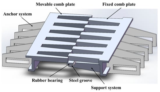
Figure 1.
The sketch of a comb plate bridge expansion joint.
2.1. Analysis of the Working Condition of the Expansion Joint
According to the code [18], the axle load of the vehicle is taken to be 200 kN. Taking the impact coefficient into account, the vertical action of a tyre on the expansion joint, the wheel load is 100 kN. A wheel landing area of 200 × 600 mm2 was demonstrated in code JTG D60-2015 [19].
When the expansion joint experienced the minimum opening amount of 10 mm, and the overlapping length of the comb plate was 250 mm, the contact surface of the tyre and the comb plate is illustrated in Figure 2a. A1 represents the contact area between the wheel and the cast concrete of the bridge. A2 is the contact area between the wheel and the movable comb plate. A3 denotes the non-contact area. A4 signifies the contact area between the wheel and the fixed comb plate. The minimum opening amount of the expansion joint is defined as a working condition I in this work. The wheel load was distributed to the comb plate expansion joint based on these mentioned contact areas. The vertical load and horizontal load acting on the comb plate expansion joint was calculated by Equations (1) and (2).
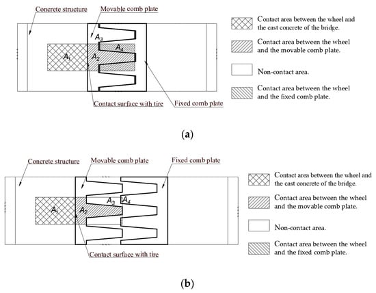
Figure 2.
The contact area under the two working conditions: (a)The working condition I, (b) The working condition II.
When the expansion joint experienced the maximum opening amount, and the overlapping length of the comb plate was 10 mm, the contact surface of the tyre and the comb plate is described in Figure 2b. The maximum opening amount of the expansion joint is defined as working condition II in this work. The wheel load was distributed to the comb plate expansion joint based on the contact area in working condition II. The vertical load and horizontal load acting on the comb plate expansion joint was calculated by Equations (3) and (4).
2.2. FEM of the Comb Plate Expansion Joint under Working Conditions I and II
The materials of the anchor system, support system, comb plates, and steel groove are all Q355 steel, and the material of the rubber bearing is neoprene. The minimum values of mechanical properties are listed in Table 1.

Table 1.
Material characteristics of the expansion device.
The anchor system and support system were simulated by shell element 281. Shell element 281 is suitable for analyzing thin to moderately thick shell structures. The movable comb plate, fixed comb plate, steel groove, and rubber bearing were simulated via solid element 186. Solid element 186 is a quadratic three-node beam element in 3-D. In other words, both elements are well-suited for linear applications. Since there is no concrete structural part in the model, only the part of the tyre interacting with the expansion joint, with an area of 245 × 200 mm2, is considered in the finite element analysis and testing accordingly.
In terms of working conditions, I, as seen in Figure 3, to simulate the contact effect of the tyre on the expansion device, a solid element with a dimension of 245 mm × 200 mm × 20 mm was established in the middle of the movable plate. A vertical load of 56.75 kN and a horizontal load of 16.31 kN were applied to this solid element. In particular, the horizontal and vertical loads were divided equally among nine key points for better simulating the contact between the tyre and the expansion joint. Besides, all displacement of the anchor system was constrained. As a result, the frictional contact pair was built on the contact surface between the comb plate and solid element shown in Figure 3b, and the friction coefficient μ is 0.3. In terms of working condition II, as mentioned in Equations (3) and (4), a vertical load of 43.3 kN and a horizontal load of 12.44 kN were applied to the solid element differently, as shown in Figure 4a. The frictional contact pair under working condition II was built on the contact surface between the comb plate and solid element, as shown in Figure 4b. In this way, the finite element model (FEM) of the comb plate expansion joint under working condition II was established, shown in Figure 4.
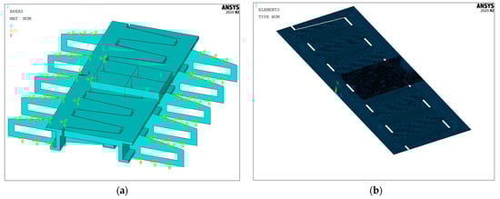
Figure 3.
The finite element modelling for a working condition I: (a) FEM of comb plate expansion, (b) The contact pair.
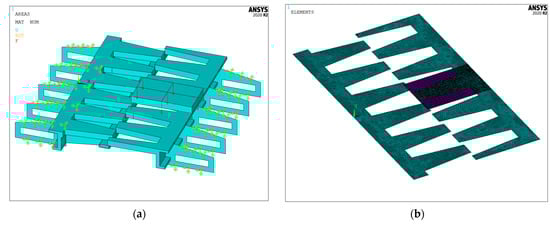
Figure 4.
The finite element modelling for working condition II: (a) FEM of comb plate expansion, (b) The contact pair.
The size of the elements of the FEM of the comb plate expansion joint is 5 mm. The total number of elements and nodes was 452,464 and 727,419. The finite element mesh for the two working conditions is shown in Figure 5.
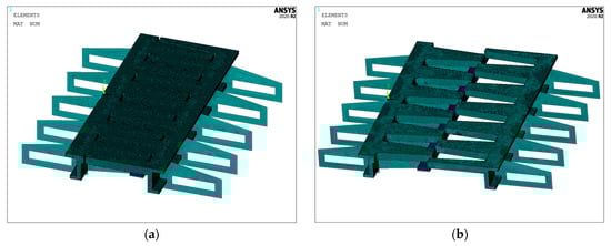
Figure 5.
The finite element meshing for working conditions: (a) working condition I, (b) working condition II.
2.2.1. Stress Evaluation under Working Condition I and II by FEM
As we can see from Figure 6, the maximum equivalent stress of the expansion device is 259.42 MPa under the working condition I. Moreover, the danger point is located at the connection between the movable plate and the middle anchor. For working condition II, as shown in Figure 7, the maximum equivalent stress of the expansion device is 284.64 MPa. The danger point is located at the connection between the fixed plate and the middle anchor. Therefore, the maximum equivalent stress of the expansion device under two work conditions is less than the permissible stress of 236 MPa for Q335 steel. The equivalent stress of structures is detailed in Table 2.
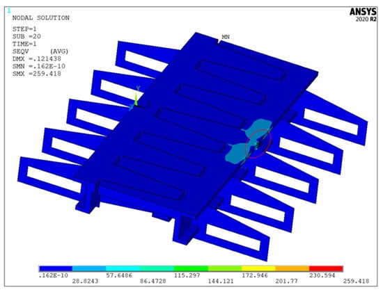
Figure 6.
Equivalent stress diagram of the structure under working condition I.
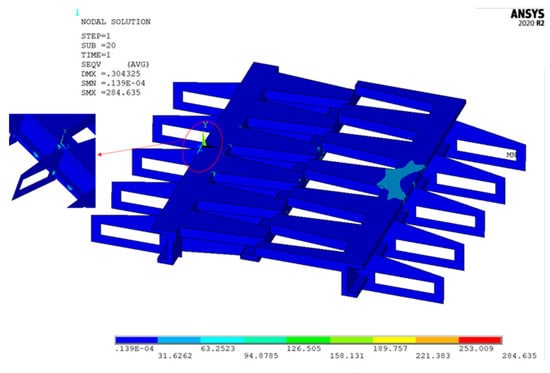
Figure 7.
Equivalent stress diagram of the structure under working condition II.
Table 2.
Results of the equivalent stress of the structure.
2.2.2. Deformation Evaluation under Working Conditions I and II by FEM
As illustrated by Figure 8, the maximum total deformation located on the middle finger of the moveable comb plate is 0.121 mm under working condition I. Furthermore, at the same position shown in Figure 9, the vertical deformation is 0.121 mm. Therefore, the detailed vertical deformation value of the expansion joint is summarized in Table 3.
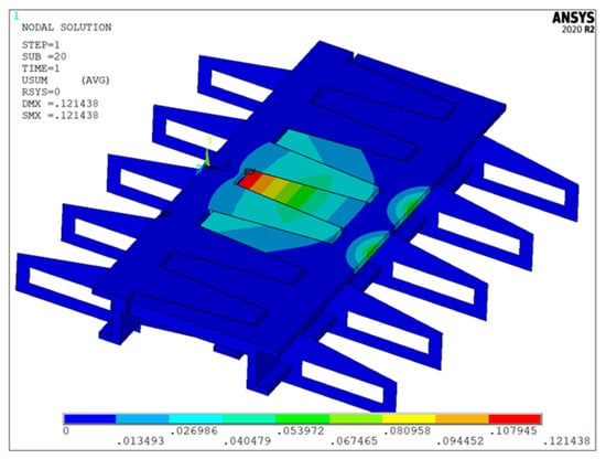
Figure 8.
Maximum total deformation diagram of the structure under the working condition I.
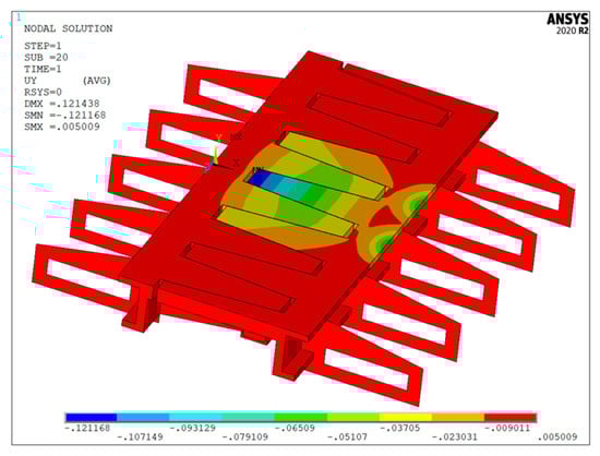
Figure 9.
Vertical deformation diagram of the structure under the working condition I.
Table 3.
Results of deformation of the structure under the working condition I.
As illustrated by Figure 10, the maximum total deformation located on the middle finger of the moveable comb plate is 0.304 mm under working condition II. Besides, at the same position as shown in Figure 11, the vertical deformation is 0.304 mm. Therefore, the detailed vertical deformation value of the expansion joint is summarized in Table 4.
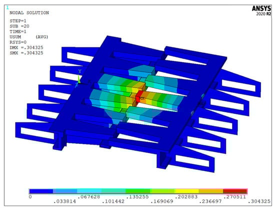
Figure 10.
Maximum total deformation diagram of the structure under the working condition II.
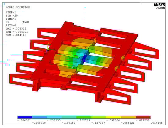
Figure 11.
Vertical deformation diagram of the structure under the working condition II.
Table 4.
Results of deformation of the structure under working condition II..
2.2.3. Shear Stress Evaluation under the Working Conditions I and II by FEM
Under working conditions, I, the maximum shear stress value of the comb plate expansion joint was 87.74 MPa, located at the connection between the fixed comb plate and the middle anchor, as shown in Figure 12. For working condition II, the maximum shear stress value of the comb plate expansion joint was 163.38 MPa, located at the connection between the fixed comb plate and the middle anchor, as represented in Figure 13. The maximum shear stress value under two working conditions is less than the permissible shear stress value of 204.97 MPa. Furthermore, the detailed shear stress value of the expansion joint is summarized in Table 5.
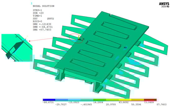
Figure 12.
Shear stress diagram of the structure under working condition I.
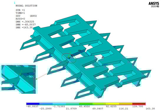
Figure 13.
Shear stress diagram of the structure under the working condition II.
Table 5.
Results of shear stress of the structure under two working conditions.
On top of that, the vertical deformation, equivalent stress, and shear stress of the new comb plate expansion joint under these two working conditions fulfilled the design requirements. Meanwhile, the maximum stress points and stress values under the two working conditions were found, and these results laid the foundation for fatigue life analysis.
2.3. Fatigue Life Prediction of the Comb Plate Expansion Joint via nCode DesignLife
nCode DesignLife is a fatigue analysis software with many functions [20,21,22,23,24]. Generally, software modules related to fatigue life, like nCode DesignLife, include geometric models, material parameters, load spectrum or load history, set-up of fatigue solution, and result display. To accurately predict the fatigue life of the comb plate expansion joint, the nCode DesignLife 2020 R2 analysis software [21,22] was adopted to predict the fatigue life of the comb plate expansion joint. It can provide a reference for strengthening the weak parts and guiding fatigue tests. The analysis flow chart is depicted in Figure 14.
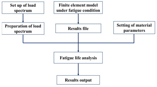
Figure 14.
Analysis flow chart.
The maximum opening amount of the comb plate bridge expansion device was taken as the fatigue test condition, and a vertical force of 43.30 kN was loaded at the solid element. The load on the expansion joint was calculated concerning the tyre’s contact area. The specific data is shown in Table 6.
Table 6.
Loading data of fatigue test.
As aforementioned above, working condition II was taken as the fatigue test condition, and the FEM is shown in Figure 15. The equivalent stress diagram of the structure under the fatigue working condition is shown in Figure 16. The resulting file (.rst) of the FEM of the comb plate expansion joint was imported into the FEInput module in nCode.
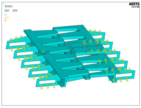
Figure 15.
FEM of the expansion joint under fatigue test condition.
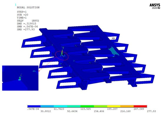
Figure 16.
Equivalent stress diagram of the structure under fatigue test condition.
Then, based on the load data of the fatigue test in Table 6, the TSGenerator module in nCode software generated the load spectrum shown in Figure 17. Thirdly, owing to the accumulation of damage caused by the external load, the comb plate expansion joint is prone to fatigue failure. Therefore, the S-N fatigue analysis method was determined, and the material properties of Q355 were selected in this module. Moreover, the SignedVonMises method was adopted to predict the fatigue life of the comb plate expansion joint. Von Mises Stress is a square of a sum of stress values squared. That way, Von Mises Stress is always positive. Using this parameter, it’s impossible to analyze if the body is undergoing tension or compression. Signed Von Mises Stress, in turn, considers the absolute value and the stress signal. Finally, the interface of the specific analysis process is shown in Figure 18.
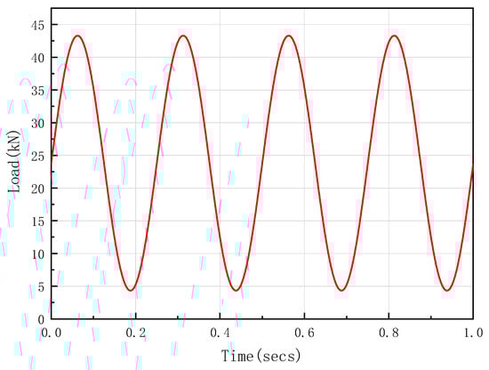
Figure 17.
Load spectrum for fatigue testing of the expansion joint.
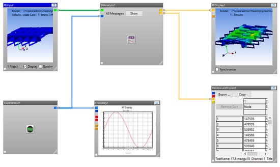
Figure 18.
The interface of fatigue analysis.
After calculation, the fatigue life of the comb plate expansion joint can be seen from the FEDisplay, as shown in Figure 19. The minimum life of the expansion device is times, which appears on the connection between the fixed plate and middle anchor and is higher than times stipulated by code [18]. The fatigue life of other components is shown in Table 7.
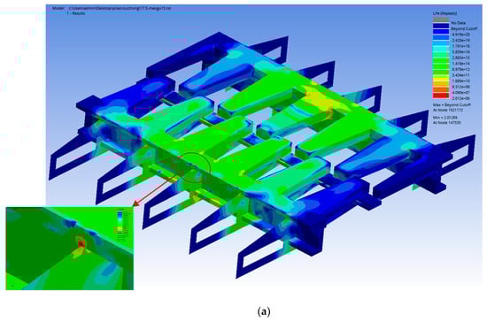
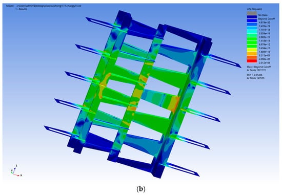
Figure 19.
The fatigue life of comb plate expansion joint:(a) View from the top, (b) View from the bottom.
Table 7.
Results of fatigue life the structure.
It should be noted that some areas have a shorter life span, such as the root of the movable comb plate and the contact surface between the fixed comb plate and the support system. Therefore, these areas also need to be carefully observed during the fatigue test on-site.
3. Tests for the Comb Plate Expansion Joint
3.1. Load-Bearing Tests
To verify whether the load-bearing capacity and deformation of the device can meet the code’s requirements, the load-bearing test of the comb-plate expansion device under working conditions II was carried out, and the relationship between the test load and the vertical deformation of the expansion device was derived. The results were compared with the simulation results to determine the validity of the finite element calculation. According to the standard JT/T 327-2016 [18], the limit state of the comb plate expansion device is that the device is in the 100% open position, i.e., the maximum stretch with a lap length larger than 10 mm, as shown in Figure 20a.
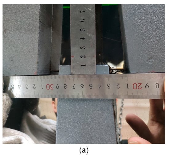
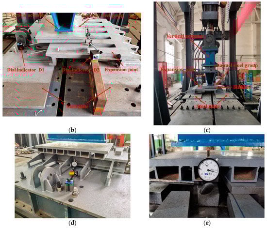
Figure 20.
The layout of tests: (a) Maximum opening state of the expansion device, (b) The set-up of the load-bearing test, (c) The layout of fatigue test, (d) Installation of Dial indicator D1, (e) Installation of Dial indicator D2.
The load-bearing test was carried out, as shown in Figure 20b. A channel set was installed below the vertical actuator to increase the loading area, and a tyre-like rubber plate measuring 245 mm × 200 mm × 20 mm was installed below the channel set to simulate the area of the wheel load. Dial indicator D1 and Dial indicator D2 were installed on the steel plate and the expansion device, respectively, as shown in Figure 20d,e. D1 was used to measure the deformation of the steel plate, and D2 to measure the total deformation of the steel plate and the comb plate expansion device. Under the same static load, the difference between the two scales is the deformation of the comb plate expansion.
The deformation of the expansion device was fitted to the test load data. The relationship between the loading force and deformation curve can be obtained as , where is the vertical deformation (mm), and is the loading force (kN). When the wheel load is 100 kN, the actual load on the steel structure of the comb plate expansion unit was 43.30 kN. According to the force-displacement curve, the vertical deformation of the comb-plate expansion is 0.339 mm. The error of the simulated vertical deformation is 10.38% compared to the test value, which proves the validity of the finite element model.
3.2. Bench Fatigue Test for the Full-Scale Specimens
A fatigue test was carried out to determine whether the fatigue life of the full-scale specimen of the comb plate expansion joint can fulfil 2 million times specified by industry code [18]. Meanwhile, the fatigue life predicted by nCode DesignLife can be verified.
The electro-hydraulic servo fatigue test system named PLS-1000 was used to conduct a fatigue test for the comb plate expansion joint. The maximum vertical load of this test machine is 1000 kN. The frequency can reach up to 20 Hz. The vertical loading head of this testing machine was used to simulate the effect of vehicle load on this device. First, a channel steel group was placed under the vertical loading head of the testing machine to enlarge the loading area, as shown in Figure 20c. Then, a rubber block with a dimension of 245 × 200 × 20 mm3 was laid up between the channel steel group and the expansion joint to simulate the contact area of the wheel. The fatigue load spectrum was performed by following the value listed in Table 6, and the cycle number is 2 million times, as shown in Figure 21.
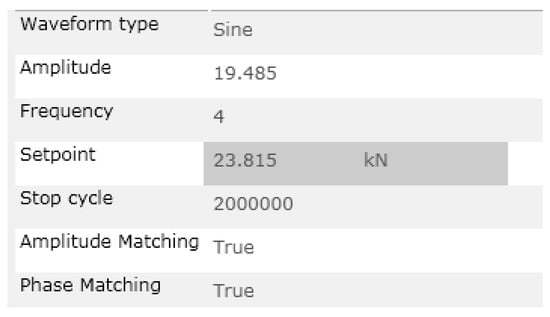
Figure 21.
Fatigue loading and cycle setting.
The variation range of the feedback signal of the loading force is 4.33~43.30 kN. After the bench fatigue test 2 million times, the detailed views of the comb plate expansion joint are displayed in Figure 22, Figure 23, Figure 24 and Figure 25. There were no cracks that appeared in the welds of the key components of the expansion device. The bolts connected the test bench, and the steel plates were scarcely loose.
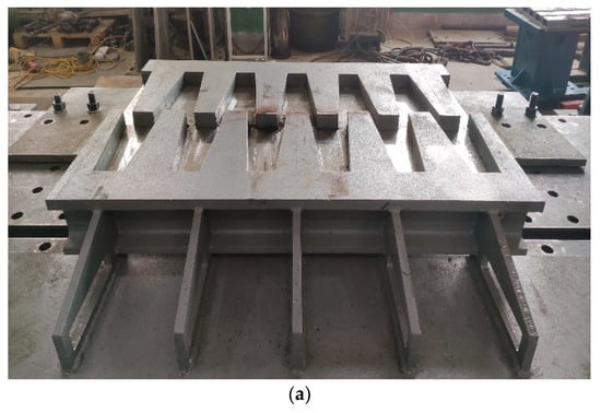
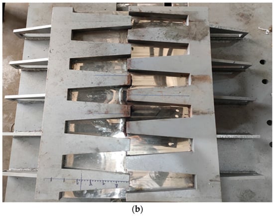
Figure 22.
The comb plate expansion joint after fatigue test: (a)The picture of the expansion joint from the main view, (b) The picture of the expansion joint from the top view.
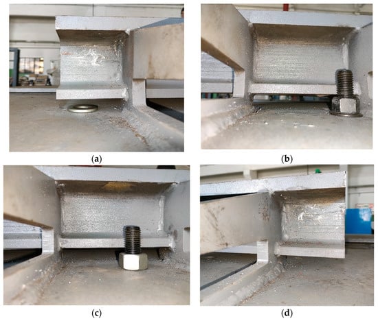
Figure 23.
Welds of fixed comb plate and anchor system: (a)At the top of Figure 22b, (b) At the third gap, (c) At the fourth gap, (d) At the bottom.
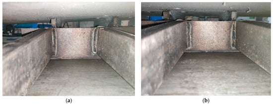
Figure 24.
Welds of fixed comb plate and support system:(a) From top to bottom in Figure 22b, below the third teeth, (b) Below the fourth teeth.
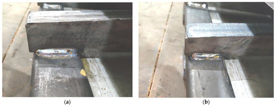
Figure 25.
Welds of steel groove and support system: (a) From top to bottom in Figure 22b, Below the third teeth, (b) Below the fourth teeth.
4. Conclusions
In this work, a new type of comb plate expansion joint was taken as the research object, with the merit of boltless as the loosening and failure of bolts have an intensively negative influence on the service of the bridge. To investigate the safety of this new type of expansion device, the equivalent stress, deformation, and shear stress were checked by Ansys software. Furthermore, nCode DesignLife software concerning fatigue life was adopted to predict the fatigue life of the expansion joint. The minimum life in the structure was recognized as the fatigue life of the entire device. In addition, the load-bearing test and bench fatigue test of the comb plate expansion joint were performed by code JT/T327-2016 [18]. The load-bearing test validates FEM developed in this work regarding the expansion joint. The fatigue test results show that the expansion joint was intact after 2 million cycles. The conclusions obtained in this work are as follows:
(1) The vertical deformation, equivalent stress, and shear stress of the new type of comb plate expansion joint under maximum and minimum openings fulfilled the design requirements. Meanwhile, the maximum stress points and stress values under the two working conditions were found, and these results laid the foundation for fatigue life analysis.
(2) The fatigue life of the device was assessed via nCode DesignLife, and the results show that the minimum value is 2.012 × 10⁶, which appears on the connection of the fixed comb plate and middle anchor. Moreover, the fatigue life obtained from simulation is higher than the 2 × 10⁶ times specified by the industry code, which meets the actual engineering demand. Additionally, the simulation results also give reference to the fatigue test on-site.
(3) To determine whether the fatigue life of the full-scale specimen of the comb plate expansion joint can fulfil 2 million times specified by industry code, a full-scale fatigue test was performed. There were no cracks that appeared in the welds of the key components of the expansion device after the bench fatigue test. Furthermore, the bolts used to connect the test bench to the steel plate were hardly loosened. Additionally, the test results prove the validity of the simulation results.
(4) The relationship between the loading force and deformation was obtained by the load-bearing test. The vertical deformation of the comb plate expansion device was 0.339 mm when the actual load on the steel structure of the comb plate expansion unit was 43.30 kN. The error in the simulated vertical deformation is 10.38% compared to the test value, which proves the validity of the finite element model.
It should be noted that to study the fatigue mechanism of expansion joints via fatigue simulation and full-scale fatigue test, the design duration can be significantly reduced, and the reliability of expansion joints can be improved affirmatively. However, there are some limitations in this paper. For instance, sinusoidal excitation was adopted to calculate the fatigue life of the comb plate expansion joint instead of actual vehicle excitation. Therefore, research in the future ought to consider the actual excitation of the car driving through the expansion joint. In this way, the fatigue life of a new expansion joint can be evaluated more accurately.
Author Contributions
Conceptualization, P.L. and Y.L.; methodology, Y.L.; software, Y.L.; validation, W.R., C.L. and J.W.; formal analysis, Y.L.; investigation, Y.L.; resources, P.L.; data curation, Y.L., W.R., C.L. and J.W.; writing—original draft preparation, Y.L.; writing—review and editing, P.L.; visualization, Y.L.; supervision, P.L.; project administration, P.L.; funding acquisition, P.L. All authors have read and agreed to the published version of the manuscript.
Funding
This project was supported by the National Natural Science Foundation of China (Grant No. 11902046), China Postdoctoral Science Foundation (Grant No. 2020M673580XB and 2016M602734), and the Shaanxi Postdoctoral Science Foundation Funded Project (Grant No. 2017BSHEDZZ67).
Data Availability Statement
Research data are not shared.
Conflicts of Interest
The authors declare that they have no known competing financial interests or personal relationships that could have appeared to influence the work reported in this paper.
References
- Chang, L.-M.; Lee, Y.-J. Evaluation of Performance of Bridge Deck Expansion Joints. J. Perform. Constr. Facil. 2002, 16, 3–9. [Google Scholar] [CrossRef]
- Lima, J.M.; de Brito, J. Management system for expansion joints of road bridges. Struct. Infrastruct. Eng. 2008, 6, 703–714. [Google Scholar] [CrossRef]
- Okuda, M.; Yumiyama, S.; Ikeda, H. Reinforcement of expansion joint on Akashi Kaikyo Bridge. In Proceedings of the JSCE 59th Annual Meeting, Japan Society of Civil Engineers, Tokyo, Japan, 20–22 October 2004. [Google Scholar]
- Sun, Z.; Zhang, Y. Failure Mechanism of Expansion Joints in a Suspension Bridge. J. Bridge Eng. 2016, 21, 05016005. [Google Scholar] [CrossRef]
- Guo, T.; Liu, J.; Zhang, Y.; Pan, S. Displacement Monitoring and Analysis of Expansion Joints of Long-Span Steel Bridges with Viscous Dampers. J. Bridge Eng. 2015, 20, 04014099. [Google Scholar] [CrossRef]
- Coelho, B.Z.; Vervuurt, A.; Peelen, W.; Leendertz, J. Dynamics of modular expansion joints: The Martinus Nijhoff Bridge. Eng. Struct. 2013, 48, 144–154. [Google Scholar] [CrossRef]
- Lima, J.M.; de Brito, J. Inspection survey of 150 expansion joints in road bridges. Eng. Struct. 2009, 31, 1077–1084. [Google Scholar] [CrossRef]
- Crocetti, R.; Edlund, B. Fatigue Performance of Modular Bridge Expansion Joints. J. Perform. Constr. Facil. 2003, 17, 167–176. [Google Scholar] [CrossRef]
- Wang, L.; Wang, Q.; Si, B. Experimental Research on fatigue testing of modular bridge expansion joint. China Civ. Eng. J. 2004, 37, 44–49. [Google Scholar]
- Artmont, F.A.; Roy, S. Evaluation of Bolted Single Support Bar Modular Bridge Joint Systems for Infinite Fatigue Life under Simulated Vehicular Loading. In Proceedings of the Structural Engineering: Providing Solutions to Global Challenges, Geneva, Switzerland, 23–25 September 2015. [Google Scholar] [CrossRef]
- Stamatopoulos, G.N. Fatigue life of the bolted yoke connection in single support beam (SSB) modular bridge expansion joints. Int. J. Steel Struct. 2017, 17, 723–738. [Google Scholar] [CrossRef]
- Zhang, T.; Zhong, X.; Yu, C. Dynamic characteristic analysis for Maurer bridge expansion joints. Chin. J. Appl. Mech. 2019, 36, 847–854. [Google Scholar]
- Chaallal, O.; Sieprawski, G.; Guizani, L. Fatigue performance of modular expansion joints for bridges. Can. J. Civ. Eng. 2006, 33, 921–932. [Google Scholar] [CrossRef]
- Guizani, L.; Bonnell, W.; Chaallal, O. Fatigue Testing and Performance of Welded Single-Support Bar Modular Bridge Joints. J. Bridge Eng. 2015, 20, 04014079. [Google Scholar] [CrossRef]
- Ma, Y.; Peng, A.; Wang, L.; Zhang, C.; Li, J.; Zhang, J. Fatigue performance of an innovative shallow-buried modular bridge expansion joint. Eng. Struct. 2020, 221, 111107. [Google Scholar] [CrossRef]
- Moor, G.; Hoffmann, S.; O’Suilleabhain, C. AASHTO Fatigue Testing of Modular Expansion Joints—Setting New Standards. In Sustainable Bridge Structures; Mahmoud, K., Ed.; CRC Press: Boca Raton, FL, USA, 2015; pp. 155–160. ISBN 978-0-429-22579-6. [Google Scholar]
- Roeder, C.W.; Hildahl, M.; Lund, J.A.V. Fatigue Cracking in Modular Bridge Expansion Joints. Transportation Research Record 1994. Available online: https://trid.trb.org/view/425266 (accessed on 1 March 2023).
- JT/T 327-2016; General Technical Requirements of Expansion and Contraction Installation for Highway Bridge. China Communications Press: Beijing, China, 2016.
- JTG D60-2015; General Specifications for Design of Highway Bridges and Culverts. China Communications Press: Beijing, China, 2015.
- Lu, L.; Yu, Y.; Zeng, G. Comparison and Analysis of Durability Life of Roller and Sliding Bearings Based on nCode Design-Life. J. Mech. Transm. 2017, 41, 114–119. [Google Scholar]
- Zhang, G.-X.; Niu, G.-G.; Guo, S.-S. Analysis of Fatigue Life of a Torsion Beam Based on nCode Design-Life. IOP Conf. Ser. Mater. Sci. Eng. 2018, 423, 012034. [Google Scholar] [CrossRef]
- Wu, N.; Wang, Y.; Wei, M. Fatigue Life Analysis of Driving Shaft of Conveyor System Based on nCode Design-Life. Int. Core J. Eng. 2019, 5, 174–179. [Google Scholar] [CrossRef]
- Lin, C.; Li, P.; Liu, W. Analysis and calculation of bending fatigue life of curveface gear. J. Braz. Soc. Mech. Sci. Eng. 2019, 42, 3. [Google Scholar] [CrossRef]
- Luo, H.; Li, Z.; Xiong, Q.; Jiang, A. Study on the wind-induced fatigue of heliostat based on the joint distribution of wind speed and direction. Sol. Energy 2020, 207, 668–682. [Google Scholar] [CrossRef]
Disclaimer/Publisher’s Note: The statements, opinions and data contained in all publications are solely those of the individual author(s) and contributor(s) and not of MDPI and/or the editor(s). MDPI and/or the editor(s) disclaim responsibility for any injury to people or property resulting from any ideas, methods, instructions or products referred to in the content. |
© 2023 by the authors. Licensee MDPI, Basel, Switzerland. This article is an open access article distributed under the terms and conditions of the Creative Commons Attribution (CC BY) license (https://creativecommons.org/licenses/by/4.0/).