Abstract
Over the past few decades, flux-switching permanent magnet (FSPM) machines have gained more attention. A novel flux-switching permanent magnet linear machine with a partitioned stator (FSPMLM-PS), which has the advantages of high thrust force density and high cost efficiency for short-stroke applications, is presented and analyzed in this article. Firstly, the twelve mover slots and seven stator poles (12s/7p) structure of FSPMLM-PS is introduced, and the fundamental principle of operation is investigated. The partitioned stator helps with the reduction in iron losses and the overall cost of the proposed FSPMLM-PS. One of the frequent issues in linear machines is the end effect, which is compensated for by setting assistant teeth at both ends of the mover. The proposed machine’s main design specifications are globally optimized through a multiobjective genetic optimization algorithm using JMAG software ver. 16.1, although the volumes of the PM and the magnetic and electric loadings are kept the same. The peak-to-peak flux linkage, thrust force, thrust ripples, and detent force are improved by 26.98%, 27.98%, 22.03%, and 68.33%, respectively, after optimization. The comparison results show that the proposed FSPMLM-PS is preferable to the conventional FSPMLM given in the literature. Under the same PM volume, the proposed machine provides 27.95% higher thrust force density.
1. Introduction
Modern tall buildings are required to have elevators. In skyscrapers, the ratio of the elevator hoistway to the entire floor area might reach 30% for traditional elevators propelled by rotary traction machines, which is obviously not cost-effective. Additionally, in order to ensure safety, the steel cable’s mass must be quite great in high buildings, which increases the power of the traction machine. The vertical vibration of the cable will also cause control problems. The ropeless elevator propelled by linear motors has been proposed to counter these problems [1,2].
Similar to rotary machines (RMs), linear machines (LMs) are electromechanical devices that convert electrical energy into mechanical energy and vice versa. LMs and RMs are highly similar in terms of construction [3,4,5]. With their numerous applications ranging from household to industrial, linear machines are in strong demand [6]. Because linear machines generate force along the x-axis with greater efficiency, reliability, and minimal energy consumption, they are preferable to rotary machines [7].
The linear induction machine (LIM) is a commonly used linear machine with a passive and simple stator structure [8]. However, because of the eddy effect, a poor power factor and efficiency are two of the definite disadvantages of LIM [9]. The advancement of permanent magnet (PM) materials and electronic power technologies has accelerated the development of permanent magnet linear motors [10,11]. Numerous PM linear machines in linear direct-drive systems have been established to meet the demand for the capability of high thrust force [12]. Linear permanent magnet machines have outstanding Electromagnetic performance, i.e., high efficiency and high thrust density [13]. Tubular permanent magnet linear machines can deliver high thrust density, but, due to the armature and PM, the mass increases, making the motor’s shaft likely to bend [14]. There are many different kinds of linear motors available these days, but the synchronous linear permanent magnet motor (SLPMM) is among the most popular motors because of its greater thrust force density and high acceleration properties [15,16,17,18].
Flux-switching linear permanent magnet machines synthesize the characteristics of synchronous linear permanent magnet machines (SLPMMs) and linear switched reluctance machines (LSRMs). The high power density and robust stator of the flux-switching linear permanent magnet machine make it an excellent candidate for high-speed applications [19,20]. Moreover, greater temperature regulation reduces the cost of production [21], which will make it resilient to challenging climatic conditions [22]. The flux switching permanent magnet linear motor (FSPMLM) is regarded as a revolution in the motor industry. Researchers are taking great interest and attention in FSPMLM due to its robust and vigorous stator structure, bipolar linkage of flux, high power density, and greater thrust force density [23,24].
In [13], a new FSPMLM was proposed with PMs and armature housed on the mover. The PMs were placed between the two U-shaped cores, which helps in balancing the magnetic circuit. However, the PMs are exposed to air which accounts for flux leakage, and the modular shape is a mechanically weak structure. Another modular double mover topology with a yokeless stator was proposed in [25], having the advantage of high thrust force density. Again, apart from the modular structure, the proposed design suffered from high detent force and thrust force ripples. In [26], the two PMs are connected with opposite polarity, sandwiching laminated steel between them. Constructing a mover pole was proposed, and the proposed design had high thrust force density; to minimize the detent force, a staggered stator and end PMs were used. However, the design used an enormous amount of PMs, and the overall structure was complex, making the machine’s manufacturing cost high.
In [27], an FSPMLM was presented as shown in Figure 1. Single-layer fractional-slot concentrated windings were implemented on the mover. The iron core teeth were categorized into two kinds: long teeth and short teeth. The windings were placed on the long teeth, while the PMs were housed on the short teeth. This arrangement resulted in a bipolar linkage flux, but the PMs were placed on the tip, which becomes a relatively weak mechanical structure, and there is a chance of falling off at high speeds. Based on the FSPMLM, a new topology is presented in this paper and is shown in Figure 2. In the proposed topology, the PMs are shifted and sandwiched between stator pieces. This helps in the separation of the armature winding from the PMs; also, the usage of iron in the stator part is reduced, which, in turn, minimizes iron losses and hence improves efficiency.
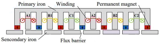
Figure 1.
Conventional FSPMLM.
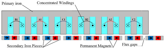
Figure 2.
Proposed FSPMLM-PS.
The rest of the sections in the paper are ordered as follows: the topology of the machine and operational principle are covered in Section 2. Furthermore, the FSPML machines with various winding configurations are analyzed and compared. The genetic optimization is covered in Section 3. The electromagnetic performance analysis is overviewed in Section 4. Suppression of unbalanced flux linkage is presented in Section 5. The comparison with regular design is focused on in Section 6. Section 7 is dedicated to conclusions.
2. Topology and Operating Principle of FSPMLM-PS
2.1. Topology
The proposed 7p/12s machine is shown in Figure 2 and has a simple mover and partitioned stator. The gaps in the stator pieces help in attaining the bipolar flux linkage. A three-phase concentrated winding is employed on the iron tooth of the mover. Two coil sets comprise one phase. Auxillary teeth are embedded at the ends of the mover to balance the three-phase magnetic flux. In the proposed topology, the mover only carries the armature excitation windings, while the stator contains the inset PMs. The PMs are shifted from the mover and sandwiched between the stator pieces, making them cylindrical. The separation of the PMs and the armature excitation helps with proper heat distribution. Furthermore, the usage of iron in the stator part is reduced, ultimately reducing iron core losses. The important parameters for geometry are listed in Table 1 and illustrated in Figure 3.

Table 1.
Parameters for geometry of FSPMLM-PS.
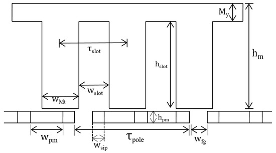
Figure 3.
Parameters for geometry of proposed FSPMLM-PS.
2.2. Operating Principle
The suggested novel FSPMLM-PS’s operating principle is presented using a simple model, as illustrated in Figure 4. At positions ‘a’ and ‘c’, the magnetic flux does not pass through the iron core tooth, so, at points ‘a’ and ‘c’, the flux is zero. When a stator iron core and a mover iron tooth are in the relative positions depicted in Figure 4b,d, the coil flux-linkage reaches its maximum positive value at point ‘b’ and its maximum negative value at point ‘d’, as shown in Figure 5. The coil flux-linkage changes a cycle when the mover, the primary component of the machine, moves one pole pitch of the stator. The cycle repeats itself due to symmetry.
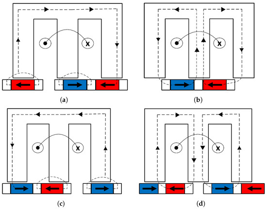
Figure 4.
Operating principle of FSPMLM-PS: (a) primary at position ‘a’, (b) primary at position ‘b’, (c) primary at position ‘c’, and (d) primary at position ‘d’.
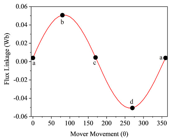
Figure 5.
Single-phase flux linkage at no-load.
3. Genetic Optimization
Today’s genetic algorithms comprise the effective global optimization methods family used to solve the complex real-life problems that ascend in science and technology. They can investigate enormous data sets despite their computational complexity. In order to solve optimization-related issues, this procedure is frequently implemented in order to produce valuable solutions. Genetic optimization is independent of the starting point of the search; thus, it is least likely to become stuck in local minima. It also requires no trivial knowledge of the objective function or constraint function.
JMAG software has in-built multiobjective genetic optimization (GO), and the proposed design employed GO to enhance the foremost CAD variables of the proposed machine. The complete GO flowchart is illustrated in Figure 6. Improving the average thrust force () and reducing thrust force ripples () were the primary goals of this optimization.
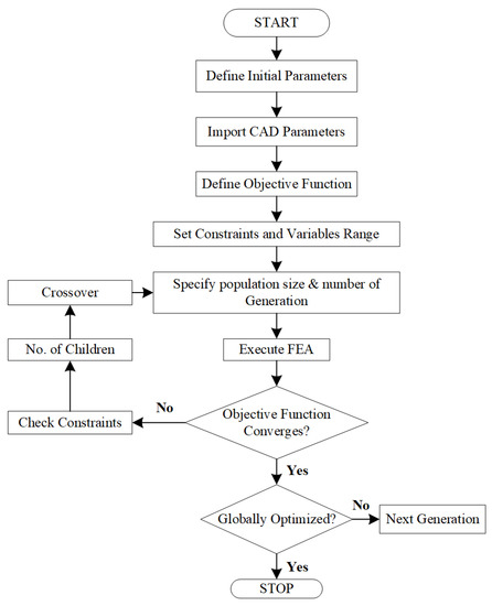
Figure 6.
The genetic optimization’s execution steps.
In Equations (1) and (2), the objective function and constraints of this GO are expressed correspondingly. The primary objective of employing this genetic algorithm is to maximize the but minimize the . The initial design is created in the geometry editor and then brought into the designer window. In Table 2, the ranges of the geometry parameters, selected for optimization, are listed. Afterward, the simulation of a total of 438 cases was conducted across several generations; the number of children, the population size, and the genetic optimization converged to achieve a global value of the objective function and an optimized structure of the proposed design. The genetic optimization was performed on an HAIER-PC 64-bit operating system with 8 GB RAM, Intel(R), Core(TM) m3-7Y30 CPU running at 1.00 GHz and took 11 h and 20 min; it occupied 7.8 GBs space on the drive.
Table 2.
Ranges of varying geometry parameters.
During the genetic optimization, the total number of cases simulated are plotted against the and in Figure 7. The figure reveals that, after genetic optimization, a maximum thrust force value of 338.5N was obtained. The average thrust force and the thrust force ripples with respect to various geometry variables are shown in Figure 8. A comparison of the performance after genetic optimization is provided in Table 3.
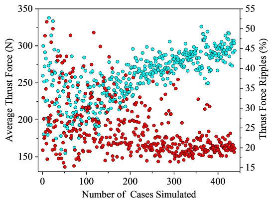
Figure 7.
and for each case simulated.

Figure 8.
and for (a) slot area, (b) mover yoke height, (c) mover tooth width, (d) stator height, (e) PM area, and (f) flux gap.
Table 3.
Comparison of performance after genetic optimization.
4. Electromagnetic Performance of FSPMLM-PS
4.1. Flux Linkage
The flux linkage at no-load is remarkably enhanced after the genetic optimization, as illustrated in Figure 9a. All of the three-phase flux linkage is bipolar, balanced, and sinusoidal. Because of the auxiliary tooth’s addition and the concentrated windings, there is no end-effect issue. After genetic optimization, the peak-to-peak value of the flux is improved to 0.116699 Wb; it was 0.09189 Wb in the initial design. The optimized design’s harmonics are plotted with yellow, blue, and indigo colors for the three phases, and the three phases of the initial design’s harmonics are shown in orange, green, and purple, respectively; these are plotted in Figure 9b.
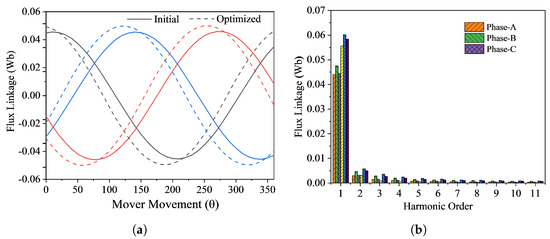
Figure 9.
(a) Flux linkage and (b) harmonics of the proposed FSPMLM-PS.
4.2. Back-EMF
After the genetic optimization, the proposed design’s back-EMF is efficiently increased. With a rated velocity of 2 m/s, in Figure 10, the back-EMF of the proposed FSPMLM-PS is depicted. The back-EMF’s peak-to-peak value increases to 63.07 V after the GO; it was 46.40 V before the optimization. In the Figure 10, the solid line shows the initial design, and the dotted line shows the optimized one.
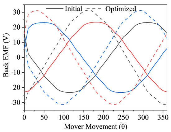
Figure 10.
Back-EMF of the proposed FSPMLM-PS.
4.3. Air-Gap Flux Density
The air-gap flux density measures the magnetic field strength inside a machine’s air-gap. A better machine performance can arise due to a stronger magnetic field, which specifies a higher air-gap flux density. The magnetic flux densities along the x-axis and y-axis before and after the genetic optimization are shown in Figure 11.
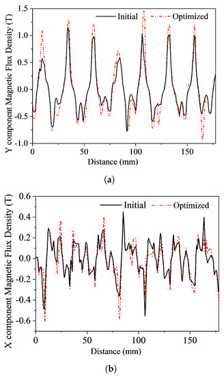
Figure 11.
Air-gap flux density: (a) Y component (b) X component.
4.4. Flux Distribution
The flux is dispersed evenly across the machine, as presented in Figure 12. This explains the operating principle discussed in Section 2, and the flux distribution verifies it.
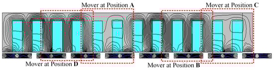
Figure 12.
Flux distribution of the proposed FSPMLM-PS.
4.5. Detent Force
For the proposed FSPMLM-PS, the detent force is produced on a no-load analysis by the attraction between the excitation sources on the mover and the stator’s body. Noise and vibration are caused by this undesirable force. The vibration and noise will increase if there is a stronger attraction between the mover’s excitation and the stator’s core. Figure 13 shows the detent or cogging force of the presented FSPMLM-PS’s initial design and optimized design.
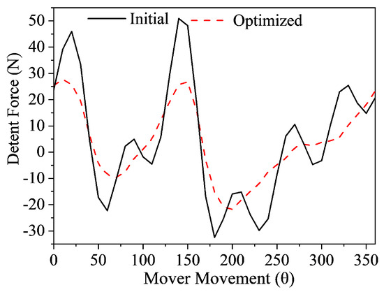
Figure 13.
Detent force of the proposed FSPMLM-PS.
4.6. Thrust Force
The primary performance assessment for the linear machine is the thrust force, and, during a machine design, the main goal is thrust force improvement. Initially, the thrust force of the presented FSPMLM-PS was 264.49N. After the genetic optimization, the thrust force improved to 338.50 N, which is 27.98% greater than the FSPMLM presented in literature [12]. In the optimized thrust force, the ripples are also reduced by 22.03%, as shown in Figure 14.
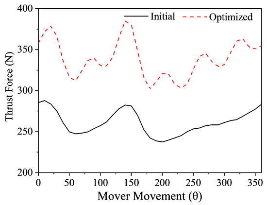
Figure 14.
Thrust force of the proposed FSPMLM-PS.
4.7. Analysis of Efficiency of the FSPMLM-PS
In this section, the technique illustrated in [28] is used to attain the performance characteristics of the presented design. In Figure 15, curves for the force velocity and power velocity are presented. The FSPMLM-PS that is being proposed has a higher of 338.50 N, and the output power is 4450.041 W at 13.15 m/s speed. As force and velocity have an inverse relation, keeping the output power constant, the thrust force will decrease by increasing the velocity. In linear machines, the product of the speed and gives the output power. In the same way, the sum of the total losses and the output power is equal to the input power.
where
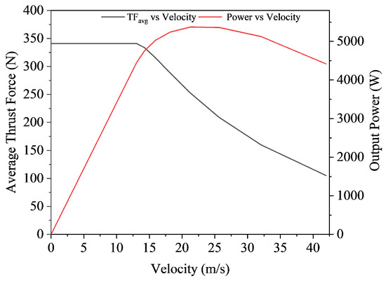
Figure 15.
Force vs. velocity and power vs. velocity graph.
The iron losses are calculated using JMAG. To calculate the copper losses, Equation (5) is utilized. As the speed is its minimum and the electric loading is at its maximum, the copper losses (172.27 W) are higher, the iron losses are 80.96 W, and the PM losses are 33.30 W.
4.8. Analysis of Losses
Different losses, such as copper, iron, and eddy current losses, are taken into account, and their impact on efficiency is observed and tabulated in Table 4.
where represents the copper losses, I is the current, is the resistivity of the material, J is the current density of the machine, L is the length of wire, N is the number of turns per coil, and Q is the number of slot pairs in the mover.
Table 4.
Effect of PM losses on performance.
5. Suppression of Unbalance Linkage of Flux
For the proposed FSPMLM-PS, the end PMs generated the magnetic field, which can pass across the mover’s iron core teeth on both ends. Consequently, for three-phase concentrated windings, a major problem will be the linkage of the flux imbalance [29,30]. For the 12s/7p FSPMLM-PS investigated in this paper, the three-phase imbalanced linkage of the flux results in an additional thrust fluctuation that degrades the motor performance and increases trouble in the machine control. The proposed design includes assistant or auxiliary teeth at both ends of the mover, as shown in Figure 16, which is presented to overcome the three-phase imbalanced linkage of the flux. The assistant or auxiliary slots and teeth specifications are exactly the same as those of the other slots and teeth of the machine.
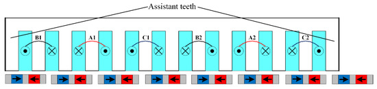
Figure 16.
FSPMLM-PS with assistant teeth at the both ends of mover.
6. Comparison with Traditional Design
Lastly, the proposed FSPMLM-PS is compared to the conventional design [27]. The leading dimensions of both the topologies and the magnetic material type are kept the same. The results of the comparison are shown in Table 5. The conventional and proposed designs use partitioned stators, keeping the current value, the volume of the PM, and the number of turns constant. The inset PM scheme opted for the proposed design while achieving a superior performance to that of the traditional design. Furthermore, the presented design reduced the stator’s volume, and this factor reduced the cost of the machine.
Table 5.
Comparison with conventional design.
The proposed FSPMLM-PS is also compared with the surface-mounted PM linear motors proposed in the literature [31]. In [31], two motors are compared with surface-mounted PMs on a stator and another with a consequent pole stator structure and an inset PM in a mover yoke. The proposed and the conventional designs possess different dimensions; therefore, for a fair comparison, the machines are compared based on the thrust force per PM volume. Table 6 reveals that the proposed machine uses less PM volume and offers a reasonable thrust force per PM volume compared to the conventional designs.
Table 6.
Comparison with surface-mounted PM linear motors.
7. Conclusions
In this article, the three-phase flux-switching permanent magnet linear machine with a partitioned stator (FSPMLM-PS) is proposed and analyzed. The proposed FSPMLM-PS possesses the feature of high thrust density of permanent magnet machines. The presented machine employed single-tooth concentrated windings, thus minimizing copper losses. Auxiliary teeth were added at both endpoints of the mover; they fulfill their purpose and provide a path for the leakage flux from the ends of the primary component. JMAG’s built-in multiobjective genetic optimization algorithm is employed to improve and optimize machine-design specifications globally. An electromagnetic performance analysis of the machine is carried out to determine the machine’s performance. The performance comparison between the conventional and the proposed design shows the supremacy of the proposed design over the presented design in the literature. In conclusion, when compared with the conventional FSPMLM, the proposed FSPMLM-PS possesses greater thrust density and a lesser stator weight at the same time. The proposed FSPMLM-PS has vast prospects in short-stroke applications such as escalators, ropeless elevators, etc. The authors intend to work on the modeling, thermal analysis, and prototyping of the proposed design in the future.
Author Contributions
Conceptualization, S.T. and B.U.; methodology, S.T. and B.U.; software, S.T., B.U. and N.M.; validation, S.T., B.U. and N.M.; resources, F.K. and B.A.; original draft preparation, S.T. and N.M.; review and editing, B.U. and F.K.; supervision, F.K.; project administration, F.K. and B.A.; formal analysis, B.A., funding acquisition, B.A. All authors have read and agreed to the published version of the manuscript.
Funding
This research work was funded by Institutional Fund Projects under grant no. IFPIP: 894-135-1443. The authors gratefully acknowledge the technical and financial support provided by the Ministry of Education and King Abdulaziz University, DSR, Jeddah, Saudi Arabia.
Data Availability Statement
Not applicable.
Conflicts of Interest
The authors declare no conflict of interest.
Abbreviations
| Back-EMF | Back-electromotive force |
| FSPM | Flux-switching permanent magnet |
| FSPMLM-PS | FSPM linear machine with a partitioned stator |
| GO | Genetic optimization |
| LM | Linear machine |
| LIM | Linear induction machine |
| LSRMs | Linear switched reluctance machines |
| PM | Permanent magnet |
| RM | Rotary machine |
| SLPMM | Synchronous linear permanent magnet motor |
| Average thrust force | |
| Thrust force ripples | |
| TFD | Thrust force density |
| THD | Total harmonic distortion |
References
- Ishii, T. Elevators for skyscrapers. IEEE Spectr. 1994, 31, 42–46. [Google Scholar] [CrossRef]
- Elevator World. Linear-motor driven vertical transportation system. Elev. World 1996, 44, 66–73. [Google Scholar]
- Boldea, I. Linear Electric Machines, Drives, and MAGLEVs Handbook, 1st ed.; CRC Press: Boca Raton, FL, USA, 2013. [Google Scholar]
- Eguren, I.; Almandoz, G.; Egea, A.; Ugalde, G.; Escalada, A.J. Linear machines for long stroke applications—A review. IEEE Access 2019, 8, 3960–3979. [Google Scholar] [CrossRef]
- Hellinger, R.; Mnich, P. Linear motor-powered transportation: History, present status, and future outlook. Proc. IEEE 2009, 97, 1892–1900. [Google Scholar] [CrossRef]
- Kou, B.; Luo, J.; Yang, X.; Zhang, L. Modeling and analysis of a novel transverse-flux flux-reversal linear motor for long-stroke application. IEEE Trans. Ind. Electron. 2016, 63, 6238–6248. [Google Scholar] [CrossRef]
- Ullah, B.; Khan, F.; Milyani, A.H. Analysis of a Discrete Stator Hybrid Excited Flux Switching Linear Machine. IEEE Access 2022, 10, 8140–8150. [Google Scholar] [CrossRef]
- Abdollahi, S.E.; Mirzayee, M.; Mirsalim, M. Design and analysis of a double-sided linear induction motor for transportation. IEEE Trans. Magn. 2015, 51, 1–7. [Google Scholar] [CrossRef]
- Li, J.; Li, W.; Li, R.; Ming, Z. A five-phase doubly fed doubly salient HTS linear motor for vertical transportation. IEEE Trans. Appl. Supercond. 2018, 28, 1–5. [Google Scholar] [CrossRef]
- Thornton, R.; Thompson, M.T.; Perreault, B.M.; Fang, J. Linear motor powered transportation [Scanning the Issue]. Proc. IEEE 2009, 97, 1754–1757. [Google Scholar] [CrossRef]
- Stumberger, G.; Aydemir, M.T.; Zarko, D.; Lipo, T.A. Design of a linear bulk superconductor magnet synchronous motor for electromagnetic aircraft launch systems. IEEE Trans. Appl. Supercond. 2004, 14, 54–62. [Google Scholar] [CrossRef]
- Zhao, W.; Ma, A.; Ji, J.; Chen, X.; Yao, T. Multiobjective optimization of a double-side linear Vernier PM motor using response surface method and differential evolution. IEEE Trans. Ind. Electron. 2019, 67, 80–90. [Google Scholar] [CrossRef]
- Zhao, J.; Mou, Q.; Guo, K.; Liu, X.; Li, J.; Guo, Y. Reduction of the detent force in a flux-switching permanent magnet linear motor. IEEE Trans. Energy Convers. 2019, 34, 1695–1705. [Google Scholar] [CrossRef]
- Yu, W.; Yang, G.; Li, Z.; Wang, D.; Wang, X. A tubular linear motor structure suitable for large thrust. J. Mech. Sci. Technol. 2021, 35, 4987–4995. [Google Scholar] [CrossRef]
- Zhang, B.; Cheng, M.; Wang, J.; Zhu, S. Optimization and analysis of a yokeless linear flux-switching permanent magnet machine with high thrust density. IEEE Trans. Magn. 2015, 51, 1–4. [Google Scholar] [CrossRef]
- Huang, L.; Chen, Y.; Kong, H.; Lu, Q.; Ye, Y. Analysis of a permanent magnet linear synchronous motor with segmented armature for transportation system. In Proceedings of the 2014 17th International Conference on Electrical Machines and Systems (ICEMS), Hangzhou, China, 22–25 October 2014; pp. 1791–1796. [Google Scholar]
- Kwon, Y.S.; Kim, W.J. Detent-force minimization of double-sided interior permanent-magnet flat linear brushless motor. IEEE Trans. Magn. 2015, 52, 1–9. [Google Scholar] [CrossRef]
- Wang, H.; Li, J.; Qu, R.; Lai, J.; Huang, H.; Liu, H. Study on high efficiency permanent magnet linear synchronous motor for maglev. IEEE Trans. Appl. Supercond. 2018, 28, 1–5. [Google Scholar] [CrossRef]
- Ullah, B.; Khan, F.; Hussain, S.; Khan, B. Modelling, Optimization and Analysis of Segmented Stator Flux Switching Linear Hybrid Excited Machine for Electric Power Train. IEEE Trans. Transp. Electrif. 2022, 8, 3546–3553. [Google Scholar] [CrossRef]
- Xiao, F.; Liu, X.; Du, Y.; Shi, K.; Xu, P. A C-core linear flux-switching permanent magnet machine with positive additional teeth. In Proceedings of the 2014 17th International Conference on Electrical Machines and Systems (ICEMS), Hangzhou, China, 22–25 October 2014; pp. 1757–1761. [Google Scholar]
- Hwang, C.C.; Li, P.L.; Liu, C.T. Design and analysis of a novel hybrid excited linear flux switching permanent magnet motor. IEEE Trans. Magn. 2012, 48, 2969–2972. [Google Scholar] [CrossRef]
- Dubois, M.R.; Polinder, H.; Ferreira, J.A. Magnet shaping for minimal magnet volume in machines. IEEE Trans. Magn. 2002, 38, 2985–2987. [Google Scholar] [CrossRef]
- Ullah, B.; Khan, F.; Qasim, M.; Jan, H.U.; Khan, B.; Khalid, S. Design and analysis of consequent pole dual stator hybrid excited linear flux switching machine for rail transit system. In Proceedings of the 2021 International Conference on Emerging Power Technologies (ICEPT), Topi, Pakistan, 10–11 April 2021; pp. 1–6. [Google Scholar]
- Ullah, N.; Khan, M.K.; Khan, F.; Basit, A.; Ullah, W.; Ahmad, T.; Ahmad, N. Comparison of analytical methodologies for analysis of single sided linear permanent magnet flux switching machine: No-load operation. Appl. Comput. Electromagn. Soc. J. (ACES) 2018, 33, 923–930. [Google Scholar]
- Cao, R.; Shen, D.; Hua, W. Research on detent force characteristics of a linear flux-switching permanent-magnet motor. IEEE Trans. Energy Convers. 2021, 36, 2998–3006. [Google Scholar] [CrossRef]
- Hao, W.; Wang, Y. Analysis of double-sided sandwiched linear flux-switching permanent-magnet machines with staggered stator teeth for urban rail transit. IET Electr. Syst. Transp. 2018, 8, 175–181. [Google Scholar] [CrossRef]
- Tan, Q.; Wang, M.; Li, L. Analysis of a new flux switching permanent magnet linear motor. IEEE Trans. Magn. 2020, 57, 1–5. [Google Scholar] [CrossRef]
- Qi, G.; Chen, J.T.; Zhu, Z.Q.; Howe, D.; Zhou, L.B.; Gu, C.L. Influence of skew and cross-coupling on flux-weakening performance of permanent-magnet brushless AC machines. IEEE Trans. Magn. 2009, 45, 2110–2117. [Google Scholar] [CrossRef]
- Huang, X.Z.; Yu, H.C.; Zhou, B.; Li, L.Y.; Gerada, D.; Gerada, C.; Qian, Z.Y. Detent-force minimization of double-sided permanent magnet linear synchronous motor by shifting one of the primary components. IEEE Trans. Ind. Electron. 2019, 67, 180–191. [Google Scholar] [CrossRef]
- Huang, X.; Ji, T.; Li, L.; Zhou, B.; Zhang, Z.; Gerada, D.; Gerada, C. Detent force, thrust, and normal force of the short-primary double-sided permanent magnet linear synchronous motor with slot-shift structure. IEEE Trans. Energy Convers. 2019, 34, 1411–1421. [Google Scholar] [CrossRef]
- Deng, C.; Ye, C.; Yang, J.; Sun, S.; Yu, D. A novel permanent magnet linear motor for the application of electromagnetic launch system. IEEE Trans. Appl. Supercond. 2020, 30, 1–5. [Google Scholar] [CrossRef]
Disclaimer/Publisher’s Note: The statements, opinions and data contained in all publications are solely those of the individual author(s) and contributor(s) and not of MDPI and/or the editor(s). MDPI and/or the editor(s) disclaim responsibility for any injury to people or property resulting from any ideas, methods, instructions or products referred to in the content. |
© 2023 by the authors. Licensee MDPI, Basel, Switzerland. This article is an open access article distributed under the terms and conditions of the Creative Commons Attribution (CC BY) license (https://creativecommons.org/licenses/by/4.0/).