Abstract
This paper introduces and analyzes the power losses of a five-phase drive system based on an indirect matrix converter (IMC) and a five-phase synchronous reluctance motor (SynRM). The different loss components in the power converter and the motor have been discussed and analyzed. Moreover, a control strategy is applied to decrease the power converter losses and make the system superior to the conventional one. The carrier-based pulse-width-modulation (CBPWM) method is used for this. Through the CBPWM, switching losses are kept as low as possible in this technique by ensuring that the rectifier stage experiences zero current commutation. To achieve this, the rectifier and inverter stages are synchronized so that the commutation in the rectifier stage occurs at the zero vectors of the inverter, which corresponds to a zero DC-link current. The converter will therefore have less switching losses thanks to the rectifier’s null value. Experimental validation has shown the usefulness of the proposed CBPWM in providing lower switching losses in the IMC. Additionally, a comparison of the proposed drive system’s performance with a traditional three-phase SynRM-based inverter will be carried out in the speed and torque control modes.
1. Introduction
The latest growth of electric motor applications justifies the need to improve their working efficiency [1,2,3]. The induction machine has been adopted in industries despite having a lower efficiency, because of being more readily available and less expensive [4]. Three-phase permanent magnet motors are now very common because they are more efficient than conventional electric motors [5]. Several design and control strategies for inverter-fed three-phase interior permanent synchronous motors (IPMSMs) have been studied in the literature [6,7]. However, due to the rising influence of harmonics, the inverter and core losses are noticeable at higher speeds, significantly reducing the drive system’s efficiency. The magnet size has been eliminated in three-phase synchronous reluctance motors (SynRMs) [8,9]. Hence, the efficiency of these machines is increased and the rise in the temperature becomes lower compared to induction machines and IPMSMs. However, SynRMs have a poor power factor. The power factor and the performance of SynRMs can be improved by adding a cheaper and small ferrite magnet in their rotor producing permanent magnet-assisted synchronous reluctance motors (PMa-SynRMs). In low-cost integrated motor drive systems with a wider constant power speed range, these motors have been recommended [8]. Furthermore, because of the smaller magnet size, both the core loss and the magnet loss are reduced. Such high-performance motors are used in other industries as well, particularly in electric and hybrid vehicle applications [9]. When selecting the type of motor to utilize for long-term operation, efficiency is the important performance measure. As a result, in order for the system to work as effectively as possible, the total losses and the torque density must be identified.
An easy and effective way to increase efficiency is to increase the number of phases. This method can be applied to switched reluctance machines, induction machines, and SynRMs. In addition to reducing torque ripple, multiphase machines (machines with a phase number of m > 3) also offer larger torque densities and better fault tolerance capabilities than traditional three-phase machines. Regarding the best configuration for a multiphase system in terms of design and control, five-phase systems are regarded as an excellent option [10,11,12]. These motors are an excellent option because of their improved torque-speed characteristics, greater torque density, decreased torque ripple, increased dependability, and lower size compared to other multiphase machines, e.g., six- and seven-phase machines. The efficiency of the whole five-phase motor drive must be justified in contrast to a three-phase design with the same rated power, even if five-phase machines are more fault tolerant. Multiphase drive systems are required to be reliable, particularly in adverse situations where ambient temperatures can soar dangerously high and maintenance and the replacement of damaged components are challenging to come by. The traditional rectifier inverter is used by the majority of multiphase driving systems [13,14,15]. Unfortunately, this converter has a large DC-link capacitor that can be a system fatality and has to be replaced or repaired, especially at higher temperatures. To address this issue, matrix converters (MC) were utilized as they do not require the typical converters’ DC-bus capacitors [16,17]. Hence, in this paper, an MC will be used to control the currents of the five-phase SynRM. This drive system is not introduced before and can be considered a reliable and improved drive system.
Direct and indirect MC are two of the numerous types of MC that are available. Although, the direct architecture necessitates a large number of power switches, multistep commutation techniques, and complex overvoltage safety circuits. The IMC structure is built using an AC-to-DC-to-AC power conversion; a large capacitor is not utilized in the center. According to Figure 1, the IMC is separated into two stages: the rectifier stage and the inverter stage. The maximum voltage-transfer-ratio value and the input/output characteristics are the same for the DMC and IMC topologies. Contrarily, the DMC topology does not permit soft switching commutation but the IMC architecture does [18,19,20,21,22,23]. Consequently, the indirect topology of the MC will be used in the proposed drive system in this paper.
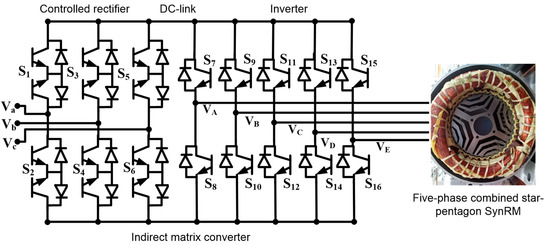
Figure 1.
Five-phase SynRM drive system based on indirect MC.
The control technique is a crucial factor that must be taken into account while designing the drive system. The efficiency and reliability of the drive system are greatly affected by the control strategy. In the literature, several control strategies have been proposed [19,20,21,22]. Researchers have recently applied the carrier-based PWM (CBPWM) method to streamline the space-vector PWM (SVPWM) [22]. The main contribution in [22] was on the simple clamping circuit and its startup issues and how to solve these issues. The load in [22] was a five-phase static R-L load. In this manuscript, the load is a five-phase rewound SynRM with combined star–pentagon winding. The introduced drive system in this paper has not been introduced before. Although, the control method in [22] is applied in this paper to control the five-phase SynRM. This method is not investigated and validated before in terms of lower switching loss. Hence, the main focus of this paper is the dynamic validation of the CBPWM for the proposed drive system. This research attempts a study the electrical losses observed in an MC-fed five-phase SynRM. This drive system is researched and compared with regard to various losses, including switching losses, conduction losses, winding, and core losses. The main focus will be on the rectifier losses to prove the effectiveness of the proposed CBPWM in providing zero switching losses in the rectifier stage. The validity of these assertions has been tested experimentally. Moreover, the performance of the proposed drive system will be studied at speed and torque control modes with a comparison of the conventional three-phase SynRM-based inverter.
2. Indirect Matrix Converter
Figure 1 depicts the power circuit design of the proposed three-to-five-phase IMC. It consists of a five-phase inverter stage and a controlled rectifier stage. In contrast to the inverter stage, which only requires ten unidirectional switches, the rectifier stage uses six bidirectional switches. The goal of the rectifier stage is to generate sinusoidal input currents while maintaining a positive DC-link voltage. A five-phase output voltage with changeable magnitude and frequency is produced by the five-phase inverter stage. The indirect SVM study showed that a challenging process may be used to construct the SVM for the five-phase indirect MC [22]. The choice of the operating vectors is made individually in the rectifier and inverter stages. The duty ratios of the effective vectors in the rectifier and inverter stages are calculated using several complicated formulae. The switching states of the rectifier and inverter stages are then coordinated to create balanced output voltages and to validate zero current commutation in the rectifier stage. In order to address these problems, the CBPWM approach was developed. It makes it straightforward to generate gating pulses for the rectifier and the inverter. Hence, in this paper, the operating principles of the proposed IMC topology are described using the CBPWM instead of the well-known theory of the indirect SVM.
2.1. Controlled Rectifier
As seen in Figure 1, there are six bidirectional switches in the rectifier stage. The bidirectional switches in the rectifier stage are made up of two common emitters unidirectional switches because there are no bidirectional switches available on the market. Equation (1) may be used to explain the input voltage to the controlled rectifier stage (1). In (1), stands for the number of the input phase, such as a, b, or c. The frequency and the maximum phase input voltage are represented by the variables , in (1). The values of in (1) are 0, 1, and 2. To avoid a virtual DC connection open circuit, these switches can only be in nine switching states. According to the hexagon in Figure 2, these switching states are composed of three zero vectors (() and six nonzero (active) vectors (). The blue-colored vectors in Figure 2 are used to calculate the duty cycles for both zero and active vectors, as illustrated in Equations (2)–(4) [22]. In (2)–(4), , which has a value between 0 and 1, is the input current modulation index. Additionally, denotes the angle to the rectifier’s input reference current vector (). measured starting from the positive X-axis.
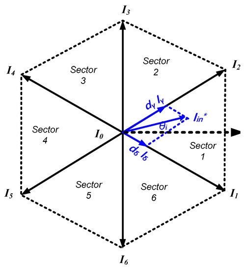
Figure 2.
The hexagon of the controlled rectifier.
In order to get the highest DC-link voltage, the zero vectors are disregarded during the modulation of the rectifier stage. The resulting switching sequence is made up only of the two active vectors, and , whose respective duty cycles are and may be specified as in (5) and (6) [18,22]. You may get the first sector’s average DC-link voltage by using the formula (7). The approach described in Table 1 may be used to compute the duty cycles and switching states for different sectors.

Table 1.
The DC-link voltage, duty cycles, and switching states for every sector’s rectifier.
When the modulation signals are compared to a carrier signal with a high frequency (1/Ts), PWM signals are produced using the CBPWM approach. In light of this, the CBPWM approach starts by determining the carrier signal and the modulation signal. One symmetrical and triangular carrier signal is used in this study’s rectifier and inverter stages to create PWM signals. The carrier signal (() is defined as follows, as shown in Figure 3a:
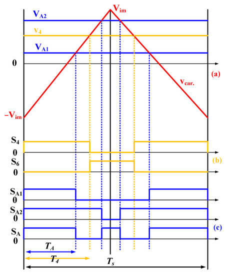
Figure 3.
(a) Modulation signals and carrier signals, (b) the duty cycle of the controlled rectifier, and (c) switching pulses for the upper switch for phase A inverter in sector 1 using the CBPWM.
The switching pattern and timing of the modulated switches may be described for the rectifier when the vector of the reference-input current is located in the first sector, as illustrated in Figure 3b. The formula in (9) defines the length of the gate pulse of the switch S4 (T4). The rectifier switch S4’s modulated signal ( is provided by (10). By comparing the modulated signal in (10) with the carrier signal as shown in Figure 3b, the working pulse of switch S4 is determined. Switch S1 is always on in the first sector, while switch S6’s operational pulse is the counterpart of switch S4’s pulse. Switches S2, S3, and S5 in the first sector are always off. The approach described in Table 1 may be used to compute the duty cycles and switching states for different sectors.
2.2. Five-Phase Inverter
Two modulation signals are utilized in controlling the inverter to achieve the necessary output voltage despite the volatility of the DC-link voltage. These signals are produced from duty ratios and , respectively. According to (11) and (12), these duty ratios are dependent on DC-link voltage. These represent the modulation signals for switch in a general formulation. M stands for output phase numbers A, B, C, D, and E in (11:14), while denote the output voltages’ maximum and minimum values, respectively. To construct the gate signal for the top switch of phase A, for example, in this case, two modulation signals, and , are needed. The waveforms of and are shown in Figure 3a, together with the carrier signal (). The two modulation signals and are then separately compared with the carrier signal to produce the two pulses and . The gate signal for switch ( in Figure 1), is finally determined using the logic-XNOR function, as shown in Figure 3c and (14). The block diagram in Figure 4 clearly shows this as well. Figure 3 makes it very clear that when the rectifier stage commutates, the inverter stage uses the zero vectors to ensure the rectifier’s zero DC-link current commutation. As a result, all currents flowing through the rectifier’s switches during commutation will be zero. A complex multistep commutation process is eliminated, and the switching loss of the rectifier stage is decreased. This will be proven through experimental measurements in the last part of this paper.
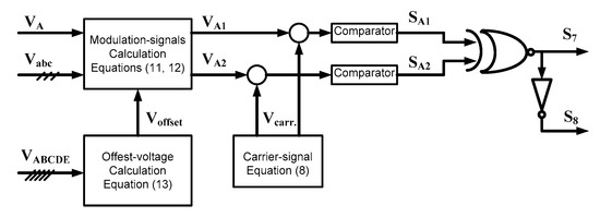
Figure 4.
The IMC’s inverter-CBPWM stage’s block diagram.
3. Five-Phase Synchronous Reluctance Motor
The considered SynRM in this paper is a rewound combined star–pentagon SynRM that was proposed in [3]. This motor consists of a 36-slot stator and 4-pole rotor. In this machine, the winding of each phase is divided into two coils per pole pair with an equal number of turns, 24 conductors/turns per coil. There are two coils for each pole pair, for a total of four coils, in the case of a 4-pole system, one for each phase. In Figure 5, each pair of nonadjacent series and parallel coils is represented by a single coil. All coils are connected in series and have the same number of turns. As indicated in Figure 5a,b, the phases might be joined to one another either in star or pentagon configurations.
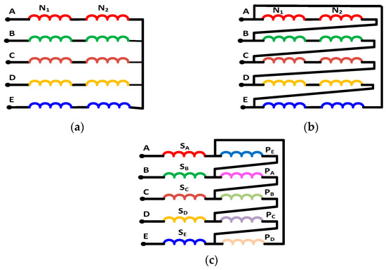
Figure 5.
(a) Star connection N1 = N2 = 24, (b) pentagon connection N1 = N2 = 29, and (c) combined star–pentagon connection N1 = 24, N2 = 29.
As illustrated in Figure 5c, one of the two winding groups is linked in a pentagon, while the other winding group is connected between the power electronic converter and the pentagon connection terminals to create a combined star–pentagon connection. According to (15) [2,3], the current of the pentagon winding () and the current of the star winding () are related to one another. The pentagon winding’s () number of turns must be greater than the star winding’s () number of turns in order for both windings to produce the same MMF [2,3]. The formula for the relationship between the number of turns is (16). However, because of the fabrication challenges, it can be challenging to achieve the ratio of 1.1756 between the turns of the two windings. This may not be a problem because different winding ratios that are close to 1.1756 can be selected [24]. The star and pentagon windings in Figure 5c have 24 and 29 conductors, respectively. Figure 6 shows the winding functions of the star and pentagon winding of phase B for SynRM 5. According to Figure 6, there will be an 18° phase difference between the two windings.
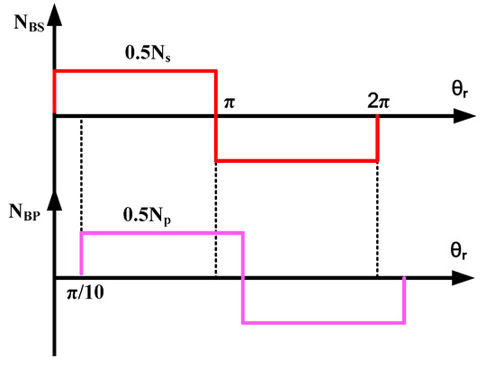
Figure 6.
The winding functions for the star and pentagon windings of phase B.
4. Analysis of Power Flow diagram
This section discusses and analyzes the power loss components of the proposed drive system. Figure 7 shows the power flow diagram of the proposed drive system. The power loss components of this drive system will be divided into two main components, e.g., converter losses and motor losses.
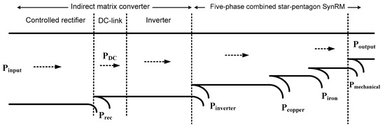
Figure 7.
The power flow diagram of the Five-phase SynRM drive system based on indirect MC.
4.1. Indirect Matrix Power Losses
Recently developed rapid switching devices and advancements in power semiconductor technology encourage the use of high switching modulation methods in power converters, which further reduces harmonic distortion. Regrettably, as the switching frequency is raised, the issue of power loss, such as switching loss, worsens. This indicates that switching loss considerably lowers system efficiency, which in turn prevents the switching frequency from being increased further. The power converter losses are rectifier losses (Prec) and inverter losses (Pinverter). Both rectifier and inverter have conduction losses and switching losses. It is recognized that the switching loss is the dominant component of the converter losses [25,26]. Hence, much effort has been exerted to minimize the converter switching losses and this is the main objective of the introduced CBPWM in the second section. Ensuring the rectifier switches modulation occurs at zero vector stator of the inverter guarantees zero switching losses for the rectifier. Hence, the converter losses are reduced. The different converter loss components will be investigated in the following subsections.
4.1.1. Rectifier Conduction Losses
The rectifier conduction losses () can be represented as in (17) [25,26]. In (17), , and are the internal resistance of the switch, the switch’s voltage drop, which is around 0.4 V, and the current flowing through the switch which equals the DC-link current in the MC, respectively. Note that represents the number of switches in the rectifier (12 switches).
4.1.2. Rectifier Switching Losses
The switching loss becomes a substantial portion of the converter’s overall power loss in high switching frequency applications when the switching frequency is raised. It has been found that the switching losses depend on the instantaneous current flowing in the rectifier switch and the rectifier modulation occurs at the zero vector stator of the inverter as introduced in the proposed CBPWM in the second section. Hence, the instantaneous current flowing through the rectifier’s switching is zero and hence the rectifier switching losses will be zero. In the end, the rectifier losses will be only the conduction losses, which are directly proportional to the current flowing in the switch.
4.1.3. Inverter Conduction Losses
The inverter conduction losses () can be given by (19) [25,26]. In (19), and are the number of switches in the inverter (10 switches) and the current flowing through the inverter switch which equals the positive half cycle of the motor phase current, respectively.
4.1.4. Inverter Switching Losses
According to switching time, instantaneous current and voltage values, and switching time itself, the switching losses of the rectifier may be roughly calculated as in (20). In (20), , and represent switching frequency, turn on and off time, respectively. Moreover, represent switching state, the total number of switchings, the instantaneous value of voltage, and the current for the switch, respectively.
4.2. The Motor Losses
The motor losses will be introduced in this section. These losses are divided into three parts: copper losses, iron losses, and mechanical losses.
4.2.1. The Copper Losses
The resistance of the copper wire put in the machines and the amount of current flowing through it determines the copper loss. The copper loss can be computed as in (21). In (21), , and represent the number of phases, the resistance per phase, and the motor phase current.
4.2.2. The Iron Losses
Based on Bertotti’s statistical loss theory [27], the iron losses of the SynRM are computed. The following is how the theory relies on loss separation into excess, hysteresis, and classical eddy current losses:
where f is the applied current’s frequency, Bm is its maximum flux density, and kh, kc, and ke are their respective hysteresis, classical eddy current, and excess losses coefficients, respectively. Additionally, , and d stand for material density in kg/m3, material conductivity, and lamination thickness, respectively. These coefficients were calculated by fitting loss curves with Ansys. The iron losses are fitted using the nonlinear least squares approach [28].
4.2.3. The Mechanical Losses
Bearing loss and aerodynamic loss are typically the two parts of the mechanical power loss produced by electrical machines. Both contact friction effects in the bearing assembly and the rotating/moving portions of the machine interacting with the fluid/air around them are responsible for the loss components.
5. Results and Discussion
A five-phase combined star–pentagon SynRM connected to indirect MC has been created in order to evaluate the effectiveness of the proposed CBPWM in providing zero rectifier switching losses (see Figure 8). Through a torque measuring sensor, the combined star–pentagon motor is connected to an induction motor and runs in torque control mode. The discussed multiphase drive system architecture is presented in Figure 1. The indirect MC controlled using a CBPWM is utilized to control the motor’s phase currents. The switching pulses for the converter are obtained through a DS 1103. Motor phase currents, phase voltages, DC-link current, and voltage, as well as input power to the drive system, are all monitored and recorded during measurements. Then, the computations of all the loss components that were described in the preceding section are done.
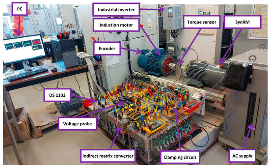
Figure 8.
The setup used for experimental validation.
As has been previously discussed, the conduction loss is the only and the dominant loss components in rectifier loss. This is thanks to zero switching losses in the rectifier that have been persevered by the applied CBPWM introduced previously in the second section. The objective of this section is to show or validate this claim. This will be done by comparing the rectifier losses, which are only conduction losses, at different operating voltages and currents. The conduction losses in the rectifier depend on the switch current which equals the DC-link current. Hence, this comparison will be done at different DC-link currents and at the same conditions, e.g., the same motor current, the same current angle, and the same operating speed. To obtain different DC-link currents at the same conditions, the input voltage will be varied. Figure 9a shows the DC-link current variation with the DC-link voltage at a current angle of 50° and different motor operating currents. There are six lines in Figure 9a, each line represents a fixed motor operating current. For fixed motor current (one line) in Figure 9a, it is noticed that the DC-link current decreases with the increase of the DC-link voltage. The DC-link voltage is adjusted by the supply voltage value. The same finding is also obtained at a different current angle of 25°, as shown in Figure 9b. Figure 10 shows the variation of the rectifier losses at different DC-link voltages. It is noticed in Figure 10 that the rectifier losses decrease with the increase in the DC-link voltage. This is because of the decrease of the DC-link current, which mainly affects the conduction losses that is the only loss components in the losses of the rectifier. Figure 11a,b show the variation of the total losses of the drive system at different DC-link voltage different motor phase currents, and current angles of 50° and 25°, respectively.
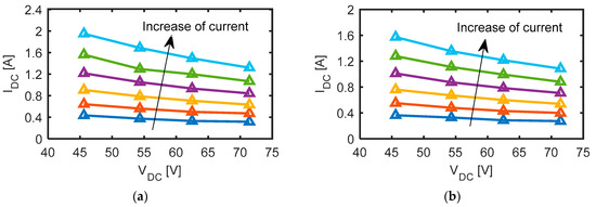
Figure 9.
The DC-link current at different DC-link voltages and different motor currents and current angles of (a) 50° and (b) 25°.
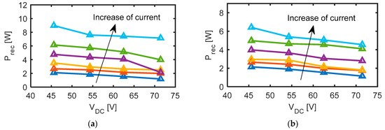
Figure 10.
The rectifier losses at different DC-link voltages and different motor currents and current angles of (a) 50° and (b) 25°.
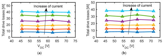
Figure 11.
The drive total losses at different DC-link voltages and different motor currents and current angles of (a) 50° and (b) 25°.
The instantaneous performance of the DC-link current at a motor current of 3 A, at a current angle of 25°, and at a line supply voltage of 40 V and 50 V is displayed in Figure 12a,b. It is discovered that when the supply line voltage increases, the DC-link current drops. Figure 13a,b show the instantaneous performance of the DC-link voltage at a motor current of 3 A, 25° current angle, and line supply voltages of 40 V and 50 V.
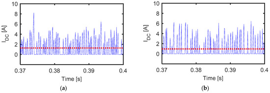
Figure 12.
The DC-link current at a motor current of 3 A, current angle of 25°, and supply line voltages of (a) 40 V and (b) 50 V. The red dotted line represents the mean value.
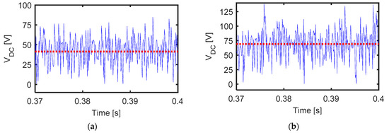
Figure 13.
The DC-link voltage at a motor current of 3 A, current angle of 25°, and supply line voltages of (a) 40 V and (b) 50 V. The red dotted line represents the mean value.
Figure 14 and Figure 15 show the output and the input characteristics of the IMC for the proposed drive system. The output line voltage, output phase voltage, and output phase current at 1500 rpm are shown in Figure 14a–c, respectively. The input phase voltage and current are shown in Figure 15a,b, respectively. Note that an LC input filter is connected between the IMC input terminals and the supply to minimize matrix switching as shown in Figure 15c [22]. The input filter parameters are the following: = 3 mH, Rf = 50 Ω, and = 10 μF.
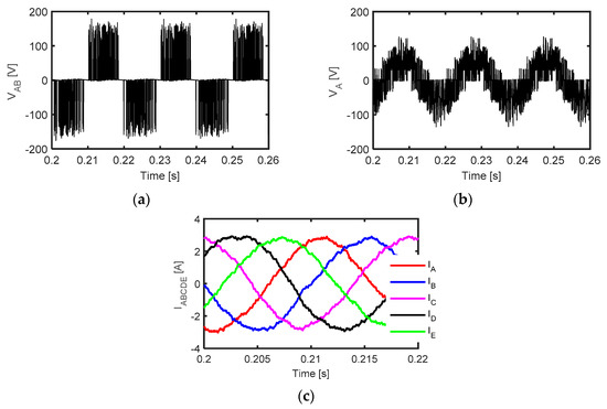
Figure 14.
Measured (a) line output voltage, (b) phase output voltage, and (c) phase output current at 1500 rpm.
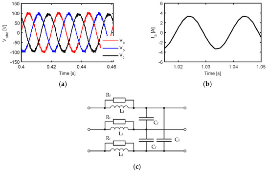
Figure 15.
Measured (a) input phase voltage, (b) input phase current (filtered), and (c) input filter connected between supply and IMC.
Figure 16 studies the performance of the proposed five-phase drive. Figure 16a compares the torque response of the proposed drive with the conventional three-phase drive. Both drives work at the same current, copper volume, and the same rated condition (3000 rpm and 17.3 A max). Figure 16b compares the measured and simulated results of the average torque of both drives at different current angles and rated conditions. From Figure 16a,b, the five-phase drive gives 13.35% higher torque compared to the three-phase drive. This is because of its higher magneto motive force (MMF) magnitude as shown in Figure 16c. Moreover, the torque ripple of the five-phase drive is about 30% lower compared to the three-phase drive. This is because of the lower MMF harmonics in the case of the five-phase drive, as shown in Figure 16d. Hence, the proposed drive shows improved performance. Figure 17a shows the performance of the drive system working in speed control mode and the reference speed is varied from 1500 rpm to 1000 rpm. It is noted that the required operating speed follows the set point of the reference speed. Figure 17b shows the performance of the drive system working in torque control mode and the operating current changes from half to one-fourth of the rated current.
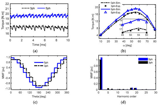
Figure 16.
The performance comparison of the proposed drive with the conventional three-phase drive at rated conditions. (a) Simulated torque versus time at the optimal current angle, (b) measured and simulated results for the average torque versus current angle, (c) MMF magnitude, and (d) MMF harmonic spectrum.
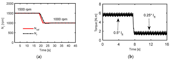
Figure 17.
The performance of the drive system working at (a) speed control mode and (b) torque control mode.
6. Conclusions
This study has examined a control method for a five-phase synchronous reluctance motor (SynRM) drive system based on a three-to-five-phase indirect matrix converter (IMC). Switching losses in this technology are maintained to a minimal value by ensuring that the rectifier stage encounters zero current commutation. To accomplish this, the rectifier and inverter stages are synchronized so that commutation in the rectifier stage occurs at zero inverter vectors, resulting in a zero DC-link current. As a consequence, the switching loss of the converter will be minimized, and the rectifier will have a null value of the switching losses. The various loss components of the power converter and motor have already been presented and studied. The suggested CBPWM has been experimentally validated to provide decreased switching losses in the IMC. In addition, the proposed drive system’s performance has compared to that of a typical three-phase SynRM-based inverter in the speed and torque control modes. The suggested drive offers 13.35% more torque than the three-phase drive. Furthermore, the torque ripple of the five-phase drive is approximately 30% less than that of the three-phase drive.
Author Contributions
Conceptualization, K.B.T.; methodology, K.B.T.; software, K.B.T.; validation, K.B.T.; investigation, K.B.T.; writing—original draft preparation, K.B.T.; writing—review and editing, M.N.I. and P.S.; visualization, M.N.I. and P.S.; supervision, M.N.I. and P.S. All authors have read and agreed to the published version of the manuscript.
Funding
The authors acknowledge the Special Research Fund of Ghent University, Belgium (BOF).
Institutional Review Board Statement
Not applicable.
Informed Consent Statement
Not applicable.
Data Availability Statement
Not applicable.
Conflicts of Interest
The authors declare no conflict of interest.
References
- Yepes, A.G.; Doval-Gandoy, J.; Baneira, F.; Pérez-Estévez, D.; López, O. Current Harmonic Compensation for $n$-Phase Machines with Asymmetrical Winding Arrangement and Different Neutral Configurations. IEEE Trans. Ind. Appl. 2017, 53, 5426–5439. [Google Scholar] [CrossRef]
- Abdel-Khalik, A.; Elgenedy, M.; Ahmed, S.; Massoud, A. An improved fault-tolerant five-phase induction machine using a combined star/pentagon single layer stator winding connection. IEEE Ind. Electron. 2016, 63, 618–628. [Google Scholar] [CrossRef]
- Tawfiq, K.B.; Ibrahim, M.N.; EL-Kholy, E.E.; Sergeant, P. Construction of Synchronous Reluctance Machines with Combined Star-Pentagon Configuration Using Standard Three-Phase Stator Frames. IEEE Trans. Ind. Electron. 2022, 69, 7582–7595. [Google Scholar] [CrossRef]
- Agamloh, E.B.; Boglietti, A.; Cavagnino, A. The Incremental Design Efficiency Improvement of Commercially Manufactured Induction Motors. IEEE Trans. Ind. Appl. 2013, 49, 2496–2504. [Google Scholar] [CrossRef]
- Yamazaki, K. Torque and efficiency calculation of an interior permanent magnet motor considering harmonic iron losses of both the stator and rotor. IEEE Trans. Magn. 2003, 39, 1460–1463. [Google Scholar] [CrossRef]
- Mademlis, C.; Kioskeridis, I.; Margaris, N. Optimal efficiency control strategy for interior permanent-magnet synchronous motor drives. IEEE Trans. Energy Convers. 2004, 19, 715–723. [Google Scholar] [CrossRef]
- Fang, L.; Jung, J.; Hong, J.; Lee, J. Study on High-Efficiency Performance in Interior Permanent-Magnet Synchronous Motor with Double-Layer PM Design. IEEE Trans. Magn. 2008, 44, 4393–4396. [Google Scholar] [CrossRef]
- Guglielmi, P.; Boazzo, B.; Armando, E.; Pellegrino, G.; Vagati, A. Permanent-Magnet Minimization in PM-Assisted Synchronous Reluctance Motors for Wide Speed Range. IEEE Trans. Ind. Appl. 2013, 49, 31–41. [Google Scholar] [CrossRef]
- Bonthu, S.S.R.; Baek, J.; Choi, S. Comparison of optimized permanent magnet assisted synchronous reluctance motors with three-phase and five-phase systems. In Proceedings of the 2014 IEEE Energy Conversion Congress and Exposition (ECCE), Pittsburgh, PA, USA, 14–18 September 2014; pp. 2396–2402. [Google Scholar]
- Tawfiq, K.B.; Ibrahim, M.N.; EL-Kholy, E.E.; Sergeant, P. Comparative Analysis of Refurbishing Methods of Three-Phase Synchronous Reluctance Machines to Five-Phase with Minimum Cost. IEEE Trans. Ind. Appl. 2021, 57, 6007–6022. [Google Scholar] [CrossRef]
- Tawfiq, K.B.; Ibrahim, M.N.; EL-Kholy, E.E.; Sergeant, P. Performance Improvement of Synchronous Reluctance Machines—A Review Research. IEEE Trans. Magn. 2021, 57, 10. [Google Scholar] [CrossRef]
- Tawfiq, K.B.; Ibrahim, M.N.; EL-Kholy, E.E.; Sergeant, P. Performance Analysis of a Rewound Multiphase Synchronous Reluctance Machine. IEEE J. Emerg. Sel. Top. Power Electron. 2022, 10, 297–309. [Google Scholar] [CrossRef]
- Hu, J.S.; Chen, K.Y.; Shen, T.Y.; Tang, C.H. Analytical solutions of multilevel space vector PWM for Multi-phase voltage source inverters. IEEE Trans. Power Electron. 2011, 26, 1489–1502. [Google Scholar] [CrossRef]
- Levi, E.; Bojoi, R.; Profumo, F.H.; Toliyat, A.; Williamson, S. Multiphase induction motor drives—A technology status review. IET Electr. Power Appl. 2007, 1, 489–516. [Google Scholar] [CrossRef]
- Toliyat, H.A.; Xu, L.; Lipo, T.A. A Five Phase Reluctance Motor with High Specific Torque. IEEE Trans. Ind. Appl. 1992, 28, 659–667. [Google Scholar] [CrossRef]
- Tawfiq, K.B.; Ibrahim, M.N.; EL-Kholy, E.E.; Sergeant, P. An Improved Fault-Tolerant Control of a Five-Phase Synchronous Reluctance Motor Connected to Matrix Converter. In Proceedings of the 2021 IEEE 13th International Symposium on Diagnostics for Electrical Machines, Power Electronics and Drives (SDEMPED), Virtual, 22–25 August 2021; pp. 276–281. [Google Scholar]
- Tawfiq, K.B.; Ibrahim, M.N.; Sergeant, P. An Enhanced Fault-Tolerant Control of a Five-Phase Synchronous Reluctance Motor Fed from a Three-to-Five-phase Matrix Converter. IEEE J. Emerg. Sel. Top. Power Electron. 2022, 10, 4182–4194. [Google Scholar] [CrossRef]
- Tran, Q.; Lee, H. An Advanced Modulation Strategy for Three-to-Five-Phase Indirect Matrix Converters to Reduce Common-Mode Voltage with Enhanced Output Performance. IEEE Trans. Ind. Electron. 2018, 65, 5282–5291. [Google Scholar] [CrossRef]
- Nguyen, T.D.; Lee, H. A New SVM Method for an Indirect Matrix Converter with Common-Mode Voltage Reduction. IEEE Trans. Ind. Inform. 2014, 10, 61–72. [Google Scholar] [CrossRef]
- Tran, Q.H.; Nguyen, T.D.; Phuong, L.M. Simplified Space-Vector Modulation Strategy for Indirect Matrix Converter with Common-Mode Voltage and Harmonic Distortion Reduction. IEEE Access 2020, 8, 218489–218498. [Google Scholar] [CrossRef]
- Jayaprakasan, S.; Ashok, S.; Ramchand, R. Analysis of Current Error Space Phasor for a Space Vector Modulated Indirect Matrix Converter. IEEE Trans. Ind. Electron. 2021, 69, 4451–4459. [Google Scholar] [CrossRef]
- Tawfiq, K.B.; Ibrahim, M.N.; Sergeant, P. A Simple Commutation Method and a Cost-Effective Clamping Circuit for Three-to-Five-Phase Indirect-Matrix Converters. Electronics 2022, 11, 808. [Google Scholar] [CrossRef]
- Nielsen, P.; Blaabjerg, F.; Pederson, J.K. Novel Solutions for Protection of Matrix Converter to Three Phase Induction Machine. In Proceedings of the IEEE IAS Conference Record, New Orleans, LA, USA, 5–9 October 1997; pp. 1447–1454. [Google Scholar]
- Lei, Y.; Zhao, Z.; Wang, S.; Dorrell, D.G.; Xu, W. Design and Analysis of Star–Delta Hybrid Windings for High-Voltage Induction Motors. IEEE Trans. Ind. Electron. 2011, 58, 3758–3767. [Google Scholar] [CrossRef]
- Kaku, B.; Miyashita, I.; Sone, S. Switching Loss Minimised Space Vector PWM Method for IGBT Three-Level Inverter. IEE Proc. Electr. Power Appl. 1997, 144, 182–190. [Google Scholar] [CrossRef]
- Arafat, A.; Choi, S. Comparison of electrical losses in an inverter-fed five-phase and three-phase permanent magnet assisted synchronous reluctance motor. In Proceedings of the 2016 IEEE Applied Power Electronics Conference and Exposition (APEC), Long Beach, CA, USA, 20–24 March 2016; pp. 2847–2854. [Google Scholar]
- Bertotti, G. General properties of power losses in soft ferromagnetic materials. IEEE Trans. Magn. 1998, 24, 621–630. [Google Scholar] [CrossRef]
- Ibrahim, M.N.; Sergeant, P.; Rashad, E.M. Synchronous Reluctance Motor Performance Based on Different Electrical Steel Grades. IEEE Trans. Magn. 2015, 51, 11. [Google Scholar] [CrossRef] [Green Version]
Publisher’s Note: MDPI stays neutral with regard to jurisdictional claims in published maps and institutional affiliations. |
© 2022 by the authors. Licensee MDPI, Basel, Switzerland. This article is an open access article distributed under the terms and conditions of the Creative Commons Attribution (CC BY) license (https://creativecommons.org/licenses/by/4.0/).