Abstract
An electromechanical coupling driving system is a commonly used system for large overloading ships. In this paper, a dual input electromechanical coupling model, including an inverter power supply, three-phase induction motor, fixed-axis gear, and load, is established. The influences of the gear error, inverter, and coupling stiffness on the vibration characteristics of the system are studied, and the influences of each parameter on the vibration characteristics are analyzed. The inverter power supply part considers the constant voltage–frequency ratio control and sinusoidal pulse width modulation, as well as the inverter. The motor part uses the dynamic motor model based on the equivalent circuit. The fixed-axis gear section uses a translation–torsion model with time-varying mesh stiffness and damping. The mechanical part and the motor part are coupled with the load torque of the motor. The results show that the greater the error of the gear, the greater the vibration of the system, and the rotation frequency error is the main factor. Secondly, by comparing the influence of error value and accuracy difference on vibration, we found that when an accuracy difference exists, the dominant factor of system vibration is the accuracy difference. Thirdly, the use of an inverter also increases the vibration of the electromechanical coupling system. Finally, we found that the lower stiffness of the elastic coupling reduced the vibration of the system.
1. Introduction
The ship’s power system is mainly composed of the main engine, a transmission device, and a propeller. The ship’s engine and the propeller mainly rely on the transmission device to transmit energy, thereby, generating thrust and making the ship travel. In terms of the form of main engines, there are generally steam engines, gas turbines, diesel engines, nuclear power engines, etc. These main engines have convenient fuel storage and high reliability in maritime navigation and can support ships in transoceanic voyages.
In recent years, with the improvement of environmental protection requirements, hybrid ships, new energy ships, and especially electric ships have developed rapidly. Electric ships have the advantages of large payload, low vibration, good flexibility, maneuverability, and a high degree of equipment automation; however, the main engine of electric ships has higher power requirements. As early as the year 2000, the total power of some large ships exceeded 8000 kw.
After more than 20 years of development, the power of military warships reached 12,000 kw [1], and some large ocean-going cargo ships even exceeded 20,000 kw. This puts forward higher requirements for the power system, such as the use of higher-power inverters, higher-efficiency motors, better-performance rectifiers [2], etc. In addition to the main engine, the transmission device is also one of the important systems of the ship. At present, the large transport ships still in service at home and abroad mainly use hydraulic transmission and gear transmission.
The hydraulic transmission transmits power through the rotation of the pump gear and the turbine [3], which is stable but the efficiency is not high, while the gear transmission relies on the characteristics of high transmission efficiency, excellent transmission reliability, long service life, and simple and compact structure, becoming one of the most widely used power transmission devices. With the increase of the power of the ship’s main engine, the increase of the transmission speed, and the increase in the transmission load, the vibration problem of the ship’s electromechanical coupling system has become increasingly apparent [4]. These vibrations will affect the working performance of the ship and its stability, and even affect the health of the occupants in severe cases. Therefore, it is necessary to study the vibrations of electromechanical coupling systems.
At present, many scholars have studied the vibration problem in electromechanical coupling systems. Han et al. [5] analyzed the influence degree of parameters, such as the coupling stiffness, shaft stiffness, coupling damping, and shaft damping, on the shaft torsional vibration with the numerical analysis method. Xiao et al. [6] established a mathematical model and vibration equation of a shaft system using the lumped parameter method. The operation process of asymmetric twin-engine propulsion shafting and the effects of phase angle and motor excitation on the shafting torsional vibration were mainly studied.
Zhang et al. [7] studied the variation of the dynamic characteristics of mechanical transmission systems with the stiffness, damping coefficient, and electromagnetic torque by using the equivalent nonlinear dynamic model of a mechanical transmission system. Yi et al. [8] established an induction motor model based on an equivalent circuit and a dynamic model of multi-stage gear transmission and analyzed the influence of the electromagnetic characteristics of the motor on the inherent characteristics and dynamic response of the transmission system.
Shu et al. [9] proposed an electromechanical coupling dynamic model that can reflect the MDS under time-varying load and speed conditions. On this basis, the dynamic characteristics and synchronization characteristics of MDS under three typical working conditions are studied. Xiao et al. [10] established a motor-electromechanical coupled vibration model to analyze the torsional vibration characteristics of the motor during startup. Jiang et al. [11] studied the electromechanical coupling torsional resonance characteristics of low-speed and high-power permanent magnet synchronous motor-driven multi-stage gear transmission system, considering the electromagnetic effect and bending-torsional vibration characteristics of permanent magnet synchronous motor, and established a suitable electromechanical coupling dynamics model of the speed regulation process.
Bai et al. [12] analyzed the dynamic characteristics of the electromechanical model combining the nonlinear magnetic permeability network model of a squirrel-cage asynchronous motor and the lateral–torsional coupled dynamic model of a planetary gear rotor system. Zhang et al. [13] established a synchronous motor and mechanical drive system and found through simulation that when the harmonic torque frequency is equal to or close to the natural frequency of torsional vibration of the mechanical drive system, electromechanical coupling vibration of mechanical drive system will be induced. Chen et al. [14] established a lateral-torsional dynamics model of the electromechanical coupling under electromagnetic excitation based on the Lagrange–Maxwell method and studied the effects of electromagnetic and mechanical parameters on mechanical vibration stability.
Szolc et al. [15] studied the influence of electromagnetic flux between stator and rotor on dynamic characteristics of the mechanical system by constructing a circuit model of asynchronous motor and structural hybrid drive system model. Lysenko et al. [16] considered constant voltage–frequency ratio control and simulated a three-phase inverter power supply and induction motor. The existing literature has conducted relevant research work on motor gear systems; however, it mainly focuses on the analysis of motors or gear trains, respectively. The researches on the electromechanical coupling are less, and the systems are mainly single electric input systems.
Due to the power confluence, the dual electric input system has strong mechanical coupling and electromechanical coupling characteristics, which will result in complex dynamic characteristics. Therefore, an electromechanical coupling model of the dual electric input systems by considering gear errors, frequency converter harmonic components, motors, and elastic couplers was established. The influences of parameters, such as the gear errors, stiffness of couplers, frequency converter harmonics, etc., on the vibration of the dual electric input system were also investigated.
2. Modeling
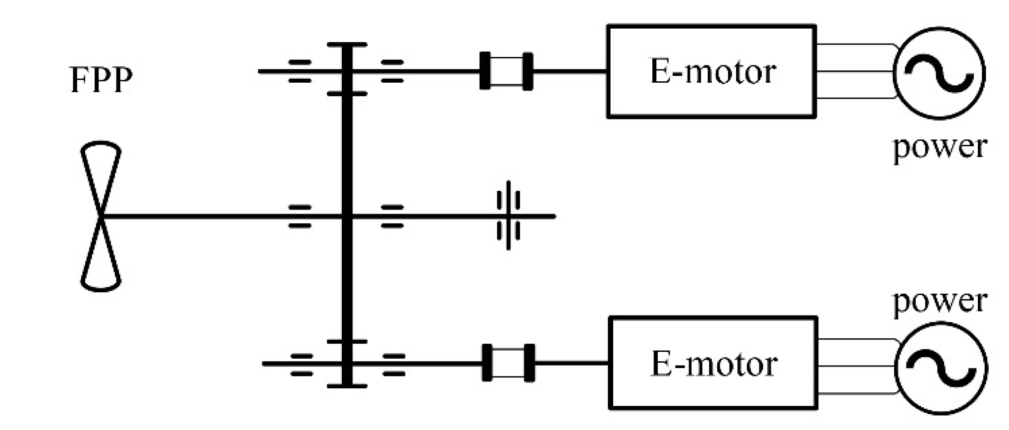
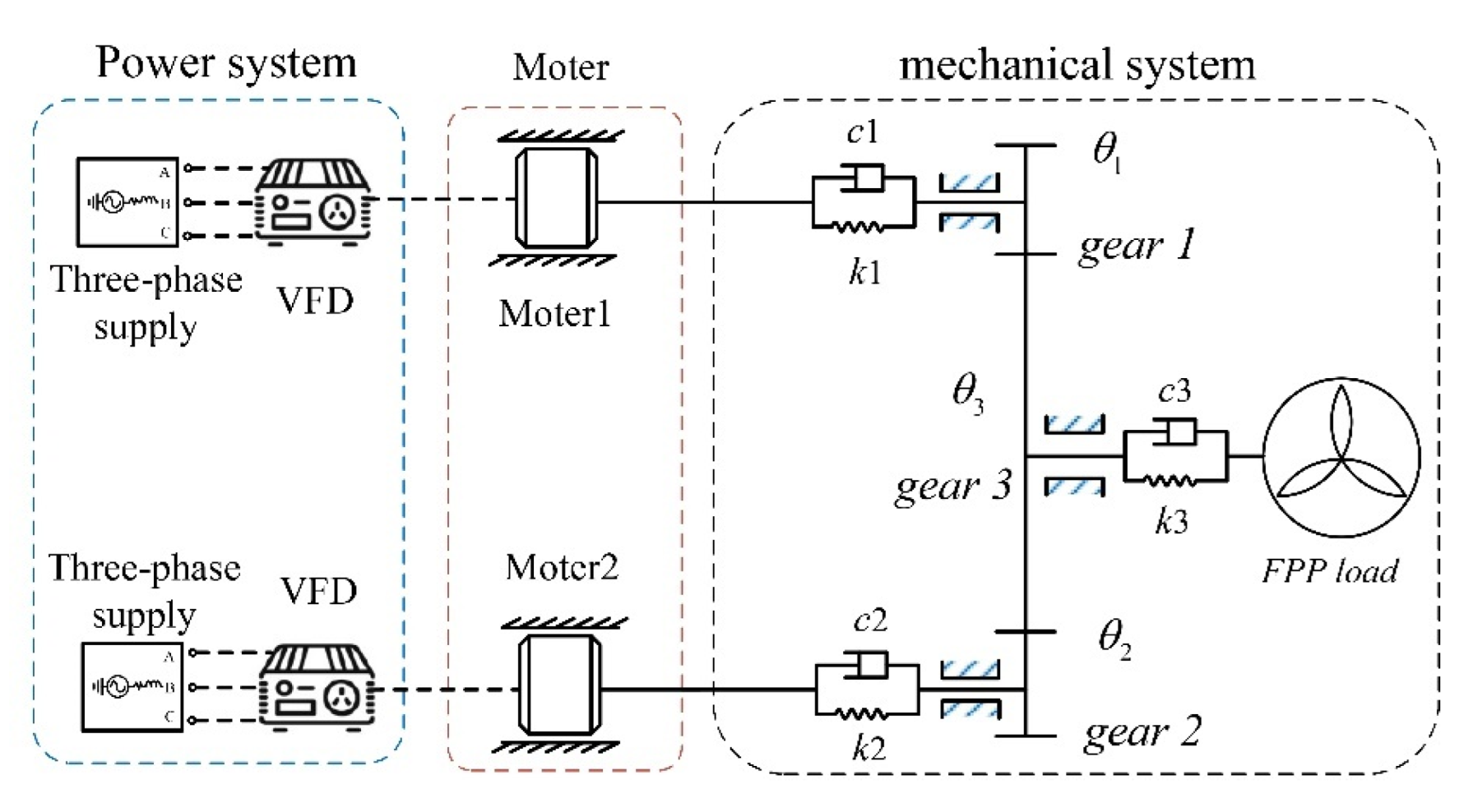
The power transmission system of electric ships with two engines and one propulsion shaft is shown in Figure 1. Its electromechanical coupling dynamic modeling is shown in Figure 2. The model includes the working power supply, the motor, the elastic coupling, the fixed shaft gear train, and the fixed pitch propeller (FPP) load.
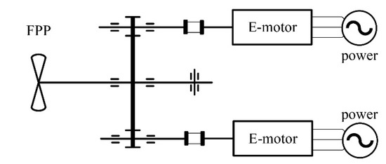
Figure 1.
Schematic diagram of two engines and one shaft propulsion system.
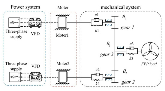
Figure 2.
Model of the ship’s two-engine and one-shaft propulsion system.
2.1. The Translation–Torsion Model of the Fixed-Axle Gear Train
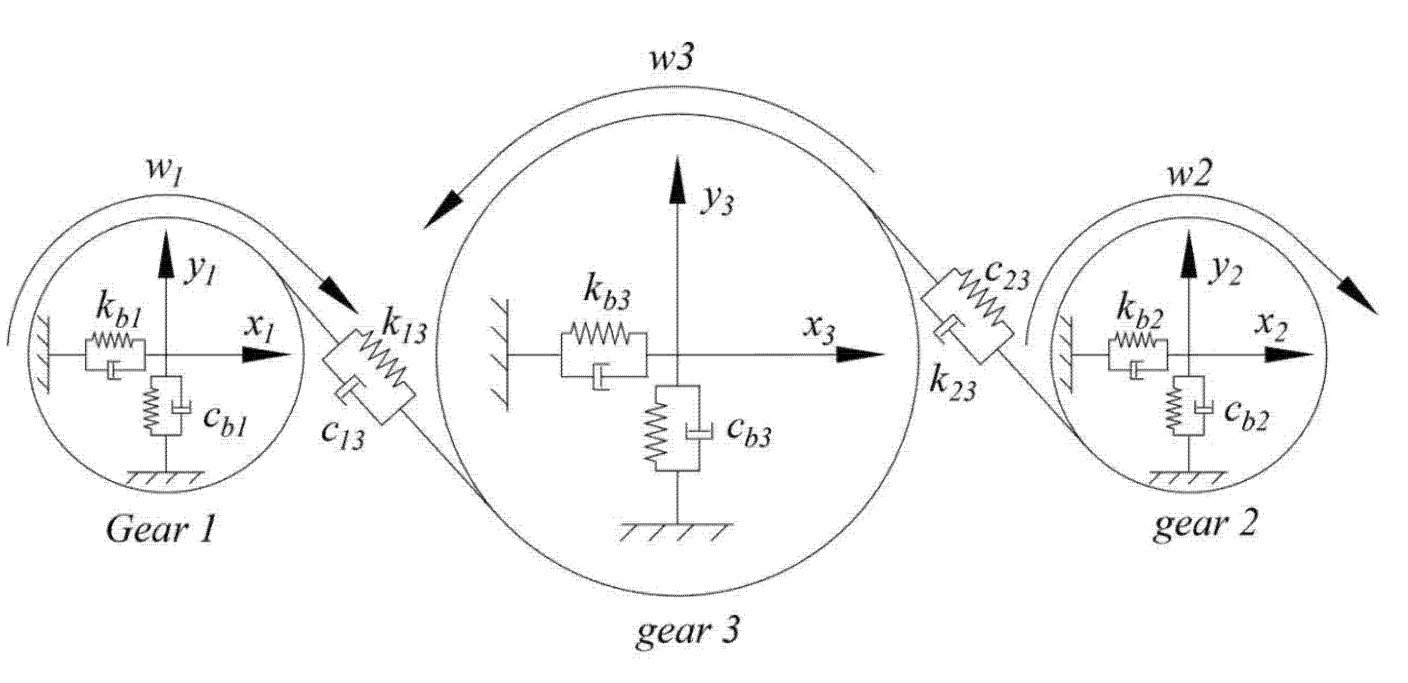
In this section, the translation–torsion dynamics model of the fixed-axis gear system is established as shown in Figure 3. Gear 1 and gear 2 are the two input gears of the system, and gear 3 is the output gear. The static coordinate system oixiyi (i = 1, 2, 3) is constructed, and the dynamic equation of the gear train can be deduced using Newton’s law.
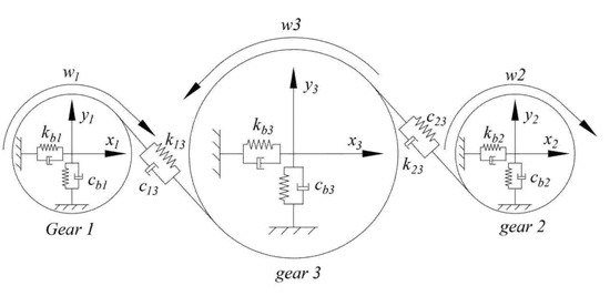
Figure 3.
Dynamic model of the fixed axle gear train.
The governing equations of each gear of the fixed-axis gear train are established as shown in the following Equations (1)–(3):
The meshing deformation of the fixed-axis gear along the meshing line is expressed as follows:
where represent the moment of inertia and mass of each gear, represents the pressure Angle of the gear and represent the horizontal and vertical displacements of the gear, respectively; indicates the support stiffness and support damping of the bearing to each component, represents the torsional stiffness and damping of each axis, represents the Angle of the gear, represents the rotation Angle of the rotor of the motor, represents the Angle of the Angle of the propeller load, and represents the nodal circle radius of each gear. are the input torques of gear 1 and gear 2, respectively, which can be expressed as , .
The fixed-axis gear meshing force and time-varying meshing stiffness [8] are as follows:
where is the average mesh stiffness over one mesh cycle, calculated by the formula used in ISO 6336-1-2006; al is the Fourier expansion coefficient; l is the harmonic order; is the phase angle of mesh stiffness. In Equation (4), is the comprehensive meshing error between the gears, including the rotational frequency error and mesh frequency error. is the Fourier expansion coefficient of the mesh frequency error. is the amplitude of the rotation frequency error, which can be obtained according to the accuracy level according to ISO1328-1:2013. are the phase angles, which are expressed as follows:
2.2. Motor-Equivalent Circuit Model
To obtain the electromechanically coupled vibration characteristics of the system, the electromagnetic dynamic model of the motor is performed. This model uses a set of three homogeneous linear differential equations, including voltage equation, flux linkage equation, and electromagnetic torque to describe the electro-magnetic dynamics of the motor [17]. The equivalent circuit model is established in the two-phase rotating d−q coordinate system to describe the motor by using Park transformation. The equivalent circuit [18] is shown in Figure 4.
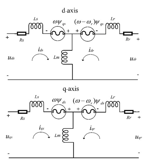
Figure 4.
Motor equivalent circuit in d−q coordinate system.
The voltage equation is:
In the formula, the subscripts d and q represent the components on the d–q coordinate. The subscripts s, r represent the stator-related quantities and rotor-related quantities, respectively. u, i, r, represent the voltage, current and resistance, respectively. ω indicates the mechanical and electromagnetic angular velocities of the rotor. ψ is the flux linkage, and the flux linkage equation of the stator is:
where Ls and Lr are the electronic and stator winding leakage inductances. Lm is the electromagnetic mutual inductance, and the formula of the electromagnetic torque of the motor is:
2.3. Elastic Coupling and Load Model
The elastic coupler used in the system is a heavy-duty high-elastic coupler. The elastic characteristics of the coupler may heavily affect the torsional vibration of the system. The classical stiffness–damping model is adopted for the elastic coupler, which can ensure the accuracy of the model while simplifying the calculation as much as possible. To simplify the calculation, the motor–gear shaft and the coupling are simplified as one [19]. The stiffness of the coupler and the shaft is replaced by the synthetic stiffness , and the damping of the coupler and the shaft is replaced by the synthetic damping .
The load of the system is from the fixed-pitch propeller (FPP). The torque model of the propeller is modeled as [20]:
where Km is the dimensionless coefficient of the propeller drag torque; p is the density of seawater; n is the velocity of the propeller, and Dp is the propeller diameter.
2.4. Inverter Power Supply Model
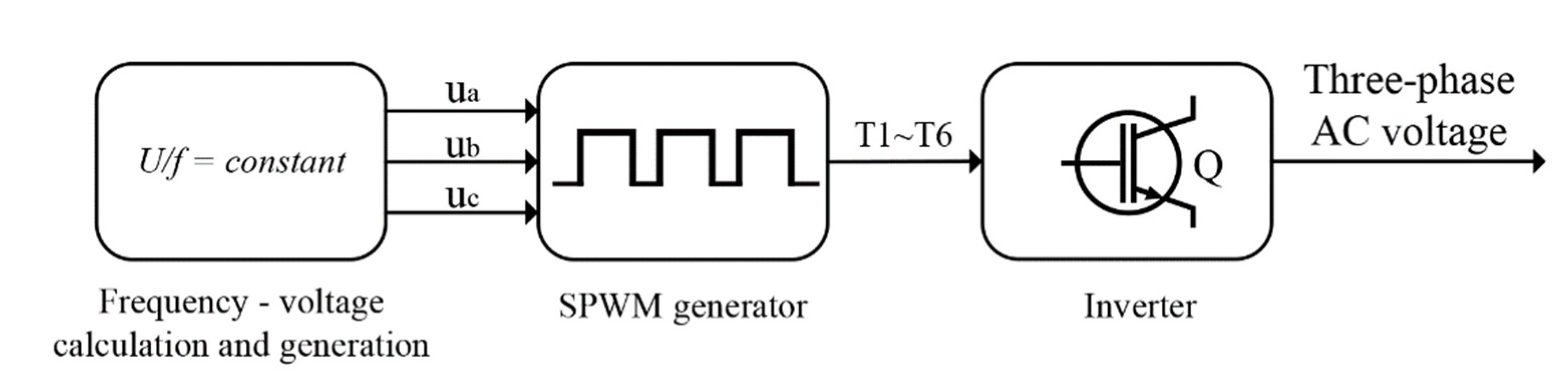
In this model, the inverter power supply model adopts constant voltage–frequency ratio control to calculate the voltage and current and drives the inverter power supply through the signal generated by sinusoidal pulse width modulation (SPWM). This method can start the motor or adjust the speed of the motor [21]. Figure 5 shows the schematic diagram of the inverter power drive.
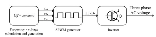
Figure 5.
Inverter driving schematic.
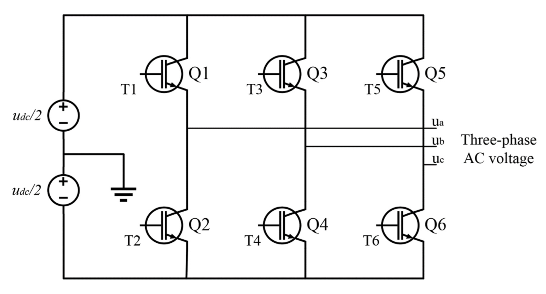
The inverter is composed of six power switching device IGBTs [22], as shown in Figure 6, the input DC voltage, through the constant voltage–frequency ratio control and SPWM pulse width modulation output pulse wave to control the power switching device IGBT on and off to adjust the voltage and current of the output three-phase AC, and then realize the drive control of the load.

Figure 6.
Inverter model.
3. Results
In this study, the dynamic model of the electromechanical coupled system, including the inverter power supply, the three-phase asynchronous motor, the fixed-shaft gear system, and the fixed-pitch propeller load is established. First, the dynamic characteristics of the system under working conditions are investigated, and then the effects of input gear errors, working power supply, and coupling stiffness on the system are studied.
In MATLAB/Simulink, a fixed-axis gear system model, including time-varying mesh stiffness and damping, is established by using an S-function, and an inverter power supply model, including constant voltage–frequency ratio control, SPWM generator, inverter, and a three-phase asynchronous machine, is built. The motors and gear system are connected by the electromagnetic torque and the torque on the motor shaft. The equation is as follows:
where n = 1, 2 indicates the motor number; Ten represents the electromagnetic torque of the nth motor; Tn is the load torque of the motor n, which is given in Section 2.2; Fµ indicates the viscous friction coefficient; and θMn is the rotation angle of motor n. The designed parameters of the gear train are listed in Table 1, where the stiffnesses are chosen according to the reference [8]. The motor parameters are listed in Table 2, which is calculated according to the references [17,21] based on the used motor. The power supply parameters are shown in Table 3, which are the motor power parameters.

Table 1.
Parameters of the gear train.
Table 2.
Parameters of the motors.
Table 3.
Power supply data.
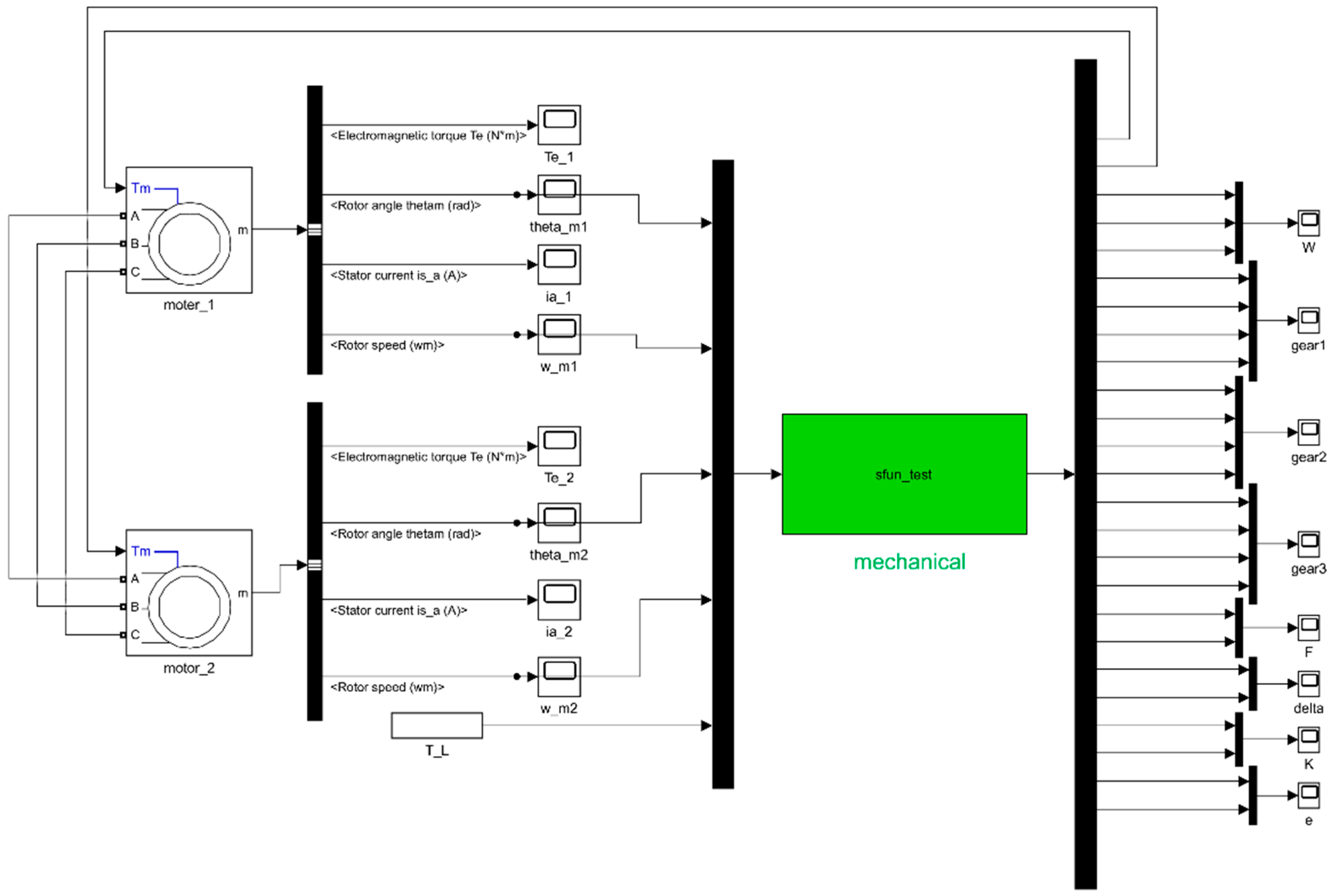
The MATLAB/Simulink modeling block diagrams are shown in Figure 7 and Figure 8. Figure 7 is the Simulink block diagram of inverter power supply, and Figure 8 is the Simulink block diagram of electromechanical system. The two parts are connected through three-phase AC power supply. The sfun_test function is the modeling of fixed-shaft gear shafting.
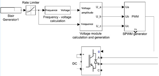
Figure 7.
Simulink block diagram of inverter power supply.

Figure 8.
Simulink block diagram of electromechanical system.
3.1. Dynamic Characteristics of the System under Working Conditions
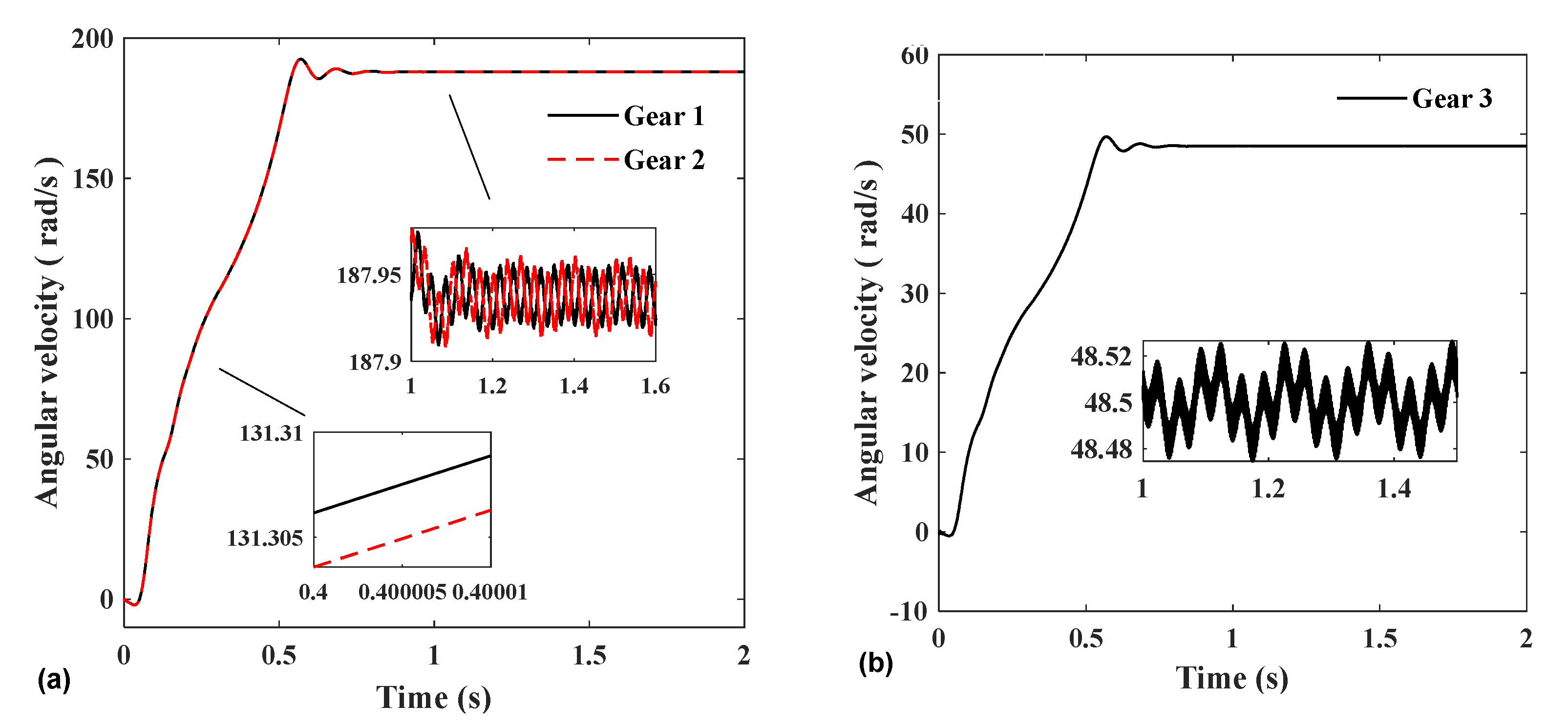
In this section, the vibration of each physical quantity of the system in the start-up and steady-state stages of the model under actual operating conditions is mainly introduced. Figure 9 shows the rotational speed of the three gears at start-up and steady-state. The rotational speed of the two input gears and the output gear both have vibrations with an amplitude of about 0.02 rad/s when they reach a steady state. This is because the model considers the combined effects of time-varying mesh stiffness, error, and inverter power supply.

Figure 9.
(a) Angular velocities of gears 1 and 2. (b) Angular velocities of gear 3.
In Figure 10, the two groups of meshing forces have the same amplitude in the time domain; however, there is a phase difference, which is caused by the phase difference between the two groups of gears during meshing. In the frequency domain, the frequency spectrum of the two meshing forces is roughly the same. The frequency spectrum mainly includes the meshing frequency fm of gear pairs 1–3 and 2–3, the double frequency 2fm, the triple frequency 3fm, etc., and also includes the frequency generated by the inverter. The modulation frequency of the triangular carrier frequency domain fc and the power fundamental frequency f1: fc-2f1 adn fc + 2f1.
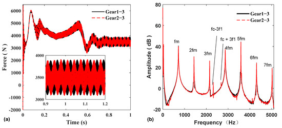
Figure 10.
Gear 1–3, Gear 2–3 mesh force: (a) time domain; (b) frequency domain.
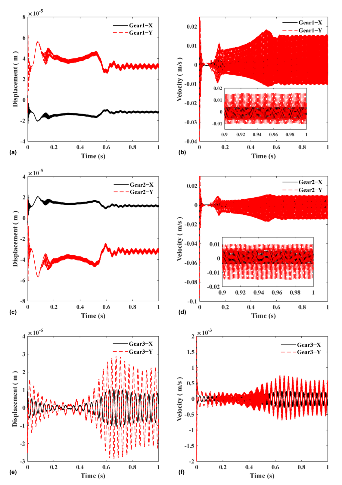
Figure 11 shows the displacement and speed changes of the three gears in the time domain. From the figure, the horizontal and vertical displacement directions of input gear 1 and input gear 2 are opposite, and the magnitudes are equal. There is vibration in both gears after entering a steady-state, which is the same trend as the meshing force. This shows that the displacement of the gear is the result of the meshing force, which is consistent with the result that the main component in the frequency spectrum is meshing frequency. In addition, the vertical displacement of the two gears is larger than the horizontal direction, which is caused by the magnitude of the components of the meshing force in these two directions.
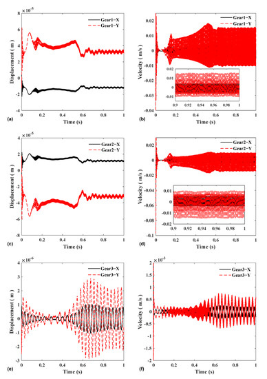
Figure 11.
Horizontal and vertical displacement and vibration velocity of three gear: (a) gear 1 displacement; (b) gear 1 vibration velocity; (c) gear 2 displacement; (d) gear 2 vibration velocity; (e) gear 3 displacement; and (f) gear 3 vibration velocity.
This is consistent with the pressure angle set by the model. Comparing the input gear 3 and the output gear 1.2, it can be seen that the displacement of the output gear is an order of magnitude smaller than that of the input gear, and the amplitude is also smaller than that of the input gear. This is because, in this model, the vibration source of the intermediate gear is the vector sum of the forces of the two input gears, and the two forces cancel a part, thereby, reducing the vibration of the intermediate gear. This shows that the dual-input fixed-axle gear train can reduce the displacement and vibration of the common gear to a certain extent.
3.2. Influences of Errors on Vibration
In this section, the influence of the gear tooth profile error on vibration is mainly studied. This paper studies the daul input system, and the system itself is relatively sensitive to error. In addition, the gear manufacturing error is random, which implies that the system of two input gear must have accuracy difference. To enhance the comparison effect, three different sets of parameters are used for simulation, namely case 1, case 2 and case 3. In case 1, the errors of the three gears were set to be close to the maximum allowable values with a accuracy of six degrees, and the errors of the two input wheels were roughly the same. In case 2, the error of gear 3 remained unchanged, and the error of gear 1,2 was set to 0 as the ideal gear. In case 3, the error of gear 1,3 remained the same as case 1, and the error of gear 2 was set to 0. The data settings of each group are shown in Table 4.
Table 4.
Error values for analyzed three cases.
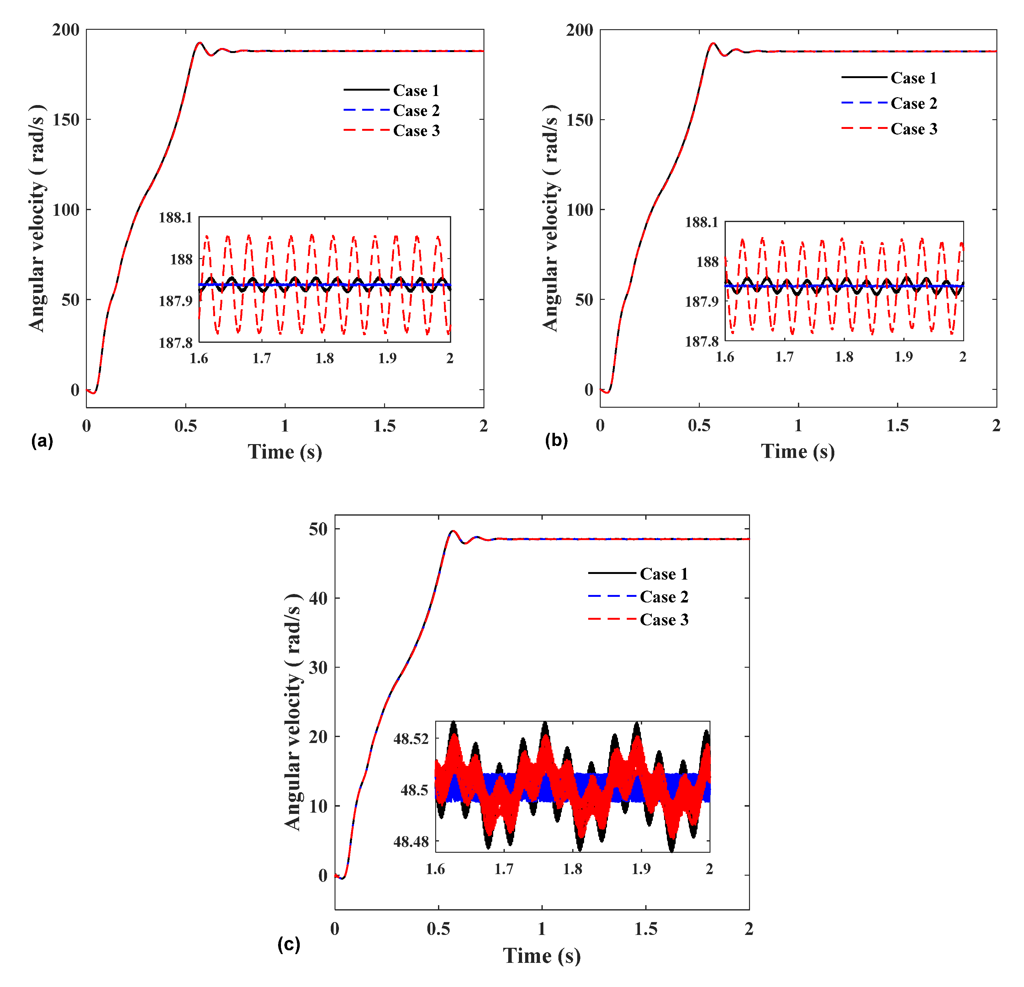
After entering the steady-state, it can be seen from Figure 12a,b that the vibration of control group 1 is the smallest, and the vibration of control group 2 is the largest. By comparing the Case 1 with the Case 2, it can be found that when the errors of gears 1 and 2 are set to 0, the angular velocity hardly vibrates. In Case 1, the influence of random error on the vibration amplitude of angular velocity was less than 0.05 rad/s. The simulation results of Case 3 showed that the vibration was much greater than that of the first two groups.
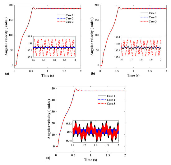
Figure 12.
Comparison of experimental group, control group 1, and control group 2: (a) Gear 1; (b) Gear 2; and (c) Gear 3.
According to Equation (6) in Section 2.1, the error model adopted in this paper is mainly composed of the mesh frequency error and the rotation frequency error, and it can be seen from the query of ISO1328-1:2013 standard that the value of the rotation frequency error is much larger than the mesh frequency error. Through the error calculation method, it can be known that the main influence on the system vibration is the rotation frequency error. The range of error mainly depends on these two values, and the greater the frequency error, the more severe the vibration.
In addition, the variation range of the time-varying error in the experimental group is much larger than that of the Case 3 (this is because the error of the gear 2 is set to 0, which can be obtained by calculation); however, its vibration is much smaller than that of the Case 3, under the control variable, this result shows that the vibration of the system is not only affected by the amplitude of the rotational frequency error but also related to the precision difference between the two input wheels. The greater the precision difference, the greater the vibration. However, Figure 12c shows that the speed vibration of gear 3 has little effect on the accuracy difference between the two input gears. When the comprehensive error is larger, the speed vibration of gear 3 is larger.
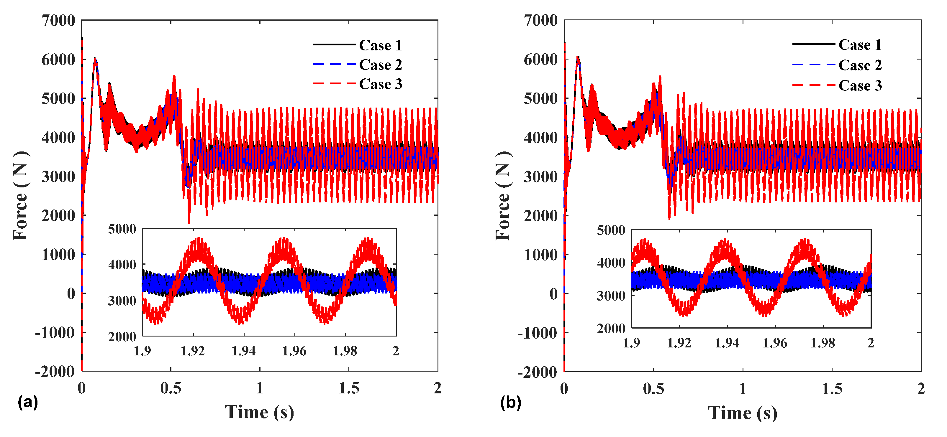
Figure 13 shows the meshing force and the displacement and vibration of each gear in the horizontal and vertical directions under three sets of parameters. Figure 13a,b show the change in the meshing force of the two pairs of gears, which is the same as the changing trend of the rotational speed diagram. The meshing force of the control group 2 vibrates the most, which shows that the meshing force and displacement vibration of the two input gears are greatly affected by the accuracy difference between the two input gears. The larger the error difference, the larger the vibration amplitude. In addition, the displacement vibration of gear 3 also follows the same law as gear 1 and 2. This is because the displacement is mainly caused by the resultant force of the two meshing forces, and the accuracy difference makes the vibration of the meshing force larger, resulting in a larger displacement vibration.
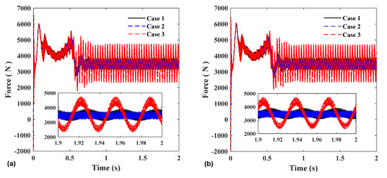
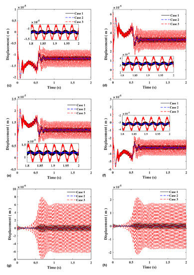
Figure 13.
(a) Gear1–3 mesh force; (b) Gear2–3 mesh force; (c) Gear 1 X-direction; (d) Gear 1 Y-direction; (e) Gear 2 X-direction; (f) Gear 2 Y-direction; (g) Gear 3 X-direction; and (h) Gear 3 Y-direction.
3.3. Influences of Inverter Power Supply on Vibration
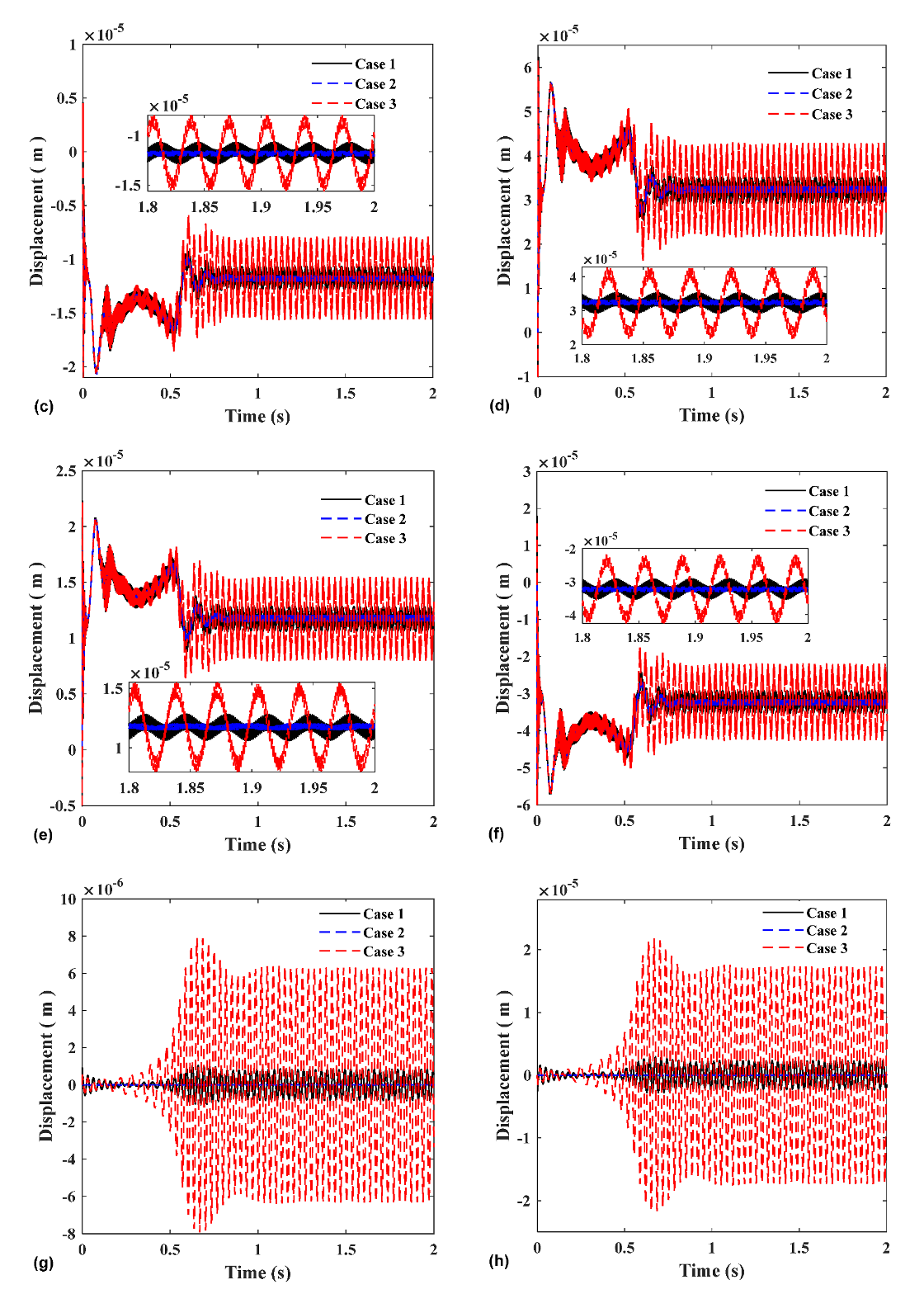
The rotational speed diagram of gear 1 is shown in Figure 14a. When using the variable frequency drive to start, the system enters the steady-state in 0.7 s, while when using the three-phase power supply to start directly, the system enters the steady-state time lag for 0.4 s, and in the steady-state stage, the steady-state speed of the variable frequency drive is smaller than that of the direct start. State speed, while the speed vibration of variable frequency drive is slightly larger than that of direct start.
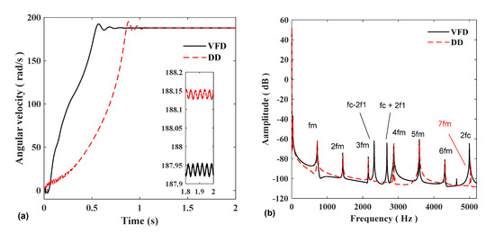
Figure 14.
Angular velocity of gear 1: (a) time domain; (b) frequency domain.
The frequency spectrum of the speed of gear 1 is shown in Figure 14b. Since the model uses an inverter, the harmonic components of variable frequency startup are more abundant than that of the direct startup. The frequency spectrum mainly includes the meshing frequency fm of gears 1–3 and 2–3, the double frequency 2fm, the triple frequency 3fm, etc., The frequency conversion start-up spectrum also includes the triangular carrier frequency domain fc generated by the inverter and the modulation frequency of the power supply fundamental frequency f1: there are also peaks at fc-2f1, fc + 2f1, and 2fc.
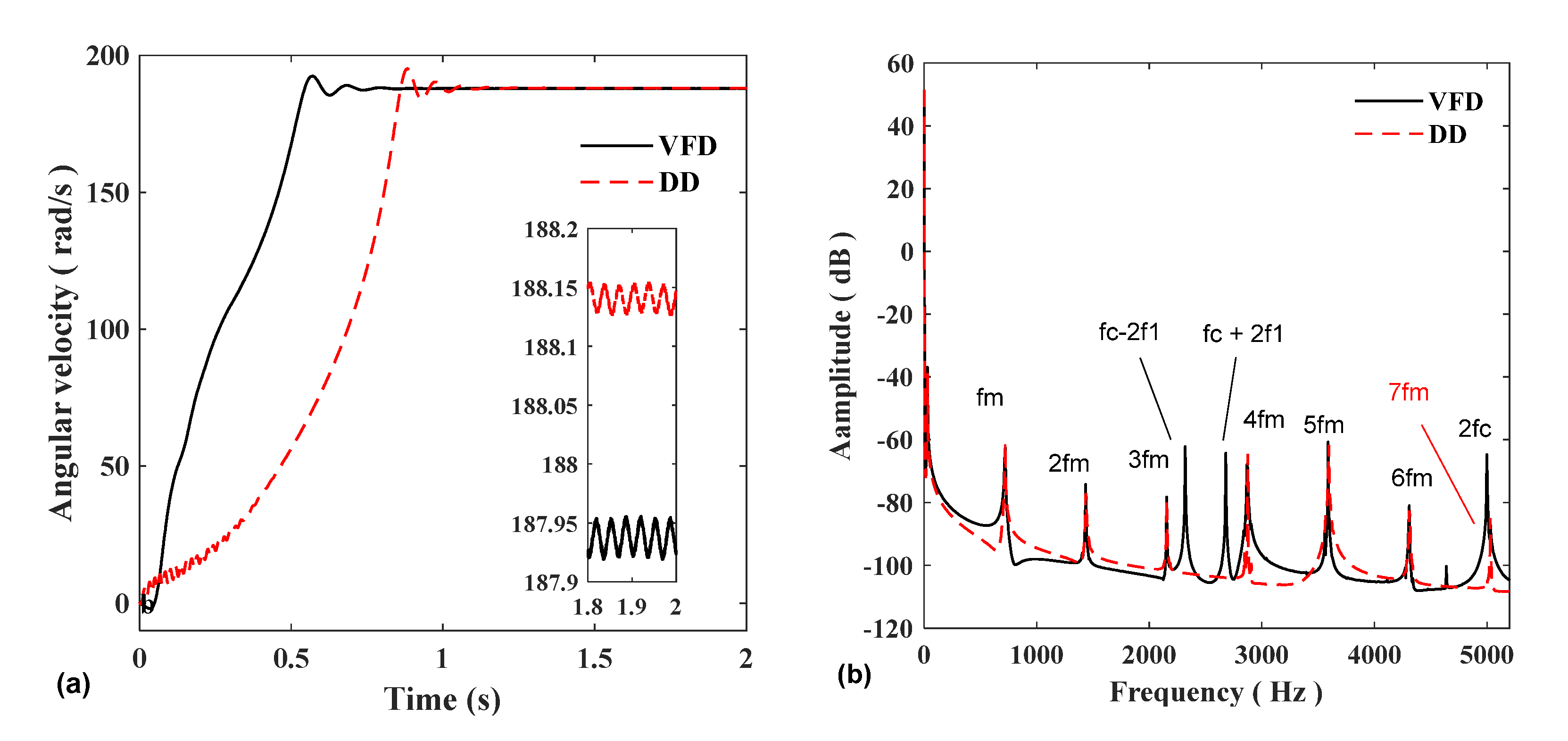
The time-domain and frequency-domain diagrams of the meshing force are shown in Figure 15. From the point of view of the time to enter the steady-state, the frequency conversion start time is shorter than the direct start time. From the perspective of force variation, the frequency conversion start amplitude is slightly larger than that of the direct start. The wave composition is roughly the same as the frequency spectrum of the tachogram, which indicates that the difference in amplitude in the time domain is caused by the inverter.
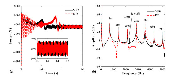
Figure 15.
Gear1−3 mesh force: (a) time domain and (b) frequency domain.
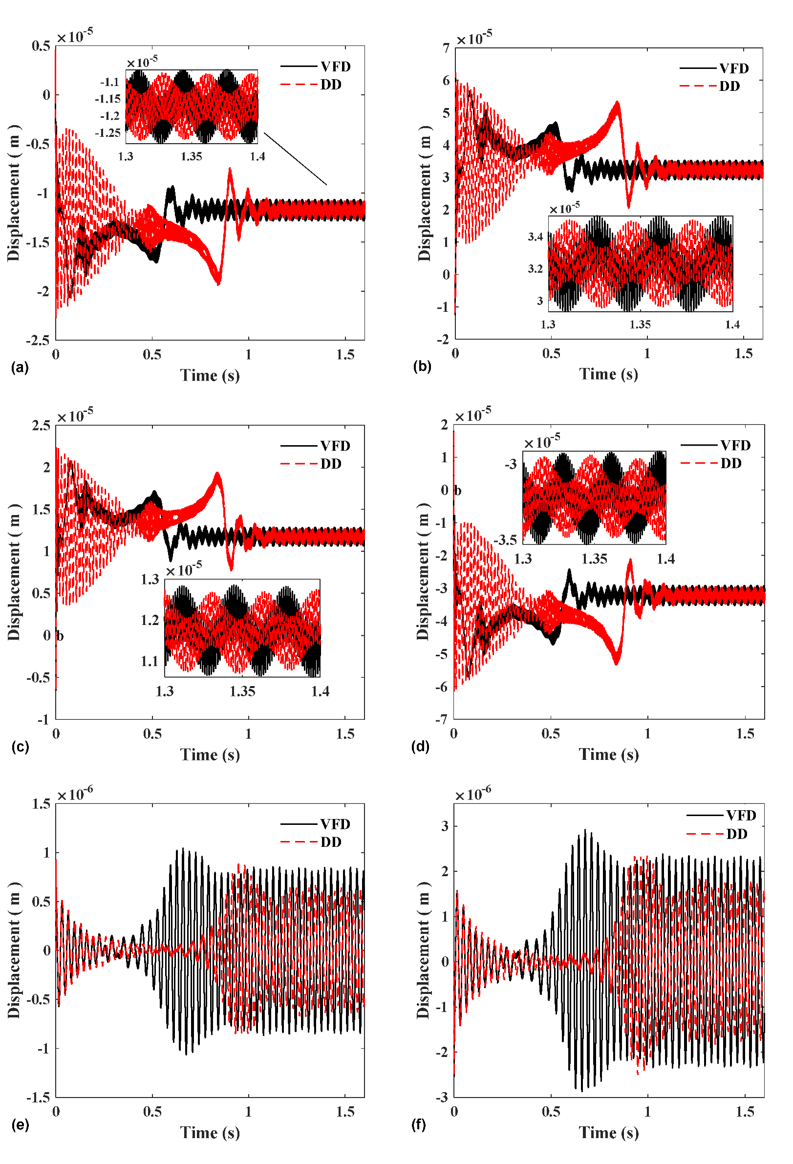
Figure 16 shows the displacement and vibration of gears 1, 2, and 3 on the horizontal and vertical components, respectively, which is consistent with the meshing force, indicating that the displacement during variable frequency startup is greater than that of the direct startup.

Figure 16.
(a) Gear 1 X-direction; (b) Gear 1 Y-direction; (c) Gear 2 X-direction; (d) Gear 2 Y-direction; (e) Gear 3 X-direction; and (f) Gear 3 Y-direction.
By comparing the vibration conditions of the corresponding parameters in Section 3.2 and Section 3.3, considering the error at the same time, the influence of variable frequency start-up and direct start-up on the vibration of each parameter in the steady-state is smaller than that of the error. As shown in Figure 17, comparing the case where the variable frequency start does not consider the comprehensive error and the direct start considers the error, we concluded that the influence of the error on the system vibration is greater than the influence of the power supply on the system vibration.
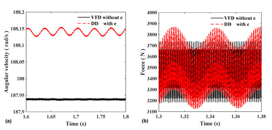
Figure 17.
(a) Gear 1 angular velocity and (b) gear 1–3 mesh force.
3.4. Influences of Coupling Stiffness on Vibration
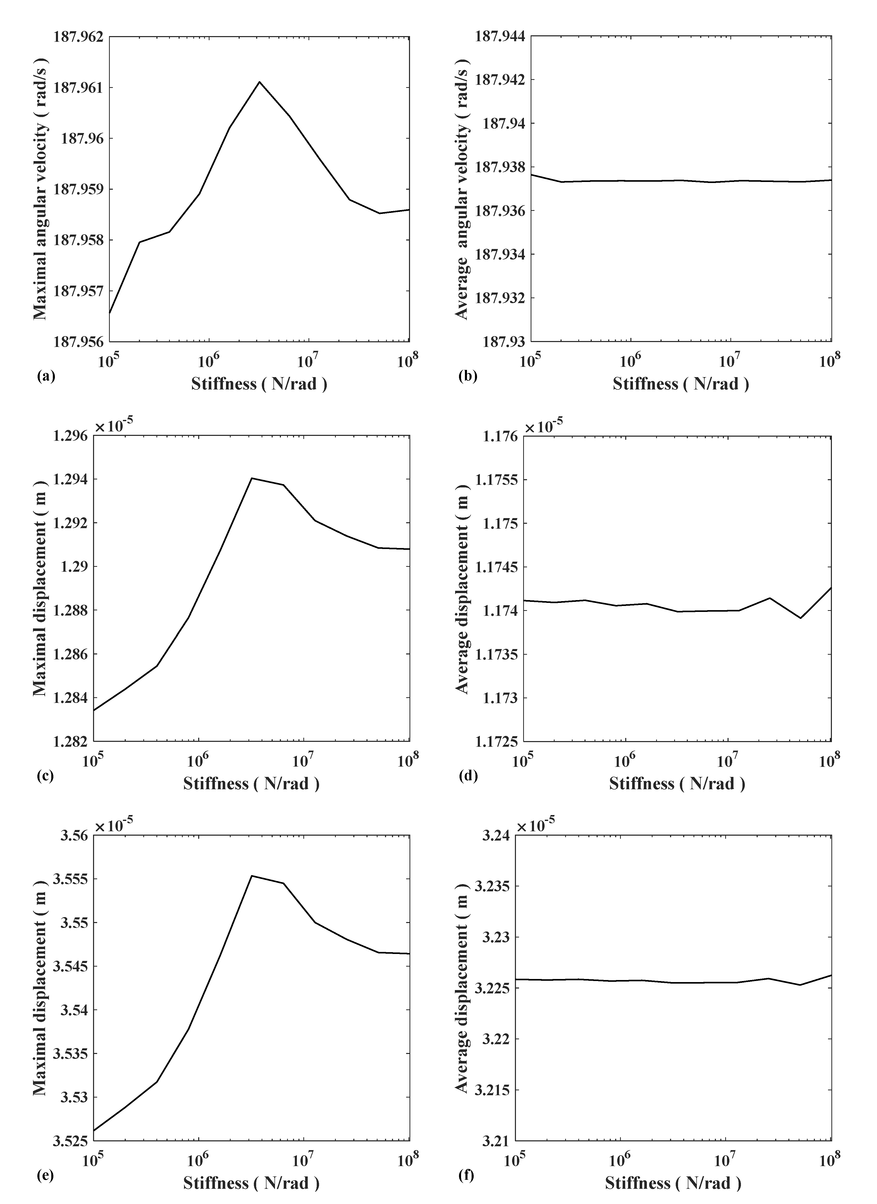
To study the effect of coupling stiffness on vibration, ten sets of data with torsional stiffness in the range of 105–108 were selected for simulation. After reaching the steady-state, the maximum value and average value of the rotational speed of gear 1 are shown in Figure 18a,b, and the maximum value and average value of the displacement in the X and Y directions of gear 1 are shown in Figure 18c–f. It can be seen from the average value image that the coupling stiffness had little effect on the steady-state DC component of the system but had a greater effect on the vibration. With the increase of coupling stiffness, the gear speed vibration first increased, then decreased, and finally increased, with a peak in the range of 106–107.
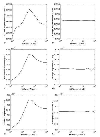
Figure 18.
(a) Gear1 maximal angular velocity; (b) Gear1 average angular velocity; (c) Gear1 X-direction maximal displacement; (d) Gear1 X-direction average displacement; (e) Gear1 Y-direction maximal displacement; and (f) Gear1 Y-direction average displacement.
This is because the change in stiffness makes the natural frequency close to the excitation frequency, resonance occurs, and the vibration of the gear speed rises sharply. When ignoring the effect of resonance, the greater the coupling stiffness is, the greater the system vibration.
4. Conclusions
In this study, an electromechanical coupling model, including inverter power supply, three-phase induction motor, fixed-axis gear, and the load, was established. The influences of the gear error, inverter, and coupling stiffness on the vibration characteristics of the system were studied, and the influence rules of various parameters on the vibration characteristics were analyzed.
When studying the influence of error on system vibration, we found that the larger the error of the gear, the greater the system vibration; the leading role in the error is the rotation frequency error instead of meshing frequency error; the greater the accuracy difference between the two input wheels, the greater the system vibration. By comparing the influence of error value and accuracy difference on vibration, we found that when an accuracy difference exists, the dominant factor of system vibration is the accuracy difference.
For the inverter-driven model, the harmonic components of the system were more complex due to the use of inverters. Although the model using the inverter reached a steady-state faster than the ideal three-phase voltage at start-up, there was more vibration at a steady state. When studying the effect of coupling stiffness, we found that with a greater coupling stiffness, the system vibration showed a trend of increasing first and then decreasing.
This is because when the stiffness was at medium stiffness, the change of coupling stiffness made the natural frequency of the system close to the excitation frequency, and resonance occurs, which makes the vibration intensifies. In order to avoid resonance of elastic coupling frequency with other elements in the ship, coupling with low stiffness is recommended to reduce the vibration of the system.
Author Contributions
Methodology, F.Y. and D.W.; software, D.W. and W.H.; formal analysis, L.H.; investigation, L.H. and W.H.; writing—original draft preparation, L.H.; writing—review and editing, F.Y. and W.H.; supervision, F.Y.; funding acquisition, F.Y. All authors have read and agreed to the published version of the manuscript.
Funding
The National Natural Science Foundation of China (No. 51775309) and the Key Technology Research and Development Project of Shandong Province (2019GGX104013).
Institutional Review Board Statement
Not applicable.
Informed Consent Statement
Not applicable.
Data Availability Statement
No new data were created or analyzed in this study. Data sharing is not applicable to this article.
Conflicts of Interest
The authors declare no conflict of interest.
References
- McCoy, T.J. Electric ships past, present, and future. IEEE Electrif. Mag. 2015, 3, 4–11. [Google Scholar] [CrossRef]
- Thongam, J.S.; Tarbouchi, M.; Okou, A.F.; Bouchard, D.; Beguenane, R. Trends in naval ship propulsion drive motor technology. In Proceedings of the IEEE Electrical Power and Energy Conference, EPEC, Halifax, NS, Canada, 21–23 August 2013; IEEE: Piscataway, NJ, USA, 2013. [Google Scholar]
- Qi, F.; Li, X.; Liu, G. Application of Hydraulic Transmission Device in Engineering Ship Field. Mod. Manuf. Technol. Equip. 2018, 1, 168–169. [Google Scholar]
- Wang, Z. The Gearbox Vibration Noise Analysis and Optimization Research. Bachelor’s Thesis, Harbin Engineering University, Harbin, China, 2018. [Google Scholar]
- Han, H.S.; Lee, K.H.; Park, S.H. Parametric study to identify the cause of high torsional vibration of the propulsion shaft in the ship. Eng. Fail. Anal. 2016, 59, 334–346. [Google Scholar] [CrossRef]
- Xiao, N.; Zhou, R.; Xu, X.; Lin, X. Study on vibration of marine diesel-electric hybrid propulsion system. Math. Probl. Eng. 2016, 2016, 8130246. [Google Scholar] [CrossRef] [Green Version]
- Zhang, Y.; Yan, X.; Lin, Q. Characteristic of torsional vibration of mill main drive excited by electromechanical coupling. Chin. J. Mech. Eng. 2016, 29, 80–187. [Google Scholar] [CrossRef]
- Yi, Y.; Qin, D.; Liu, C. Investigation of electromechanical coupling vibration characteristics of an electric drive multistage gear system. Mech. Mach. Theory 2018, 121, 446–459. [Google Scholar] [CrossRef]
- Shu, R.; Wei, J.; Tan, R. Investigation of dynamic and synchronization properties of a multi-motor driving system: Theoretical analysis and experiment. Mech. Syst. Signal Process. 2021, 153, 107496. [Google Scholar] [CrossRef]
- Xiao, N.; Zhou, R.; Xu, X.; Lin, X. Research on Marine Electric Propulsion Shafting under Electromechanical Coupling Condition. Appl. Mech. Mater. 2014, 607, 477–482. [Google Scholar] [CrossRef]
- Jiang, S.; Li, W.; Wang, Y.; Yang, X.; Xu, S. Study on electromechanical coupling torsional resonance characteristics of gear system driven by PMSM: A case on shearer semi-direct drive cutting transmission system. Nonlinear Dyn. 2021, 104, 1205–1225. [Google Scholar] [CrossRef]
- Wen, Y.; Qin, D.; Wang, Y.; Lim, T.C. Dynamic characteristic of electromechanical coupling effects in motor-gear system. J. Sound Vib. 2018, 423, 50–64. [Google Scholar]
- Zhang, Y.; Yan, X.; Lin, Q. Electromechanical coupling vibration of rolling mill excited by variable frequency harmonic. Adv. Mater. Res. 2014, 912, 662–665. [Google Scholar] [CrossRef]
- Chen, X.; Han, S.; Li, J.; Deng, T.; Wei, H. Investigation of electromechanical coupling lateral/torsional vibration in a high-speed rotating continuous flexible shaft of PMSM. Appl. Math. Model. 2020, 77, 506–521. [Google Scholar] [CrossRef]
- Szolc, T.; Konowrocki, R.; Michajłow, M.; Pręgowska, A. An investigation of the dynamic electromechanical coupling effects in machine drive systems driven by asynchronous motors. Mech. Syst. Signal Process. 2014, 49, 118–134. [Google Scholar] [CrossRef]
- Lysenko, O.A.; Simakov, A.V. The pump hydraulic load effect determination on the parameters of an frequency-controlled asynchronous electric drive. In Proceedings of the 2019 Dynamics of Systems, Mechanisms and Machines, Omsk, Russia, 5–7 November 2019; IEEE: Piscataway, NJ, USA, 2019; pp. 1–6. [Google Scholar]
- Bilgin, B.; Liang, J.; Terzic, M.V.; Dong, J.; Rodriguez, R.; Trickett, E.; Emadi, A. Modeling and analysis of electric motors: State-of-the-art review. IEEE Trans. Transp. Electrif. 2019, 5, 602–617. [Google Scholar] [CrossRef] [Green Version]
- Peng, H. Torsional Vibration Analysis and Optimization of Heavy-Duty High-Power and High-Elastic Coupling. Bachelor’s Thesis, Sichuan University, Chengdu, China, 2021. [Google Scholar]
- Diaz, A. Induction motor equivalent circuit for dynamic simulation. In Proceedings of the 2009 IEEE International Electric Machines and Drives Conference, Miami, FL, USA, 3–6 May 2009; IEEE: Piscataway, NJ, USA, 2019. [Google Scholar]
- Li, H.; Wang, C.; Guo, H.; Liu, Y.; Bao, F.; Zhang, Z. Simulation research on Motion Control System of Marine Propulsion Motor. Ship Sci. Technol. 2020, 13, 114–119. [Google Scholar]
- Wang, D.; Yang, F.; Jiang, X.; Shi, S.; Ma, S. Electromechanical Coupling Dynamic Characteristics of Differential Speed Regulation System Considering Inverter Harmonics Under Variable Operating Conditions. IEEE Access 2022, 10, 12057–12069. [Google Scholar] [CrossRef]
- Gou, B.; Xu, Y.; Xia, Y.; Deng, Q.; Ge, X. An online data-driven method for simultaneous diagnosis of IGBT and current sensor fault of three-phase PWM inverter in induction motor drives. IEEE Trans. Power Electron. 2020, 35, 13281–13294. [Google Scholar] [CrossRef]


Publisher’s Note: MDPI stays neutral with regard to jurisdictional claims in published maps and institutional affiliations. |
© 2022 by the authors. Licensee MDPI, Basel, Switzerland. This article is an open access article distributed under the terms and conditions of the Creative Commons Attribution (CC BY) license (https://creativecommons.org/licenses/by/4.0/).