Abstract
In this paper, a structural design and controller optimization process for a five-bar planar manipulator are studied using three different population-based optimization techniques: particle swarm optimization, genetic algorithm, and differential evolution. First, the desired kinematic properties of the manipulator, such as the position, velocity, and acceleration of the endpoint, are determined using inverse kinematics. Then, an optimization problem is created to minimize the shaking force and moments, and the desired kinematic quantities are implemented as constraints. All the link properties of the manipulator are defined as design variables, and the optimization results are obtained. The results show that it is possible to significantly reduce the shaking force and moment significantly thanks to the optimal design parameters. Finally, the controller is optimized to find the best PID gains considering the forward kinematics of the manipulator. It is observed that the shaking force and shaking moment can be reduced by 99% and 54%, respectively, which has a very positive effect on the accuracy of the trajectory tracking. Moreover, the performances of the optimization methods are compared by using the same number of iterations in the calculations, and thus, it can be seen that the GA method achieves the best results compared to the others. Therefore, the results of this study are of utmost importance for a manufacturer, who wants to design a five-bar planar manipulator and its controller.
1. Introduction
In the last two decades, five-bar planar manipulators have been extensively used in various industrial fields, especially in robotic applications for mass production such as assembly, transportation, and positioning, as well as haptic and medical devices. There are a variety of five-bar planar manipulators depending on whether the actuators are rotary or linear [1].
In designing such a mechanism, several problems related to kinematics and dynamics must be solved. The determination of workspace (including singularity points) and trajectory planning are the main kinematic issues [1,2,3,4,5,6,7,8,9,10,11,12,13], while determination and minimization of the shaking forces and torques, together with the torques of the actuators, are the crucial dynamic issues [14,15,16,17,18,19,20,21,22,23]. In [2,3], the singularity and workspace of the 5R (revolute joint) symmetrical parallel mechanism are studied. Cervantes et al. found all the working space and singularity curves of a 2-DOF, 5R manipulator [2]. On the other hand, X.-J. Liu et al. determined the optimal design criteria for the maximum working space, which is only suitable for working conditions with an upward configuration [3]. Stan et al. [6] addressed a kinematic optimization problem for a microparallel RPRPR robot (two linear actuators and three revolute joints). In their kinematic optimization, the most suitable dimensions of the bipod model were found for the largest workspace.
For fast-moving parallel mechanisms, trajectory planning is also of great importance. Oarcea et al. [10] studied two motion profiles (constant velocity and trapezoidal velocity) using the Dassault Systems Solidworks and Simulink Simscape Multibody Software. In [11,12], the integration of non-circular gears is specifically used to operate on only one precise trajectory. In particular, in [11], the dimensions of a five-bar mechanism were obtained by genetic optimization as a function of the trajectory. Uzunoglu et al. [13] integrated the five-bar mechanism into laser-cutting machines to accelerate short movements. They designed a new algorithm by adding the U and V axes to the five-bar mechanism, in addition to the X and Y main axes, to the G-codes, which is known as the communication language of the CNC systems.
High-speed mechanisms are designed to eliminate or minimize shaking forces and shaking moments. Berkoff [14] has shown that an inertial counterweight and a physical pendulum joint can provide a complete balance of force and moment for a specific case of inline joints. In addition, the conditions for redistribution of mass and the inclusion of additional masses required to fully balance the inertial loads of the linkage were determined.
Alici and Shirinzadeh [17] analyzed the dynamic equilibrium of the five-bar linkage to optimize the sum of squared values of the bearing forces, driving torques, shaking moment, and the sum of angular momentum by considering the lengths and angles of the mechanism. Ilia and Sinatra [20] used a novel simplified approach for the dynamic balancing of five-bar linkages. They derived the dynamic model of the five-bar mechanism by restoring the natural-orthogonal complement method and then determined the shaking force acting in the workspace. A system of seven equations and four inequality constraints with twelve linkage parameters expressed the dynamic balancing conditions of the five-bar linkage.
The population-based optimization methods are very effective tools for determining the correct kinematic and dynamic parameters of the mechanism. The most commonly used stochastic optimization methods in the literature are the genetic algorithm (GA), particle swarm optimization (PSO), and differential evolution (DE). These methods have numerous applications regarding the mechanism and machine design [24,25,26,27,28,29,30,31,32,33,34,35]. Yildiz [28] used these methods to optimize the four-bar linkages used in the mechanism to open and close the trunk lid of sedans. Sergiu, Maties, and Balan [9] solved an optimization problem using a genetic algorithm to create the largest workspace; as a result, they determined the symmetric link length. Alici and Shirinzadeh [18] used a genetic algorithm for the dynamic balancing of the five-bar linkage. In their study, they determined which components were more important in the objective function by giving the weight factors the value “0” or “1”.
In practice, the control of a manipulator is also an important issue. Among the numerous works in this field, some important ones related to the present work will be mentioned here. In [36], the prototype of a planar parallel manipulator with five-bars was created by a multi-disciplinary study, and the simulation results were compared with the measurement results by performing the PI control. Tao and Sadler [37] developed the constant speed control of a four-bar mechanism driven by a motor using a state-space representation, and several modified PID-type rules were implemented. In recent years, various control algorithms seem to work together or nested. [38,39,40]. In [40], the extreme learning machine-PID controller has shown that it outperforms the pure P and PID controllers with the adaptive tuning of the control parameters. Optimization methods such as GA [38] and PSO [39] are used, especially to select the coefficients of the widely used PID controller. In this study, the gains of the PID controllers are determined using an optimization technique after solving the problem of balancing the shaking forces and moments.
This work differs from the previous studies in three aspects. First, in solving the balancing problem of the manipulator, all the properties of the joints, such as the lengths, masses, inertias, and centers of gravity of the bars, are considered optimization parameters. Second, in this optimization problem, the largest desired trajectory is tracked in the reachable workspace (without singularity) with the constraint functions. Third, the PID gains of the developed controller are also obtained by optimization. The balancing and control of the manipulator could be posed as a single multi-objective optimization problem. However, the combination of these two stages of the problem could make the optimization algorithm become more complicated. Hence, the manipulator control problem was defined as a secondary optimization problem. The layout of the simulation of the optimization algorithms has seen in Figure 1. Three different optimization techniques have been used to compare their performances for both optimization problems.
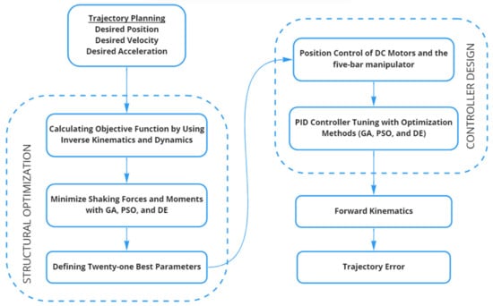
Figure 1.
The layout of the simulation of the optimization algorithm.
2. Modeling of the Five-Bar Planar Manipulator
The general view of the five-bar manipulator used in this paper is illustrated in Figure 2. Provided that the physical features and positions of the links and the desired motion profile of point P are known, the angular position, velocity, and acceleration values are determined from inverse kinematic analysis.
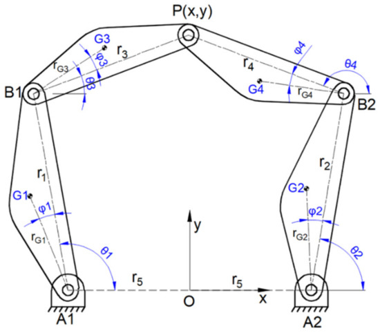
Figure 2.
The five-bar manipulator.
2.1. Inverse Kinematics of the Five-Bar Planar Manipulator
The loop equation of the five-bar manipulator can be written as follows:
or in form of complex numbers,
In the above equations, ri (i = 1…5) denote the lengths of the links and θi (i = 1…4) their rotation angles. Besides, the terms x and y define the position of point P. The solution of the inverse kinematic problem can be expressed with the following equations:
where θ1 and θ2 are the input angles of the mechanism. These are obtained from either Equations (4) and (5):
where
in which
Five-bar planar parallel manipulators have four inverse kinematics solutions [3]. These solution configurations have (+ −), (+ +), (− −), and (− +) models according to the sign of (σ1 σ2) values. In this paper, the inverse kinematics solution is obtained by considering the operation in the (+ −) model; that is, σ1 = + 1 and σ2 = −1 are taken. θ3 and θ4 are obtained by substituting the values of θ1 and θ2 in Equations (2) and (3).
The relationship between the link angular velocities and the linear velocity components of point P is given by the following matrix equation:
where ωi (i = 1…4) are links’ angular velocities. Vx and Vy are the x- and y-components of point P.
Similarly, the angular accelerations are given as follows:
where αi (i = 1…4) are links’ angular accelerations. ax and ay are linear acceleration components of point P in the x- and y-directions. The accelerations of the center of gravities can be obtained as follows:
where rgi and φi (i = 1…4) are the magnitudes and orientation angles of the local position vectors of the centers of gravity.
2.2. Inverse Dynamics of the Five-Bar Planar Manipulator
In this part, to determine the shaking forces and moments transmitted to the machine foundation, the dynamic analysis of the mechanism is carried out by using the well-known Newton–Euler principle. The free-body diagrams are given in Figure 3.
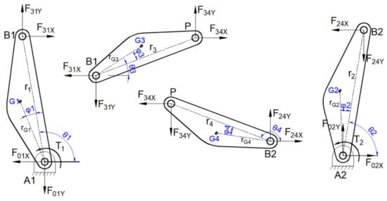
Figure 3.
Free body diagrams of the five-bar planar manipulator.
The following equations of motion are written for link 1:
where
Substituting Equations (15) and (16) in Equation (14) yields the following equation:
Similar equations must be written for other links. All the equations of motion are given in the matrix form (Appendix A). The number of motion equations is twelve. It should be noted that the dynamic equations of the system are derived by considering zero friction conditions.
2.3. Shaking Force and Moment of the Five-Bar Planar Manipulator
The five-bar manipulator is connected to the ground at two fixed pivot points, A1 and A2. The sum of the forces transmitted to the ground via the fixed joints is defined as the shaking force. This shaking force is given in Equation (20).
The shaking moment transmitted to the ground is as follows:
3. Structural Optimization of Five-Bar Planar Manipulator
3.1. Desired Trajectory Planning
The largest circular trajectory in two-dimensional space is assumed to be tracked by point P in the reachable workspace (no singular points), as illustrated in Figure 4.
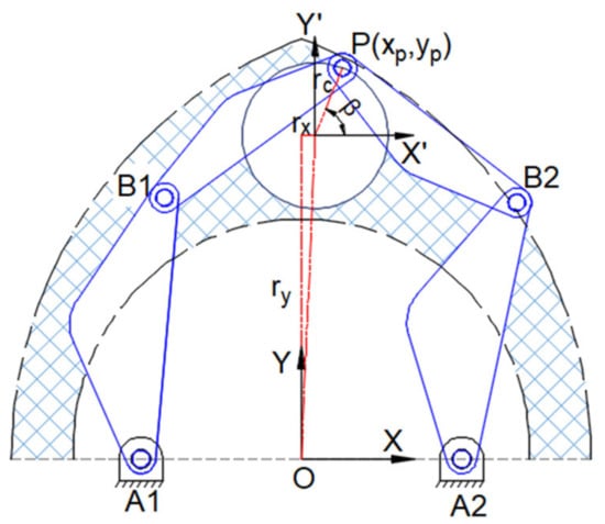
Figure 4.
Applied trajectory.
The trapezoidal motion program is one of the most widely used motions in industrial robots. In the trapezoidal velocity profile, the endpoint P moves with maximum constant velocity during most of the operation time. The desired motion profile equations are presented in Equations (22)–(24).
The trajectory is comprised of three main parts, as shown in Figure 5a. These plots represent the angular position, angular velocity, and angular acceleration of the endpoint P. For a circular trajectory, the endpoint P position, velocity, and acceleration according to the motion as defined in Figure 5a are given in Figure 5b.
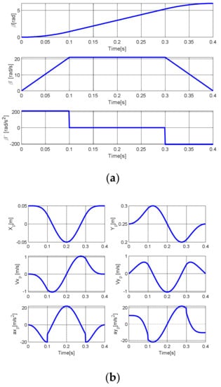
Figure 5.
(a) The trapezoidal motion profile, (b) position, velocity, and acceleration of the endpoint P.
3.2. Definition of the Objective Function, Design Variables, and Constraints
The optimization problem can be defined as re-dimensioning the five-bar manipulator such that the shaking forces and shaking moments become minimized while following the desired trajectory. The objective function is selected as follows:
where and are the weighting factors, and are the first and second objective functions, respectively. The weighting factors’ sum should be equal to one. The first objective function is the sum of the absolute values of shaking force, while the sum of the absolute shaking moment is the second objective function.
This object function includes twenty-one design variables given in the following:
The constraint functions contain keeping the desired trajectory within the workspace and balancing the five-bar manipulator.
where g1 and g2 are the equations of the outer circle of the workspace. g3 and g4 show the singularity created by the locus of point P when B1PB2 is completely extended. Other functions are related to mass balancing.
In order to limit the solution space, the following constraints are also added to the above-mentioned ones.
3.3. Applied Optimization Methods
In this study, we have used three optimization procedures. These were, namely, genetic algorithm (GA) [36], particle swarm optimization (PSO) [37], and differential evolution (DE) [38,39]. GA procedure is inspired by reproduction processes and natural selection. This method aims to solve the extremum problems with a randomly generated population of individuals called chromosomes. GA reproduces new generations of those chromosomes by considering the natural selection approach, which can be summarized as survival of the fittest. The PSO method, which is a stochastic optimization algorithm, was inspired by the group behavior of birds and fishes. In this method, a random group of particles is submitted to search for the extreme point of the objective function. Then, the particles follow the nearest ones to obtain the best value of the target through the reproduced velocities. This process continues until the final criteria are satisfied. DE algorithm uses real numbers to represent each variable’s value. Its speed, tenacity, and basic structure are the most important assets of this method. Equations of the PSO and DE methods are given in Appendix B.
For each optimization method, the objective function is calculated until the maximum number of iterations is reached and the best solution is found. The pseudocode and parameters of the optimization methods are given in Table 1.

Table 1.
Optimization pseudo-codes and the optimization parameters.
3.4. Structural Optimization Results
In this optimization study, the objective functions are solved using different weighting factors according to a single objective function. Table 2 shows the sum of the absolute values of shaking force and shaking moment according to the change of weighting factors using three different optimization methods.
Table 2.
The total objective function for different weighting factors for three methods.
When the multi-objective function is used singularly, the best result is determined in two ways. First, by displaying the objective function one versus function two on a graph, the closest value to the origin can be chosen. Secondly, the minimum value can be found by taking the square root of the sum of the squares of the objective functions. The graphical representation of the obtained objective function one and objective function two values are given in Figure 6.
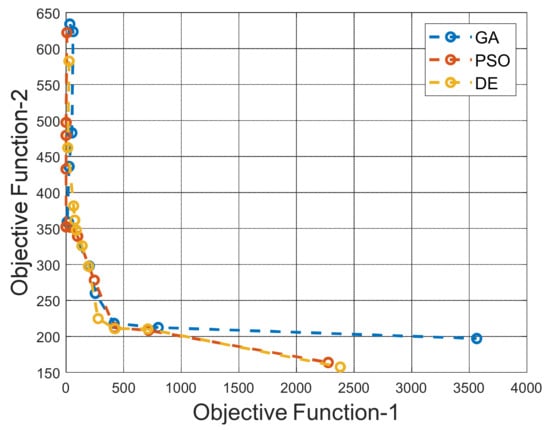
Figure 6.
Relationship between number values of two objective functions.
The PSO method using = 0.6 and = 0.4 as the weighting factors gives the best results. The change in the design variables, which yields these results is shown in Table 3.
Table 3.
The change in design variables.
While following the circular trajectory, the shaking force, shaking moment, and driving torques in the initial state, and after optimization are shown in Figure 7.
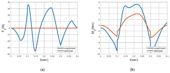
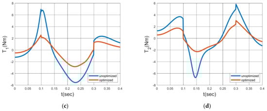
Figure 7.
Results of optimization: shaking force (a), shaking moment (b), driving torque 1 (c), and driving torque 2 (d).
A reduction of 99.99% in the sum of the absolute values of the shaking force, 54.44% in the sum of the absolute values of the shaking moment, 52.56% in the sum of the absolute values of the first driving torque, and 48.54% in the sum of the absolute values of the second driving torque have been determined.
4. Controller Design
As mentioned above, the control of a manipulator is essential to practical applications. Therefore, this section is devoted to the design of the controller based on the PID algorithm. The block diagram of this system is presented in Figure 8.
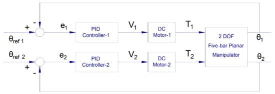
Figure 8.
Block diagram of PID controlled system.
The equations of motion of the manipulator are obtained using the Lagrange method. The angles of the driving links and are defined as active joint angles, while the angles and are called passive joint angles. The passive angles can be expressed as the functions of active angles as follows:
The influence coefficients of the angular velocities and angular accelerations of the passive angles are shown in Equations (32) and (33) as follows:
Considering and as principal generalized coordinates, Lagrange’s equations can be written as follows:
where is kinetic energy and are input torques.
The kinetic energy is expressed as follows:
4.1. Mathematical Model of DC Motor
The mathematical model of the DC gear motor is specified in the following equations:
where , in Equation (38), , , , and is input voltage
where , , TL in Equation (39), , , TL is constant mechanical load and is system output torque. DC gear motor properties in Table 4.
Table 4.
Motor properties.
Substituting Equations (36) and (37) in Equation (39) yields
State variables are defined as follows:
Equations (38), (40) and (41) in the state-space form become as follows:
4.2. Tuning of PID Controller Using Optimization Methods
Since the five-bar manipulator system with two DC motors is nonlinear, numerical optimization methods are used to determine the PID controller gains. The following objective function is used to find their optimal gain:
where and are the integral absolute errors. These are given in Equations (45) and (46). Angular position values in inverse kinematics are used as reference position values.
Here, optimization aims to minimize the position errors of the motors in the five-bar manipulator. Optimized PID coefficients give the minimum position error in a trajectory.
Tuning the PID gains is a very important issue, and there are different methods to find them. In our study, they will be obtained by using population-based algorithm methods. The PID gains (Kp1, Kd1, Ki1, Kp2, Kd2, Ki2) are defined as design variables, and their ranges are as follows:
4.3. PID-Controller Simulation Results
The center of the circular trajectory chosen is (xc, yc) = (0 m, 0.25 m), and the circle radius is rc = 0.50 m. The center is chosen so that there is no singularity.
The PID gains obtained after the optimization procedures are shown in Table 5.
Table 5.
PID gains.
The angular positions of the motors and the trajectory obtained by applying PID gains are shown in Figure 9.
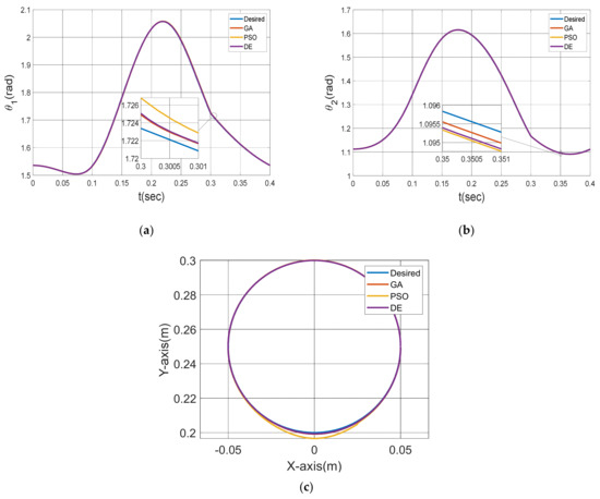
Figure 9.
Control results, first motor angle (a) and second motor angle (b), applied trajectory (c).
5. Conclusions
This study focuses on finding the design parameters that minimize the shaking force and moment and provide the most accurate trajectory tracking with PID position control. To achieve this, the largest trajectory to follow was identified. In the meantime, the desired maximum working speed and acceleration values were determined.
First, the objective function of structural optimization consists of two objective functions. A single objective function is created by applying the weighting factor. Optimization is performed using GA, PSO, and DE. Here, different results are obtained such that the sum of the weighting factor values is one. When all the results are compared, the optimum design is found using the PSO method and giving = 0.6 and = 0.4. The shaking force is balanced, and the shaking moment is minimized.
Secondly, there are two objective functions when finding the PID Controller gains by optimization. Here, the square root of the sum of the squares of IAE1 and IAE2 is converted to a single objective function. Consistent results are obtained without applying the weighting factor. The most accurate trajectory tracking is found with GA optimization.
The application of these three different optimization methods shows that different optimization methods give better results in various optimization problems.
Author Contributions
Conceptualization, D.K.S., A.Y. and O.K.; methodology, D.K.S., O.K.; software, D.K.S.; validation, D.K.S., A.Y. and O.K.; formal analysis, D.K.S. and A.Y.; investigation, D.K.S. and O.K.; resources, D.K.S.; data curation, O.K.; writing—original draft preparation, D.K.S.; writing—review and editing, D.K.S., A.Y., and O.K.; visualization, D.K.S.; supervision, O.K. All authors have read and agreed to the published version of the manuscript.
Funding
This research received no external funding.
Conflicts of Interest
The authors declare no conflict of interest.
Appendix A
The five-bar planar manipulator dynamic equations in matrix form are shown in Equation (A1)
where .
Appendix B
Equations of PSO method;
where i = 1,2,… N, and N refers to the swarm size, k = 1,2,…K, and K refers to the maximum number of iterations, V is the particle velocity, P is the position of the particle, PPB is the best position of particles and PGB is the global best of the swarm. r1 and r2 are random numbers between (0,1), c1 and c2 are the cognitive and global acceleration factors.
Equations of DE algorithm;
Initialization population vector:
where bL and bU are initialization vectors, L and U are the lower and upper bounds.
Mutant vector:
where F is the mutation factor r0 is the base vector index, r1 and r2 are the difference vector indices. r0, r1 and r2 are randomly selected per mutant.
Crossover:
where CR is crossover constant , i is the size of population, j is variable size, xi,G is target vector and ui,G is the trial vector.
Selection:
Appendix C
Representation of the Lagrangian equations in terms of active angles, active velocity, and active accelerations;
Velocity coefficients:
Total kinetic energy:
If the total kinetic energy is written in terms of active speeds:
Lagrangian equations:
The coefficients ki and li representation in Equations (32) and (33) are below. (i = 1…5)
Abbreviations applied here;
References
- Cervantes-Sánchez, J.J.; Rendón-Sánchez, J.G. Simplified approach for obtaining the workspace of a class of 2-dof planar parallel manipulators. Mech. Mach. Theory 1999, 34, 1057–1073. [Google Scholar] [CrossRef]
- Cervantes-Sánchez, J.; Hernández-Rodríguez, J.; Rendón-Sánchez, J. On the workspace, assembly configurations and singularity curves of the RRRRR-type planar manipulator. Mech. Mach. Theory 2000, 35, 1117–1139. [Google Scholar] [CrossRef]
- Liu, X.-J.; Wang, J.; Pritschow, G. Kinematics, singularity and workspace of planar 5R symmetrical parallel mechanisms. Mech. Mach. Theory 2006, 41, 145–169. [Google Scholar] [CrossRef]
- Alıcı, G. Determination of singularity contours for five-bar planar parallel manipulators. Robotica 2000, 18, 569–575. [Google Scholar] [CrossRef]
- Liu, X.-J.; Wang, J.; Zheng, H.-J. Optimum design of the 5R symmetrical parallel manipulator with a surrounded and good-condition workspace. Robot. Auton. Syst. 2006, 54, 221–233. [Google Scholar] [CrossRef]
- Stan, S.; Lăpuşan, C. Workspace analysis of a 2 dof mini parallel robot. In Proceedings of the 8th National Symposium with International Participation COMPUTER AIDED DESIGN-PRASIC’06, Braşov, Romania, 9–10 November 2006; pp. 175–180. [Google Scholar]
- Liu, X.-J.; Wang, J.; Pritschow, G. On the optimal kinematic design of the PRRRP 2-DoF parallel mechanism. Mech. Mach. Theory 2006, 41, 1111–1130. [Google Scholar] [CrossRef]
- Campos, L.; Bourbonnais, F.; Bonev, I.A.; Bigras, P. Development of a Five-Bar Parallel Robot with Large Workspace. Proc. ASME Des. Eng. Tech. Conf. 2010, 2, 917–922. [Google Scholar] [CrossRef]
- Stan, S.-D.; Maties, V.; Bal, R. Optimal Design of Parallel Kinematics Machines with 2 Degrees of Freedom. Parallel Manip. Towar. New Appl. 2008, 14, 1–29. [Google Scholar] [CrossRef][Green Version]
- Oarcea, A.; Cobilean, V.; Stan, S.-D. Trajectory planning of a 3-RRRRR planar parallel robot. In Proceedings of the 2021 9th International Conference on Modern Power Systems (MPS), Cluj-Napoca, Romania, 16–17 June 2021; pp. 1–6. [Google Scholar] [CrossRef]
- Mundo, D.; Gatti, G.; Dooner, D. Optimized five-bar linkages with non-circular gears for exact path generation. Mech. Mach. Theory 2009, 44, 751–760. [Google Scholar] [CrossRef]
- Mundo, D.; Gatti, G.; Dooner, D.B. Combined synthesis of five-bar linkages and non-circular gears for precise path generation. In Proceedings of the 12th IFToMM World Congr., Besançon, France, 17–21 June 2007. [Google Scholar]
- Uzunoglu, E.; Dede, M.; Kiper, G. Trajectory planning for a planar macro-micro manipulator of a laser-cutting machine. Ind. Robot 2016, 43, 513–523. [Google Scholar] [CrossRef]
- Berkoff, R.S. Complete force and moment balancing of inline four-bar linkages. Mech. Mach. Theory 1973, 8, 397–410. [Google Scholar] [CrossRef]
- Elliott, J.L.; Tesar, D. The theory of torque, shaking force and shaking moment balancing of four link mechanisms. Trans. ASME J. Eng. Ind. 1977, 97, 715–722. [Google Scholar] [CrossRef]
- Acevedo, M.; Orvananos, T.; Velazquez, R.; Haro, E. Optimum Balancing of the Four-Bar Linkage Using Fully Cartesian Coordinates. IEEE Lat. Am. Trans. 2019, 17, 983–990. [Google Scholar] [CrossRef]
- Alici, G.; Shirinzadeh, B. Optimum dynamic balancing of planar parallel manipulators. In Proceedings of the 2004 IEEE International Conference on Robotics & Automation, New Orleans, LA, USA, 26 April–1 May 2004. [Google Scholar] [CrossRef]
- Alici, G.; Shirinzadeh, B. Optimum dynamic balancing of planar parallel manipulators based on sensitivity analysis. Mech. Mach. Theory 2006, 41, 1520–1532. [Google Scholar] [CrossRef]
- Nehemiah, P.; Sundara Siva Rao, B.S.K.; Ramji, K. Shaking force and shaking moment balancing of planar mechanisms with high degree of complexity. Jordan J. Mech. Ind. Eng. 2012, 6, 17–24. [Google Scholar]
- Ilia, D.; Sinatra, R. A novel formulation of the dynamic balancing of five-bar linkages with applications to link optimization. Multibody Syst. Dyn. 2009, 21, 193–211. [Google Scholar] [CrossRef]
- Alici, G.; Shirinzadeh, B. Optimum force balancing with mass distribution and a single elastic element for a five-bar parallel manipulator. In Proceedings of the 2003 IEEE International Conference on Robotics and Automation (Cat. No.03CH37422), Taipei, Taiwan, 14–19 September 2003; Volume 3, pp. 3666–3671. [Google Scholar] [CrossRef]
- Shaking Force Balancing of Planar Linkages with Force Transmission Irregularities Using Balancing Idler Loops—Science Direct. [Online]. Available online: https://www.sciencedirect.com/science/article/abs/pii/0094114X79900132 (accessed on 24 January 2021).
- Acevedo, M.; Orvañanos-Guerrero, M.T.; Velázquez, R.; Arakelian, V. An Alternative Method for Shaking Force Balancing of the 3RRR PPM through Acceleration Control of the Center of Mass. Appl. Sci. 2020, 10, 1351. [Google Scholar] [CrossRef]
- McCall, J. Genetic algorithms for modeling and optimization. J. Comput. Appl. Math. 2005, 184, 205–222. [Google Scholar] [CrossRef]
- Eberhart, R.C.; Kennedy, J. A new optimizer using particle swarm theory. In Proceedings of the 6th international symposium on micro machine and human science, Nagoya, Japan, 13–16 March 1995; pp. 39–43. [Google Scholar]
- Mayer, D.; Kinghorn, B.; Archer, A. Differential evolution—An easy and efficient evolutionary algorithm for model optimisation. Agric. Syst. 2005, 83, 315–328. [Google Scholar] [CrossRef]
- Gosselin, C.; Angeles, J. A global Performance Index for the Kinematic Optimization of Robotic Manipulators. J. Mech. Des. 1991, 113, 220–226. [Google Scholar] [CrossRef]
- Yildiz, A. Parametric synthesis of two different trunk lid mechanisms for sedan vehicles using population-based optimisation algorithms. Mech. Mach. Theory 2021, 156, 104130. [Google Scholar] [CrossRef]
- Le, T.D.; Kang, H.-J.; Doan, Q.V. A method for optimal kinematic design of five-bar planar parallel manipulators. In Proceedings of the 2013 International Conference on Control, Automation and Information Sciences (ICCAIS), Nha Trang, Vietnam, 25–28 November 2013; pp. 7–11. [Google Scholar] [CrossRef]
- Stan, S.; Vistrian, M.; Balan, R. Optimal Design of a 2 DOF Micro Parallel Robot Using Genetic Algorithms. In Proceedings of the 2007 IEEE-ICIT 2007, IEEE International Conference on Integration Technology, Shenzhen, China, 20–24 March 2007; pp. 719–724. [Google Scholar] [CrossRef]
- Ganesh, S.S.; Rao, A.K. Kinematic and Dynamic Optimization of a 2-DOF Parallel Kinematic Mechanism. Procedia Comput. Sci. 2018, 133, 576–584. [Google Scholar] [CrossRef]
- Bingul, O.; Yildiz, A. Fuzzy logic and proportional integral derivative based multi-objective optimization of active suspension system of a 4×4 in-wheel motor driven electrical vehicle. J. Vib. Control 2022, 10775463211062691. [Google Scholar] [CrossRef]
- Yildiz, A. Optimum suspension design for non-linear half vehicle model using particle swarm optimization (PSO) algorithm. In Proceedings of the 41st International JVE Conference Vibration, Leipzig, Germany, 30 September 2019. [Google Scholar]
- Yildiz, A.; Yilmaz, O.; Karabulut, H. Structural design optimization of the arc spring and dual-mass flywheel integrated with different optimization methods. Mater. Test. 2022, 64, 240–248. [Google Scholar] [CrossRef]
- Yildiz, A. A comparative study on the optimal non-linear seat and suspension design for an electric vehicle using different population-based optimisation algorithms. Int. J. Veh. Des. 2019, 80, 241–256. [Google Scholar] [CrossRef]
- Giberti, H.; Cinquemani, S.; Ambrosetti, S. 5R 2dof parallel kinematic manipulator—A multidisciplinary test case in mechatronics. Mechatronics 2013, 23, 949–959. [Google Scholar] [CrossRef]
- Tao, J.; Sadler, J. Constant speed control of a motor driven mechanism system. Mech. Mach. Theory 1995, 30, 737–748. [Google Scholar] [CrossRef]
- Feng, H.; Yin, C.-B.; Weng, W.-W.; Ma, W.; Zhou, J.-J.; Jia, W.-H.; Zhang, Z.-L. Robotic excavator trajectory control using an improved GA based PID controller. Mech. Syst. Signal Process. 2018, 105, 153–168. [Google Scholar] [CrossRef]
- Feng, H.; Ma, W.; Yin, C.; Cao, D. Trajectory control of electro-hydraulic position servo system using improved PSO-PID controller. Autom. Constr. 2021, 127, 103722. [Google Scholar] [CrossRef]
- Luo, J.; Zhu, L.; Wu, N.; Chen, M.; Liu, D.; Zhang, Z.; Liu, J. Adaptive Neural-PID Visual Servoing Tracking Control via Extreme Learning Machine. Machines 2022, 10, 782. [Google Scholar] [CrossRef]
Publisher’s Note: MDPI stays neutral with regard to jurisdictional claims in published maps and institutional affiliations. |
© 2022 by the authors. Licensee MDPI, Basel, Switzerland. This article is an open access article distributed under the terms and conditions of the Creative Commons Attribution (CC BY) license (https://creativecommons.org/licenses/by/4.0/).