Article

Research on the Influence of Tip Clearance of Axial-Flow Pump on Energy Characteristics under Pump and Turbine Conditions

Research Center of Fluid Machinery Engineering and Technology, Jiangsu University, Zhenjiang 212013, China
*
Author to whom correspondence should be addressed.
Machines 2022, 10(1), 56; https://doi.org/10.3390/machines10010056
Submission received: 17 December 2021 / Revised: 8 January 2022 / Accepted: 10 January 2022 / Published: 12 January 2022
(This article belongs to the Special Issue Optimization and Flow Characteristics in Advanced Fluid Machinery)

Abstract

:
In order to study the influence of tip clearance on the performance and energy dissipation of the axial-flow pump and the axial-flow pump as a turbine, and find the location of high dissipation rate, this study took an axial-flow pump model as its research object and designed four tip radial clearance schemes (0, 0.2, 1 and 2 mm). The unsteady calculation simulation of each tip clearance scheme was carried out based on CFD technology. The calculated results were compared with the experimental results, and the simulation results were analyzed using entropy production analysis theory. The results showed that, under both an axial-flow pump and axial-flow pump as turbine operating conditions, increasing the blade tip clearance led to a decrease in hydraulic performance. Compared with the 0 mm clearance, the maximum decreases in pump efficiency, head and shaft power under 2 mm tip clearance were 15.3%, 25.7% and 12.3% under the pump condition, and 12.7%, 18.5% and 28.8% under the turbine condition, respectively. Under the axial-flow pump operating condition, the change in blade tip clearance had a great influence on the total dissipation of the impeller, guide vane and outlet passage, and the maximum variation under the flow rate of 1.0 Q d e s was 53.9%, 32.1% and 54.2%, respectively. Under the axial-flow pump as a turbine operating condition, the change in blade tip clearance had a great influence on the total dissipation of the impeller and outlet passage, the maximum variation under the flow rate of 1.0 Q d e s was 22.7% and 17.4%, respectively. Under the design flow rate condition, with the increase in tip clearance, the dissipation rate of the blade surface showed an increasing trend under both the axial-flow pump and axial-flow pump as turbine operating conditions, and areas of high dissipation rate were generated at the rim and clearance.

1. Introduction

The axial-flow pump is a kind of highly specific speed pump with a large flow rate and low head, which is widely used in irrigation, flood control, large-scale water diversion and industrial circulating water systems and other fields of national economic importance [1]. Some axial-flow pumps with good performance can be used as hydraulic turbines, which can convert the pressure energy of a high-pressure medium into the kinetic energy of a rotating machine to generate electricity for energy recovery [2].
At present, research on the pump and the pump as a turbine is mostly based on numerical simulation [3,4,5] and experimental methods [6,7,8]. With the development of modern computer technology and the improvement of simulation analysis theory, numerical computer simulation has been increasingly used in the research of pumps and turbines. Qian et al. [9] used numerical simulation to study the performance of the axial-flow pump both under pump and turbine conditions. In the study of hydraulic dissipation within the axial-flow pump and turbine, the spatial distribution of hydraulic dissipation in the axial-flow pump and turbine can be described by using entropy production theory for analysis; therefore, entropy production theory has an obvious advantage in hydraulic dissipation assessment, compared with the usual calculation method of total pressure loss [10]. Zhang et al. [11] used numerical simulation to obtain the value and spatial distribution of hydraulic dissipation inside a centrifugal pump by introducing the entropy production analysis theory, which proves the applicability of entropy production analysis theory in the study of centrifugal pump energy loss. Pei et al. [12] studied the influence of the distance between the impeller and guide vane on the performance of the bidirectional shaft tubular pump by using entropy production analysis theory; turbulent dissipation was found to be the main energy dissipation of the total dissipation in the bidirectional shaft tubular pump. Li et al. [13] introduced entropy production analysis theory for the numerical simulation of pump turbines in pump mode, analyzed the hydraulic dissipation and entropy production of pump turbines under different guide vanes, and obtained the hump characteristic of pump turbines in pump mode; the results show that the peak value of entropy production corresponds to the minimum value of efficiency in the external characteristic curve, and the entropy production of the pump turbine mainly occurs on the impeller and guide vane under the pump condition. Gong et al. [14] studied the distribution of turbine hydraulic dissipation based on entropy production analysis theory. It was found that the energy dissipation in the guide vane area accounted for nearly 25% of the total dissipation, which mainly occurred at the head and tail areas of the vanes, and the dissipation in the impeller accounted for more than half of the whole flow passage, which mainly occurred at the leading edge of the blade and the trailing edge of blade, and nearly 20% of the energy dissipation occurred at the elbow. The results show that entropy production theory is suitable for evaluating the performance of the turbine, and has the advantages of determining the amount and the location of energy dissipation.
There is a clearance between the impeller edge and the shell of the axial-flow pump, which can cause clearance leakage flow and result in cavitation, which will influence the operation stability and reduce the operation efficiency of the axial-flow pump under both pump and turbine conditions, and increase vibration and noise during operation [15,16]. Shi [17] and Shen et al. [18] studied the influence of tip clearance size on the internal flow and pressure pulsation performance of the axial-flow pump by using numerical calculation; the results show that the increase in tip clearance leads to the decrease in axial-flow pump efficiency and the increase in pressure pulsation. Chen et al. [19] established a simplified model of clearance flow and used it to evaluate the trajectory of tip leakage vortices. Li et al. [20] studied the influence of five different passive turbine tip clearance flow control methods on axial turbines based on a numerical calculation; the results show that by controlling the passive turbine tip clearance flow, the secondary flow loss including the passage vortex losses and the tip leakage losses near the outer casing can be reduced. Han et al. [21] studied the influence of tip clearance on the hydraulic and thrust performance of the contra-rotating axial-flow water-jet pumps by numerical calculation; the results show that with the increase in tip clearance, the tip clearance leakage of contra-rotating axial-flow water-jet pumps increases and the hydraulic performance decreases obviously.
Tip clearance has a great influence on the operation performance, energy characteristics and manufacturing difficulty of the axial-flow pump and axial-flow pump as a turbine; however, there are few works in the literature about the effect of tip clearance on the internal energy dissipation characteristics of axial flow pump as turbine based on entropy production theory, and a lack of research on the spatial distribution law of its internal hydraulic dissipation. This paper takes the axial-flow pump model as the research object; on the basis of numerical simulation, and the influence of tip clearance on hydraulic loss of the axial-flow pump under both pump and turbine conditions is analyzed using the method of entropy production analysis theory. It can obtain the specific location of high dissipation rate and solve the limitation of optimization design, providing a reference for coupling the optimization design of the axial-flow pump under pump and turbine conditions.

2. Calculation Model and Numerical Simulation Calculation

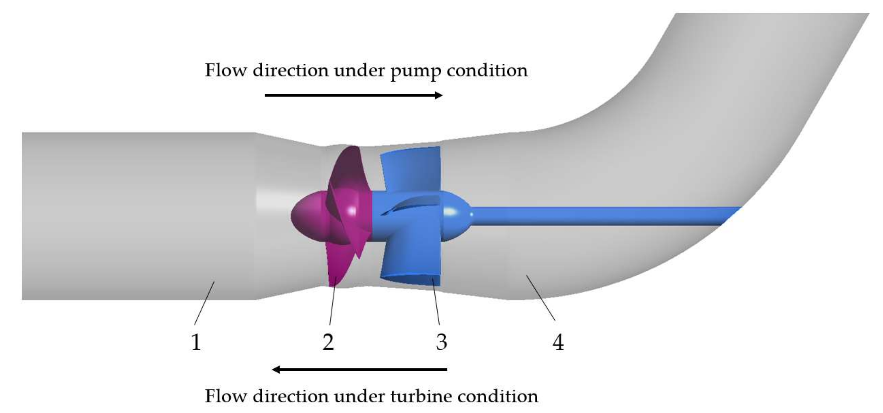
2.1. Three-Dimensional (3D) Modeling and Mesh Division

In this paper, an axial-flow pump model with a specific speed of 1000 was selected as the prototype of the research object. Its components include the inlet passage (straight pipe in pump operation and elbow in turbine operation), impeller, guide vane and outlet passage (elbow in pump operation and straight pipe in turbine operation), as shown in Figure 1. The main hydraulic parameters of the model are as follows: pump design flow rate is Q d e s = 0.39   m 3 / s ; turbine design flow rate is Q d e s = 0.47   m 3 / s ; rotational speed is n = 1450 r / min . The main structural parameters are as follows: the number of impeller blades is 3; the diameter of the impeller is 300 mm; the number of guide vane blades is 5; and the bending degree of the elbow is 60°. Four tip radial clearance schemes R were designed, namely, 0, 0.2, 1 and 2 mm, respectively.
In order to ensure the computational accuracy and convergence of the grid model, the computational domain was divided into structural grids [22,23,24]. ICEM was used to generate the grid of the inlet passage, impeller and outlet passage, and TuboGrid was used to generate the grid of the guide vane, as shown in Figure 2. Local mesh encryption was carried out on the wall surface around the blade and the rim clearance area to ensure that the wall Y+ value met the solution requirements of the turbulence model [25]. In order to ensure the accuracy of the calculation, a total of 15 layers of grids were divided at the blade tip clearance. The number of grid nodes of the inlet passage, guide vane and outlet passage was 1 million, 1.2 million and 1.4 million, respectively, and the number of grid nodes of the impeller under the four tip clearance schemes was controlled at approximately 1.8 million.

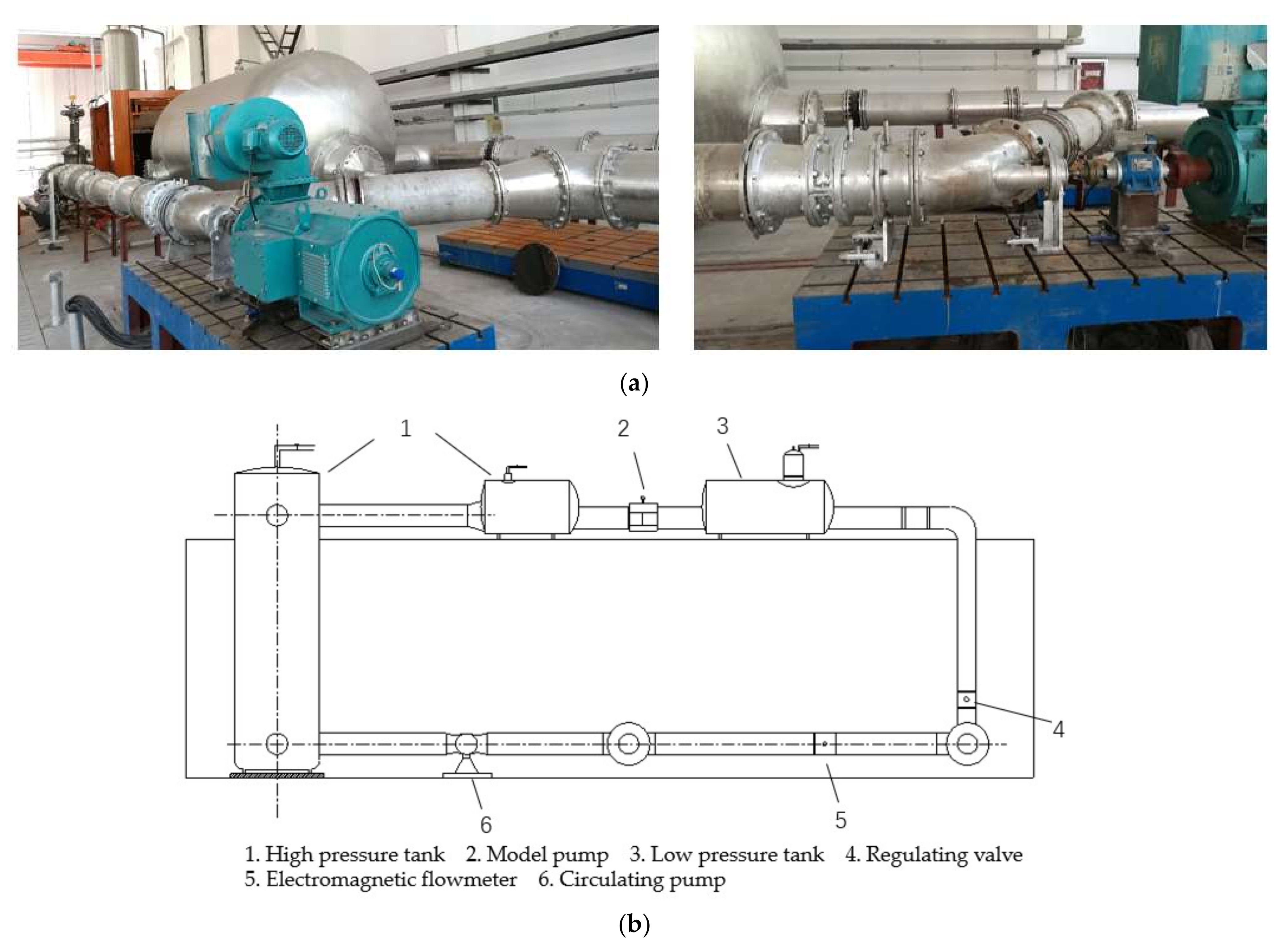
2.2. Setting of Boundary Conditions

Based on Newton’s continuity equation and momentum conservation equation for incompressible fluid, the SST k−ω [26,27] turbulence model was used to calculate the internal flow field and hydraulic performance of the axial-flow pump with different tip clearance schemes under axial-flow pump and turbine operating conditions. In both axial-flow pump and turbine operating conditions, the inlet passage adopts a mass flow rate condition, and the outlet passage adopts a static pressure condition [28]. The boundary details adopt a non-slip and smooth wall. The mixing model with stationary components is composed of “None”, and the mixing model with rotating and stationary interfaces is composed of a “Transient Rotor Stator”. The residual type of convergence criterion was RMS, which was set as 10−5, and the time step was 0.000344828 s, that is, the time required for the impeller to rotate 3°. The calculation cycle was set as 10 laps, and the total time was 0.413793 s.

2.3. Comparative Analysis of Calculation Results and Experiments

Figure 3 shows the test bench of axial-flow pump. In order to verify the feasibility of the model simulation, the external characteristics of the model pump simulation calculation were compared with the test results of the test bench of axial-flow pump. The flow rate was measured by a cologne intelligent electromagnetic flowmeter, the measurement uncertainty of which was ±0.2%; the head was measured by the YOKOGAWA EJA intelligent differential pressure transmitter, the measurement uncertainty of which was ±0.1%; torque speed was measured by the NJL2/500 Nm intelligent torque speed sensor, the measurement uncertainty of which was ±0.1%. Figure 4 shows the comparison between the experimental results and numerical calculation results of the model pump under different flow rates. The trend of CFD numerical calculation results is the same as that of the test results. The simulated operating efficiency of the axial-flow pump was slightly lower than the experimental value, and the error under the condition of a small flow rate was greater than that under the condition of a large flow rate, and the maximum relative error was 3.1%. The simulated head of the axial-flow pump was slightly lower than the test value under the condition of a small flow, and slightly higher than the test value under the condition of the design flow and large flow, and the maximum relative error was 2.1%. In conclusion, the error between the simulation results and the test results is small, and the reliability of the calculation results is good.

3. Entropy Production Analysis of Axial-Flow Pump with Different Tip Clearances under Pump and Turbine Conditions

3.1. Entropy Production Theory

According to the second law of thermodynamics, the fluid in the system is always accompanied by energy dissipation in the process of flow. Reynolds stress and the viscosity of the fluid itself will lead to irreversible energy dissipation in the flow process of the fluid inside the pump, while the eddy phenomenon generated in the flow will increase the energy dissipation, which will lead to an increase in entropy generation and hydraulic dissipation. The distribution of hydraulic loss in the axial-flow pump can be analyzed by entropy production theory.
Axial-flow pump internal entropy production ( Φ T ) ¯ is caused by direct entropy production S P R O , D ¯ and the turbulent entropy production S P R O , D ; the calculation formula is as follows:
( Φ T ) ¯ = S P R O , D ¯ + S P R O , D
S P R O , D ¯ = μ T ¯ · 2 v 1 ¯ x 2 + v 2 ¯ y 2 + v 3 ¯ z 2 + v 1 ¯ y + v 2 ¯ x 2 + v 1 ¯ z + v 3 ¯ x 2 + v 2 ¯ z + v 3 ¯ y 2
S PRO , D = μ T ¯ · 2 v 1 x 2 + v 2 y 2 + v 3 z 2 + v 1 y + v 2 x 2 + v 2 z + v 3 x 2 + v 2 z + v 3 y 2
Among them, v 1 ¯ ,   v 2 ¯ ,   v 3 ¯ are the components of the average time velocity on the coordinate x ,   y ,   z axes; v 1 ,   v 2 ,   v 3 are velocity pulsations on the x ,   y ,   z axes; μ is the dynamic viscosity; T ¯ is the time average temperature.
In order to solve the problem that S P R O , D in the formula cannot be calculated by solving the Reynolds equation, Kock [29,30] and Herwig [31,32] proposed Equation (4),
S P R O , D = ρ ε 1 T ¯
where ρ is the fluid density and ε 1 is the dissipation rate of turbulent kinetic energy.
The direct dissipation rate Φ D ¯ and turbulent dissipation rate Φ D , can be calculated from Equations (5) and (6):
Φ D ¯ = T ¯ · S P R O , D ¯
Φ D = T ¯ · S P R O , D
Thus, the direct dissipation and turbulent dissipation of each hydraulic component can be obtained by volume integration of Equations (5) and (6), as shown in Equations (7) and (8).
P D ¯ = V Φ D ¯ d V
P D = V Φ D d V
Therefore, the total dissipation rate Φ T and total dissipation P T can be calculated from Equations (9) and (10):
Φ T = Φ D ¯ + Φ D
P T = P D ¯ + P D

3.2. Analysis of Calculation Results

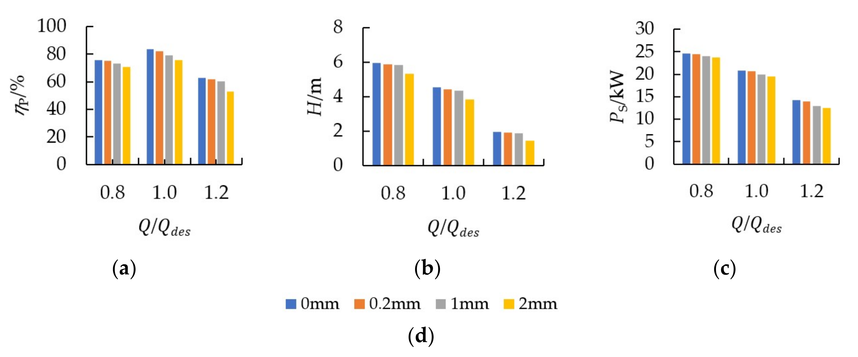
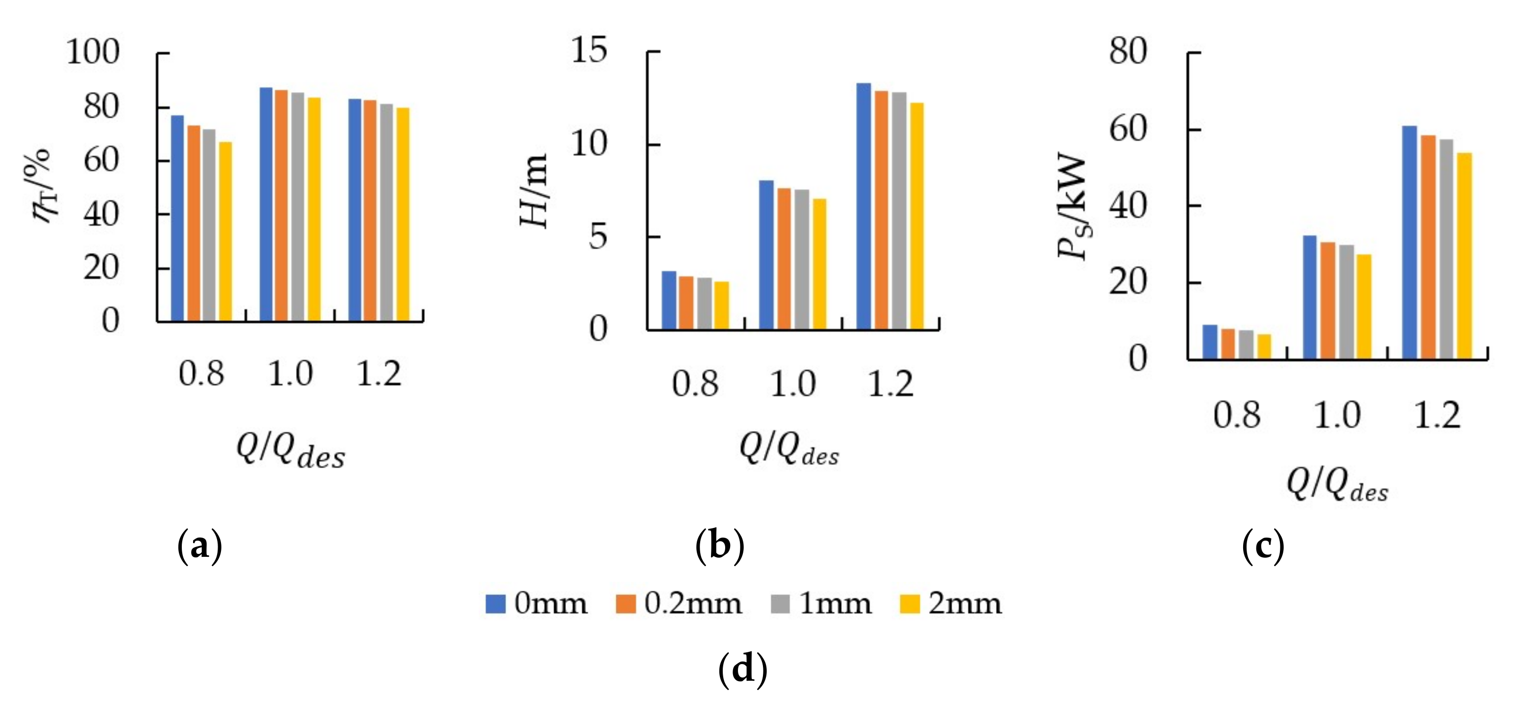
3.2.1. Influence of Tip Clearance on External Characteristics

Figure 5 shows the comparison of the influences of different tip clearances on the external characteristic parameters of the axial-flow pump operating under pump conditions. Under the pump condition, both the head and shaft power of the axial-flow pump decreased with the increase in the flow rate. Under the same flow condition, both the head and shaft power decreased with the increase in tip clearance. Under the conditions of 0.8 Q d e s , 1.0 Q d e s and 1.2 Q d e s , the head decreased by 10.0%, 15.5% and 25.7%. At 0.8 Q d e s , 1.0 Q d e s and 1.2 Q d e s , the shaft power decreased by 3.2%, 6.3% and 12.3%. When the flow rate increased from 0.8 Q d e s to 1.0 Q d e s , the efficiency increased; when the flow rate increased from 1.0 Q d e s to 1.2 Q d e s , the efficiency decreased.
Figure 6 shows the comparison of the influences of different tip clearances on the external characteristic parameters of the axial-flow pump under turbine conditions. Under the turbine condition, both the head and shaft power showed a rising trend with the increase in flow rate. Under the same flow condition, both the head and shaft power decreased with the increase in tip clearance. The decreases in the head were 18.5%, 12.0% and 7.9% under 0.8 Q d e s , 1.0 Q d e s and 1.2 Q d e s conditions. At 0.8 Q d e s , 1.0 Q d e s and 1.2 Q d e s , the shaft power decreased by 28.8%, 15.9% and 11.5%. When the flow rate increased from 0.8 Q d e s to 1.0 Q d e s , the efficiency increased; when the flow rate increased from 1.0 Q d e s to 1.2 Q d e s , the efficiency decreased. According to the formula:
H = P o u t P i n ρ g
where H —head, m ;   P o u t —the total pressure of outlet, Pa ;   P i n —the total pressure of inlet, Pa ; ρ —the fluid density, kg / m 3 ;   g —the acceleration of gravity, m / s 2 ;   P S —the shaft power, kW ;   η P —the efficiency of axial-flow pump; η T —the efficiency of axial-flow pump as a turbine; Q —the flow rate, kg / s ;   M —the torque of impeller, N · m ;   ω —the rotating speed, r / min .
It can be seen that the efficiency of the axial-flow pump was directly proportional to the head and inversely proportional to the shaft power, and the efficiency of axial-flow pump as a turbine was directly proportional to the shaft power and inversely proportional to the head. The efficiency of the axial-flow pump decreased greatly under the condition of a large flow rate, while the efficiency of the axial-flow pump as a turbine decreased slightly under the condition of a large flow rate. With the increase in tip clearance, the efficiency of the axial-flow pump showed a decreasing trend under both pump and turbine condition. In the pump condition, the maximum decrease was 7.1%, 9.8% and 15.3% under 0.8 Q d e s , 1.0 Q d e s and 1.2 Q d e s conditions, respectively. Under turbine conditions, the maximum decline was 12.7%, 4.5% and 3.9% under 0.8 Q d e s , 1.0 Q d e s and 1.2 Q d e s conditions, respectively.

3.2.2. Dissipation Distribution Based on Entropy Production Theory

Figure 7 shows the influence of tip clearance on total dissipation under the axial-flow pump condition. In all flow rate conditions, the total dissipation increased with the increase in tip clearance. With the increase in flow rate, the influence of tip clearance change on total dissipation decreased. Under the 0.8 Q d e s condition, the total dissipation increased by 47.7%; under the 1.0 Q d e s condition, the total dissipation increased by 45.0%; under the 1.2 Q d e s condition, the total dissipation increased by 11.2%.
Figure 8 shows the influence of tip clearance on total dissipation under the turbine condition of the axial-flow pump. Under all flow rate conditions, the total dissipation increased with the increase in tip clearance, and with the increase in flow rate, the influence caused by tip clearance changes also increased. Under the 0.8 Q d e s condition, the total dissipation increased by 7.9%; under the 1.0 Q d e s condition, the total dissipation increased by 10.5%; under the 1.2 Q d e s condition, the total dissipation increased by 14.9%.
Figure 9 shows the influence of tip clearance on the distribution of total dissipation inside the pump under different flow rate conditions. Tip clearance had an obvious influence on the impeller, guide vane and outlet passage, but had little influence on the inlet passage. Under all three flow conditions, the total dissipation of the impeller and outlet passage increased with the increase in tip clearance, and the influence of tip clearance was more obvious with the increase in flow rate. Under 0.8 Q d e s ,1.0 Q d e s and 1.2 Q d e s , the total dissipation of the impeller increased with the increase in tip clearance of 114.8%, 53.9% and 7.6%, respectively. The total dissipation of the outlet passage increased by 18.5%, 54.2% and 23.5% with the increase in tip clearance. For the guide vane, the total dissipation decreased with the increase in tip clearance at 0.8 Q d e s , with a maximum decrease of 8.4%. Under the condition of 1.0 Q d e s , the total dissipation increased with the increase in tip clearance, with a maximum increase of 32.1%. Under the condition of 1.2 Q d e s , the total dissipation of the guide vane decreased first and then increased with the increase in tip clearance.
Figure 10 shows the influence of tip clearance on the distribution of the internal dissipation of the pump turbine under different flow rate conditions. Tip clearance had an obvious influence on the impeller and outlet passage, but had little influence on the guide vane and inlet passage. Under the three flow rate conditions, the total dissipation in the impeller increased with the increase in tip clearance, and the smaller the flow rate was, the more obvious the influence of tip clearance was. The total dissipation increased by 4.9%, 22.7% and 42.2% with tip clearance at 0.8 Q d e s , 1.0 Q d e s and 1.2 Q d e s , respectively. For the outlet passage, the total dissipation increased with the increase in tip clearance at 0.8 Q d e s , and the maximum increase was 31.1%. However, under the conditions of 1.0 Q d e s and 1.2 Q d e s , the total dissipation decreased first and then increased with the increase in tip clearance.
Figure 11 shows the comparison of turbulence dissipation and direct dissipation caused by different tip clearance schemes in the pump and turbine conditions of the axial-flow pump under the design flow rate condition. As can be seen from the figure, the total dissipation generated by the direct loss of the axial-flow pump under pump and turbine conditions was very small compared with the turbulence loss. The maximum direct dissipation of the pump and turbine conditions was only 3.1% of the total dissipation, and the maximum direct dissipation of the turbine condition was only 2.8% of the total dissipation. Therefore, the dissipation inside the pump was mainly affected by turbulence dissipation.
Figure 12 shows the distribution of the blade surface dissipation rates with different tip clearances under the design flow rate of the pump condition. The dissipation rate from the hub to the rim on the blade surface increased gradually. A high dissipation area was generated at the rim on the pressure side. At the angle between the leading edge and the rim, a high dissipation area was formed on the suction side. On the suction side, the high dissipation area was significantly greater than the pressure side. This is due to the fact that the pressure side of the blade was mainly affected by the fluid circumferential velocity, and the suction side was mainly affected by fluid axial velocity; the fluid in the impeller had a great impact on the suction side of the blade. In addition, due to the increase in blade tip clearance, leakage and backflow phenomena at the clearance were intensified, leading to a gradual increase in the speed loss at the rim, and then the dissipation rate of the rim.
In order to more intuitively explain the influence of tip clearance on the axial-flow pump, the impeller and guide vanes were expanded radially on a cylindrical surface, as shown in Figure 13. The radial coefficient of the expanded surface r * can be calculated by Equation (12):
r * = ( r r h ) r t r h
where r is the radius of the cylinder, mm; r h is the radius of the hub, mm; r t is the radius of the rim, mm.
Figure 14 shows the cloud diagram of velocity distribution on the cylindrical section of the impeller under different tip clearance schemes and the pump design flow rate condition ( r * = 0.97 ). The flow velocity inside the impeller decreased from the impeller inlet to the impeller outlet, and as a result of the existence of the blade tip clearance, part of the fluid through the blade tip clearance produced return loss and leakage caused by impeller import flow velocity. The bigger the tip clearance, the greater the reflux and leakage phenomena; therefore, the increase in tip clearance speed reduced the impeller inlet from the front.
Figure 15 shows the distribution of the total dissipation rate on the cylindrical section of the impeller under different tip clearance schemes and the pump design flow rate condition ( r * = 0.97 ). The velocity loss caused by the backflow and leakage of some fluid in the impeller passing through the tip clearance led to an increase in the rate of dissipation; therefore, a high dissipation area was generated on the suction side of the impeller. With the increase in tip clearance, the dissipation rate on the suction side of the impeller increased gradually.
Figure 16 shows the cloud diagram of velocity distribution on the cylindrical section of the guide vane under different tip clearance schemes and the pump design flow rate condition ( r * = 0.99 ). The kinetic energy of the fluid was transformed into pressure energy after passing the guide vane; therefore, the flow velocity inside the guide vane decreased from the inlet to the outlet; there was a large amount of backflow at the outlet of the guide vane, which led to a low-speed zone here, and a point with the lowest speed was formed at the guide vane inlet due to the mixture of backflow and mainstream. The impeller clearance also caused speed loss, resulting in a gradual decrease in the internal flow velocity of the guide vane with the increase in tip clearance.
Figure 17 shows the distribution of the total dissipation rate on the cylindrical section of the guide vane under different tip clearance schemes and the pump design flow rate condition ( r * = 0.99 ). The high dissipation area inside the guide vane was the suction side and the inlet of the guide vane, where the velocity gradient was large, leading to the generation of high dissipation. The high dissipation area at the suction side was caused by the impact of backflow; the velocity gradient near the inlet of guide vane was large, which also resulted in high entropy production.
Figure 18 shows the internal dissipation rate distribution of the inlet passage with different tip clearances under the pump design flow rate condition. Energy dissipation in the inlet passage mainly occurred at the inlet, the bend of the inner wall of the elbow and the junction of the rotating shaft and the outer wall. As the fluid in the inlet passed through the inlet transition section, the bend of the passage wall and the rotation around the rotating shaft, a certain degree of flow separation occurred, which resulted in energy dissipation.
Figure 19 shows the distribution of blade surface dissipation rates with different tip clearances under the design flow rate of the turbine condition. The surface dissipation rate of the blade pressure side increased gradually from the hub to the rim and produced a higher dissipation at the rim. The suction side produced a high dissipation area at the angle between the rim and the leading edge; the area of the high dissipation rate on the suction side was obviously larger than that on the pressure side. This shows that when the impeller runs under the turbine condition, the fluid cannot pass through the suction side properly, which has a great impact on it. In addition, with the increase in blade tip clearance, the leakage and backflow in the clearance were intensified, and as a result, the speed loss at the rim increased gradually, and then the dissipation rate of the rim increased gradually.
Figure 20 shows the cloud diagram of velocity distribution on the cylindrical section of the impeller under different tip clearance schemes and the turbine design flow rate condition ( r * = 0.97 ). The flow velocity on the suction side of the impeller was obviously greater than that on the pressure side; under the turbine condition, the fluid could not flow well over the suction side surface, and obvious flow separation occurred at the leading and trailing edges of the impeller; therefore, a low-speed zone was generated at the leading and trailing edges of the impeller.
Figure 21 shows the distribution of the total dissipation rate on the cylindrical section of the impeller under different tip clearance schemes and the turbine design flow rate condition ( r * = 0.97 ). As the fluid near the blade suction side could not fit the blade surface effectively. This had a great impact and flow separation phenomenon and caused a large velocity gradient on the blade suction side. There was a high dissipation area on the suction side of the impeller. High energy dissipation also occurred at the blade outlet due to flow separation. With the increase in tip clearance, the dissipation rate of impeller working surface and outlet increased gradually.
Figure 22 shows the distribution of the dissipation rate of the outlet passage with different tip clearances under the turbine design flow rate condition. There was no rear guide vane when the axial-flow pump operated as a turbine. The fluid at the outlet of the impeller lacked the rectifier action of the guide vane. There was a high dissipation area at the inlet of the outlet passage. With the increase in tip clearance, the dissipation rate at the inlet of outlet passage increased. Moreover, due to the effect of the passage wall, the kinetic energy flowing out of the impeller was converted into pressure energy; therefore, the dissipation rate of the outlet passage decreased from the inlet to the outlet.

4. Conclusions

In this paper, a numerical simulation method was adopted to study the energy loss of the axial-flow pump under both pump and turbine conditions based on entropy production theory, and four different tip clearance schemes were analyzed. The following conclusions can be drawn:
  • The efficiency, head and shaft power of the axial-flow pump under pump and turbine conditions all showed a downward trend with the increase in tip clearance. The maximum decline occurred at the 1.2 Q d e s flow rate under pump condition and the 0.8 Q d e s flow rate under turbine condition. Compared with the 0 mm clearance, the maximum decreases in pump efficiency, head and shaft power under 2 mm tip clearance were 15.3%, 25.7% and 12.3%, respectively, under the pump condition, and 12.7%, 18.5% and 28.8% under the turbine condition.
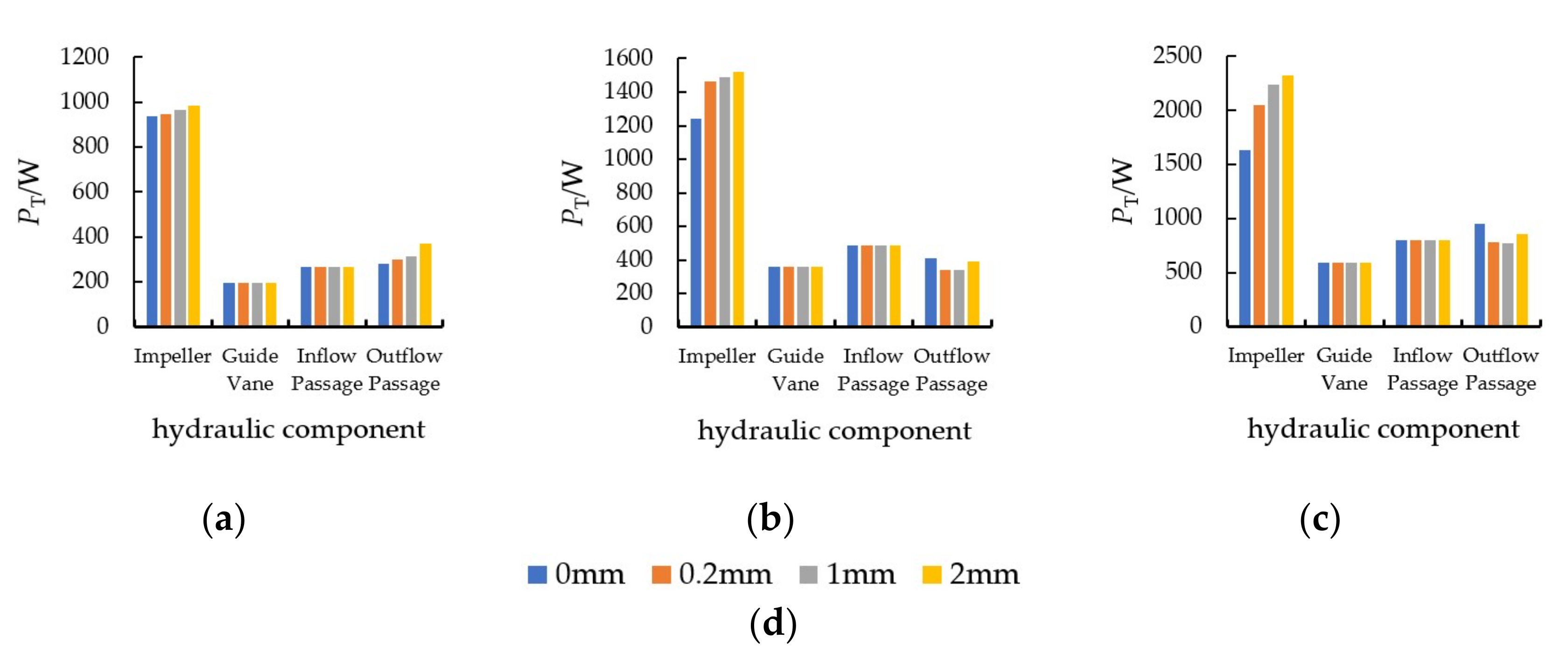
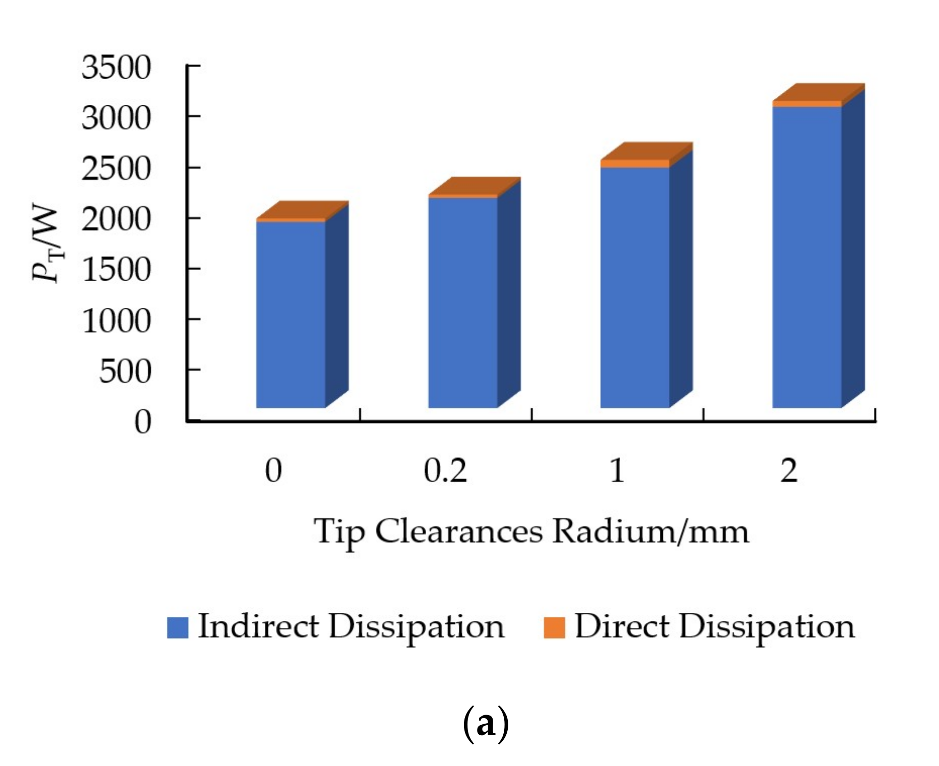
  • Under the pump condition of the axial-flow pump, the change in tip clearance had an obvious effect on the total dissipation of the impeller, guide vane and outlet passage. Under the flow rate of 1.0 Q d e s , the maximum variation in the total dissipation of the impeller, guide vane and outlet passage was 53.9%, 32.1% and 54.2%, respectively. Under the turbine condition of the axial-flow pump, the change in tip clearance had an obvious effect on the total dissipation of the impeller and outlet passage. Under the flow rate of 1.0 Q d e s , the maximum variation in the total dissipation of the impeller and outlet passage was 22.7% and 17.4%, respectively. The total dissipation of the axial-flow pump increased with the increase in tip clearance under both pump and turbine conditions, in addition, under the flow rate of 1.0 Q d e s , the change in the total dissipation under the pump condition with the increase in tip clearance was significantly greater than that under the turbine condition, and the total dissipation was 45.0% and 10.5%, respectively.
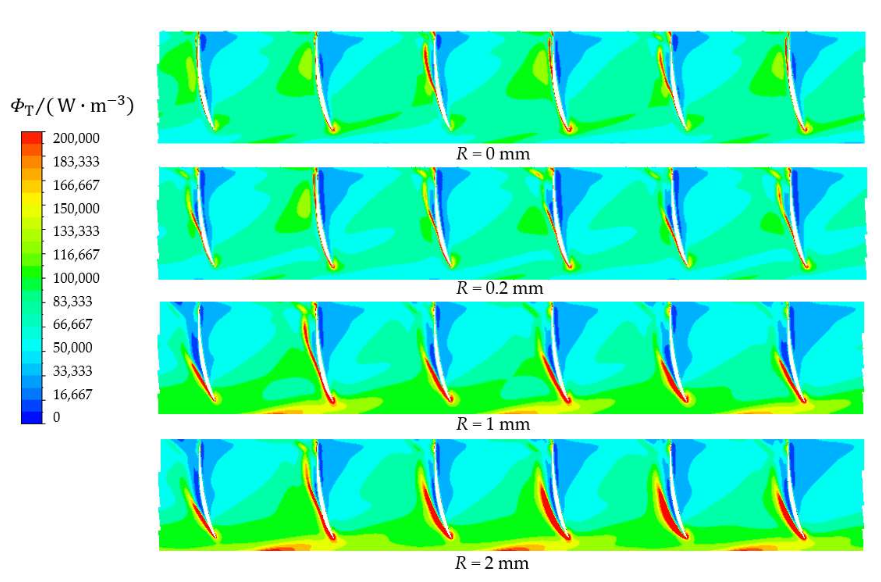
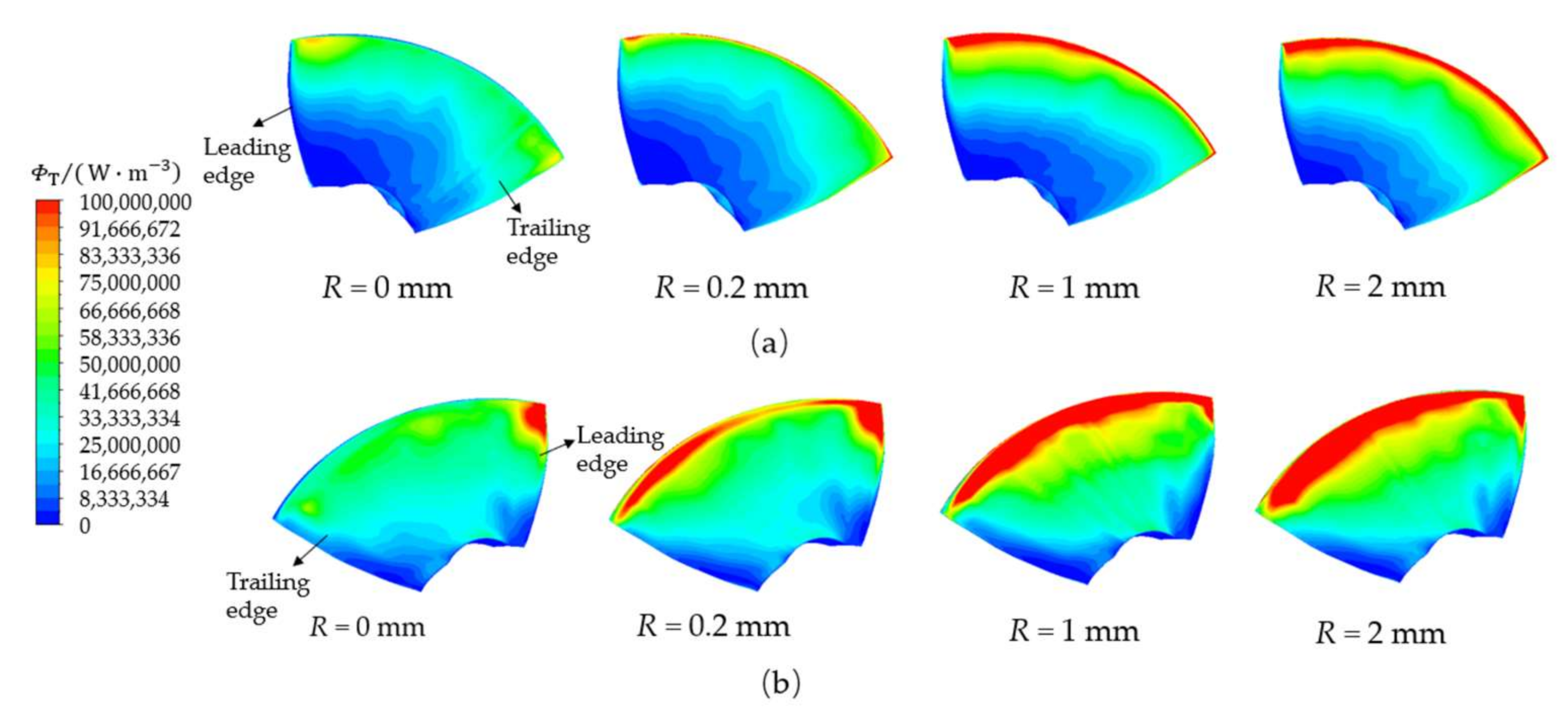
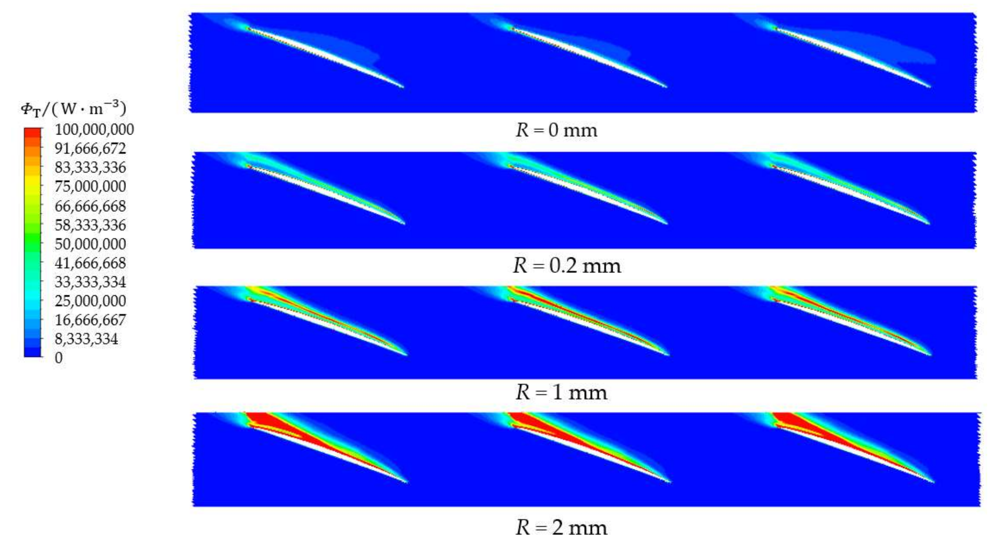
  • At the design flow rate, when the axial-flow pump ran under both pump and turbine conditions, the dissipation rate of the pressure side was lower than that of the suction side. When the axial-flow pump operated under the pump condition, there was a high dissipation area at the rim of the impeller, the impeller inlet. When the axial-flow pump operated under the turbine condition, at the rim impeller, the impeller outlet produced a high dissipation area. With the increase in tip clearance, total dissipation in the impeller increased gradually.
Therefore, a smaller tip clearance should be selected when the pump condition is the main condition; however, a larger tip clearance can be selected when the turbine condition is the main condition. The study result shows the relationship between blade tip clearance and dissipation loss in the pump and its spatial distribution under both pump and turbine conditions. This provides suggestions for the optimization of the axial-flow pump as a turbine, to find suitable tip clearance in the axial-flow pump as a turbine, and provides a reference for solving the problems of large vibration and noise, low operating efficiency caused by clearance that is too large, and manufacturing difficulty caused by clearance that is too small.

Author Contributions

Conceptualization, Y.L. and Q.L.; methodology, Y.L. and F.M.; software, Q.L.; validation, Y.L. and Q.L.; formal analysis, Q.L.; investigation, Q.L.; resources, Q.L.; data curation, Y.L. and Q.L.; writing—original draft preparation, Q.L.; writing—review and editing, Q.L. and F.M.; visualization, Q.L.; supervision, Y.Z. and X.X.; project administration, Y.L.; funding acquisition, Y.L. All authors have read and agreed to the published version of the manuscript.

Funding

This research was funded by National Natural Science Foundation of China, grant number 51809120 and Industry-University-Research Collaboration of Jiangsu Province, grant number BY2020373.

Institutional Review Board Statement

Not applicable.

Informed Consent Statement

Not applicable.

Data Availability Statement

Not applicable.

Conflicts of Interest

The authors declare no conflict of interest.

Nomenclature

Q des   m 3 / s design flow rate under pump condition
Q des   m 3 / s design flow rate under turbine condition
n   r / min rotational speed
R   mm tip clearance radius
S PRO , D ¯ W · K / m 3 direct dissipation
S PRO ,   D   W · K / m 3 turbulent dissipation
v 1 ¯ , v 2 ¯ , v 3 ¯   m / s time average velocity on the coordinate x ,   y ,   z axes
v 1 , v 2 , v 3 m / s velocity pulsations on the x ,   y ,   z axes
μ Pa · s dynamic viscosity
T ¯ K time average temperature
ρ   kg / m 3 fluid density
ε 1   W / kg dissipation rate of turbulent kinetic energy
Φ D ¯   W / m 3 direct dissipation rate
Φ D W / m 3 turbulent dissipation rate
P D ¯   W direct dissipation
P D   W turbulent dissipation
Φ T   W / m 3 total dissipation rate
P T   W total dissipation
H m head
P out Pa total pressure of outlet
P in Pa total pressure of inlet
ρ kg / m 3 fluid density
g m / s 2 acceleration of gravity
P S kW shaft power
η P % efficiency of axial-flow pump
η T % efficiency of axial-flow pump as a turbine
Q kg / s flow rate
M N · m torque of impeller
ω r / min rotating speed
r mm radius of the cylinder
r h mm radius of the hub
r t mm radius of the rim

References

  1. Wang, W.; Wang, W.; Zhang, L.; Zhao, L.; Lu, J.; Feng, J.; Luo, X. Mechanism for end-wall slots to improve hump in an axial flow pump. Trans. Chin. Soc. Agric. Eng. 2020, 36, 12–20. (In Chinese) [Google Scholar]
  2. Wang, X.H.; Yang, J.H.; Shi, F.X. Status and prospect of study on energy recovery hydraulic turbines. J. Drain. Irrig. Mach. Eng. 2014, 32, 742–747. [Google Scholar]
  3. Yang, S.S.; Derakhshan, S.; Kong, F.Y. Theoretical, numerical and experimental prediction of pump as turbine performance. Renew. Energy 2012, 48, 507–513. [Google Scholar] [CrossRef]
  4. Yang, S.S.; Kong, F.Y.; Jiang, W.M.; Qu, X.Y. Effects of impeller trimming influencing pump as turbine. Comput. Fluids 2012, 67, 72–78. [Google Scholar] [CrossRef]
  5. Yang, S.S.; Liu, H.L.; Kong, F.Y.; Xia, B.; Tan, L.W. Effects of the radial gap between impeller tips and volute tongue influencing the performance and pressure pulsations of pump as turbine. J. Fluids Eng. 2014, 136, 054501. [Google Scholar] [CrossRef]
  6. Singh, P.; Nestmann, F. An optimization routine on a prediction and selection model for the turbine operation of centrifugal pumps. Exp. Therm. Fluid Sci. 2010, 34, 152–164. [Google Scholar] [CrossRef]
  7. Singh, P.; Nestmann, F. Internal hydraulic analysis of impeller rounding in centrifugal pumps as turbines. Exp. Therm. Fluid Sci. 2011, 35, 121–134. [Google Scholar] [CrossRef]
  8. Joshi, S.; Gordon, A.; Holloway, L.; Chang, L. Selecting a high specific speed pump for low head hydro-electric power generation. In Proceedings of the Canadian Conference on Electrical and Computer Engineering, Saskatoon, SK, Canada, 1–4 May 2005; pp. 603–606. [Google Scholar]
  9. Qian, Z.; Wang, F.; Guo, Z.; Lu, J. Performance evaluation of an axial-flow pump with adjustable guide vanes in turbine mode. Renew. Energy 2016, 99, 1146–1152. [Google Scholar] [CrossRef]
  10. Li, D.; Wang, H.; Qin, Y.; Han, L.; Wei, X.; Qin, D. Entropy production analysis of hysteresis characteristic of a pump-turbine model. Energy Convers. Manag. 2017, 149, 175–191. [Google Scholar] [CrossRef]
  11. Zhang, Y.X.; Hou, H.C.; Xu, C.; He, W.; Li, Z. Application of entropy production method to centrifugal pump energy loss evaluation. J. Drain. Irrig. Mach. Eng. 2017, 288, 277–282. [Google Scholar]
  12. Pei, J.; Meng, F.; Li, Y.; Yuan, S.; Chen, J. Effects of distance between impeller and guide vane on losses in a low head pump by entropy production analysis. Adv. Mech. Eng. 2016, 8, 1687814016679568. [Google Scholar] [CrossRef] [Green Version]
  13. Li, D.; Gong, R.; Wang, H.; Xiang, G.; Wei, X.; Qin, D. Entropy Production Analysis for Hump Characteristics of a Pump Turbine Model. Chin. J. Mech. Eng. 2016, 29, 803–812. [Google Scholar] [CrossRef]
  14. Gong, R.; Wang, H.; Chen, L.; Li, D.; Zhang, H.; Wei, X. Application of entropy production theory to hydro-turbine hydraulic analysis. Sci. China Technol. Sci. 2013, 56, 1636–1643. [Google Scholar] [CrossRef]
  15. Shi, W.; Li, T.; Zhang, D.; Wang, G.; Zhou, L. Numerical simulation on cavitating characteristic in impeller of axial-flow pump. Trans. CSAE 2012, 28, 88–93. (In Chinese) [Google Scholar]
  16. Li, W.; Qiao, W.; Xu, K.; Luo, H. Numerical simulation of active control on tip leakage flow in axial turbine. Chin. J. Aeronaut. 2009, 22, 129–137. [Google Scholar] [CrossRef] [Green Version]
  17. Shi, W.D.; Li, T.T.; Zhang, D.S.; Tian, F.; Zhang, G.J. Numerical Simulation of Tip Clearance Leakage Vortex Flow Characteristic in Axial Flow Pump; Institute of Physics Publishing: Bristol, UK, 2012. [Google Scholar]
  18. Shen, S.; Qian, Z.; Ji, B.; Agarwal, R.K. Numerical investigation of tip flow dynamics and main flow characteristics with varying tip clearance widths for an axial-flow pump. Proc. Inst. Mech. Eng. Part. A J. Power Energy 2018, 233, 476–488. [Google Scholar] [CrossRef]
  19. Chen, G.T.; Greitzer, E.M.; Tan, C.S.; Marble, F.E. Similarity Analysis of Compressor Tip Clearance Flow Structure. J. Turbomach. 1991, 113, 260–271. [Google Scholar] [CrossRef]
  20. Li, W.; Qiao, W.Y.; Xu, K.F.; Luo, H.L. Numerical simulation of tip clearance flow passive control in axial turbine. J. Therm. Sci. 2008, 17, 147–155. [Google Scholar] [CrossRef]
  21. Han, W.; Liu, Y.; Gong, C.; Su, Y.; Guo, P.; Su, M.; Wei, Z. Effect of tip clearance on performance of contra-rotating axial flow water-jet propulsion pump. Mod. Phys. Lett. B 2020, 34, 2050094. [Google Scholar] [CrossRef]
  22. Shi, L.; Zhu, J.; Tang, F.; Wang, C. Multi-Disciplinary optimization design of axial-flow pump impellers based on the approximation model. Energies 2020, 13, 779. [Google Scholar] [CrossRef] [Green Version]
  23. Wang, H.; Long, B.; Wang, C.; Han, C.; Li, L. Effects of the impeller blade with a slot structure on the centrifugal pump performance. Energies 2020, 13, 1628. [Google Scholar] [CrossRef]
  24. Zhang, L.; Wang, C.; Zhang, Y.; Xiang, W.; He, Z.; Shi, W. Numerical study of coupled flow in blocking pulsed jet impinging on a rotating wall. J. Braz. Soc. Mech. Sci. Eng. 2021, 43, 508. [Google Scholar] [CrossRef]
  25. Fujun, W. Computational Fluid Dynamics Analysis—CFD Principles and Application; Tsinghua University Press: Beijing, China, 2004. [Google Scholar]
  26. Yang, Y.; Zhou, L.; Zhou, H.; Lv, W.; Wang, J.; Shi, W.; He, Z. Orthogonal optimum design method for high specific-speed axial-flow pumps. J. Vib. Shock. 2018, 37, 115–121. (In Chinese) [Google Scholar]
  27. Feng, J.; Luo, X.; Guo, P.; Wu, G. Influence of tip clearance on pressure fluctuations in an axial flow pump. J. Mech. Sci. Technol. 2016, 30, 1603–1610. [Google Scholar] [CrossRef]
  28. Yang, S.; Kong, F.; Chen, B. Research on Pump Volute Design Method Using CFD. Int. J. Rotating Mach. 2011, 2011, 137860. [Google Scholar] [CrossRef]
  29. Kock, F.; Herwig, H. Entropy production calculation for turbulent shear flows and their implementation in cfd codes. Int. J. Heat Fluid Flow 2005, 26, 672–680. [Google Scholar] [CrossRef]
  30. Kock, F.; Herwig, H. Local entropy production in turbulent shear flows: A high-Reynolds number model with wall functions. Int. J. Heat Mass Transf. 2004, 47, 2205–2215. [Google Scholar] [CrossRef]
  31. Herwig, H.; Kock, F. Direct and indirect methods of calculating entropy generation rates in turbulent convective heat transfer problems. Heat Mass Transf. 2007, 43, 207–215. [Google Scholar] [CrossRef]
  32. Herwig, H.; Kock, F. Local entropy production in turbulent shear flows: A tool for evaluating heat transfer performance. J. Therm. Sci. 2006, 15, 159–167. [Google Scholar] [CrossRef]
Figure 1. Three-dimensional model of axial-flow pump. 1—inlet passage; 2—impeller; 3—guide vane; 4—outlet passage.
Machines 10 00056 g001
Figure 2. Axial-flow pump and impeller grid.
Machines 10 00056 g002
Figure 3. Test bench of axial-flow pump. (a) Test instruments. (b) Layout of test bench.
Machines 10 00056 g003
Figure 4. Comparison of model pump external characteristics test and numerical calculation results.
Machines 10 00056 g004
Figure 5. Comparison of (a) efficiency; (b) head; (c) shaft power under different tip clearances in pump condition; (d) Legend.
Machines 10 00056 g005
Figure 6. Comparison of (a) efficiency; (b) head; (c) shaft power under different tip clearances in turbine condition; (d) Legend.
Machines 10 00056 g006
Figure 7. Influence of tip clearance on total dissipation under pump condition.
Machines 10 00056 g007
Figure 8. Influence of tip clearance on total dissipation under turbine condition.
Machines 10 00056 g008
Figure 9. Influence of tip clearance on total dissipation under pump condition; (a) 0.8 Q d e s ; (b) 1.0 Q d e s ; (c)1.2 Q d e s ; (d) Legend.
Machines 10 00056 g009
Figure 10. Influence of tip clearance on total dissipation under turbine condition; (a) 0.8 Q d e s ; (b) 1.0 Q d e s ; (c) 1.2 Q d e s ; (d) Legend.
Machines 10 00056 g010
Figure 11. Comparison of direct dissipation and turbulence dissipation; (a) Pump condition; (b) Turbine condition.
Machines 10 00056 g011aMachines 10 00056 g011b
Figure 12. Dissipation rate distribution on blade surface under pump condition. (a) Pressure side. (b) Suction side.
Machines 10 00056 g012
Figure 13. Cylinder section of impeller and guide vane.
Machines 10 00056 g013
Figure 14. Cylindrical distribution of impeller internal velocity under pump condition ( r * = 0.97 ).
Machines 10 00056 g014
Figure 15. Cylinder distribution of internal dissipation rate of impeller under pump condition ( r * = 0.97 ).
Machines 10 00056 g015
Figure 16. Cylindrical distribution of guide vane internal velocity under pump conditions ( r * = 0.99 ).
Machines 10 00056 g016
Figure 17. Cylinder distribution of internal dissipation rate of guide vane under pump condition ( r * = 0.99 ).
Machines 10 00056 g017
Figure 18. Distribution of internal dissipation rate in outflow passage under pump condition.
Machines 10 00056 g018
Figure 19. Dissipation rate distribution on blade surface under turbine condition. (a) Pressure side. (b) Suction side.
Machines 10 00056 g019
Figure 20. Cylindrical distribution of impeller internal velocity under turbine condition ( r * = 0.97 ).
Machines 10 00056 g020
Figure 21. Cylinder distribution of internal dissipation rate of impeller under turbine condition ( r * = 0.97 ).
Machines 10 00056 g021
Figure 22. Distribution of internal dissipation rate in outflow passage under turbine condition.
Machines 10 00056 g022
Publisher’s Note: MDPI stays neutral with regard to jurisdictional claims in published maps and institutional affiliations.

