
Potential for Volcanogenic Massive Sulfide Mineralization at the A6 Anomaly, North-West British Columbia, Canada: Stratigraphy, Lithogeochemistry, and Alteration Mineralogy and Chemistry

Abstract
:1. Introduction
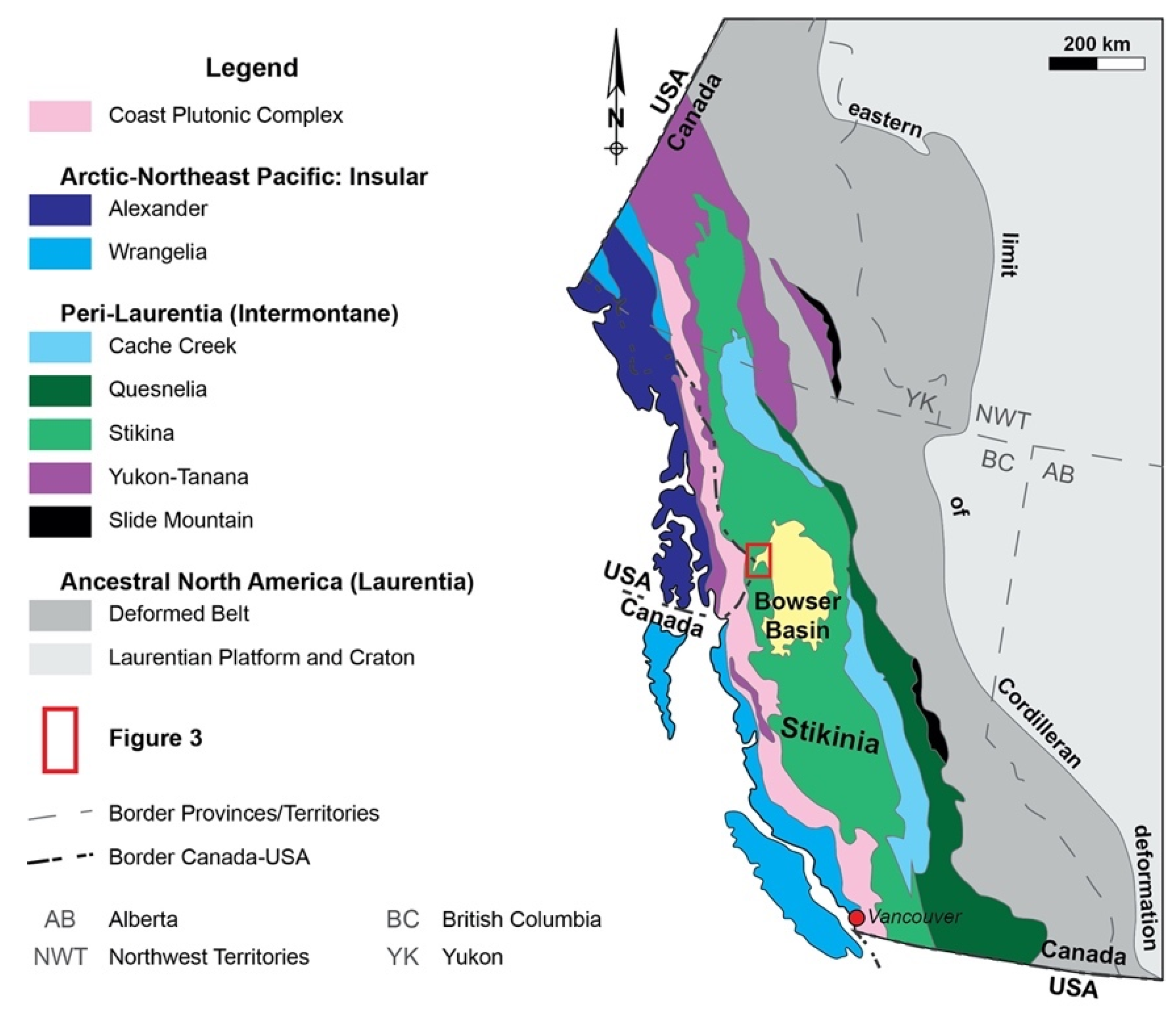
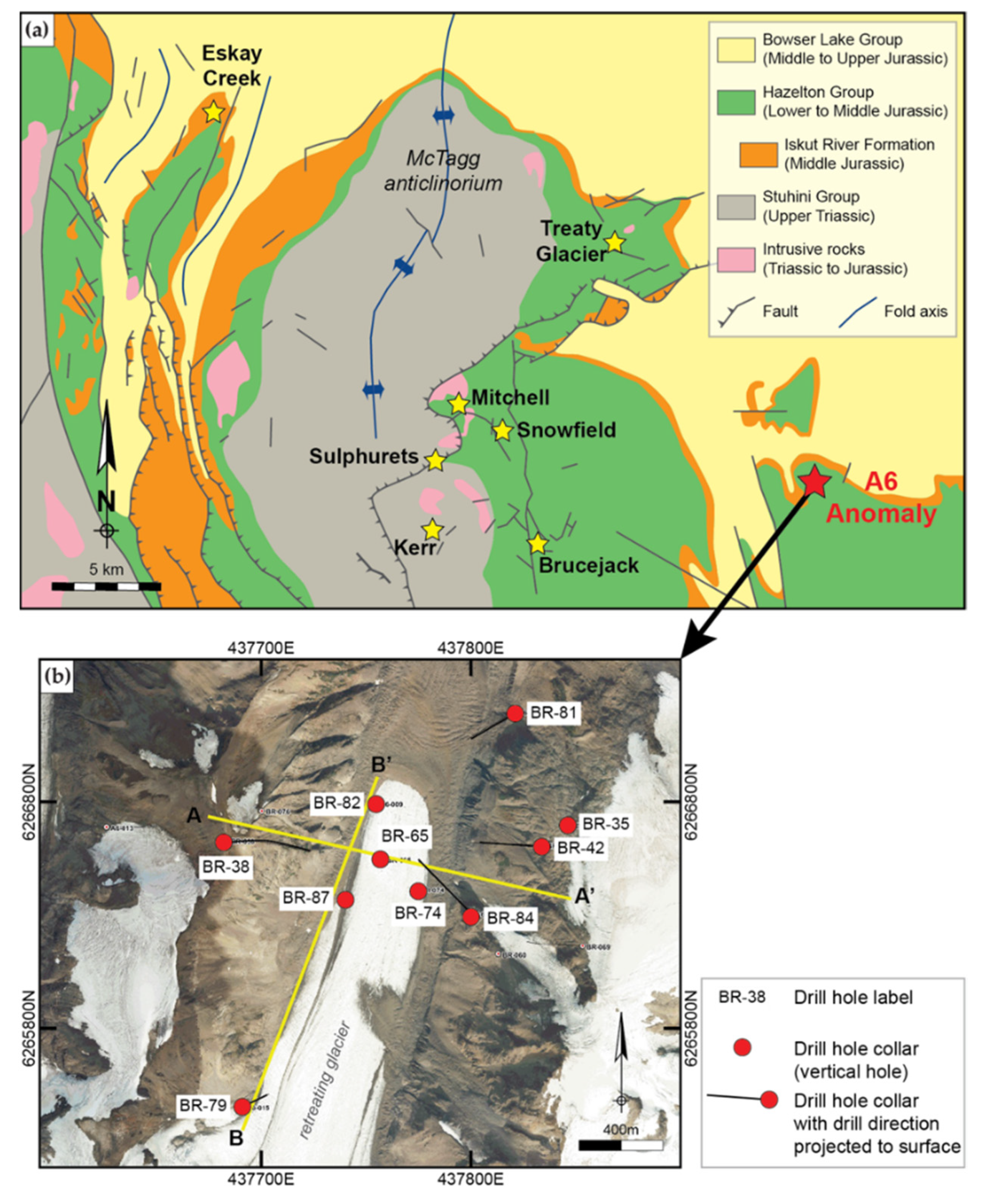
2. Geological Setting
2.1. Regional Geological Setting

| Deposit/Prospect | Age [Ma] | Lithology | Reference |
|---|---|---|---|
| KSM | 193.9 ± 0.5 to 190.3 ± 0.8 | Altered and mineralized diorite | [7,34,42] |
| Snowfield | 189.6 ± 2.2 | Porphyry | [43] |
| Brucejack | ≤184 | Porphyritic lava flow | [1,44] |
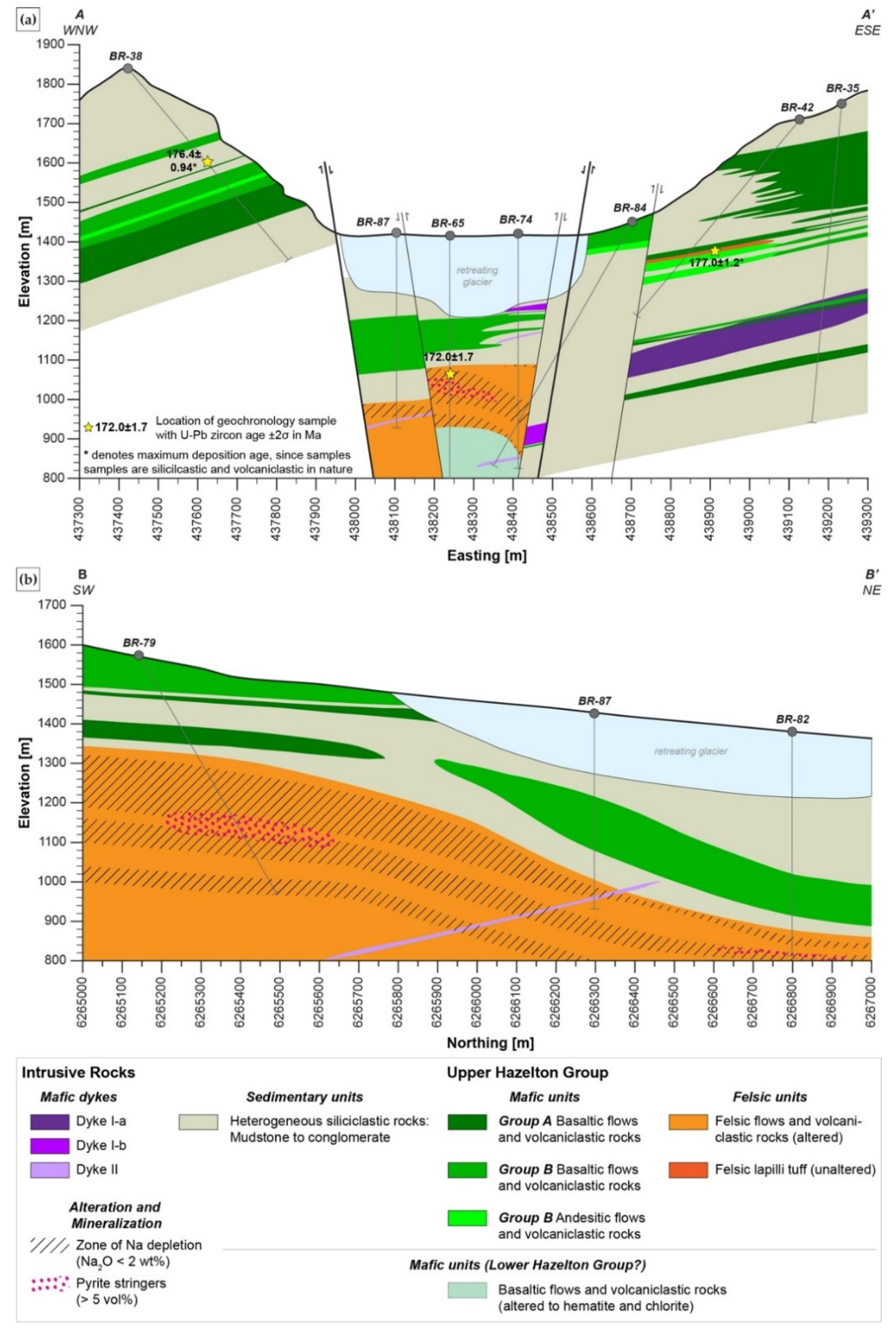
| A6 Anomaly | 172.0 ± 1.7 | Felsic volcanic and volcaniclastic rocks (BR-65) | [45] |
| 176.4 ± 0.94 * | Heterolithic sandstone (BR-38) | ||
| 177.0 ± 1.2 * | Intermediate volcaniclastic rock (E flank from BR-69) | ||
| Eskay Creek | 175.0 ± 2.0 | Eskay Rhyolite Member | [2] |
2.2. Stratigraphy of the A6 Anomaly
3. Materials and Methods
3.1. Whole Rock Lithogeochemistry
3.2. SEM
3.3. XRD
3.4. EMPA
3.5. SIMS
4. Results
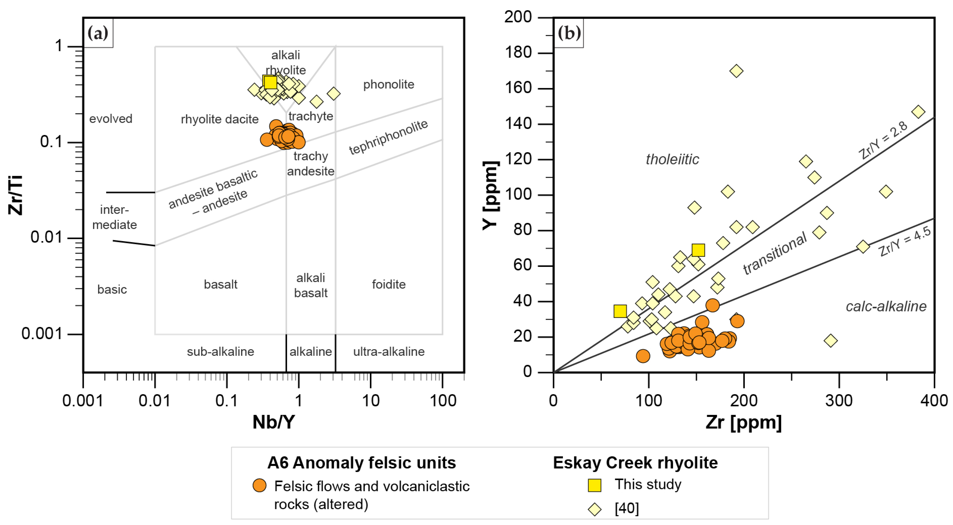
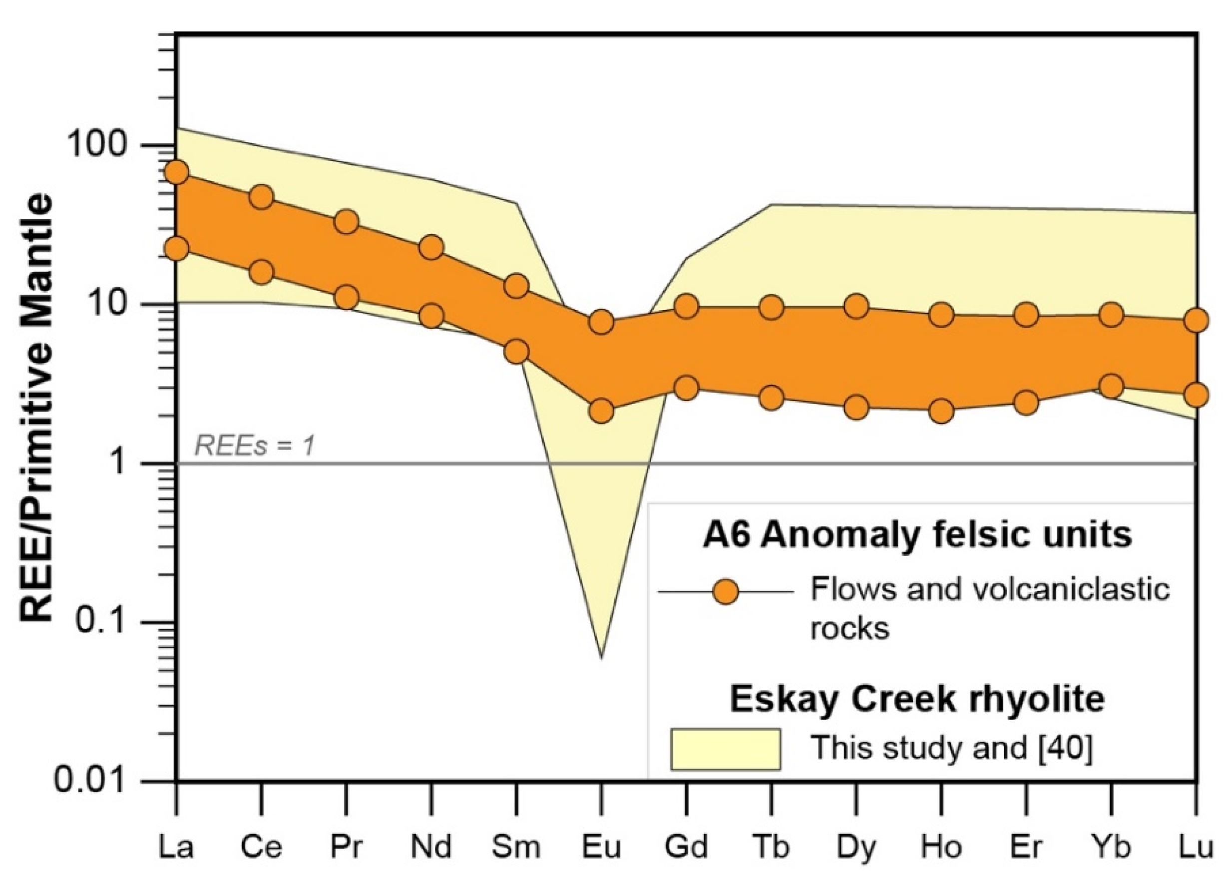
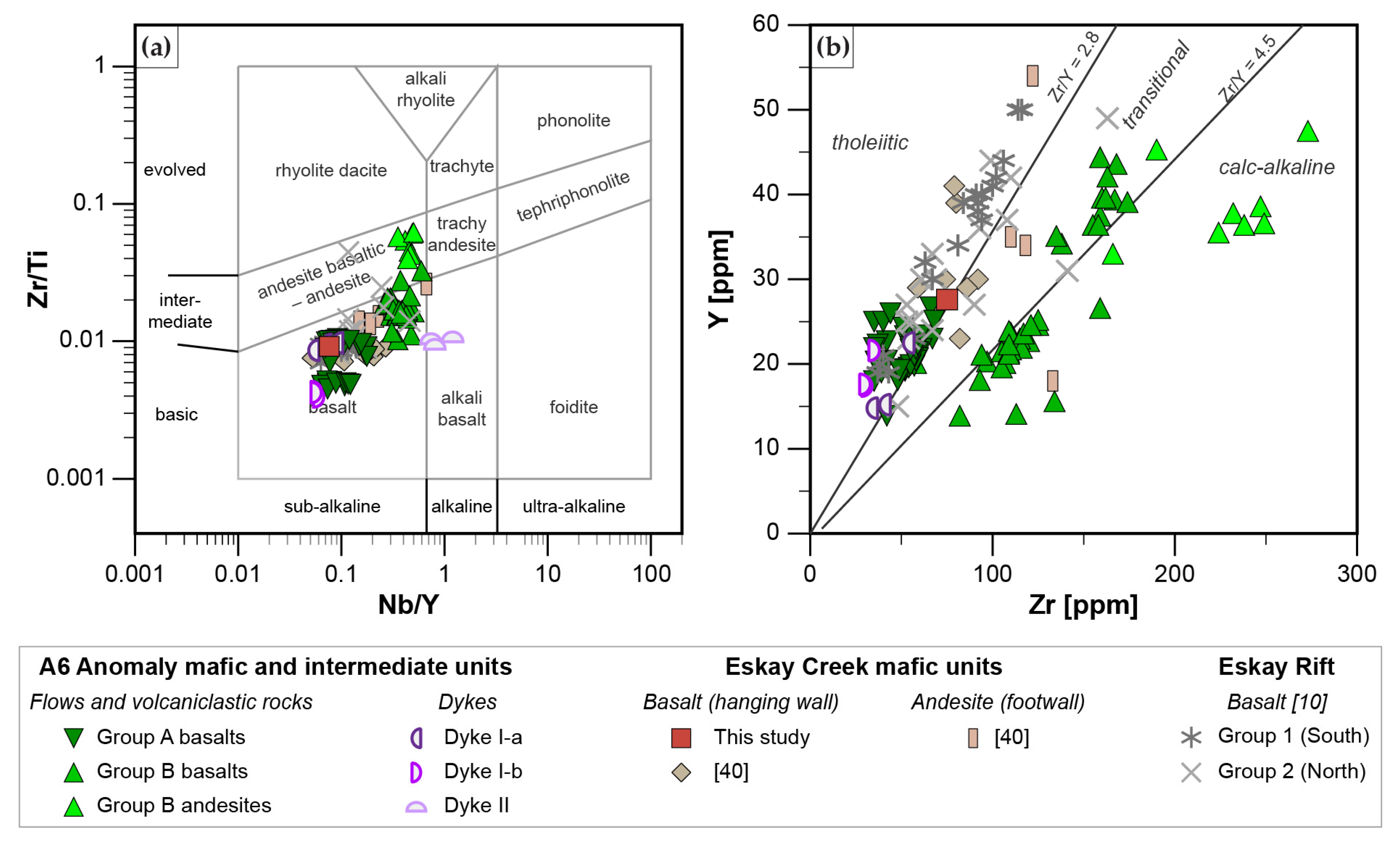
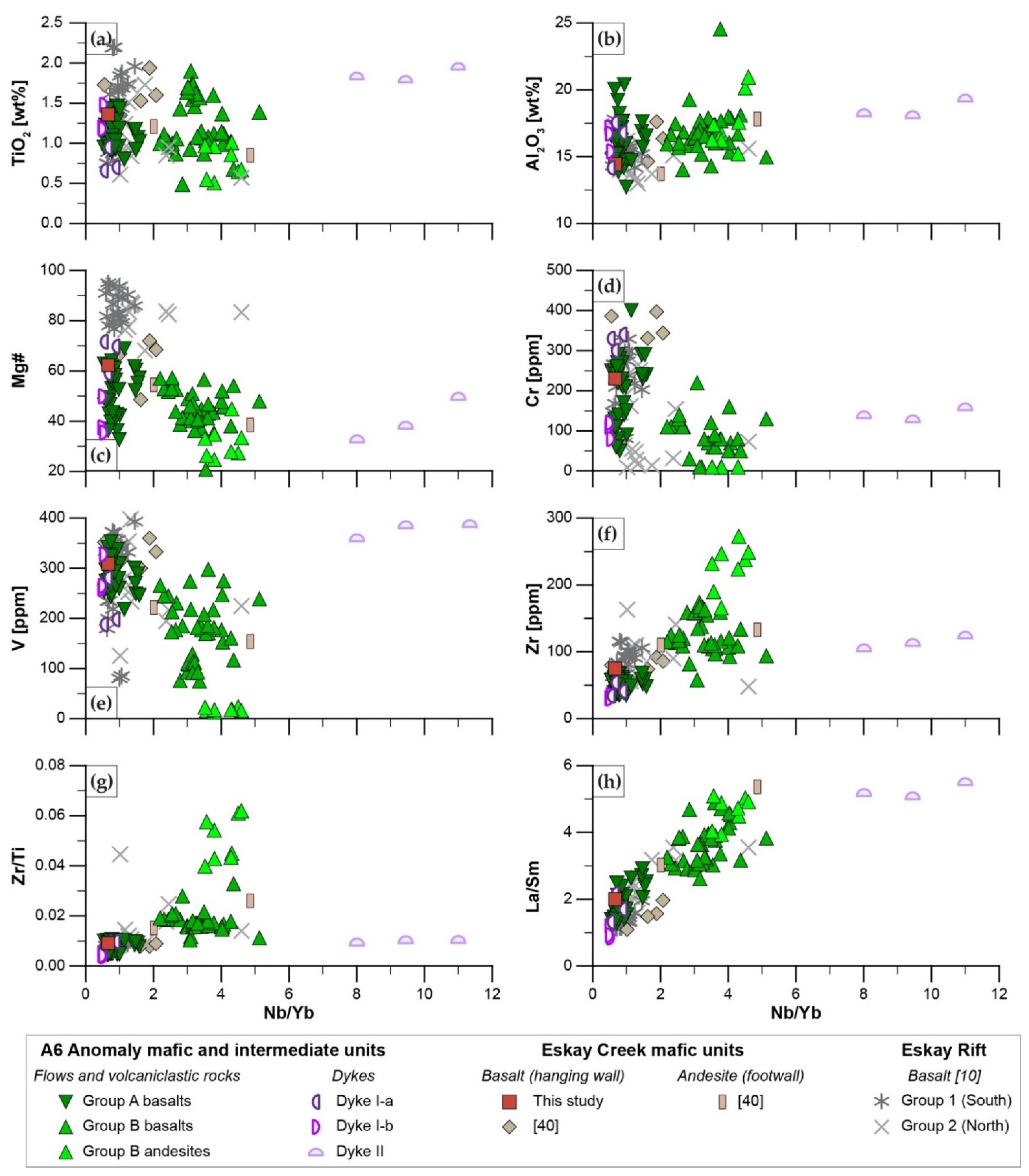
4.1. Whole Rock Lithogeochemistry
| Felsic Units | Group A Basalts | Group B Basalts | Group B Andesites | Dyke I-a | Dyke I-b | Dyke II | |
|---|---|---|---|---|---|---|---|
| Av ± Stdev | Av ± Stdev | Av ± Stdev | Av ± Stdev | Av ± Stdev | Av ± Stdev | Av ± Stdev | |
| n | 43 | 38 | 38 | 8 | 3 | 3 | 3 |
| SiO2 [wt%] | 69.9 ± 3.93 | 42.1 ± 4.14 | 49.2 ± 4.43 | 60.7 ± 4.56 | 40.9 ± 3.04 | 41.4 ± 3.84 | 39.0 ± 4.98 |
| TiO2 | 0.21 ± 0.03 | 1.10 ± 0.18 | 1.23 ± 0.34 | 0.77 ± 0.2 | 0.77 ± 0.16 | 1.29 ± 0.17 | 1.87 ± 0.08 |
| Al2O3 | 14.6 ± 2.23 | 16.3 ± 1.59 | 16.8 ± 1.67 | 17.6 ± 1.99 | 16.2 ± 1.78 | 16.4 ± 0.93 | 18.6 ± 0.72 |
| Fe2O3(t) | 2.30 ± 1.45 | 11.7 ± 1.97 | 8.64 ± 1.67 | 4.19 ± 0.85 | 12.0 ± 0.48 | 14.3 ± 1.11 | 14.0 ± 1.94 |
| MnO | 0.05 ± 0.03 | 0.18 ± 0.05 | 0.18 ± 0.08 | 0.12 ± 0.04 | 0.21 ± 0.01 | 0.20 ± 0.02 | 0.29 ± 0.09 |
| MgO | 0.71 ± 0.37 | 7.01 ± 2.18 | 3.80 ± 1.39 | 1.01 ± 0.36 | 13.3 ± 4.03 | 5.17 ± 1.5 | 5.20 ± 2.51 |
| CaO | 1.86 ± 1.07 | 9.68 ± 3.02 | 7.18 ± 3.72 | 3.23 ± 1.8 | 9.61 ± 0.51 | 8.40 ± 1.83 | 7.01 ± 4.86 |
| Na2O | 1.80 ± 0.87 | 2.60 ± 1.43 | 3.77 ± 2.15 | 7.06 ± 1.4 | 0.92 ± 1.15 | 3.04 ± 1.74 | 2.52 ± 0.11 |
| K2O | 4.93 ± 1.57 | 0.62 ± 0.83 | 1.92 ± 1.36 | 1.54 ± 1.39 | 0.09 ± 0.09 | 0.63 ± 1.04 | 1.96 ± 1.61 |
| P2O5 | 0.07 ± 0.01 | 0.15 ± 0.07 | 0.65 ± 0.29 | 0.42 ± 0.12 | 0.08 ± 0.03 | 0.10 ± 0.01 | 0.89 ± 0.03 |
| LOI | 2.90 ± 1.14 | 7.74 ± 3.47 | 6.03 ± 2.76 | 2.97 ± 1.54 | 5.58 ± 1.76 | 7.94 ± 3.36 | 8.21 ± 2.84 |
| Total | 100 ± 1.66 | 99.8 ± 0.48 | 100 ± 1.7 | 100 ± 0.32 | 100 ± 0.19 | 99.9 ± 0.42 | 101 ± 0.13 |
| C | 0.41 ± 0.24 | 1.16 ± 1.02 | 0.94 ± 0.94 | 0.56 ± 0.43 | 0.06 ± 0 | 1.37 ± 0.88 | 1.27 ± 1.09 |
| S | 0.47 ± 1.16 | 0.18 ± 0.27 | 0.37 ± 1.02 | 0.13 ± 0.07 | 0.08 ± 0.04 | 0.29 ± 0.2 | 0.29 ± 0.21 |
| Ni [ppm] | 2.34 ± 1.43 | 106 ± 40 | 32.0 ± 24.2 | 2.00 ± 1.41 | 325 ± 159 | 113 ± 25.1 | 46.7 ± 10.3 |
| V | 28.0 ± 9.94 | 280 ± 29.3 | 176 ± 61.5 | 18.4 ± 3.66 | 222 ± 51.1 | 284 ± 38.2 | 351 ± 41.9 |
| Cu | 9.25 ± 24.3 | 67.6 ± 14.8 | 28.3 ± 23.5 | 2.00 ± 1.41 | 62.3 ± 47.7 | 67.7 ± 2.08 | 45.3 ± 37.9 |
| Zn | 41.9 ± 37.5 | 92.1 ± 18.4 | 92.9 ± 30.1 | 103 ± 22.4 | 109 ± 14.4 | 118 ± 10.0 | 251 ± 108 |
| Pb | 13.6 ± 12.0 | 5.50 ± 4.95 | 5.80 ± 8.05 | 7.50 ± 1.93 | 5.50 ± 0.71 | ||
| Nb | 12.0 ± 2.26 | 2.03 ± 0.63 | 9.59 ± 2.73 | 17.4 ± 2.24 | 1.27 ± 0.42 | 1.10 ± 0.17 | 20.2 ± 1.98 |
| Zr | 147 ± 19.5 | 50.8 ± 9.96 | 125 ± 27.6 | 227 ± 34.3 | 43.0 ± 10.1 | 32.0 ± 2.65 | 115 ± 9.54 |
| Y | 18.2 ± 4.82 | 21.5 ± 2.48 | 26.9 ± 8.85 | 38.8 ± 4.99 | 17.5 ± 4.3 | 18.9 ± 2.37 | 23.1 ± 4.91 |
| Ta | 0.97 ± 0.27 | 0.25 ± 0.17 | 0.58 ± 0.28 | 0.98 ± 0.14 | 0.13 ± 0.06 | 0.43 ± 0.32 | 1.10 ± 0.36 |
| La | 29.7 ± 7.35 | 5.64 ± 1.96 | 21.8 ± 6.14 | 39.8 ± 6.56 | 3.77 ± 1.65 | 2.87 ± 0.45 | 39.1 ± 1.5 |
| Ce | 53.6 ± 12.7 | 13.3 ± 3.44 | 47.1 ± 14.1 | 83.9 ± 15.5 | 8.37 ± 2.25 | 8.23 ± 0.99 | 79.1 ± 3.36 |
| Pr | 5.87 ± 1.38 | 2.10 ± 0.48 | 6.30 ± 2.11 | 10.6 ± 1.67 | 1.32 ± 0.35 | 1.54 ± 0.18 | 9.25 ± 0.48 |
| Nd | 21.0 ± 4.72 | 10.4 ± 2.2 | 27.7 ± 9.19 | 42.6 ± 5.87 | 6.73 ± 2.03 | 9.00 ± 0.66 | 37.3 ± 1.85 |
| Sm | 3.95 ± 0.79 | 3.12 ± 0.47 | 6.19 ± 2.17 | 8.56 ± 1.06 | 2.12 ± 0.41 | 2.92 ± 0.42 | 7.43 ± 0.57 |
| Eu | 0.70 ± 0.19 | 1.05 ± 0.18 | 1.81 ± 0.6 | 2.17 ± 0.29 | 0.81 ± 0.42 | 0.90 ± 0.44 | 1.96 ± 0.29 |
| Gd | 3.28 ± 0.76 | 3.63 ± 0.44 | 6.06 ± 2.22 | 7.46 ± 1.01 | 2.59 ± 0.73 | 3.89 ± 0.65 | 6.21 ± 0.87 |
| Tb | 0.48 ± 0.13 | 0.61 ± 0.07 | 0.84 ± 0.29 | 1.14 ± 0.16 | 0.47 ± 0.09 | 0.56 ± 0.06 | 0.79 ± 0.12 |
| Dy | 3.04 ± 0.89 | 3.79 ± 0.43 | 5.12 ± 1.82 | 6.98 ± 1.13 | 2.94 ± 0.89 | 3.90 ± 0.44 | 4.28 ± 0.84 |
| Ho | 0.64 ± 0.17 | 0.83 ± 0.09 | 1.04 ± 0.34 | 1.41 ± 0.19 | 0.68 ± 0.15 | 0.79 ± 0.09 | 0.85 ± 0.16 |
| Er | 2.05 ± 0.54 | 2.46 ± 0.26 | 3.06 ± 1.05 | 4.38 ± 0.48 | 2.03 ± 0.54 | 2.23 ± 0.31 | 2.44 ± 0.31 |
| Tm | 0.31 ± 0.08 | 0.35 ± 0.04 | 0.43 ± 0.13 | 0.64 ± 0.06 | 0.29 ± 0.1 | 0.30 ± 0.03 | 0.29 ± 0.04 |
| Yb | 2.35 ± 0.59 | 2.33 ± 0.23 | 2.94 ± 0.89 | 4.30 ± 0.49 | 1.81 ± 0.52 | 2.20 ± 0.23 | 2.15 ± 0.13 |
| Lu | 0.36 ± 0.09 | 0.35 ± 0.04 | 0.43 ± 0.12 | 0.66 ± 0.08 | 0.29 ± 0.09 | 0.31 ± 0.04 | 0.29 ± 0.02 |
| ΣREE | 127 ± 28.5 | 50.0 ± 9.32 | 131 ± 40.2 | 215 ± 31.7 | 34.2 ± 10.1 | 39.7 ± 3.68 | 192 ± 9.74 |
| Zr/Y | 8.41 ± 1.61 | 2.38 ± 0.46 | 4.87 ± 1.04 | 5.90 ± 0.88 | 2.46 ± 0.21 | 1.70 ± 0.08 | 5.16 ± 1.45 |
| Zr/Ti | 0.12 ± 0.01 | 0.01 ± 0 | 0.02 ± 0 | 0.05 ± 0.01 | 0.01 ± 0 | 0.00 ± 0 | 0.01 ± 0 |
| Nb/Yb | 5.37 ± 1.53 | 0.88 ± 0.27 | 3.32 ± 0.62 | 4.05 ± 0.43 | 0.70 ± 0.18 | 0.50 ± 0.03 | 9.49 ± 1.5 |
| Mg# 1 | 38.6 ± 11.6 | 53.3 ± 9.57 | 45.5 ± 7.32 | 31.8 ± 6.65 | 67.6 ± 6.9 | 41.3 ± 7.9 | 40.8 ± 8.83 |
| La/Sm | 7.52 ± 1.01 | 1.80 ± 0.45 | 3.64 ± 0.61 | 4.64 ± 0.44 | 1.73 ± 0.42 | 0.99 ± 0.18 | 5.27 ± 0.22 |
| Ce/Ce* 2 | 0.97 ± 0.02 | 0.93 ± 0.06 | 0.95 ± 0.04 | 0.98 ± 0.04 | 0.90 ± 0.11 | 0.94 ± 0.02 | 0.98 ± 0.02 |
| Eu/Eu* 3 | 0.59 ± 0.08 | 0.95 ± 0.11 | 0.93 ± 0.19 | 0.83 ± 0.08 | 1.01 ± 0.27 | 0.81 ± 0.37 | 0.89 ± 0.15 |
| Ybn 4 | 10.7 ± 2.68 | 10.6 ± 1.07 | 13.4 ± 4.06 | 19.5 ± 2.24 | 8.24 ± 2.36 | 10.0 ± 1.06 | 9.76 ± 0.61 |
| (La/Yb)n 5 | 8.9 ± 3.16 | 1.62 ± 0.52 | 5.09 ± 1.20 | 6.26 ± 1.21 | 1.35 ± 0.24 | 0.87 ± 0.15 | 12.2 ± 0.41 |
| (La/Sm)n 6 | 4.73 ± 0.63 | 1.13 ± 0.28 | 2.29 ± 0.38 | 2.92 ± 0.28 | 1.09 ± 0.27 | 0.62 ± 0.11 | 3.32 ± 0.14 |
| (Gd/Yb)n 7 | 1.16 ± 0.27 | 1.26 ± 0.11 | 1.65 ± 0.25 | 1.40 ± 0.09 | 1.15 ± 0.02 | 1.42 ± 0.11 | 2.33 ± 0.24 |

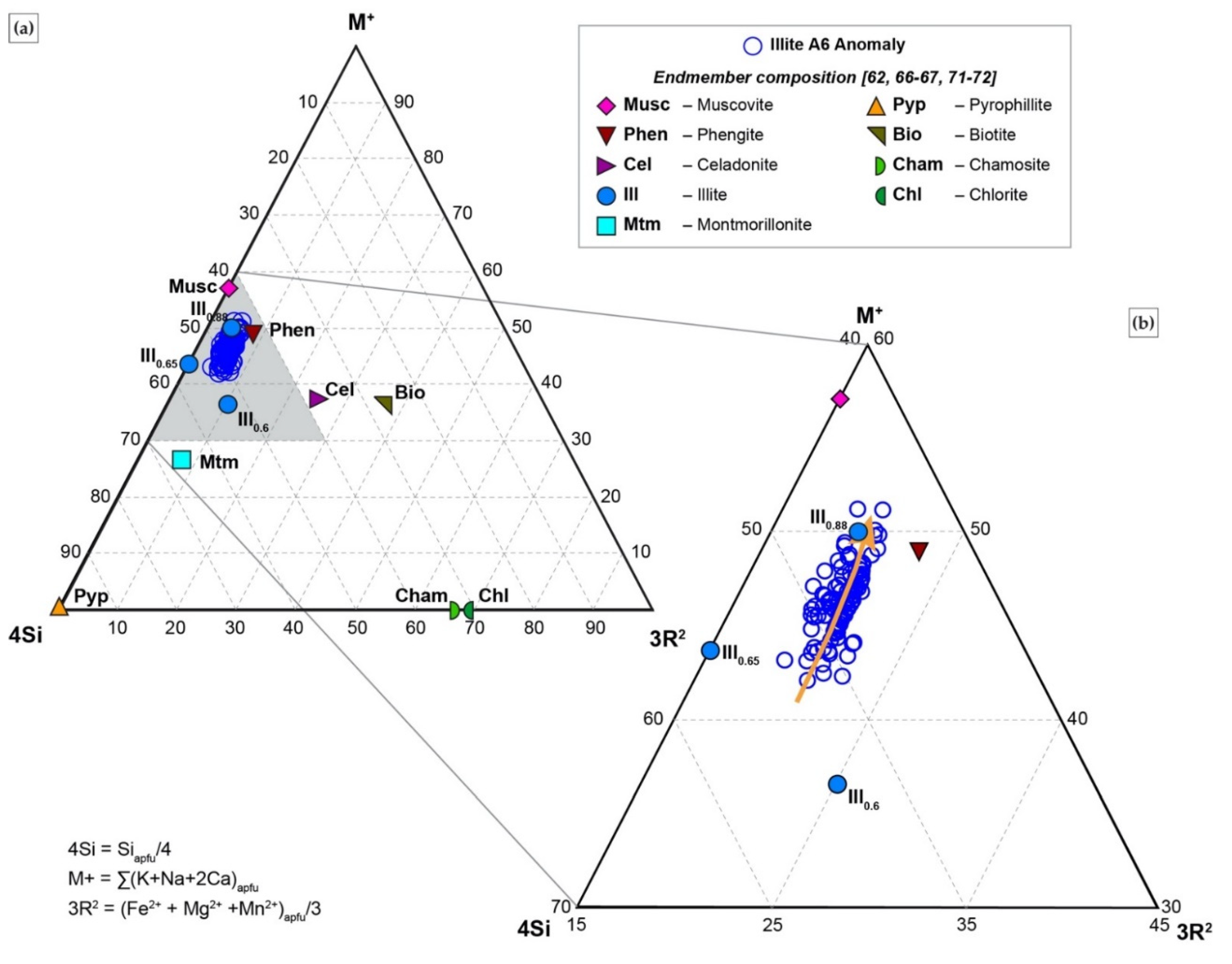
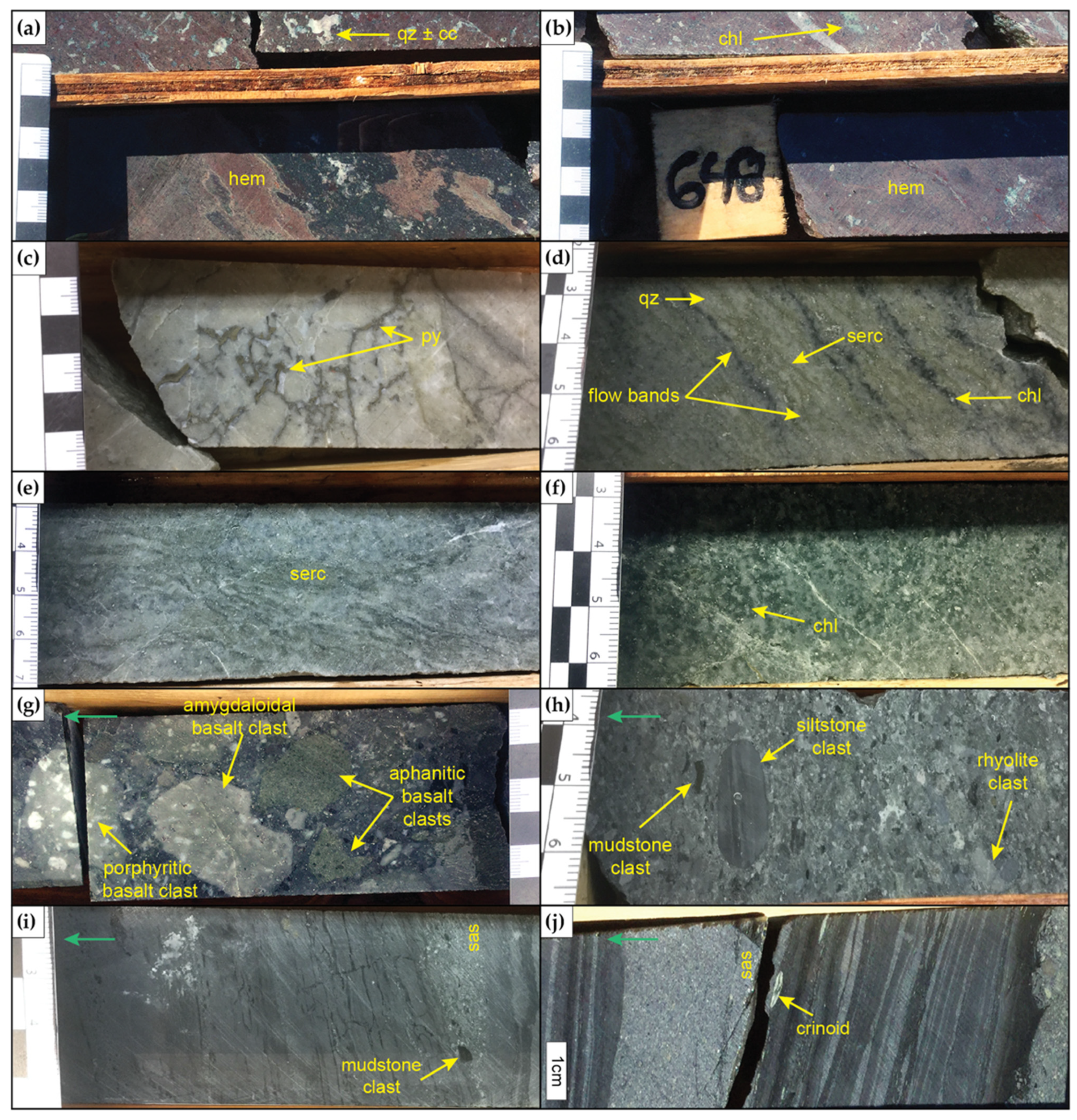
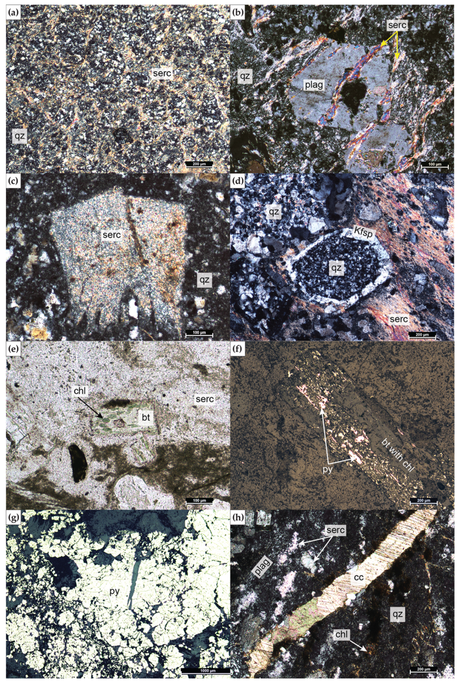
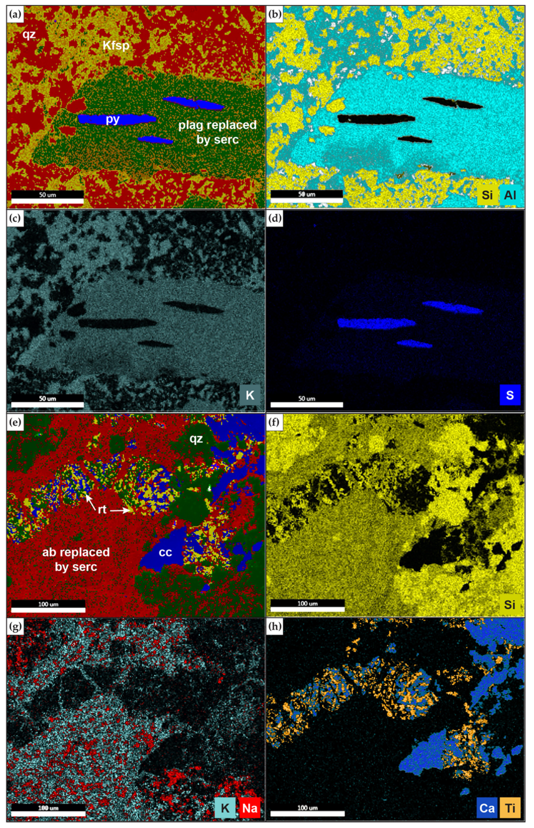
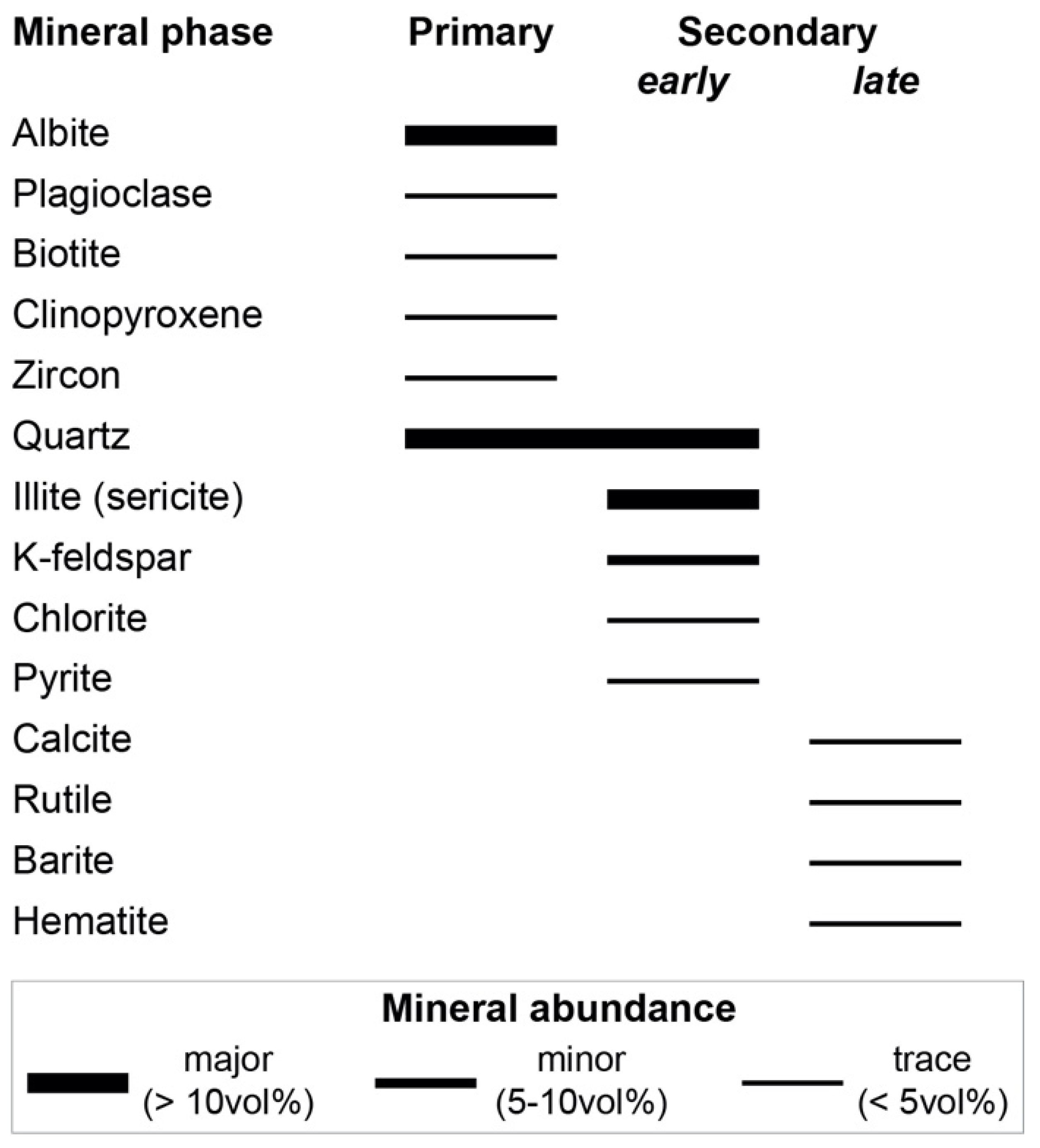
4.2. Alteration Mineralogy
4.2.1. SEM
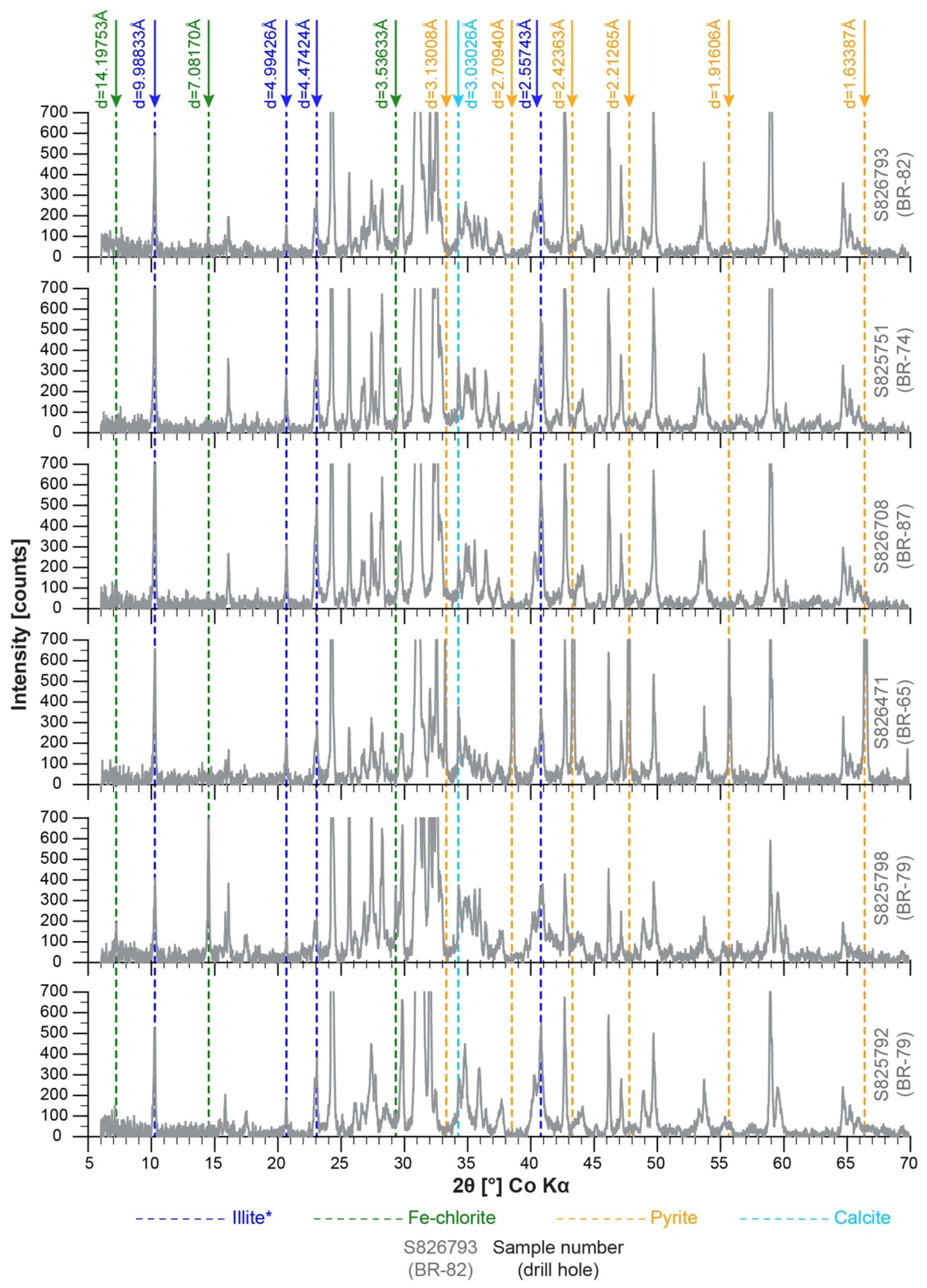
4.2.2. XRD
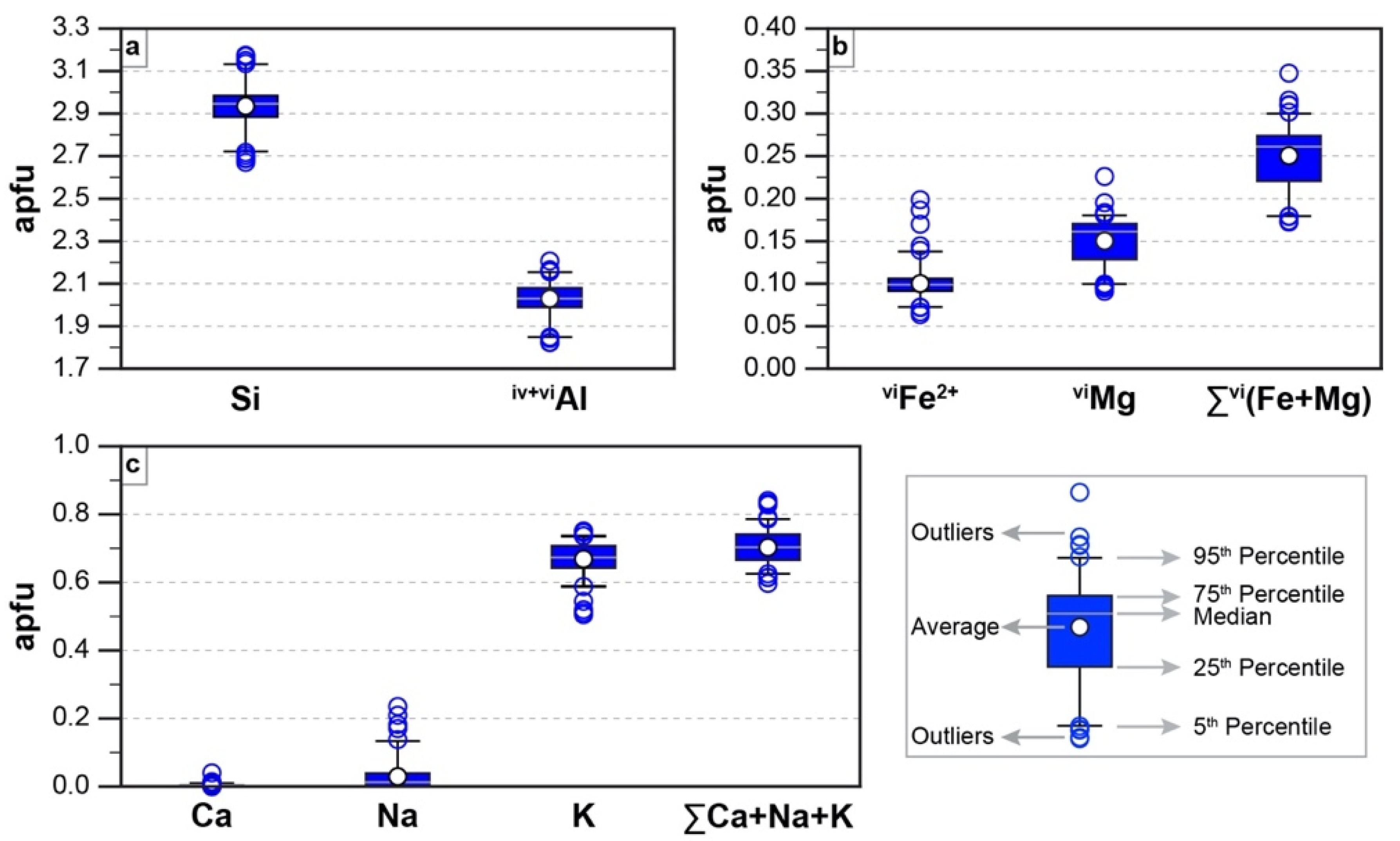
4.3. EMPA
| Element | Average | Stddev | Min | Max |
|---|---|---|---|---|
| SiO2 [wt%] | 50.02 | 1.52 | 45.78 | 54.16 |
| Al2O3 | 29.36 | 1.06 | 26.42 | 32.33 |
| FeO(t) | 2.04 | 0.41 | 1.32 | 4.09 |
| MgO | 1.72 | 0.30 | 1.05 | 2.58 |
| CaO | 0.08 | 0.07 | 0.00 | 0.64 |
| Na2O | 0.26 | 0.40 | 0.00 | 2.09 |
| K2O | 8.93 | 0.59 | 6.82 | 9.85 |
| Cr2O3 | 0.01 | 0.01 | 0.00 | 0.04 |
| SO3 | 0.02 | 0.06 | 0.00 | 0.63 |
| CuO | 0.02 | 0.02 | 0.00 | 0.11 |
| Total | 92.45 | 1.11 | 90.09 | 95.56 |
| H2O_calc | 7.55 | 1.11 | 4.44 | 9.91 |
| Na2O + K2O | 9.19 | 0.54 | 8.00 | 10.54 |
| Based on 11 oxygen atoms | ||||
| Si [apfu] | 2.94 | 0.10 | 2.67 | 3.17 |
| ivAl * | 0.65 | 0.00 | 0.65 | 0.65 |
| Subtotal | 3.59 | 0.10 | 3.32 | 3.82 |
| viAl | 1.38 | 0.08 | 1.17 | 1.56 |
| Fe2+ ** | 0.10 | 0.02 | 0.06 | 0.20 |
| Mg | 0.15 | 0.03 | 0.09 | 0.23 |
| Sum Octahedral | 1.63 | 0.08 | 1.36 | 1.74 |
| R2+ = Fe + Mg | 0.25 | 0.04 | 0.17 | 0.35 |
| viR2+/(viR2+ + viR3+) ≤ 0.25 | 0.15 | 0.02 | 0.10 | 0.23 |
| Ca | 0.01 | 0.00 | 0.00 | 0.04 |
| Na | 0.03 | 0.05 | 0.00 | 0.24 |
| K | 0.67 | 0.05 | 0.50 | 0.75 |
| Sum Interlayer | 0.70 | 0.05 | 0.60 | 0.84 |
| Total_no water | 5.92 | 0.13 | 5.65 | 6.26 |
| OH | 1.48 | 0.20 | 0.89 | 1.90 |
| Al_total | 2.03 | 0.08 | 1.82 | 2.21 |
| Cr | 0.00 | 0.00 | 0.00 | 0.00 |
| S | 0.00 | 0.00 | 0.00 | 0.03 |
| Cu | 0.00 | 0.00 | 0.00 | 0.00 |
| x = K + |Fe-Mg| | 0.72 | 0.06 | 0.53 | 0.83 |
| T[°C] = 267.95x + 31.50 | 225 | 16 | 173 | 253 |
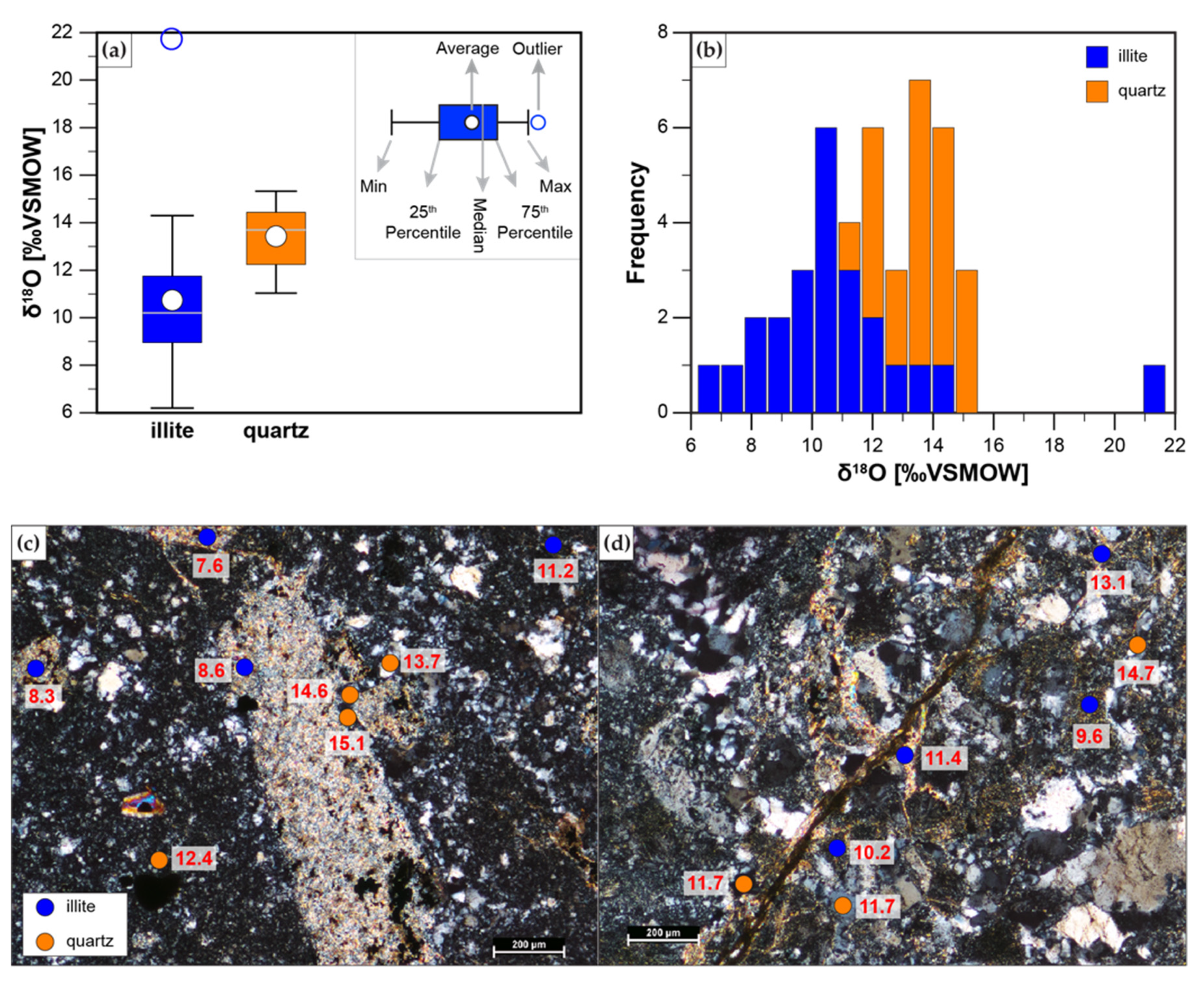
4.4. SIMS
5. Discussion
5.1. Potential for a VMS System


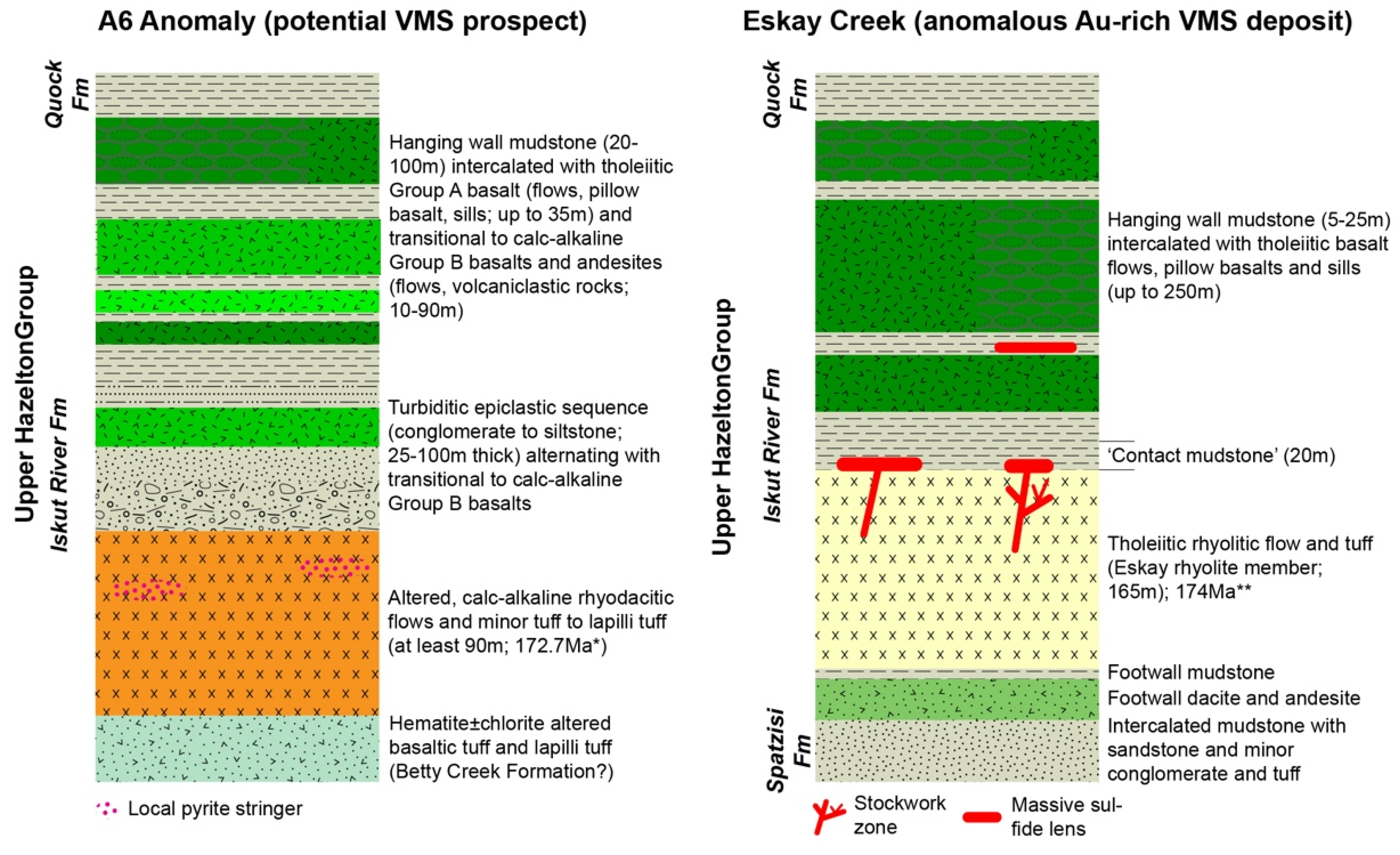
5.2. Comparison to Eskay Creek VMS Deposit and Tectonic Setting of A6 Anomaly
5.3. Alteration
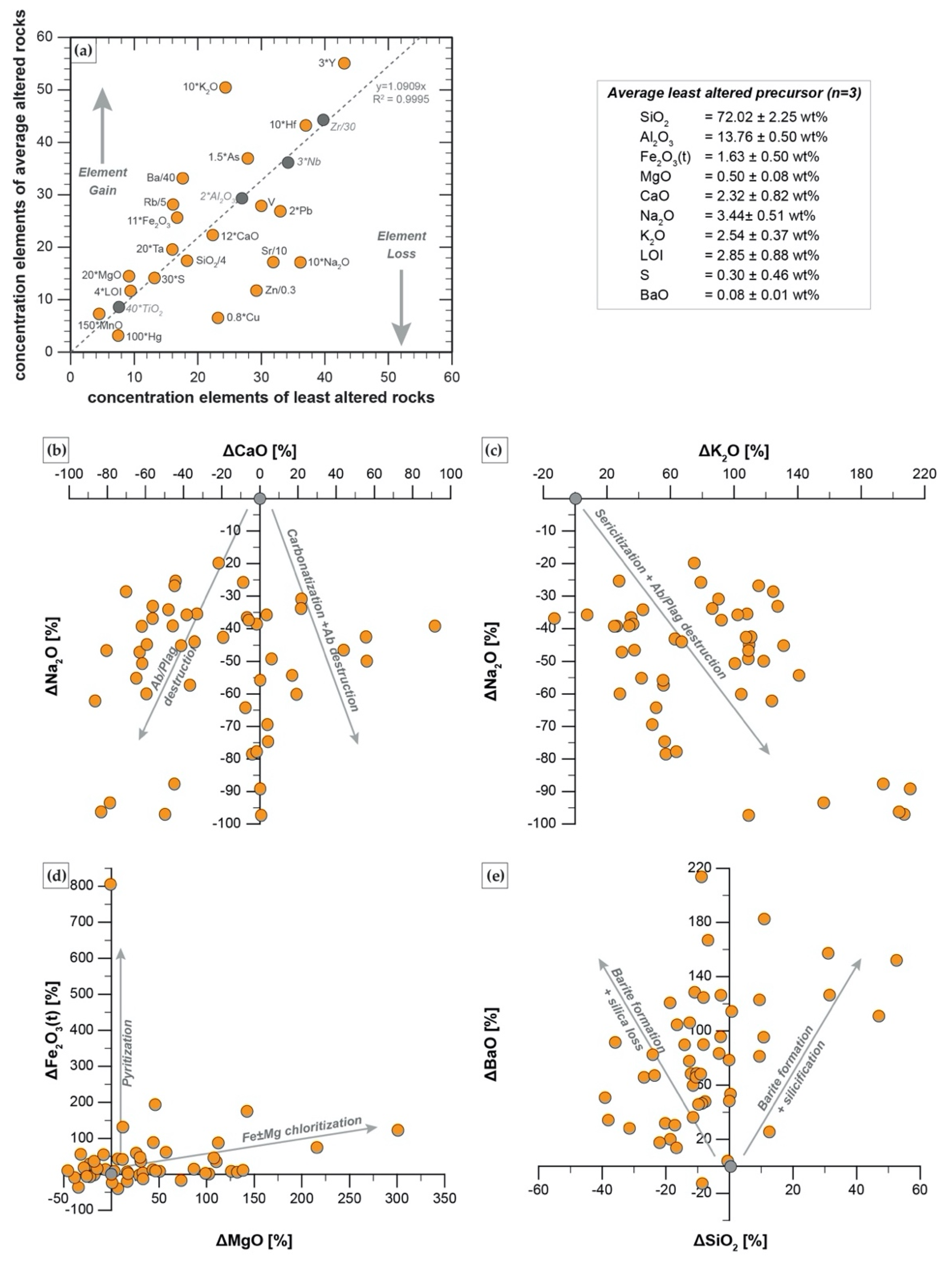
5.3.1. Isocon and Mass Balance Calculations
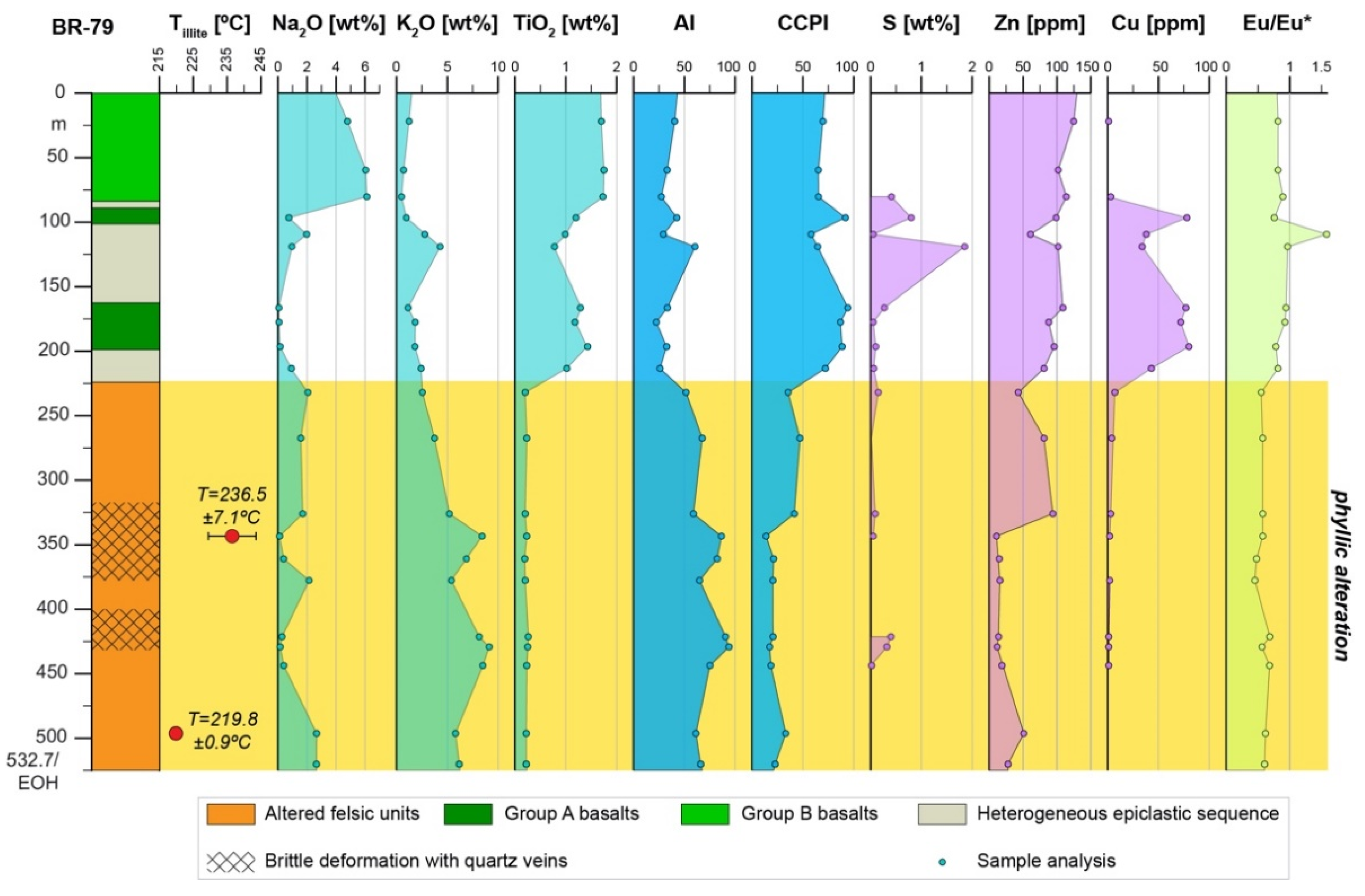
5.3.2. Alteration Geochemistry and Geothermometry

6. Conclusions
- Stratigraphy at the A6 Anomaly is comprised of altered felsic rhyodacites to trachytes that are overlain by a fining upward volcano-sedimentary sequence consisting of heterogeneous turbiditic sequence and mafic to intermediate volcanic rocks. This stratigraphy has late-Early to Middle Jurassic age (177–172.7 Ma) and is assigned here to the Iskut River Formation of the Upper Hazelton Group.
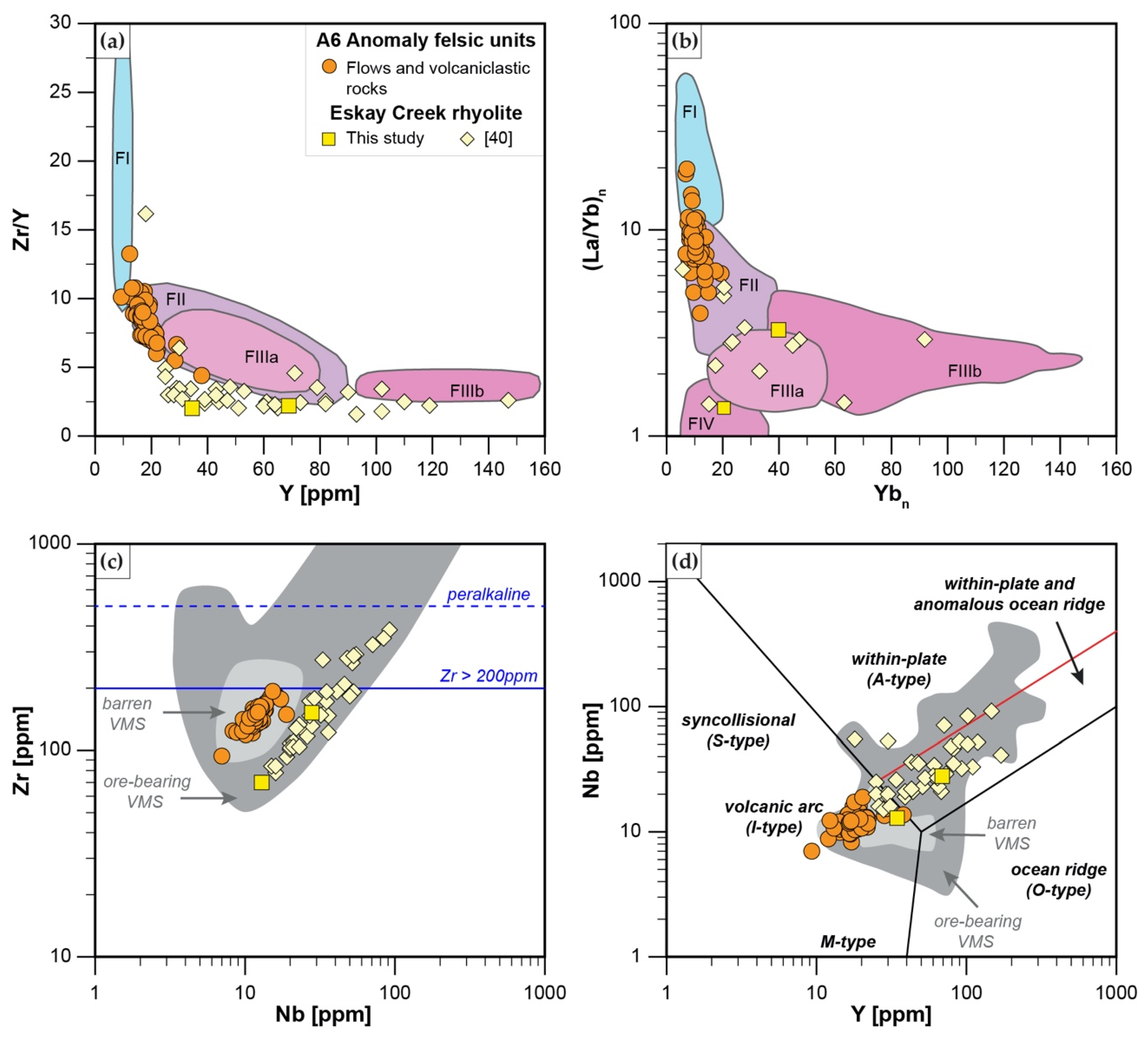
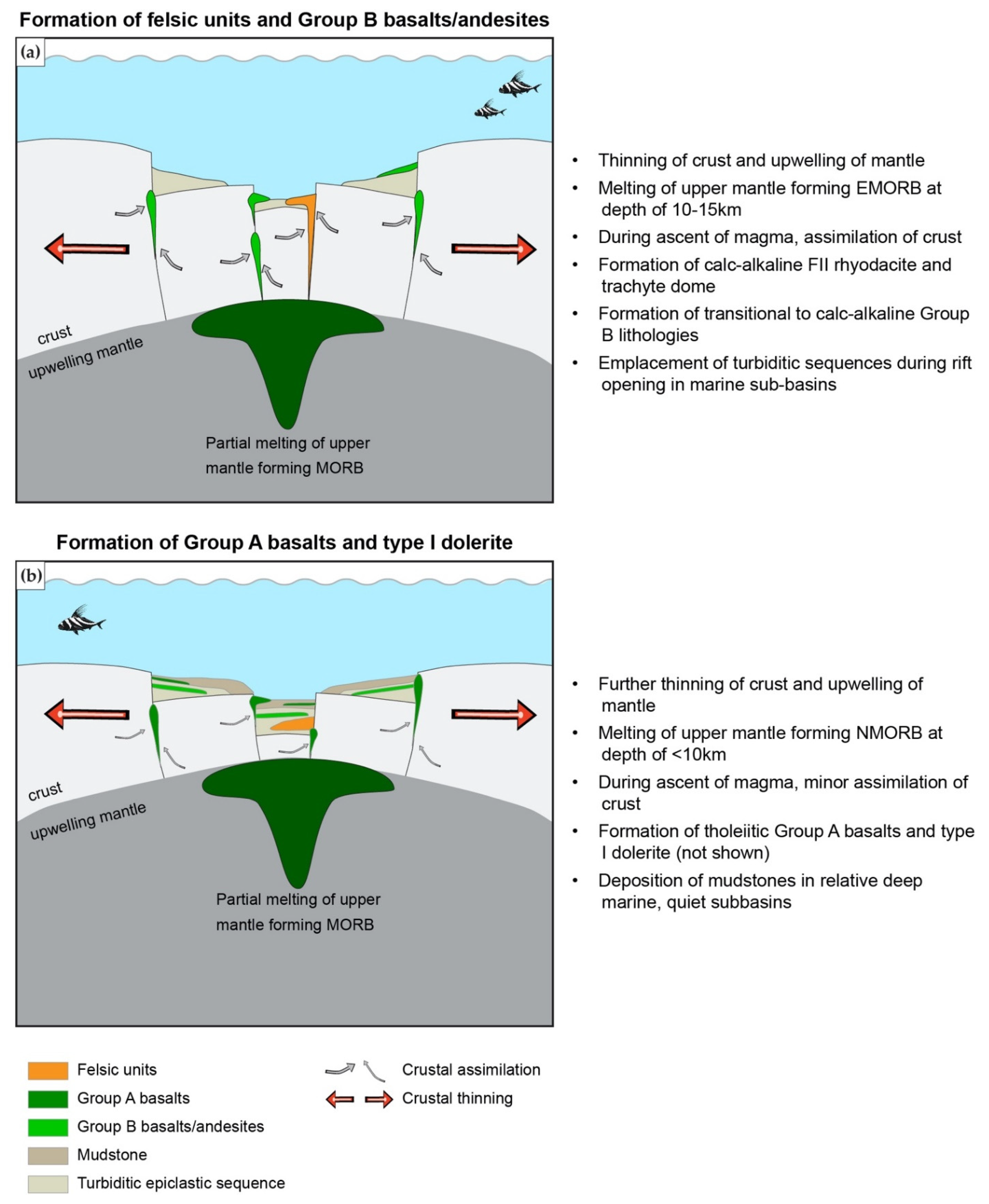
- Rhyodacites and trachytes have a calc-alkaline affinity and represent FII to minor FI rhyolites with Zr < 200 ppm, and a weakly decreasing REE pattern that has a weakly negative Eu anomaly. These units were formed by partial melting of an amphibole-plagioclase precursor at a melting depth of 10–15 km in an evolving back-basin.
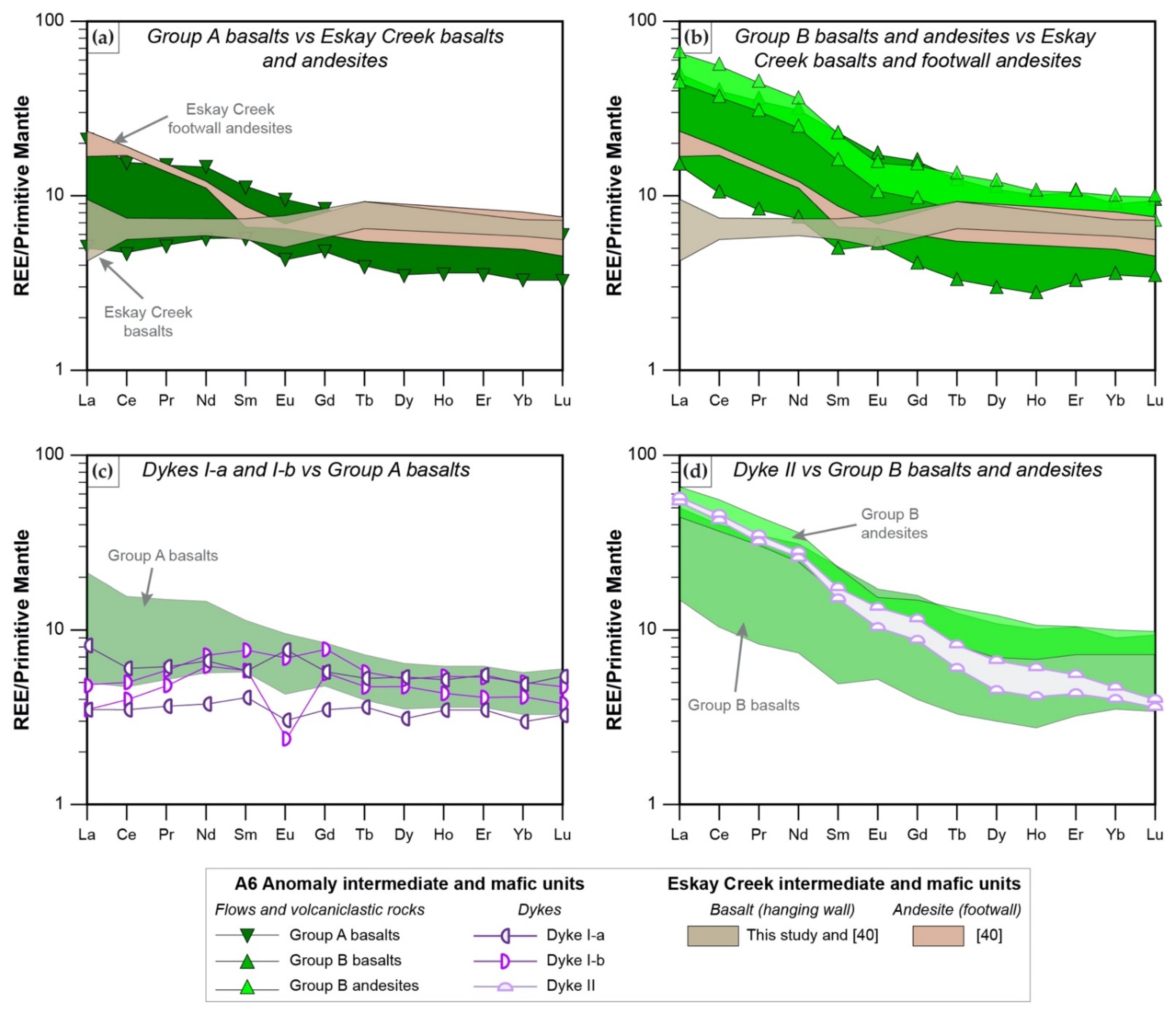
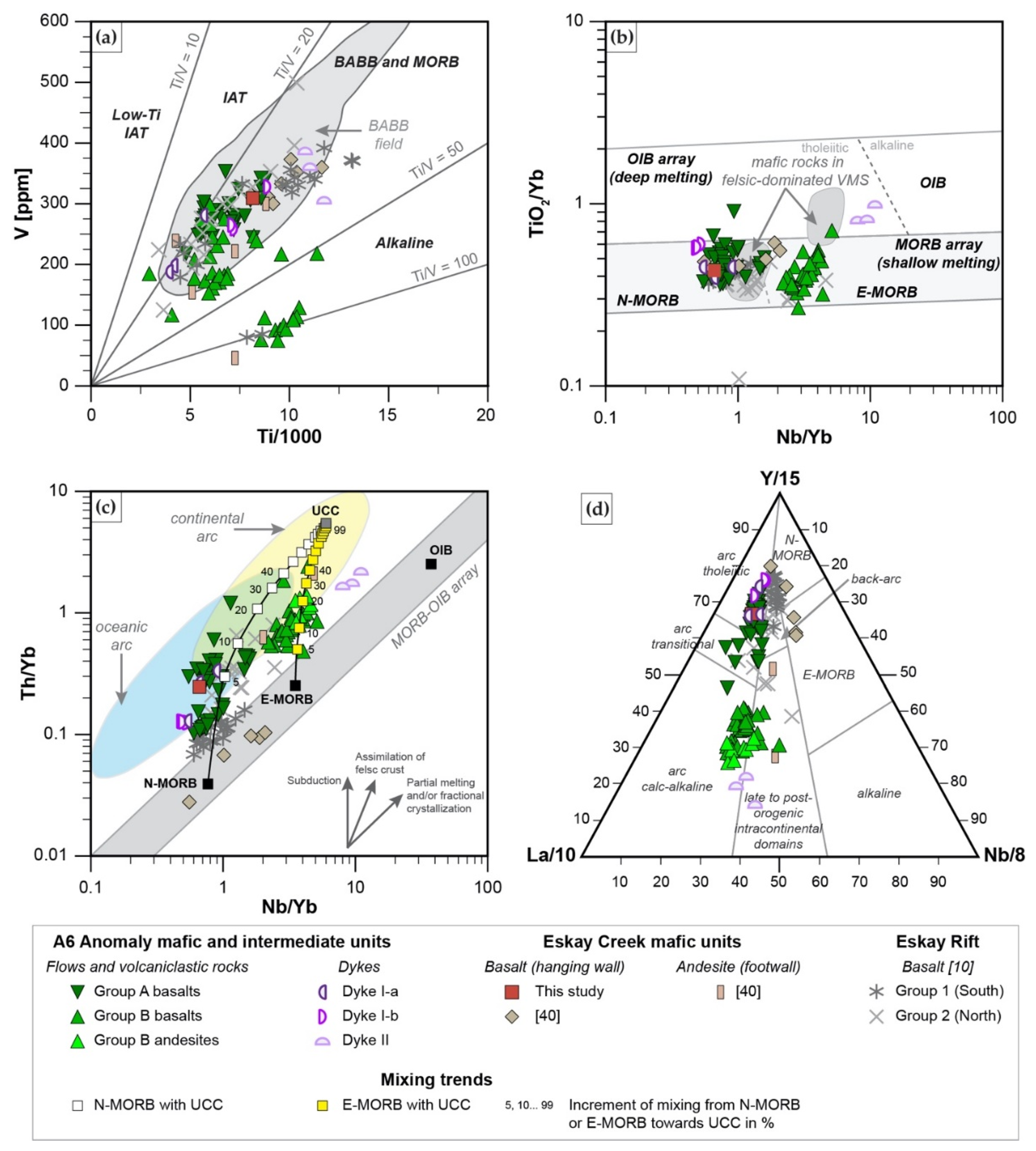
- Mafic units, which are distinguished into Group A basalts (tholeiitic, Nb/Yb < 1.6; slightly decreasing REE pattern) and Group B basalts and andesites (transitional to calc-alkaline, Nb/Yb > 2.2; strongly decreasing REE pattern), represent MORB with varying degrees of crust assimilation. Group B basalts, which occur spatially in the hanging wall of altered felsic units, are formed in a similar back-arc setting to those of rhyodacites to trachytes. In contrast, Group A basalts which occur predominantly in the upper part of the stratigraphy formed when the evolving back arc basin thinned due to extension, resulting in less crustal contamination compared to Group B rocks; this indicates the presence of a rift basin east of the main Eskay rift.
- Felsic and mafic units at the A6 Anomaly are ambiguous in their potential to host an ore-bearing VMS deposit, since they have characteristics of both barren VMS systems (e.g., absence of subvolcanic intrusion that provide heat and metals; felsic units with geochemistry common in VMS barren systems and low metal content; lack of distinct sulfide stringers common in stockwork zones beneath massive sulfide lenses) and ore-bearing VMS systems (e.g., association with shallow melting mafic units such as Group A basalts; pre-dominant FII affinity; formation in evolving back-arc rift common for VMS formation). Hence, further exploration in the area should focus on identifying a shallow subvolcanic tholeiitic felsic intrusion that could have provided heat and base metals, and on further identifying the stratigraphy and geochemistry of igneous units.
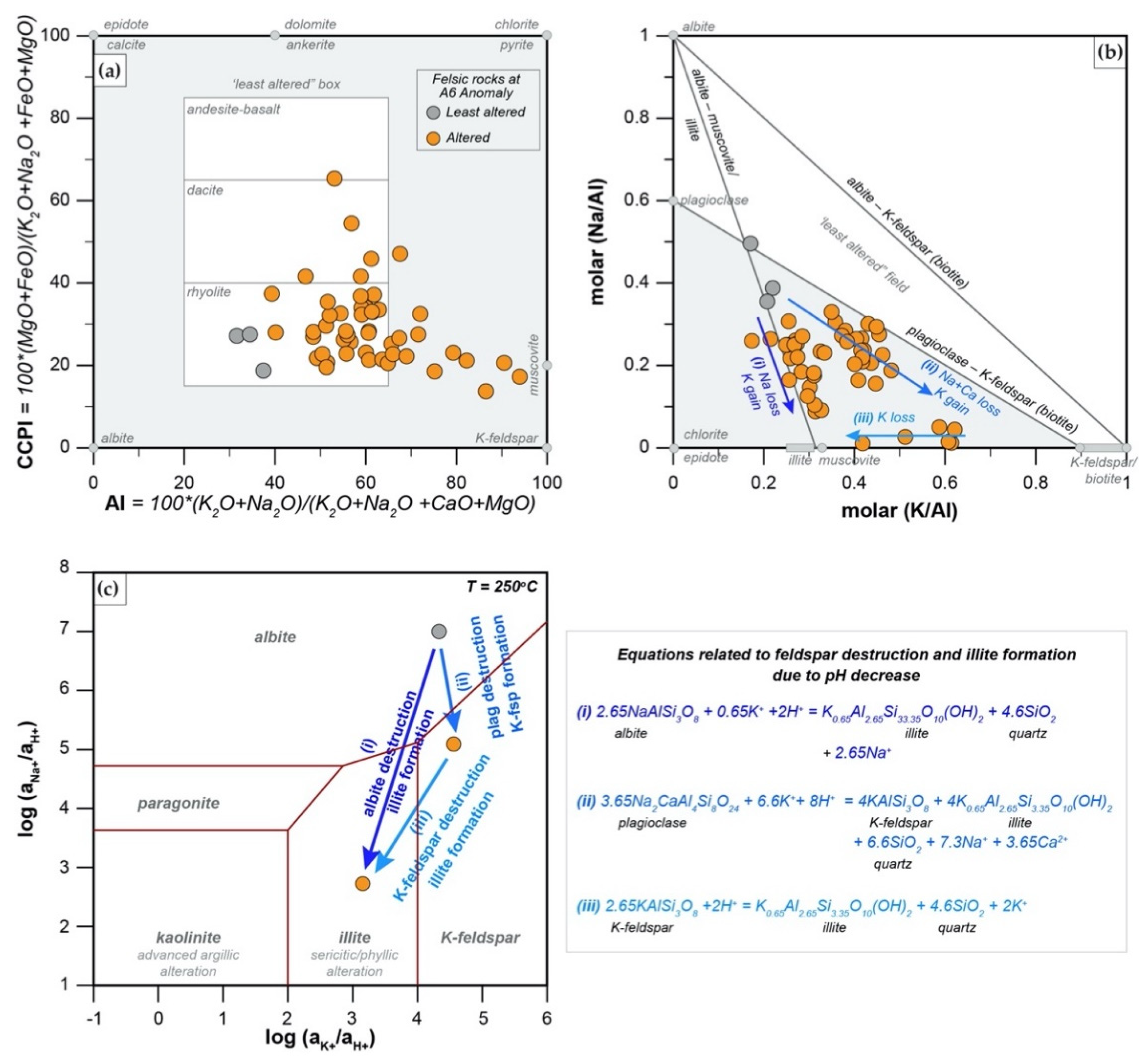
- The alteration assemblage in the altered felsic units is laterally and vertically homogeneous, defined by phyllic alteration with quartz—illite–K-feldspar ± chlorite ± pyrite ± calcite ± barite ± rutile. Illite is of I/S and almost endmember illite composition and formed from feldspar (albite, plagioclase, K-feldspar) destruction by mildly acidic (pH = 4–5.5), oxidized fluids at temperatures of 200–250 °C. The alteration represents distal footwall alteration, presumably in a semiconformable alteration zone, and lacks significant sulfide stringers and metal enrichment. Hydrothermal fluids, despite favorable fluid conditions, in particular for Zn ± Pb ± Ag transport, were relatively metal barren.
Supplementary Materials
Author Contributions
Funding
Data Availability Statement
Acknowledgments
Conflicts of Interest
References
- Board, W.S.; McLeish, D.F.; Greig, C.J.; Bath, O.E.; Ashburner, J.E.; Murphy, T.; Friedman, R.M. The brucejack Au-Ag deposit, Northwest British Columbia, Canada: Multistage porphyry to epithermal alteration, mineralization, and deposit formation in an island-arc setting. In Geology of the World’s Major Gold Deposits and Provinces; Sillitoe, R.H., Goldfarb, R.J., Robert, F., Simmons, S.F., Eds.; Special Publication Number 23; The Society of Economic Geologists: Boulder, CO, USA, 2020; pp. 289–312. [Google Scholar]
- Childe, F. U-Pb geochronology and Nd and Pb isotope characteristics of the Au-Ag-rich Eskay Creek volcanogenic massive sulfide deposit, British Columbia. Econ. Geol. 1996, 91, 1209–1224. [Google Scholar] [CrossRef]
- Cutts, J.A.; McNicoll, V.J.; Zagorevski, A.; Anderson, R.G.; Martin, K. U-Pb geochronology of the Hazelton Group in the McTagg anticlinorium, Iskut River area, northwestern British Columbia. Geol. Fieldwork 2014, 2015-1, 87–101. [Google Scholar]
- Gagnon, J.F.; Barresi, T.; Waldron, J.W.; Nelson, J.L.; Poulton, T.P.; Cordey, F. Stratigraphy of the upper Hazelton Group and the Jurassic evolution of the Stikine terrane, British Columbia. Can. J. Earth. Sci. 2012, 49, 1027–1052. [Google Scholar] [CrossRef]
- Lewis, P.D. Geological maps of the Iskut river area, Northwest British Columbia (104B/08, 09, 10 & part of 104B/01, 07, 11), 1:50,000-scale maps, legend and notes. Geosci. B. C. Rep. 2013, 5, 1. [Google Scholar]
- Nelson, J.; Waldron, J.; van Straaten, B.; Zagorevski, A.; Rees, C. Revised stratigraphy of the Hazelton Group in the Iskut River region, northwestern British Columbia. Geol. Fieldwork 2018, 2018-1, 15–38. [Google Scholar]
- Febbo, G.E.; Kennedy, L.A.; Nelson, J.L.; Savell, M.J.; Campbell, M.E.; Creaser, R.A.; Friedman, R.M.; van Straaten, B.I.; Stein, H.J. The evolution and structural modification of the supergiant mitchell au-cu porphyry, Northwestern British Columbia. Econ. Geol. 2019, 114, 303–324. [Google Scholar] [CrossRef]
- Nelson, J.L.; Colpron, M.; Israel, S. The Cordillera of British Columbia, Yukon, and Alaska. In Tectonics, Metallogeny, and Discovery:The North American Cordillera and Similar Accretionary Settings; Colpron, M., Bissig, T., Rusk, B.G., Thompson, J.F.H., Eds.; Special Publication No. 17; The Society of Economic Geologists: Boulder, CO, USA, 2013; pp. 53–109. [Google Scholar]
- Barresi, T.; Nelson, J.L.; Dostal, J.; Friedman, R.; Gibson, H. Evolution of the Hazelton arc near Terrace, British Columbia: Stratigraphic, geochronological, and geochemical constraints on a Late Triassic–Early Jurassic arc and Cu–Au porphyry belt. Can. J. Earth. Sci. 2015, 52, 466–494. [Google Scholar] [CrossRef]
- Barresi, T.; Nelson, J.L.; Dostal, J. Geochemical constraints on magmatic and metallogenic processes: Iskut River Formation, volcanogenic massive sulfide-hosting basalts, NW British Columbia, Canada. Can. J. Earth Sci. 2015, 52, 1–20. [Google Scholar] [CrossRef]
- Bartsch, R.D. Eskay Creek area stratigraphy, update. Geol. Fieldwork 1993, 1992-1, 517–520. [Google Scholar]
- Macdonald, A.J.; Lewis, P.D.; Thompson, J.F.H.; Nadaraju, G.; Bartsch, R.; Bridge, D.J.; Rhys, D.A.; Roth, T.; Kaip, A.; Godwin, C.I.; et al. Metallogeny of an early to middle jurassic arc, Iskut River area, northwestern British Columbia. Econ. Geol. 1996, 91, 1098–1114. [Google Scholar] [CrossRef]
- Hart, T.R.; Gibson, H.L.; Lesher, C.M. Trace element geochemistry and petrogenesis of felsic volcanic rocks associated with volcanogenic massive Cu-Zn-Pb sulfide deposits. Econ. Geol. 2004, 99, 1003–1013. [Google Scholar] [CrossRef]
- Gibson, H.; Galley, A. Volcanogenic Massive sulphide deposits of the Archean Noranda District, Quebec. In Mineral Deposits of Canada: A Synthesis of Major Deposit Types, District Metallogeny, the Evolution of Geological Provinces, and Exploration Methods; Goodfellow, W.D., Ed.; Special Publication No. 5; Mineral Deposits Division, Geological Association of Canada: St. John’s, NL, Canada, 2007; pp. 533–552. [Google Scholar]
- Piercey, S.J. An overview of the use of petrochemistry in the regional exploration for volcanogenic massive sulfide (VMS) deposits. In Proceedings of the Fifth Decennial International Conference on Mineral Exploration, Toronto, ON, Canada, 9–12 September 2007; pp. 223–246. [Google Scholar]
- Piercey, S.J. An overview of petrochemistry in the regional exploration for volcanogenic massive sulphide (VMS) deposits. Geochem. Explor. Environ. Anal. 2010, 10, 119–136. [Google Scholar] [CrossRef]
- Galley, A.; Hannington, M.; Jonasson, I. Volcanogenic massive sulphide deposits. In Mineral Deposits of Canada: A Synthesis of Major Deposit-Types, District Metallogeny, the Evolution of Geological Provinces, and Exploration Methods; Goodfellow, W.D., Ed.; Special Publication No. 5; Geological Association of Canada, Mineral Deposits Division: St. John’s, NL, Canada, 2005; pp. 141–161. [Google Scholar]
- Alldrick, D.J.; Nelson, J.L.; Barresi, T. Geology and mineral occurrences of the upper Iskut River area: Tracking the Eskay rift through northern British Columbia. Geol. Fieldwork 2005, 2004-2, 2–39. [Google Scholar]
- Anderson, R.G. Anderson, R.G.A Mesozoic stratigraphic and plutonic framework for northwestern Stikinia (Iskut River area), northwestern British Columbia, Canada. In Mesozoic Paleogeography of the Western United States–II; Dunne, G.C., MacDougall, K.A., Eds.; Society of Economic Paleontologists and Mineralogists, Pacific Section: Tulsa, OK, USA, 1993; Volume 71, pp. 477–494. [Google Scholar]
- Cas, R.A.F. Submarine volcanism; eruption styles, products, and relevance to understanding the host-rock successions to volcanic-hosted massive sulfide deposits. Econ. Geol. 1992, 87, 511–541. [Google Scholar] [CrossRef]
- Gibson, H.; Morton, R.L.; Hudak, G.J. Submarine volcanic processes, deposits, and environments favorable for the loaction of volcanic-associated massive sulfide deposits. In Volcanic-Associated Massive Sulfide Deposits: Processes and Examples in Modern and Ancient Settings; Barrie, C.T., Hannington, M.D., Eds.; Society of Economic Geologists: Boulder, CO, USA, 1999; Volume 8, pp. 13–51. [Google Scholar]
- Gibson, H.L.; Allen, R.L.; Riverin, G.; Lane, T.E. The VMS model: Advances and application to exploration targeting. In Proceedings of the Exploration 07: Fifth Decennial International Conference on Mineral Exploration, Toronto, ON, Canada, 9–12 September 2007; pp. 713–730. [Google Scholar]
- Brueckner, S.M. Preliminary Geological and Geochemical Assessment of the A6 Anomaly as Potential Volcanogenic Massive Sulfide (VMS) Exploration Target; Personal Report: Vancouver, BC, Canada, 2020; p. 20. [Google Scholar]
- Colpron, M.; Nelson, J.L.; Murphy, D.C. A tectonostratigraphic framework for the pericratonic terranes of the northern Canadian Cordillera. In Paleozoic Evolution and Metallogeny of Pericratonic Terranes at the Ancient Pacific Margin of North America, Canadian and Alaskan Cordillera; Colpron, M., Nelson, J., Eds.; GAC Special Paper: St. John’s, NL, Canada, 2006; Volume 45, pp. 1–23. [Google Scholar]
- Mihalynuk, M.G.; Nelson, J.; Diakow, L.J. Cache Creek terrane entrapment: Oroclinal paradox within the Canadian Cordillera. Tectonics 1994, 13, 575–595. [Google Scholar] [CrossRef]
- Monger, J.W.H. Cordilleran tectonics: A Canadian perspective. Bull. Soc. Géol. France 1984, 26, 255–278. [Google Scholar] [CrossRef]
- Monger, J.W.H.; Price, R.A. The Canadian Cordillera: Geology and tectonic evolution. Can. Soc. Explor. Geophys. Rec. 2002, 17–36. [Google Scholar]
- Marsden, H.; Thorkelson, D.J. Geology of the Hazelton Volcanic Belt in British Columbia: Implications for the Early to Middle Jurassic Evolution of Stikinia. Tectonics 1992, 11, 1266–1287. [Google Scholar] [CrossRef]
- Tipper, H.W.; Richards, T.A. Jurassic Stratigraphy and History of North-Central British Columbia; Bulletin 270; Geological Survey of Canada: Ottawa, ON, Canada, 1976. [Google Scholar]
- Evenchick, C.A.; McNicoll, V.J.; Snyder, L.D. Stratigraphy, geochronology, and geochemistry of the Georgie River area, northwest British Columbia, and implications for mineral exploration. Can. J. Earth Sci. 2004, 41, 199–216. [Google Scholar] [CrossRef]
- Evenchik, C.A.; Poulton, T.P.; McNicoll, V.J. Nature and significance of the diachronous contact between the Hazelton and Bowser Lake groups (Jurassic), north-central British Columbia. Bull. Can. Petrol. Geol. 2010, 58, 235–267. [Google Scholar] [CrossRef]
- Cohen, K.M.; Finney, S.C.; Gibbard, P.L.; Fan, J.X. The ICS International Chronostratigraphic Chart. Episodes 2013, 36, 199–204. [Google Scholar] [CrossRef] [PubMed]
- Nelson, J.; Kyba, J. Structural and stratigraphic control of porphyry and related mineralization in the Treaty Glacier–KSM–Brucejack–Stewart trend of western Stikinia. Geol. Fieldwork 2014, 2014-1, 111–140. [Google Scholar]
- Kirkham, R.V.; Margolis, J. Overview of the Sulphurets area, northwestern British Columbia. In Porphyry Deposits of the NorthWestern Cordillera of North America; Schroeter, T.G., Ed.; Special Volume 46; Canadian Institute of Mining, Metallurgy and Petroleum: Westmount, QC, Canada, 1995; pp. 473–483. [Google Scholar]
- Macdonald, A.J. Lithostratigraphy and geochronometry, Brucejack Lake, northwestern British Columbia (104B/08E). Geol. Fieldwork 1993, 1993-1, 315–323. [Google Scholar]
- Barresi, T.; Nelson, J.L.; Alldrick, D.J.; Dostal, J. Pillow basalt ridge facies-detailed mapping of Eskay Creek equivalent stratigraphy. Geol. Fieldwork 2005, 2004-3, 41–52. [Google Scholar]
- Sherlock, R.L.; Roth, T.; Spooner, E.T.C.; Bray, C.J. Origin of the Eskay Creek precious metal-rich volcanogenic massive sulfide deposit; fluid inclusion and stable isotope evidence. Econ. Geol. 1999, 94, 803–824. [Google Scholar] [CrossRef]
- Kalanchey, R.; Elfen, S.; Weston, S.; Ulansky, S.; Dance, A.; Zurow, G.; Hamilton, W. Skeena Resources Limited, Eskay Creek Project, British Columbia, Canada: NI 43-101 Technical Report on Preliminary Economic Assessment; Ausenco Engineering Canada Inc.: Vancouver, BC, Canada, 2019; p. 364. [Google Scholar]
- Barresi, T.; Dostal, J. Geochemistry and petrography of uppermost Hazelton Group volcanics: VHMS favourable stratigraphy in the Iskut River and Telegraph Creek map areas, northwest B.C. Geol. Fieldwork 2005, 2004-2, 30–40. [Google Scholar]
- Barrett, T.J.; Sherlock, R.L. Geology, lithogeochemistry and volcanic setting of the Eskay Creek Au-Ag-Cu-Zn deposit, northwestern British Columbia. Explor. Min. Geol. 1996, 5, 339–368. [Google Scholar]
- Roth, T.; Thompson, J.F.H.; Sillitoe, R.H. The precious metal-rich Eskay Creek deposit, northwestern British Columbia. In Volcanic-Associated Massive Sulfide Deposits: Processes and Examples in Modern and Ancient Settings; Barrie, C.T., Hannington, M.D., Eds.; Society of Economic Geologists: Littleton, CO, USA, 1999; Volume 8, pp. 357–373. [Google Scholar]
- Febbo, G.E.; Kennedy, L.A.; Savell, M.; Creaser, R.A.; Friedman, R.M. Geology of the Mitchell Au-Cu-Ag-Mo porphyry deposit, northwestern British Columbia, Canada. Geol. Fieldwork 2015, 2015-1, 59–86. [Google Scholar]
- Margolis, J. Geology and intrusion-related copper-gold mineralization, Sulphurets, British Columbia. Ph.D Thesis, University of Oregon, Eugene, OR, USA, 1993. [Google Scholar]
- Tombe, S.P.; Richards, J.P.; Greig, C.J.; Board, W.S.; Creaser, R.A.; Muehlenbachs, K.A.; Larson, P.B.; DuFrane, S.A.; Spell, T. Origin of the high-grade Early Jurassic Brucejack epithermal Au-Ag deposits, Sulphurets Mining Camp, northwestern British Columbia. Ore. Geol. Rev. 2018, 95, 480–517. [Google Scholar] [CrossRef]
- Pretivm Resouces Inc. U-Pb Geochronology on the Bowser Property; Pretivm Resouces Inc.: Vancouver, BC, Canada, 2020; p. 20. [Google Scholar]
- Pouchou, J.L.; Pichoir, F. A new model for quantitative X-ray microanalysis, Part II: Application to in depth analysis of heterogeneous samples. Rech. Aérosp. 1984, 5, 349–367. [Google Scholar]
- Riciputi, L.R.; Paterson, B.A.; Ripperdan, R.L. Measurement of light stable isotope ratios by SIMS: Matrix effects for oxygen, carbon, and sulfur isotopes in minerals. Int. J. Mass. Spec. 1998, 178, 81–112. [Google Scholar] [CrossRef]
- Coplen, T.B. Guidelines and recommended terms for expression of stable-isotope-ratio and gas-ratio measurement results. Rapid Commun. Mass Spectrom. 2011, 25, 2538–2560. [Google Scholar] [CrossRef] [PubMed]
- Coplen, T.B. Reporting of stable hydrogen, carbon, and oxygen isotopic abundances (Technical Report). Pure Appl. Chem. 1994, 66, 273–276. [Google Scholar] [CrossRef]
- Coplen, T.B. Report of Stable Isotopic Composition Reference Material VSMOW (Hydrogen and Oxygen Isotopes in Water); United States Geological Survey, Reston Stable Isotope Laboratory: Reston, VA, USA, 2020; p. 4. [Google Scholar]
- Gonfiantini, R. Standards for stable isotope measurements in natural compounds. Nature 1978, 271, 534–536. [Google Scholar] [CrossRef]
- Kelly, J.L.; Fu, B.; Kita, N.T.; Valley, J.W. Optically continuous silcrete quartz cements of the St. Peter Sandstone: High precision oxygen isotope analysis by ion microprobe. Geochim. Cosmochim. Acta 2007, 71, 3812–3832. [Google Scholar] [CrossRef]
- Ross, P.-S.; Bédard, J.H. Magmatic affinity of modern and ancient subalkaline volcanic rocks determined from trace-element discriminant diagrams. Can. J. Earth Sci. 2009, 46, 823–839. [Google Scholar] [CrossRef] [Green Version]
- Rollinson, H.R. Using Geochemical Data: Evaluation, Presentation, Interpretation; Longman Scientific and Technical: London, UK, 1993. [Google Scholar]
- Boynton, W.V. Geochemistry of Rare Earth Elements: Meteorite Studies. In Rare Earth Element Geochemistry; Henderson, P., Ed.; Elsevier: New York, NY, USA, 1984; pp. 63–114. [Google Scholar] [CrossRef]
- Nakamura, N. Determination of REE, Ba, Fe, Mg, Na and K in carbonaceous and ordinary chondrites. Geochim. Cosmochim. Acta 1974, 38, 757–775. [Google Scholar] [CrossRef]
- Pearce, J.A. A User’s Guide to Basalt Discrimination Diagrams. In Trace Element Geochemistry of Volcanic Rocks: Applications for Massive Sulphide Exploration; Wyman, D.A., Ed.; Short Course Notes; Geological Assocaition of Canada: St. John’s, NL, Canada, 1996; Volume 12, pp. 79–113. [Google Scholar]
- Sun, S.S.; McDonough, W.F. Chemical and isotopic systematics of oceanic basalts: Implications for mantle composition and processes. Geol. Soc. Spec. Publ. 1989, 42, 313–345. [Google Scholar] [CrossRef]
- Johnson, G. Alteration Mineralogy and Chemistry of Felsic Volcanic Flows of the Jurassic Iskut River Formation at the A6 Anomaly, North-Central British Columbia; University of Manitoba: Winnipeg, MB, Canada, 2021. [Google Scholar]
- Battaglia, S. Variations in the chemical composition of illite from five geothermal fields: A possible geothermometer. Clays Clay Miner. 2004, 39, 501–510. [Google Scholar] [CrossRef]
- Meunier, A.; El Albani, A. The glauconite-Fe-illite-Fe-smectite problem: A critical review. Terra Nova 2007, 19, 95–104. [Google Scholar] [CrossRef]
- López-Quirós, A.; Sánchez-Navas, A.; Nieto, F.; Escutia, C. New insights into the nature of glauconite. Am. Min. 2020, 105, 674–686. [Google Scholar] [CrossRef]
- Rieder, M.; Cavazzini, G.; D’yakonov, Y.S.; Frank-Kamenetskii, V.A.; Gottardi, G.; Guggenheim, S.; Koval’, P.W.; Müller, G.; Neiva, A.M.R.; Radoslovich, E.W.; et al. Nomenclature of the Micas. Clays Clay Miner. 1998, 46, 586–595. [Google Scholar] [CrossRef]
- Rosenberg, P.E. The nature, formation, and stability of end-member illite: A hypothesis. Am. Min. 2002, 87, 103–107. [Google Scholar] [CrossRef]
- Aja, S.U. A Hydrothermal Study of Illite Stability Relationships between 25 and 250 °C and Pv ¼ PH2O; Washington State University: Washington, DC, USA, 1989. [Google Scholar]
- Aja, S.U. On the Thermodynamic Stability of Illite and I-S Minerals. Clays Clay Miner. 2020, 67, 518–536. [Google Scholar] [CrossRef]
- Meunier, A.; Velde, B. Solid solutions in I/S mixed-layer minerals and illite. Am. Min. 1989, 74, 1106–1112. [Google Scholar]
- Środoń, J.; Elsass, F.; McHardy, W.J.; Morgan, D.J. Chemistry of illite-smectite inferred from TEM measurements of fundamental particles. Clay Miner. 1992, 27, 137–158. [Google Scholar] [CrossRef]
- Yates, D.M.; Rosenberg, P.E. Formation and stability of end-member illite: II. Solid equilibration experiments at 100 to 250 °C. and Pv,soln. Geochim. Cosmochim. Acta 1997, 61, 3135–3144. [Google Scholar] [CrossRef]
- Reich, M.; Kesler, S.E.; Utsonomiya, S.; Palenik, C.S.; Chryssoulis, S.; Ewing, R.C. Solubility of gold in arsenian pyrite. Geochim. Cosmochim. Acta 2005, 69, 2781–2796. [Google Scholar] [CrossRef]
- Newman, A.C.D.; Brown, G. The chemical constitution of clays. In Chemistry of Clays Clay Min; Newman, A.C.D., Ed.; Monograph No. 6; Longman Scientific and Technical: London, UK, 1987; pp. 1–128. [Google Scholar]
- International Mineralogical Association. The New IMA List of Minerals—A Work in Progress 2021. Available online: http://cnmnc.main.jp/ (accessed on 28 May 2021).
- Hokka, J. Geology, alteration and lithogeochemistry of the Paleoproterozoic Korpela VMS occurrence in Eastern Finland. Min. Dep. 2020, 55, 1581–1604. [Google Scholar] [CrossRef] [Green Version]
- Lesher, C.M.; Goodwin, A.M.; Campbell, I.H.; Gorton, M.P. Trace-element geochemistry of ore-associated and barren, felsic metavolcanic rocks in the Superior Province, Canada. Can. J. Earth Sci. 1986, 23, 222–237. [Google Scholar] [CrossRef]
- Lentz, D.R. Petrogenetic evolution of felsic volcanic sequences associated with Phanerozoic volcanic-hosted massive sulphide systems: The role of extensional geodynamics. Ore. Geol. Rev. 1998, 12, 289–327. [Google Scholar] [CrossRef]
- Lentz, D.; Goodfellow, W. Re-evaluation of the petrochemistry of felsic volcanic and volcaniclastic rocks near the Brunswick No.6 and 12 massive sulphide deposits, Bathurst Mining Camp, New Brunswick. In Current Research-Part E; Paper 92-1 E; Geological Survey of Canada: Ottawa, ON, Canada, 1992; pp. 343–350. [Google Scholar]
- Pilote, J.-L.; Piercey, S.J. Petrogenesis of the Rambler Rhyolite Formation: Controls on the Ming VMS Deposit and geodynamic implications for The Taconic Seaway, Newfoundland Appalachians, Canada. Am. J. Sci. 2018, 318, 640–683. [Google Scholar] [CrossRef]
- Pilote, J.-L.; Piercey, S.J.; Mercier-Langevin, P. Evolution of the subseafloor hydrothermal system associated with the Ming VMS deposit, Newfoundland Appalachians, and its controls on base and precious metal distribution. Min. Dep. 2019, 55, 913–936. [Google Scholar] [CrossRef]
- Campbell, I.H.; Coad, P.; Franklin, J.M.; Gorton, M.P.; Scott, S.D.; Sowa, J.; Thurston, P.C. Rare earth elements in volcanic rocks associated with Cu–Zn massive sulphide mineralization: A preliminary report. Can. J. Earth Sci. 1982, 19, 619–623. [Google Scholar] [CrossRef]
- Campbell, I.H.; Franklin, J.M.; Gorton, M.P.; Hart, T.R.; Scott, S.D. The role of subvolcanic sills in the generation of massive sulfide deposits. Econ. Geol. 1981, 76, 2248–2253. [Google Scholar] [CrossRef]
- Franklin, J.M.; Lydon, J.W.; Sangster, D.F. Volcanic-associated sulfide deposits. In Econ. Geol. Seventy-Fifth Anniversary Volume; Skinner, B.J., Ed.; Society of Economic Geologists: Littleton, CO, USA, 1981; pp. 485–627. [Google Scholar]
- Lydon, J.W. Volcanogenic massive sulphide deposits Part 2: Genetic models. Geosci. Can. 1988, 15, 43–65. [Google Scholar]
- Leat, P.T.; Jackson, S.E.; Thorpe, R.S.; Stillman, C.J. Geochemistry of bimodal basalt-subalkaline/peralkaline rhyolite provinces within the Southern British Caledonides. J. Geol. Soc. 1986, 143, 259–273. [Google Scholar] [CrossRef]
- Pearce, J.A.; Harris, N.B.W.; Tindle, A.G. Trace element discrimination diagrams for the tectonic interpretation of granitic rocks. J Petrol. 1984, 25, 956–983. [Google Scholar] [CrossRef] [Green Version]
- Barrie, C.T.; Hannington, M.D. Classification of volcanic-associated massive sulfide deposits based on host-rock composition. In Volcanic-Associated Massive Sulfide Deposits: Processes and Examples in Modern and Ancient Settings; Barrie, C.T., Hannington, M.D., Eds.; Society of Economic Geologists: Littleton, CO, USA, 1999; Volume 8, pp. 1–11. [Google Scholar]
- Franklin, J.M.; Gibson, H.L.; Jonasson, I.R.; Galley, A.G. Volcanogenic massive sulfide deposits. In Econ. Geol. 100th Anniversary Volume, 1905-2005; Hedenquist, J.W., Thompson, J.F.H., Goldfarb, R.J., Richards, J.P., Eds.; Society of Economic Geologists: Littleton, CO, USA, 2005; pp. 523–560. [Google Scholar]
- Pearce, J.A. Immobile Element Fingerprinting of Ophiolites. Elements 2014, 10, 101–108. [Google Scholar] [CrossRef]
- Rudnick, R.L.; Gao, S. Composition of the continental crust. In Treatise on Geochemistrty: The Crust; Rudnick, R.L., Ed.; Elsevier: Amsterdam, The Netherlands, 2003; Volume 3, pp. 1–64. [Google Scholar]
- Shervais, J.W. Ti-V plots and the petrogenesis of modern and ophiolitic lavas. Earth Plan. Sci. Let. 1982, 59, 101–118. [Google Scholar] [CrossRef]
- Pearce, J.A. Geochemical fingerprinting of oceanic basalts with applications to ophiolite classification and the search for Archean oceanic crust. Lithos 2008, 100, 14–48. [Google Scholar] [CrossRef]
- Cabanis, B.; Lecolle, M. Le diagramme La/10-Y/15-Nb/8: Un outil pour la discrimination des séries volcaniques et la mise en évidence des processus de mélange et/ou de contamination crustale. Compt. Rend. Acad. Sci. 1989, 309, 2023–2029. [Google Scholar]
- Alldrick, D.J.; Stewart, M.L.; Nelson, J.L.; Simpson, K.A. Tracking the Eskay rift through northern British Columbia-geology and mineral occurrences of the Upper Iskut River area. Geol. Fieldwork 2003 2004, 1–18. [Google Scholar]
- Hannington, M.D. Volcanogenic Massive Sulfide Deposits. In Treatise on Geochemistry: Geochemistrty of Mineral Deposits; Scott, S.D., Ed.; Elsevier: Amsterdam, The Netherlands, 2014; Volume 13, pp. 463–488. [Google Scholar]
- Hannington, M.D.; De Ronde, C.E.J.; Petersen, S. Sea-floor tectonics and submarine hydrothermal systems. In Econ. Geol. 100th Anniversary Volume, 1905–2005; Hedenquist, J.W., Thompson, J.F.H., Goldfarb, R.J., Richards, J.P., Eds.; Society of Economic Geologists: Littleton, CO, USA, 2005; pp. 111–141. [Google Scholar]
- Gifkins, C.; Herrmann, W.; Large, R. Altered Volcanic Rocks: A Guide to Description and Interpretation; Centre of Ore Deposit Research: Hobart, Tasmania, 2005. [Google Scholar]
- Thompson, A.J.B.; Thompson, J.F.H. Atlas of Alteration—A field and Petrographic Guide to Hydrothermal Alteration Minerals; Mineral Deposit Division, Geological Association of Canada: St. John’s, NL, Canada, 1996. [Google Scholar]
- Goodfellow, W.D. Metallogeny of the Bathurst Mining Camp, northern New Brunswick. In Mineral Deposits of Canada: A Synthesis of Major Deposit Types, District Metallogeny, the Evolution of Geological Provinces, and Exploration Methods; Goodfellow, W.D., Ed.; Special Publication No. 5; Mineral Deposits Division, Geological Association of Canada: St.John’s, NL, Canada, 2007; pp. 449–469. [Google Scholar]
- Large, R.R.; Gemmell, J.B.; Paulick, H.; Huston, D.L. The alteration box plot: A Simple approach to understanding the relationship between alteration mineralogy and lithogeochemistry associated with volcanic-hosted massive sulfide deposits. Econ. Geol. 2001, 96, 957–971. [Google Scholar] [CrossRef]
- Lentz, D.; Goodfellow, W.D. Character, distribution, and origin of zoned hydrothermal alteration features at the Brunswick No. 12 massive sulphide deposit, Bathurst Mining Camp, New Brunswick. In Current Research; Abbott, S.A., Ed.; Information Circular 94-1; New Brunswick Department of Natural Resources and Energy, Minerals Resources: Fredericton, NB, Canada, 1994; pp. 94–119. [Google Scholar]
- Grant, J.A. The isocon diagram—A simple solution to Gresens equation for metasomatic alteration. Econ. Geol. 1986, 81, 1976–1982. [Google Scholar] [CrossRef]
- Grant, J.A. Isocon analysis: A brief review of the method and applications. Phys. Chem. Earth Parts A/B/C 2005, 30, 997–1004. [Google Scholar] [CrossRef]
- Gresens, R.L. Composition-volume relationships of metasomatism. Chem. Geol. 1967, 2, 47–65. [Google Scholar] [CrossRef]
- Maclean, W.H. Mass Change Calculations in Altered Rock Series. Min. Dep. 1990, 25, 44–49. [Google Scholar] [CrossRef]
- MacLean, W.H.; Barrett, T.J. Lithogeochemical techniques using immobile elements. J. Geochem. Explor. 1993, 48, 109–133. [Google Scholar] [CrossRef]
- Davies, J.F.; Whitehead, R.E. Alkali-Alumina and MgO-Alumina Molar Ratios of Altered and Unaltered Rhyolites. Explor. Min. Geol. 2006, 15, 75–88. [Google Scholar] [CrossRef]
- Ishikawa, Y.; Sawaguchi, T.; Iwaya, S.; Horiuchi, M. Delineation of prospecting targets for Kuroko deposits based on modes of volcanism of underlying dacite and alteration haloes. Min. Geol. 1976, 26, 105–117. [Google Scholar]
- Inoue, A.; Utada, M. Further investigations of a conversion series of dioctahedral mica/smectites in the Shinzan hydrothermal alteration area, northeast Japan. Clays Clay Miner. 1983, 31, 401–412. [Google Scholar] [CrossRef]
- Sharp, Z.D.; Gibbons, J.A.; Maltsev, O.; Atudorei, V.; Pack, A.; Sengupta, S.; Shock, E.L.; Knauth, L.P. A calibration of the triple oxygen isotope fractionation in the SiO2-H2O system and applications to natural samples. Geochim. Cosmochim. Acta 2016, 186, 105–119. [Google Scholar] [CrossRef] [Green Version]
- Sheppard, S.M.F.; Gilg, H.A. Stable isotope geochemistrty of clay minerals. Clay Min. 1996, 31, 1–24. [Google Scholar] [CrossRef]
- Vho, A.; Lanari, P.; Rubatto, D. An Internally-Consistent Database for Oxygen Isotope Fractionation between Minerals. J. Petrol. 2019, 60, 2101–2129. [Google Scholar] [CrossRef]
- Mathieu, L. Quantifying Hydrothermal Alteration: A Review of Methods. Geosciences 2018, 8, 245. [Google Scholar] [CrossRef] [Green Version]
- Leitch, C.H.B.; Lentz, D.R. The Gresens approach to mass balance constraints of alteration systems: Methods, pitfalls, examples. In Alteration and Alteration Processes Associated with Ore-forming Systems; Lentz, D.R., Ed.; Geological Association of Canada: St. John’s, NL, Canada, 1994. [Google Scholar]
- Sarbas, B.; Nohl, U. The GEOROC database as part of a growing geoinformatics network. In Proceedings of the Geoinformatics Conference, Potsdam, Germany, 11–13 June 2008; pp. 42–43. [Google Scholar]
- Mukherjee, P.K.; Gupta, P.K. Arbitrary scaling in ISOCON method of geochemical mass balance: An evaluation of the graphical approach. Geochem. J. 2008, 42, 247–253. [Google Scholar] [CrossRef] [Green Version]
- Gill, S.B.; Piercey, S.J.; Layton-Matthews, D.; Layne, G.D.; Piercey, G. Mineralogical, sulphur, and lead isotopic study of the Lemarchant Zn-Pb-Cu-Ag-Au-VMS deposit: Implications for precious-metal enrichment processes in the VMS environment. In Targeted Geoscience Initiative 4: Contributions to the Understanding of Volcanogenic Massive Sulphide Deposit Genesis and Exploration Methods Development; Peter, J.M., Mercier-Langevin, P., Eds.; Open File 7853; Geological Survey of Canada: Ottawa, ON, Canada, 2015; pp. 183–195. [Google Scholar]
- Large, R.R. Australian volcanic-hosted massive sulfide deposits: Features, styles, and genetic models. Econ. Geol. 1992, 87, 471–510. [Google Scholar] [CrossRef]
- Galley, A.G. Characteristics of semi-conformable alteration zones associated with volcanogenic massive sulphide districts. J. Geochem. Explor. 1993, 48, 175–200. [Google Scholar] [CrossRef]
- Shanks III, W.C.; Thurston, R. Scientific Investigations Report 2010-5070-C; Volcanogenic Massive Sulfide Occurrence Model; U.S. Geological Survey: Reston, VA, USA, 2012; p. 345. [Google Scholar]
- Inoue, A. Formation of clay minerals in hydrothermal environments. In Origin and Mineralogy of Clays; Velde, B., Ed.; Springer: Berlin/Heidelberg, Germany, 1995; pp. 268–329. [Google Scholar] [CrossRef]
- Bowers, T.S.; Jackson, K.J.; Helgeson, H.C. Equilibrium Activity Diagrams; Springer: Berlin/Heidelberg, Germany, 1984. [Google Scholar] [CrossRef]
- Arndt, N.T.; Fontboté, L.; Hedenquist, J.W.; Kesler, S.E.; Thompson, J.F.H.; Wood, D.G. Future Global Mineral Resources. Geochem. Perspect. 2017, 6, 1–171. [Google Scholar] [CrossRef] [Green Version]
- Fulignati, P. Clay Minerals in Hydrothermal Systems. Minerals 2020, 10, 919. [Google Scholar] [CrossRef]
- Pirajno, F. Hydrothermal Processes and Wall Rock Alteration. In Hydrothermal Processes and Mineral Systems; Pirajno, F., Ed.; Springer: Dordrecht, The Netherlands, 2009; pp. 73–164. [Google Scholar] [CrossRef]
- Środoń, J.; Eberl, D.D. Illite. Rev. Mineral. 1984, 13, 495–544. [Google Scholar] [CrossRef]
- Steiner, A. Clay Minerals in Hydrothermally Altered Rocks at Wairakei, New Zealand. Clays Clay Miner. 1968, 16, 193–213. [Google Scholar] [CrossRef]
- Inoue, A.; Lanson, B.; Marques-Fernandes, M.; Sakharov, B.A.; Murakami, T.; Meunier, A.; Beaufort, D. Illite-smectite mixed-layer minerals in the hydrothermal alteration of volcanic rocks: I. One-dimensional XRD structure analysis and characterization of component layers. Clays Clay Miner. 2005, 53, 423–439. [Google Scholar] [CrossRef] [Green Version]
- Riegler, T.; McClenaghan, S.H. Authigenic potassic silicates in the Rathdowney Trend, southwest Ireland: New perspectives for ore genesis from petrography of gangue phases in Irish-type carbonate-hosted Zn-Pb deposits. Ore. Geol. Rev. 2017, 88, 140–155. [Google Scholar] [CrossRef]
- Anderson, M.O.; Hannington, M.D.; McConachy, T.F.; Jamieson, J.W.; Anders, M.; Wienkenjohann, H.; Strauss, H.; Hansteen, T.; Petersen, S. Mineralization and Alteration of a Modern Seafloor Massive Sulfide Deposit Hosted in Mafic Volcaniclastic Rocks. Econ. Geol. 2019, 114, 857–896. [Google Scholar] [CrossRef]
- Cagatay, M.N. Hydrothermal alteration associated with volcanogenic massive sulfide deposits: Examples for Turkey. Econ. Geol. 1993, 88, 606–621. [Google Scholar] [CrossRef]
- Graham, G.E.; Kokaly, R.F.; Kelley, K.D.; Hoefen, T.M.; Johnson, M.R.; Hubbard, B.E. Application of Imaging Spectroscopy for Mineral Exploration in Alaska: A Study over Porphyry Cu Deposits in the Eastern Alaska Range. Econ. Geol. 2018, 113, 489–510. [Google Scholar] [CrossRef]
- Gregory, R.T.; Criss, R.E. Isotopic Exchange in open and closed systems. Rev. Min. Geochem. 1986, 16, 91–127. [Google Scholar]
- Gregory, R.T.; Criss, R.E.; Taylor Jr., H.P. Oxygen isotope exchange kinetics of mineral pairs in closed and open systems: Applications to problems of hydrothermal alteration of igneous rocks and Precambrian iron formations. Chem. Geol. 1989, 75, 1–42. [Google Scholar] [CrossRef]
- Eslinger, E.V.; Savin, S.M. Mineralogy and oxygen isotope geochemistry of the hydrothermally altered rocks of the Ohaki-Broadlands, New Zealand, geothermal area. Am. J. Sci. 1973, 273, 240–267. [Google Scholar] [CrossRef]
- Shanks III, W.C.P. Stable Isotope Geochemistry of Mineral Deposits. In Treatise on Geochemistry: Geochemistry of Mineral Deposit; Scott, S.D., Ed.; Elsevier: Amsterdam, The Netherlands, 2014; Volume 13, pp. 59–85. [Google Scholar]
- Jean-Baptiste, P.; Charlou, J.L.; Stievenard, M. Oxygen isotope study of mid-ocean ridge hydrothermal fluids: Implication for the oxygen-18 budget of the oceans. Geochim Cosmochim Acta 1997, 61, 2669–2677. [Google Scholar] [CrossRef]
- Ohmoto, H. Geologic setting of the Kuroko deposits, Japan: Part, I. Geologic history of the Green Tuff region. In The Kuroko and Related Volcanogenic Massive Sulfide Deposits; Ohmoto, H., Skinner, B.J., Eds.; Econ Geol Monograph No. 5; The Society of Economic Geologists: Littleton, CO, USA, 1983; pp. 9–24. [Google Scholar]
- Ohmoto, H. Formation of volcanogenic massive sulfide deposits: The Kuroko perspective. Ore. Geol. Rev. 1996, 10, 135–177. [Google Scholar] [CrossRef]
- Lentz, D.R.; Goodfellow, W.D. Intense silicification of footwall sedimentary rocks in the stockwork alteration zone beneath the Brunswick No. 12 massive sulphide deposit, Bathurst, New Brunswick. Can. J. Earth Sci. 1996, 33, 284–302. [Google Scholar] [CrossRef]
- Piercey, S.J.; Peter, J.M.; Goodfellow, W.D.; Herrington, R.M. Zinc-rich volcanogenic massive sulfide (VMS) deposits. In Proceedings of the Abstract Zinc Conference, Cork, Ireland, 10–14 September 2010; p. 4. [Google Scholar]
- Schardt, C.; Large, R.R. New insights into the genesis of volcanic-hosted massive sulfide deposits on the seafloor from numerical modeling studies. Ore. Geol. Rev. 2009, 35, 333–351. [Google Scholar] [CrossRef]


| Illite | Quartz | |||||||
|---|---|---|---|---|---|---|---|---|
| Sample | Spot | 18O/16OMeas | δ18O (‰) | 1σ (‰) | Spot | 18O/16OMeas | δ18O (‰) | 1σ (‰) |
| DDH BR-79 | ||||||||
| S825792 | C2-01 | 1.90 × 10⁻³ | 8.3 | 0.8 | C2-b | 1.89 × 10⁻³ | 13.7 | 0.8 |
| S825792 | C2-02 | 1.90 × 10⁻³ | 7.6 | 0.8 | C2-c | 1.89 × 10⁻³ | 14.6 | 0.8 |
| S825792 | C2-03 | 1.90 × 10⁻³ | 8.6 | 0.8 | C-2c2 | 1.89 × 10⁻³ | 15.1 | 0.8 |
| S825792 | C2-04 | 1.90 × 10⁻³ | 11.2 | 0.8 | C2-e | 1.89 × 10⁻³ | 12.4 | 0.8 |
| S825792 | C1-01 | 1.90 × 10⁻³ | 8.8 | 0.8 | C-3g | 1.89 × 10⁻³ | 13.7 | 0.8 |
| S825792 | C1-02 | 1.89 × 10⁻³ | 6.2 | 0.8 | C-3e | 1.89 × 10⁻³ | 13.9 | 0.8 |
| S825792 | C1-03 | 1.90 × 10⁻³ | 10.2 | 0.8 | C1-a | 1.89 × 10⁻³ | 13.3 | 0.8 |
| S825792 | C1-04 | 1.90 × 10⁻³ | 7.8 | 0.8 | C1-e | 1.89 × 10⁻³ | 13.7 | 0.8 |
| DDH BR-65 | ||||||||
| S826468 | C5-01 | 1.90 × 10⁻³ | 11.6 | 0.8 | C5-a | 1.88 × 10⁻³ | 11.7 | 0.8 |
| S826468 | C5-02 | 1.90 × 10⁻³ | 14.3 | 0.8 | C5-e | 1.88 × 10⁻³ | 11.0 | 0.8 |
| S826468 | C5-03 | 1.90 × 10⁻³ | 9.9 | 0.8 | C5-c | 1.88 × 10⁻³ | 12.1 | 0.8 |
| S826468 | C5-04 | 1.90 × 10⁻³ | 10.3 | 0.8 | C5-f | 1.89 × 10⁻³ | 14.0 | 0.8 |
| S826468 | C1-01 | 1.90 × 10⁻³ | 10.1 | 0.8 | C1-b | 1.89 × 10⁻³ | 14.9 | 0.8 |
| S826468 | C1-02 | 1.90 × 10⁻³ | 10.2 | 0.8 | C1-c | 1.89 × 10⁻³ | 12.6 | 0.8 |
| S826468 | C1-03 | 1.90 × 10⁻³ | 9.4 | 0.8 | C1-d | 1.89 × 10⁻³ | 13.7 | 0.8 |
| S826468 | C1-04 | 1.90 × 10⁻³ | 10.1 | 0.8 | ||||
| DDH BR-82 | ||||||||
| S826793 | C3-01 | 1.90 × 10⁻³ | 11.8 | 0.8 | C3-d | 1.89 × 10⁻³ | 15.3 | 0.8 |
| S826793 | C3-02 | 1.90 × 10⁻³ | 21.7 | 0.8 | C3-f | 1.88 × 10⁻³ | 14.1 | 0.8 |
| S826793 | C3-03 | 1.90 × 10⁻³ | 12 | 0.8 | C3-g | 1.88 × 10⁻³ | 14.2 | 0.8 |
| S826793 | C3-04 | 1.90 × 10⁻³ | 13.3 | 0.8 | ||||
| S826793 | C5-01 | 1.90 × 10⁻³ | 13.1 | 0.8 | C5-a | 1.89 × 10⁻³ | 14.7 | 0.8 |
| S826793 | C5-02 | 1.90 × 10⁻³ | 9.6 | 0.8 | C5-f | 1.88 × 10⁻³ | 11.7 | 0.8 |
| S826793 | C5-03 | 1.90 × 10⁻³ | 11.4 | 0.8 | C5-g | 1.88 × 10⁻³ | 11.7 | 0.8 |
| S826793 | C5-04 | 1.90 × 10⁻³ | 10.2 | 0.8 | ||||
| Average | 10.7 | 13.4 | ||||||
| Stdev | 3.0 | 1.3 | ||||||
| Min | 6.2 | 11.0 | ||||||
| Max | 21.7 | 15.3 | ||||||
| Feature | A6 Anomaly | Eskay Creek VMS Deposit |
|---|---|---|
| Felsic units |
|
|
| Mafic volcanic units |
|
|
| Intrusions |
|
|
| Tectonic setting |
|
|
| Alteration |
|
|
| Mineralization |
|
|
Publisher’s Note: MDPI stays neutral with regard to jurisdictional claims in published maps and institutional affiliations. |
© 2021 by the authors. Licensee MDPI, Basel, Switzerland. This article is an open access article distributed under the terms and conditions of the Creative Commons Attribution (CC BY) license (https://creativecommons.org/licenses/by/4.0/).
Share and Cite
Brueckner, S.M.; Johnson, G.; Wafforn, S.; Gibson, H.; Sherlock, R.; Anstey, C.; McNaughton, K. Potential for Volcanogenic Massive Sulfide Mineralization at the A6 Anomaly, North-West British Columbia, Canada: Stratigraphy, Lithogeochemistry, and Alteration Mineralogy and Chemistry. Minerals 2021, 11, 867. https://doi.org/10.3390/min11080867
Brueckner SM, Johnson G, Wafforn S, Gibson H, Sherlock R, Anstey C, McNaughton K. Potential for Volcanogenic Massive Sulfide Mineralization at the A6 Anomaly, North-West British Columbia, Canada: Stratigraphy, Lithogeochemistry, and Alteration Mineralogy and Chemistry. Minerals. 2021; 11(8):867. https://doi.org/10.3390/min11080867
Chicago/Turabian StyleBrueckner, Stefanie M., Gregory Johnson, Stephanie Wafforn, Harold Gibson, Ross Sherlock, Christina Anstey, and Ken McNaughton. 2021. "Potential for Volcanogenic Massive Sulfide Mineralization at the A6 Anomaly, North-West British Columbia, Canada: Stratigraphy, Lithogeochemistry, and Alteration Mineralogy and Chemistry" Minerals 11, no. 8: 867. https://doi.org/10.3390/min11080867
APA StyleBrueckner, S. M., Johnson, G., Wafforn, S., Gibson, H., Sherlock, R., Anstey, C., & McNaughton, K. (2021). Potential for Volcanogenic Massive Sulfide Mineralization at the A6 Anomaly, North-West British Columbia, Canada: Stratigraphy, Lithogeochemistry, and Alteration Mineralogy and Chemistry. Minerals, 11(8), 867. https://doi.org/10.3390/min11080867