Abstract
Symmetry plays a key role in the study of stress and strain analysis of spherical tanks, as described in detail in the main text. The inherent geometric symmetry of a spherical tank–being uniform in all directions from its center–allows for significant simplification of finite element models. This radial symmetry means that the stress and strain fields under uniform internal pressure are also symmetrical, reducing the computational domain to a small, representative portion of the tank rather than the entire structure. By using these symmetry principles, the study not only ensures the accuracy of its predictions but also achieves a high degree of computational efficiency, making complex engineering problems easier and more accessible. The application of symmetry, therefore, is not just a theoretical concept but a practical tool that underlies the methodology and success of this analysis. This study investigates the mechanical behavior of a spherical tank subjected to internal fluid pressure, utilizing the finite element method (FEM) as a primary analytical tool. Spherical tanks are widely used for the storage of various fluids, including liquefied natural gas (LNG), compressed gases, and water. Their design is critical to ensure structural integrity and safety. This research aims to provide a comprehensive stress and strain analysis of a typical spherical tank, focusing on the hoop and meridian stresses, and their distribution across the tank’s geometry. A 3D finite element model of a spherical tank will be developed using commercial FEA software. The model will incorporate realistic material properties (e.g., steel alloy) and boundary conditions that simulate the support structure and internal fluid pressure. The analysis will consider both linear elastic and potentially non-linear material responses to explore the tank’s behavior under various operational and overpressure scenarios. The primary objectives of this study are as follows: (1) determine the maximum principal stresses and strains within the tank wall, (2) analyze the stress concentration at critical points, such as support connections and nozzle penetrations, and (3) validate the FEM results against classical analytical solutions for thin-walled spherical pressure vessels. The findings will provide valuable insights into the structural performance of these tanks, highlighting potential areas of concern and offering a robust numerical approach for design optimization and safety assessment. This research demonstrates the power and utility of FEM in engineering design, offering a more detailed and accurate analysis than traditional analytical methods.
1. Introduction
Understanding the magnitude and distribution of stresses and deformations that arise in spherical tanks is paramount for several critical reasons. Excessive deformation can compromise the functionality of the tank, potentially affecting its capacity, the operation of connected equipment, and overall process efficiency. Predicting and mitigating deformations can ensure the long-term reliable operation of such tanks. Precise stress and deformation analysis allows engineers to optimize the design of spherical tanks, including the determination of appropriate material thicknesses, weld configurations, and support structures to meet safety requirements while minimizing material usage and construction costs [1,2]. Understanding areas of high stress concentration or potential deformation can inform inspection protocols, enabling targeted non-destructive testing and the early detection of potential issues, thereby preventing costly downtime and ensuring continuous safe operation. The petrochemical industry operates under stringent safety regulations and standards [3]. Comprehensive stress and deformation analysis—often validated experimentally—is crucial for demonstrating compliance and obtaining necessary certifications. By employing numerical simulation techniques, engineers can create detailed models to predict structural behaviors under various loading conditions. Supplementing these simulations with experimental verification provides crucial validation of the numerical models, increasing confidence in their predictive capabilities and ultimately contributing to the safer and more efficient design and operation of these critical storage tanks [4,5,6]. In the numerical simulation of stresses and deformations in complex engineering structures, such as spherical tanks, the finite element method (FEM) is an indispensable tool. Figure 1 shows the distribution of equivalent stress values of a spherical tank, obtained using an FEM model in this work.
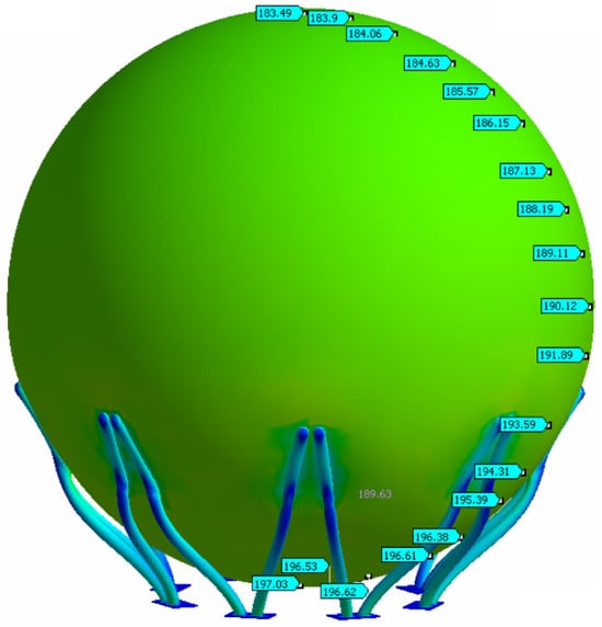
Figure 1.
Distribution of values of the equivalent stress (σe = 197.03 N/mm2) of the spherical tank using the FEM model.
The continuous structure of the spherical tank is divided into a mesh of smaller, simpler elements (e.g., triangular or quadrilateral shell elements, or even 3D solid elements for thicker sections or complex geometries like support connections). The material properties of the steel used for the tank (e.g., Young’s modulus, Poisson’s Ratio, yield strength) are defined and assigned to these elements [7]. The tank supports are modeled by defining appropriate boundary conditions that restrict movement in certain directions. Different support configurations will influence the stress and deformation patterns. Various loads acting on the tank are applied to the model. This primarily includes the internal pressure exerted by the stored fluid, which is a critical design factor for pressure vessels. Other loads, such as hydrostatic pressure (if the tank is partially filled), self-weight, and potentially external loads like wind or seismic forces (depending on the scope of the study and the tank’s location), can also be considered. The FEM software uses numerical algorithms to solve the system of algebraic equations derived from the principles of structural mechanics and the defined boundary conditions and loads [8]. These equations relate the displacements at the nodes of the elements to the applied forces. Once the displacements are calculated, the software can determine the deformation within each element using the element’s shape functions [9,10,11]. From the deformation, the stress distribution within the tank can be calculated using the material’s constitutive laws. Spherical shapes are relatively straightforward for the FEM to model accurately, compared to analytical methods that may require significant simplifications. The FEM provides a comprehensive picture of the stress and deformation distribution throughout the tank structure, including areas of stress concentration that might be difficult to predict using analytical formulas alone (e.g., around support connections, nozzles, or welds). Numerical simulation facilitates the exploration of different loading scenarios, material properties, and design modifications without the need for expensive and time-consuming physical prototypes. For example, the FEM can simulate the tank under different filling levels or with different support configurations. FEM software typically offers powerful visualization tools that depict the stress and deformation patterns through color-coded diagrams and animations, providing valuable insight into the structural behavior of the tank. Numerical simulation using the FEM can provide theoretical predictions of stresses and deformations in a spherical tank under specific conditions. Experimental verification plays a crucial role in validating the numerical model. Through comparing the results obtained from the FEM simulation (e.g., stress values at specific points, overall deformation patterns) with experimental measurements performed on a physical spherical tank (either in a scaled model or a full-scale tank), the accuracy and reliability of the numerical model can be assessed. Discrepancies between numerical and experimental results can highlight limitations in the FEM model, such as oversimplifications in geometry, material properties, boundary conditions, or loading [12]. This can lead to refinement of the numerical model to improve its accuracy. A well-validated FEM model can be used with greater confidence to predict the structural behavior of similar spherical tanks under different operating conditions or design modifications, reducing the need for extensive physical testing in the future [13].
Before the widespread use of numerical methods like the finite element method (FEM), the analysis of stress and strain in structures—including pressure vessels like spherical tanks—relied on classical analytical and semi-analytical approaches. These methods are primarily based on the principles of elasticity, solid mechanics, and the theory of plates and shells. The research in this manuscript marks a transition from theoretical, simplified analytical solutions to a powerful, practical, and highly accurate numerical approach. While classical methods provide a foundational understanding for simple designs, FEM enables the comprehensive, realistic, and detailed analysis required for the modern, safe, and efficient engineering design of complex pressure vessels.
The finite element method (FEM) is a widely used and indispensable tool for the design, analysis, and integrity assessment of spherical tanks in various industries, particularly in the petrochemical, oil and gas, and chemical processing industries. Recent studies and industrial case studies have highlighted its crucial role in understanding stress distribution, predicting failure, and optimizing design. In an industrial case study, the Dynaflow Research Group (DRG) conducted a re-evaluation of two 15 m diameter spherical tanks, originally designed in the 1960s for butane storage, for a new liquid medium with 50% higher density. ODAN-DETECH Group Inc. used the IDEA StatiCa 8.0 software, which employs the finite element method (FEM), to design the anchorage of a generic propane/butane storage sphere in a high seismic activity area (a case study mentioned by IDEA StatiCa 8.0 UK, likely published around 2017). The project involved calculating loads (dead, live, wind, seismic) with and without liquid, code compliance (AISC ASD), and Euler buckling assessment. This demonstrated the application of the finite element method (FEM) in optimizing support systems and anchor design under demanding environmental conditions. The exceptional novelty of the research study lies in its comprehensive and integrated approach to design validation, particularly for spherical tanks in the petrochemical industry, while addressing the challenges of stress concentration at support points and connections. Spherical tanks, while offering optimal stress distribution for internal pressure, are susceptible to localized high stresses at their supporting structures. The study’s focus on these specific critical areas and the experimental validation of numerical predictions in these zones significantly contributes to the practical design and safety of such tanks. Essentially, the novelty of this study lies not only in the use of advanced simulation techniques but also in the systematic and verified application of these techniques to a complex, real-world engineering problem, thereby enhancing the reliability and safety of critical petrochemical infrastructure. The following are reference standards for the design, analysis, and integrity assessment of spherical tanks in various industries, particularly in the petrochemical, oil and gas, and chemical processing industries.
- Relevant standards and practices for stress and deformation analysis
These standards provide guidelines on methodologies and considerations for performing numerical simulations and stress and deformation analyses:
- 1.
- ASME BPVC, Section II: Materials: Provides specifications for materials used in the construction of pressure vessels, including their mechanical properties, which are essential for accurate numerical modeling [14].
- 2.
- ASME BPVC, Section V: Nondestructive Examination: Details methods for non-destructive testing (NDT) to verify the absence of defects and ensure structural integrity, which can be used to validate simulated results against real-world inspections [14].
- 3.
- ASME BPVC, Section IX: Welding, Brazing, and Fusing Qualifications: Specifies requirements for welding procedures and welder qualifications, crucial for reliable fabrication and for considering welding effects in simulations [14].
- 4.
- API 520: Sizing, Selection, and Installation of Pressure-relieving Devices in Refineries. These standards are critical for ensuring safe operation and for defining the pressure limits the tank must withstand, directly impacting the design loads for stress analysis [15].
- 5.
- NFPA 58: Liquefied Petroleum Gas Code: Relevant if the spherical tank stores LPG, as it provides specific safety requirements for such installations, which can influence design considerations like fire protection and spacing. API 2510: Design and Construction of LPG Installations: Provides guidelines for the design and construction of LPG facilities, including spherical tanks [16].
- 6.
- ISO 16528: Boilers and Pressure Vessels—Performance requirements for design and manufacture: This international standard provides a general framework for the design and manufacture of pressure equipment, which can be used to ensure overall compliance and quality [17].
- Standards for experimental verification
Although there is no single “standard of experimental verification” for all pressure vessels, for experimental verification, the following general principles and specific tests are often referred to:
- 1.
- Hydrostatic testing: This is a common and critical experimental test prescribed by most pressure vessel codes (e.g., ASME, EN 13445). It involves filling the vessel with water and pressurizing it to a specific pressure (generally significantly higher than the design pressure) to prove its structural integrity and leak-tightness. Deformation measurements during this test can be compared with numerical predictions.
- 2.
- Strain gauge measurements: Applying strain gauges during hydrostatic testing or during operation can provide real-time strain and stress data for direct comparison with numerical simulation results.
- 3.
- Non-destructive testing (NDT) methods (e.g., ultrasonic testing, radiographic testing, magnetic particle testing, liquid penetrant testing): While primarily intended for defect detection, NDT results can indirectly validate numerical models by confirming the absence of significant flaws that would alter stress distribution.
- 4.
- Material testing standards (e.g., ASTM, EN standards for tensile, yield, impact, fatigue properties): Experimental verification of the material properties used in the numerical model is fundamental to ensuring the accuracy of the simulation. This includes standard tests for determining tensile strength, yield strength, elongation, Charpy impact toughness, and fatigue behavior.
- 5.
- Proof testing: This involves applying a controlled load to a structure to demonstrate its ability to withstand the design loads without failure. While similar to hydrostatic testing for pressure vessels, it can also be applied to other loading scenarios or structural components.
While the existing literature provides foundational knowledge on membrane stresses in idealized spherical tanks, it does not offer the detailed, localized stress analysis necessary for safe and efficient design. This study fills that gap by demonstrating how the finite element method (FEM) can be utilized as a powerful tool for modeling complex geometries and loading conditions, thereby providing a more accurate and complete understanding of the mechanical behavior of real-world spherical storage tanks.
2. Mathematical Modeling
The study applies the finite element method (FEM) to analyze the stress and strain in a spherical fluid storage tank. The constitutive material parameters are fundamental for defining its behavior under load. Since most spherical tanks are constructed from steel alloys, the material is modeled as a linearly elastic, isotropic, and homogeneous material for the initial analysis. This assumes that the material properties are consistent in all directions and that stress is directly proportional to strain, following Hooke’s Law. The key constitutive parameters needed for this type of analysis are the following: Young’s modulus (E), which represents the material’s stiffness—the ratio of stress to strain in the elastic region. For steel alloys commonly used in pressure vessels, such as SA-537M CL.2, SA-106 Gr. B, or various stainless steels, a typical value is approximately 200 GPa (or 29.0 × 10⁶ psi). The other parameter is Poisson’s Ratio (ν), a dimensionless value that describes the material’s lateral strain in response to axial strain. When a material is compressed in one direction, it expands in the other two. Poisson’s Ratio is the ratio of this transverse strain to the axial strain. For steels, the value is typically around 0.3.
By highlighting specific functions and mathematical concepts, the theoretical foundation upon which the numerical simulation is built can be clearly articulated. As spherical tanks are thin-walled pressure vessels, shell theory is fundamental. Key functions include meridional force, circumferential (hoop) force, shear forces, bending moments, and constitutive laws (material properties) that define the relationship between stress and strain for the tank material (e.g., steel). This is crucial for converting calculated deformations into stresses and vice versa.
Load functions and boundary conditions define the external and internal forces acting on the tank and the constraints on its movement; internal pressure is the primary load for pressure vessels. External loads include gravity/self-weight, wind load, seismic load, and thermal loads if temperature variations are significant, using functions describing thermal expansion/contraction and the resulting stresses. Support reactions are functions that describe the forces and moments exerted by the tank supports (e.g., legs or skirts), which act as boundary conditions. These may include stiffness functions, if the supports are flexible. Displacement and deformation functions describe how the tank deforms under load and how these deformations relate to stresses. Key functions are displacement fields that describe the movement of points on the spherical shell in the radial, meridional, and circumferential directions. Geometric equations that relate these displacements to normal and shear strains within the shell material for thin shells often involve derivatives of the displacement functions concerning curvilinear coordinates.
The state of stress in the shell elements in the form of a rotating surface can be determined by the equilibrium equations for the shell elements. The forces acting on an element that is part of a shell in the form of a rotating surface are shown in Figure 2. The element is defined by two parallel circles, with radii and , and two adjacent meridians determined by angles θ and θ + dθ. The position of the element belonging to the shell in the form of a rotating surface for a spherical tank is shown in Figure 2a, as well as the components of the external surface load X, Y, and Z. The internal forces acting on this element are shown in Figure 2b [18,19,20]. The tank is considered to operate in moderate climatic conditions, such that the influence of temperature can be neglected.
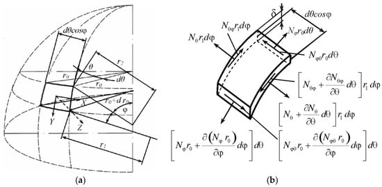
Figure 2.
(a) Position of a shell in the shape of a surface of revolution. (b) Internal forces in the element of the shell in the form of a rotating surface.
The Finite Element (FE) model of a spherical tank is a discretized representation of the actual structure. It begins with creating the geometry, which is then divided into a finite number of small, interconnected elements that form the mesh. For a spherical tank, common element types include shell elements—2D elements used to model the thin-walled spherical shell. These are computationally efficient and capture both the bending and membrane stresses of the tank wall. Boundary conditions define how the model interacts with its environment, typically involving fixed supports where the base of the legs is anchored to the ground. Loads applied to the model can include internal pressure from the stored fluid, gravity (the weight of the tank and its contents), and wind or seismic loads, which are applied as pressure or inertial forces, respectively. Simulating contact points at structural interfaces is critical, especially where parts of the structure can move relative to each other but cannot pass through one another. In a spherical tank analysis, this is most relevant at the interfaces between components like the tank shell and the support structure, as well as at bolted or welded joints. The introduction of structural materials is a fundamental part of any Finite Element Analysis (FEA). The choice of material model depends on the intended analysis. For a spherical tank, materials are defined by their material type (steel is a common choice) and their elastic properties. For standard stress analysis, the material is often assumed to be linear-elastic and isotropic. Key parameters are Young’s modulus (E), which measures material stiffness, and Poisson’s Ratio (ν), which describes lateral strain in response to axial strain. For non-linear analysis, plastic properties like yield strength are also required. Each part of the model (e.g., the spherical shell, supports) is assigned its specific material properties. The analysis software then uses these properties to calculate how the material deforms and what stresses develop under the applied loads.
This equation represents the equilibrium of a small element of the spherical tank in the meridional direction:
- —the contribution of the change in the meridional membrane force to the equilibrium in the meridional direction,
- —the meridional membrane force per unit length in the spherical shell,
- —the meridional angle, measured from the pole of the sphere,
- —the rate of change in the meridional membrane force with respect to the meridional angle,
- —the radius of curvature with respect to the meridional direction,
- —the contribution of the in-plane shear membrane force to the equilibrium in the meridional direction,
- ()—the in-plane shear membrane force per unit length in the spherical shell. This force acts in the plane of the shell, with one component along the meridional direction and the other along the circumferential direction,
- s—the circumferential angle (or longitudinal angle),
- —a component of the shear force acting in the meridional direction due to curvature,
- —the rate of change in the circumferential component of the in-plane shear membrane force with respect to the circumferential angle. This term represents the contribution of the change in the in-plane shear membrane force to the equilibrium in the meridional direction,
- —the other radius of curvature that relates to the circumferential direction. For a sphere, = ,
- —the external force per unit area acting on the spherical shell in the meridional direction.
The equation of the change in internal forces (shear and normal) along the meridional and circumferential directions with external loading acting on the element is as follows:
- —the shear force acting on a surface element of a spherical tank,
- —the rate of change in the resultant shear force with respect to the circumferential angle,
- —the radius of curvature of the spherical tank in the meridional direction,
- —the normal force acting in the circumferential direction on the surface element,
- = r\sin—the radius of the parallel circle at a given meridional angle,
- —normal force acting in the meridional direction on the surface element,
- —the rate of change in the product of the meridional normal resultant (Nφ) and the radius of the parallel circle (Rsinφ) with respect to the meridional angle (φ),
- —the external force per unit area acting on the surface of the spherical tank. The direction of this force is determined based on the overall equilibrium equation,
- —a surface element on the surface of the spherical tank in spherical coordinates.
The membrane equilibrium equation (Figure 3) in the radial direction for a thin-walled spherical tank subjected to internal or external pressure is as follows:
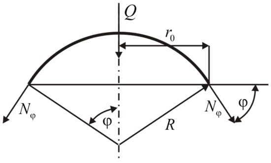
Figure 3.
Equilibrium of the shell section.
- —the resultant circumferential membrane force. It is a force per unit length acting in the tangential direction along the parallel circle of the sphere,
- —the radius of curvature in the circumferential direction. For a perfect sphere, is equal to the constant radius of the sphere (which is denoted as and therefore, = = .
Total vertical component of the meridional membrane forces is as follows:
- —circumference of the parallel circle on the sphere at a meridional angle φ.
Equation (4) represents the external vertical force acting on the portion of the spherical tank above (or below) the parallel circle at an angle φ [21,22]. This force can be a result of the weight of the fluid in the tank up to that level, the weight of the tank material itself, or other external loads. Altogether, it expresses the equilibrium of vertical forces for the part of the spherical tank bounded by the apex (or bottom) and the parallel circle at an angle φ. It states that the total vertical component of the internal meridional membrane forces must balance the external vertical force (Q) (Figure 4) [23,24,25].
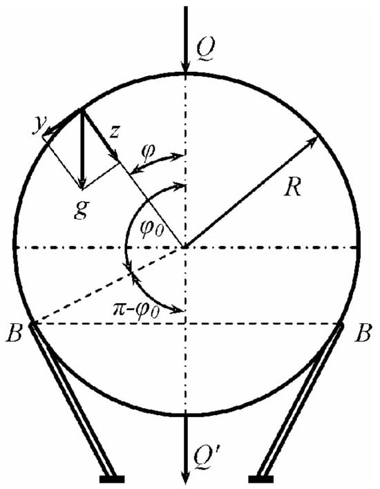
Figure 4.
Membrane forces (Nφ) at a specific angle (φ) if the external vertical load (Q) is known.
- —the resultant meridional membrane force, which represents the force per unit length acting tangentially along the meridian,
- —acceleration due to gravity,
- —radius of the spherical tank,
- —meridional angle (φ), which is usually measured from the top or bottom pole of the sphere,
- —this term in the denominator indicates how the meridional force varies with the angle φ.
The negative sign in front suggests that the meridional force is compressive. This makes sense because the weight of the material above a certain part of the sphere will tend to compress the material along the meridian to support it.
Formula (5) states that the meridional membrane force at a given meridional angle φ is proportional to the weight per unit area of the tank material (implicitly through g) and the density of the material, which is assumed constant and built in. Heavier material will result in higher internal forces. The membrane force is proportional to the tank radius (R). Larger tanks will generally experience higher membrane forces due to the increased material weight. At the top of the tank (φ = 0), cosφ = 1, and so . The compressive force is finite at the top and is inversely proportional to 1+cosφ. It is shown how the meridional force changes with the angle (φ). As the angle φ increases toward the supports (which would be at some angle φ < π/2 if the tank were supported around a circular base), the value of cosφ decreases, and 1 + cosφ also decreases, leading to an increase in the magnitude of the meridional pressure force (). If we were to theoretically consider the equator (φ = π/2), then cosφ = 0 and = −gR. As φ approaches π (the lower pole), cosφ approaches −1, and the denominator 1+cosφ approaches 0. This suggests a theoretical singularity in the lower hemisphere if the weight of the entire sphere is taken into account and if there are no supports to directly take the load. However, in a real supported tank, this region would not be part of the “above the supports” consideration in the same way.
Formula (5) specifically gives the meridional component of the internal membrane forces that are necessary to maintain equilibrium with the weight of the portion of the spherical tank material located above the parallelogram defined by the angle φ. As we move down the tank (increasing φ), this portion becomes larger and heavier, requiring greater internal compressive forces along the meridian to support it. To obtain a complete picture of the internal forces, one should also determine the circumferential (rim) membrane force () under this loading condition. The analysis of a spherical shell under its own weight usually involves solving the membrane equilibrium equations in both the meridional and circumferential directions. The following formula provides a distribution of the meridional membrane compression force in a spherical tank due to the weight of the material over a given latitude, characterized by the angle φ. The force increases as we move toward the supports (increasing φ), reflecting the need to support more weight.
- —the resultant of the circumferential (or hoop) membrane force. It is the force per unit length acting tangentially along a parallel circle at an angle φ,
- g—acceleration due to gravity,
- R—radius of the spherical reservoir,
- φ—meridional angle, usually measured from the top pole,
- 1/(1 + cosφ)—this term is related to the meridional force distribution we saw earlier.
Formula (6) shows that the circumferential membrane force at a given angle φ is affected by two parts:
- −gRcosφ—this part suggests the contribution related to the vertical component of the meridional forces and the geometry of the sphere,
- (cosφ)—denotes how the angle affects this contribution. At the top (φ = 0), cosφ = 1, which leads to a compressive contribution. As φ increases, cosφ decreases, reducing this compression effect and potentially leading to tension at larger angles,
- gR/(1 + cosφ)—this part is directly related to the meridional force (). Since = −gR/(1 + cosφ), the term gR/(1 + cosφ) can be written as −. It represents the contribution of the meridional tension (or compression) acting around the parallel circle, which has a radial component that must be balanced by the hoop stress.
The combination of these two terms determines whether the circumferential force () is tensile or compressive at a given angle φ.
The circumferential force at the top is compressive and equal to the meridional force.
As φ increases, the behavior of becomes more complex as cosφ decreases. The first term (−gRcosφ) becomes less compressive (or even tensile), while the second term (+gR 1/(1 + cosφ); which is ) becomes more compressive (since ) is compressive and its magnitude increases.
Around the supports (at some angle φ < π/2), the value of will depend on the specific angle of the support. It is possible for to change sign (from compressive to tensile) depending on the geometry and self-weight distribution.
The force due to the greater self-weight of the tank above the supports emphasizes that the internal forces, both and , arise from the need to support the weight of the tank material above the level considered (defined by φ). As we move down the tank, the amount of material above increases, resulting in a greater load that must be carried by the internal membrane forces [26,27,28]. The specific shape of reflects how this weight is distributed and resisted in the circumferential direction, taking into account the meridional forces and the curvature of the shell.
In short, the formula for gives the force distribution of the circumferential membrane in a spherical tank under its own weight above the supports. Its shape indicates a balance between geometric effects and the contribution of meridional forces, resulting in a stress state that varies with the meridional angle φ. Understanding both and is crucial for the structural analysis and design of spherical tanks [29].
- p = −Z—the total pressure (p) is equal to the negative value of the external load per unit area (Z). In the context of a pressure vessel, the negative sign usually means that Z represents the internal pressure acting externally on an element of the vessel’s surface. Therefore, p is the internal pressure,
- γR (1 − cosφ)—the hydrostatic pressure in the fluid at a depth corresponding to the meridian angle (φ),
- γ—the specific gravity of the liquid,
- R—the radius of the spherical tank,
- (1 − cosφ)—a factor that determines the depth of the liquid depending on the angle (φ), usually measured from the top of the tank. When φ = 0 (top), 1 − cos 0 = 1 − 1 = 0, and the hydrostatic pressure is zero. As φ increases, cosφ decreases and 1 − cosφ increases, which means that the depth and therefore the hydrostatic pressure increase. At the bottom of the tank (φ = π), 1 − cosπ = 1 − (−1) = 2, such that the hydrostatic pressure is maximum and is equal to 2γR (if the tank is full to the bottom),
- —the uniform pressure that is superimposed (added) to the hydrostatic pressure. “Uniform” means that this pressure is constant over the entire surface of the tank and does not depend on the meridian angle (φ). This pressure may come from the gas above the liquid in the tank or from some other external uniform load.
Adding these components gives the total internal pressure (p) at any point in the spherical tank defined by the angle φ.
In short, the formula p = −Z = γR(1 − cosφ) + ) indicates that the total internal pressure on a spherical tank is composed of two parts:
The hydrostatic pressure of the liquid, which varies with depth (and therefore with the angle φ) and the uniform pressure, which is constant over the entire internal surface of the tank. Formula (8) is important for analyzing the stresses and strains in the walls of a spherical tank under the action of an internal pressure that is not only hydrostatic but also has a constant component. Using this formula for p (or −Z), the equilibrium equations can be further solved.
In the context of a spherical tank, the formula refers to the bearing capacity or stability analysis of a spherical tank foundation.
- γ—the unit weight of the soil supporting the spherical tank,
- R—the radius of the spherical tank,
- φ—the angle of internal friction of the soil under the tank foundation,
- —the gas pressure inside the spherical tank,
- —the shear strength properties of the soil and how they contribute to the bearing capacity under the load imposed by the tank,
- —the internal gas pressure of the tank and its radius. The factor 2 directly multiplied by the radius suggests that this could be related to the increasing force or stress distribution caused by this internal pressure acting on the tank foundation or supports.
Hydrostatic pressure for a spherical tank is primarily relevant in two ways:
The pressure exerted by any liquid contents within the tank: If a spherical tank is filled with liquid, the pressure at any point within the liquid (and therefore on the inside surface of the tank) will depend on the depth of the liquid at that point and the density of the liquid. This internal hydrostatic pressure acts outwardly on the tank walls [30,31].
Pore water pressure in the supporting soil: If the foundation of a spherical tank is below the water table, the soil pores will be filled with water, exerting hydrostatic pressure. As mentioned earlier, this pore water pressure affects the effective stress in the soil, which in turn affects the bearing capacity.
Internal gas pressure refers to the pressure exerted by any gas contained within the spherical tank.
The gas pressure inside the tank will exert an outward force on the tank walls. This force will be transmitted through the tank structure to its supports and then to the foundation. The term in the formula indicates that this internal gas pressure contributes to the total bearing demand on the soil. A higher internal gas pressure would likely increase the foundation load.
Formula (8) can be used to determine a factor that, when multiplied by other bearing capacity terms (such as cohesion and fill), represents the ultimate bearing capacity of the soil beneath the spherical tank [32]. The inclusion of the term internal gas pressure indicates that the force or stress caused by this pressure is taken into account in the stability analysis.
Hydrostatic pressure can be relevant both internally (from the liquid content) and externally (as the pressure of water in the soil pores), and only the effects of internal gas pressure are directly included in the given in Formula (10).
The internal gas pressure () inside the spherical tank exerts an external force, increasing the load transmitted to the foundation, which is reflected in the term .
- —the hoop force or circumferential normal force in a structural element at a given angle φ. It is a measure of the tension or compression acting along the circumference,
- —the specific gravity (weight per unit volume) of the fluid exerting hydrostatic pressure. If the structure was submerged in water, γ would be the specific gravity of the water,
- —the radius of curvature of the structural element (assuming it is curved, such as an arch or cylindrical shell),
- φ—an angular coordinate that defines the location on a structural element where the internal force is calculated. It is usually measured from a reference point, often a crown or support,
- ⌊⌋—the expression enclosed in the floor function symbols (although they may be parentheses, depending on the context) represents the distribution of the hoop force due to hydrostatic pressure as a function of the angle φ. The trigonometric functions (cosφ) indicate how the depth and hence the hydrostatic pressure vary with the angle. The term 1 + cosφ in the denominator suggests that the angle φ is measured from above or below, where cosφ = − 1 may be a special case,
- —the internal gas pressure acting above the support. This pressure is uniform in the area it acts on,
- t—the contribution of the internal gas pressure to the hoop force. It is the direct tensile force caused by the internal pressure acting on the curved surface. It denotes the force per unit length (the hoop force ).
The formula essentially calculates the total hoop force () at a specific angular location (φ) in the structure by adding two contributions:
- —the hoop force resulting from the hydrostatic pressure exerted by the fluid. The magnitude of this force depends on the specific gravity of the fluid (γ), the geometry of the structure (radius R), and the angular position (φ). A complex trigonometric function captures the uneven distribution of hydrostatic pressure with depth [33].
In simpler terms, the formula determines how much volumetric tension or compression exists at various points in a curved structure (such as a submerged arch or a pressurized tank with a specific geometry) due to the combined effects of the weight of the fluid pressing on it and the pressure of any gas trapped inside above the water level.
Formula (10) directly calculates the force per unit length (the hoop force).
Key differences and similarities compared to the previous formula are as follows:
- —the distribution of the meridional force due to hydrostatic pressure as a function of the angle φ. The form of this expression reflects how hydrostatic pressure and geometry contribute to the forces in the meridional direction. 1 − cosφ in the denominator suggests that the forces could become very large near the bottom (if φ is measured from the top),
- —the contribution of internal gas pressure to the meridional force. Similarly to the hoop force, it adds a tension component due to internal pressure.
Formula (10) calculates the total meridional normal force () at a specific angular location (φ) in the structure, taking into account the combined effects of the hydrostatic pressure from the fluid below the support and the pressure of any gas trapped inside below the support.
The change in the trigonometric term, especially the denominator 1 − cosφ, strongly suggests a different physical scenario compared to the first formula. This implies the following:
A submerged structure where the angle φ is measured from the bottom. In this case, for φ = 0 (bottom only), cosφ = 1 and the term can become very large, indicating high meridional forces at the lowest point due to hydrostatic pressure.
In short, Formula (10) provides the meridional (or similar longitudinal) internal force in a curved structure that is subjected to hydrostatic pressure from below and internal gas pressure under the support.
The mathematical form indicates that the distribution of this force with angle φ is different from the hoop force and reflects the specific way in which these pressures act on the geometry in the meridional direction.
To gain a more precise understanding, knowledge of the exact geometry of the structure and the definition of angle φ is helpful.
3. Finite Element Simulation and Experimental Verification
Based on common practice in the field of spherical tank and pressure vessel analysis, some of the most frequently used FEA software programs are the following:
- ANSYS 2020 R1: A widely used commercial finite element method software program with comprehensive capabilities for structural, thermal, and fluid–structure interaction analysis. Many studies on pressure vessels and spherical tanks utilize ANSYS, which was also applied in this study.
- ABAQUS 2021: Another prominent commercial FEA program, known for its advanced material models and ability to handle complex non-linear simulations.
- COMSOL Multiphysics 6.0: A multiphysics simulation program that can couple various physical phenomena, which is useful in situations involving thermal and pressure loads on spherical tanks.
- Nastran 2021.4 (MSC Nastran, Siemens PLM NX Nastran): Originally developed for NASA, it is powerful FEA software used for structural analysis, particularly in the aerospace and automotive industries, but can also be applied to pressure vessels.
- RFEM 5: A 3D finite element analysis program used for structural design and dimensioning, including spherical storage tanks.
- The mesh refinement process begins with a coarse mesh to run the simulation and obtain initial results, as well as to identify areas of stress concentration. Mesh refinement involves creating a new mesh with a smaller element size, focusing on critical areas. Rerunning the analysis solves the problem with the refined mesh. By comparing the results, it is verified whether the key output parameters have changed significantly. The process is repeated until the change in output parameters is below the defined convergence criteria. The mesh that satisfies this criterion is the one that should be used for the final analysis. By following this systematic and well-documented procedure, the accuracy of the finite element method (FEM) results can be confidently confirmed, and the conclusions about stress and deformation in the spherical tank are ensured to be reliable.
The finite element method was used to calculate a spherical tank with a volume of V = 1000 m3, an outer diameter of D = 12,500 mm, and a wall thickness of δ = 30 mm. The spherical tank is made of steel segments with a yield stress of .
The working pressure in the tank is = 16.7 MPa. Experimental testing was performed with water (γv = 1000 N/m3) instead of a propane–butane gas mixture. Using expressions (6)–(10) and the expressions for stresses:
The corresponding values of forces and stresses for different angles are obtained. The total value of stress is calculated by adding the components of self-weight and internal pressure. The obtained values are shown in Table 1 and Figure 5.

Table 1.
Stresses due to internal pressure and self-weight.
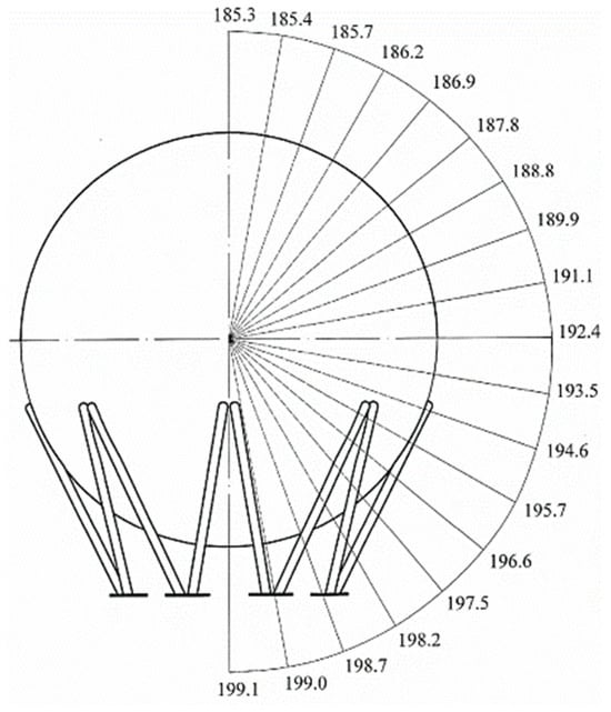
Figure 5.
Visualization of stress concentration in a spherical tank.
The continuous geometry of a spherical tank is divided into a finite number of discrete elements. For a spherical tank, common element types are “shell elements” (e.g., triangular or quadrilateral) or “solid elements” (e.g., tetrahedral or hexahedral). Shell elements are often used because the tank’s wall thickness is small compared to its radius, and they are computationally more efficient. Each element is defined by a set of points called “nodes”. Nodes are the points where elements are connected and where degrees of freedom (such as displacement and rotation) are calculated. The number of elements and nodes determines the “mesh density.” A finer mesh (more, smaller elements) provides a more accurate result but requires more computational resources. The study considered the need to find a balance between accuracy and computational cost. Areas with high stress concentration, such as the connections between the tank and its supports, often require a finer mesh to accurately capture rapid stress changes. For the purpose of creating the FEM model, a 10-node tetrahedral element was selected. The 3D model of the spherical tank was formed by synthesizing the 3D models of all structural parts. The model represents a continuum of discretized pieces (45,124 nodes, 25,016 elements). The equivalent stress field is shown in Figure 1. The distribution of equivalent stresses from the FEM analysis corresponds to the stress distribution obtained by analytical calculation.
The highest stress values were obtained at the support points of the spherical tank (Figure 6).
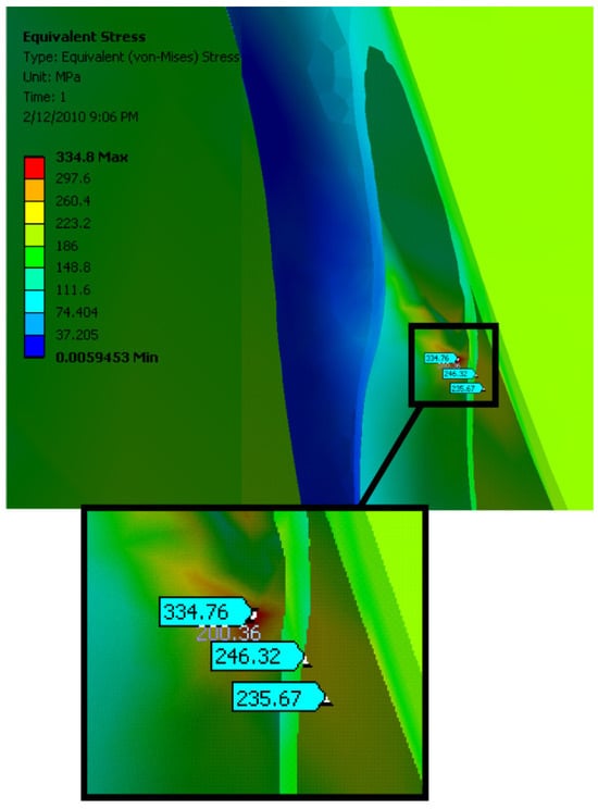
Figure 6.
Stress analysis of a spherical tank with details on the load transfer points to the supporting structure.
Figure 5 highlights a key purpose of this type of analysis-identifying areas where stress is highest or concentrated.
Figure 6 shows where the highest stress is concentrated on the spherical storage tank, specifically at the points where it connects to its supports.
The deformations of the spherical tank are shown in Figure 7. Since the FEM analysis identified hazards in the proposed design, experimental verification was required in order to be absolutely certain that the plastic deformations in the supports would not cause structural failure. These values are higher than the yield stress and may cause deformation of the tank supports. Since the area of this high stress concentration is very small, it was concluded that the overall strength of the supports will not deteriorate over time due to the accumulation of plastic deformation.
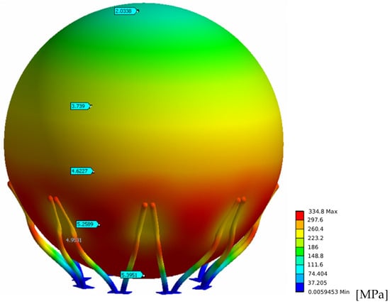
Figure 7.
Buckling and collapse of a spherical storage tank.
Figure 7 shows the simulated collapse of a spherical tank, structural damage, and significant plastic deformation.
Experimental testing of the spherical tank was performed to verify the results of the analytical and FEM models. For safety reasons, the experiment was performed with water instead of a propane–butane gas mixture. Stress measurements were performed at seven measurement points using the HBM UPM 100 measuring equipment. The arrangement of the measurement points is shown in Figure 8. This type of strain gauge setup facilitates measurement and does not require knowledge of the direction of the principal stresses.
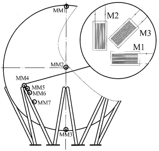
Figure 8.
Arrangement of data collection points.
The experimental process for testing the stress and strain of a spherical tank involves a combination of analytical and numerical methods with physical testing to validate the results. The goal is to understand the structural behavior of the tank under various loading conditions, specifically internal pressure.
The experimental setup and finite element analysis (FEA) for a spherical tank would involve a combination of physical testing and numerical simulation. For the tank model and scaling, the study uses a full-size physical model of a spherical tank. The tank is made of a material like carbon steel, which is consistent with industrial applications. The spherical tank is supported in a way that accurately represents its real-world installation. Common support conditions for spherical tanks are point supports. The tank is supported on several radially arranged columns. This is a common and critical area of study, as it is a zone of high stress concentration. The base of the supports is properly constrained in the experimental setup to represent “fixed” or “pinned” foundation conditions. The loads applied to the tank in the experiment simulate the expected operating conditions. The measurement settings include strain measurement. Strain gauges are the main instruments used to measure the surface deformation of the tank. They are strategically placed at various points to record strain in different directions. Displacement measurements were performed using linear variable differential transformers (LVDT) at specific points. Strain and displacement data from the sensors are collected using a data acquisition system (DAQ). The DAQ records measurements at regular intervals as the load is gradually applied.
Pressure transducers are calibrated against a known pressure standard. This process ensures that the electrical output of the transducer accurately corresponds to the applied pressure. Accuracy is expressed as a percentage of the full-scale output. The typical accuracy of the high-quality pressure transducer used in this study is in the range of ±0.1% to ±0.5% of full scale. The data acquisition system is calibrated to ensure the correct conversion of analog signals (from strain gauges and pressure transducers) to digital data. The accuracy of the system depends on the resolution of its analog-to-digital converter and the quality of the signal conditioning.
The system’s accuracy is determined by the manufacturer and is a combination of factors such as linearity, noise, and gain accuracy. A high-resolution system (e.g., 24-bit) was used to record small changes in resistance from the strain gauges with high precision.
In summary, the accuracy of the overall experiment does not depend solely on the specifications of an individual instrument but on the careful consideration of the entire measurement chain, from the sensor itself to the data acquisition system and analysis software. The use of multiple measurement points, redundant sensors, and established calibration procedures was essential to ensure the reliability and credibility of the experimental results.
Figure 8 shows a diagram of the physical setup with multiple sensors or probes.
Figure 9 clarifies that the gauges are installed on the object and are part of the test.
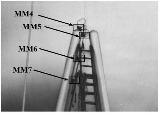
Figure 9.
A view of the strain gauges installed on the test object, specifically at locations MM4 to MM7.
4. Results and Discussion
Based on the research conducted, key consistent data for the stress and strain analysis of spherical tanks have been obtained:
The finding is that the areas where the spherical tank connects to its supports (legs, columns, etc.) experience the highest stress levels. The equivalent stress in these regions can approach or even exceed the material’s yield strength, making them critical points for design and analysis.
The accuracy of the finite element method results is consistently shown to be highly dependent on the quality of the finite element mesh, as well as on the proper definition of loads and boundary conditions. Poorly defined meshes, especially in areas of geometric complexity such as supports, can lead to inaccurate or unreliable results.
A key theme in this study is the need to validate the results of the finite element method (FEM) against experimental data (e.g., from strain gauges) or traditional analytical calculations. Although FEM is a powerful tool, it is not infallible, and comparison with real-world or theoretical data is crucial for ensuring accuracy and reliability, especially in critical areas.
Adopting the standard ASME VIII-2 analysis and design method, in [34], ANSYS 2020 R1 finite element software was used to analyze and calculate a 6000 m3 spherical propane tank, which is crucial for storing propane as a raw material for hydrogen production in the hydrogen energy sector. The study considers the establishment of a finite element model of the spherical tank, the structural optimization of the connection between the support column and the spherical shell, the stability of the support column, local fracture, and other key issues. A secondary development of the ANSYS 2020 R1 software was carried out, with a subroutine written to calculate the algebraic sum of the three main stresses, and the calculation results were verified. The study shows that the maximum stress occurs at the junction between the support column cover and the spherical shell; reducing the thickness of the support column cover can effectively decrease the values of local stress.
Studies consistently analyze the effects of various loads on the stress and strain state of the tank. The primary failure modes considered in the analysis of spherical pressure vessels are consistently identified as yielding and buckling. Stress analysis is performed to evaluate yielding, while stability analysis is conducted to assess the risk of buckling, especially on the outer shell of double-walled tanks exposed to compressive forces.
Calculations of the stability of the spherical tank support structure under hydrostatic test loads have shown that the first yield boundary occurs at the junction between the top support column and the spherical shell [35,36]. It is suggested that the stability of the support column should not be calculated exclusively based on steel structure standards, but also that the influence of local buckling should be taken into account. This research is significant for the hydrogen energy industry, which plays a key role in space engineering, as propane storage tanks are essential for storing raw materials used in hydrogen production.
The study emphasizes the importance of material properties, such as Young’s modulus of elasticity, yield strength, and Poisson’s Ratio, in determining the tank’s stress response. FEM is a valuable tool for design optimization by simulating the effects of different materials and structural configurations to improve safety, reduce weight, and ensure integrity.
Table 2 gives the comparative stress values for a working pressure of 1.67 MPa obtained at characteristic points: analytically, by the FEM model, and experimentally.
Table 2.
Comparative stress values obtained analytically, by the FEM model, and experimentally.
Table 3 shows the deviation of the equivalent stresses obtained analytically and by the FEM model.
Table 3.
Percentage deviation of equivalent stress.
The experimentally obtained stress values for some measurement points are higher than the analytical or FEM calculated stress values at the point shown in Table 2, while for these two tables they have a lower value. The discrepancy requires experimental verification to ensure that the proposed design will meet all safety requirements. The equivalent stress values for the test pressure of 2.5 MPa are shown in Table 4, and the deviations from the results obtained analytically and using the FEM model in relation to the results obtained experimentally are shown in Table 5.
Table 4.
Stress values for test pressure.
Table 5.
Deviation of equivalent stresses obtained analytically and by the FEM model in relation to the results obtained experimentally for the test pressure.
Implications for Practical Engineering Design
This involves the identification of high-stress areas. Unlike simplified analytical methods, FEM identifies regions of high stress concentration. These are located at geometric discontinuities, such as the connections between the spherical shell and its supporting columns, nozzles, or other attachments. Knowing these weak points allows engineers to reinforce them specifically, instead of over-designing the entire structure.
Research on spherical tanks in China began relatively late, and there is currently a clear trend toward larger sizes and higher parameters. However, the structural and strength design of large spherical tanks based on international standards is still incomplete.
Yu Yong et al. performed analytical calculations on a 4000 m3 spherical tank using finite element analysis software and conducted stress assessments based on ASME VIII-2, “Rules for Construction of Pressure Vessels”, summarizing stress analysis design methods for spherical tanks. P. Das et al. performed an elastic analysis of thick-walled spheres made of functionally graded materials (FGM) to investigate stress and displacement fields under constant internal and external pressures. This study used both analytical and numerical methods, creating accurate models and finite element models of a spherical pressure vessel with a continuously varying Young’s modulus [37,38]. It was assumed that the modulus of elasticity varied non-linearly with thickness. The authors developed analytical solutions for displacement and stress distribution in the radial direction and compared them with the results of the finite element analysis [39]. Zheng Jian et al. analyzed the mechanical properties of a 4000 m3 spherical tank using finite element analysis methods, performing a detailed analysis of weak points through stress assessment. Li Yongtai et al. used various methods to analyze stress calculations for columns and connecting rods under horizontal seismic conditions of a spherical tank structure, pointing out several issues to consider when designing a spherical tank structure, providing a reference for the stress analysis design and optimization of larger volume spherical tanks.
Design optimization using FEM enables engineers to simulate various design changes quickly and cost-effectively. They can experiment with different materials, wall thicknesses, and support structures to find the optimal balance between cost, weight, and safety. For example, FEM can show that a slight increase in thickness at a specific location, like a support attachment, is more effective than a uniform increase across the entire sphere.
Complex Loading Scenarios
FEM allows for the simulation of complex and combined loading conditions that are difficult or impossible to analyze with traditional methods. These include the following:
Hydrostatic pressure: The pressure of the stored fluid, which varies with depth.
Environmental loads: Wind and seismic forces.
External forces: Forces that can cause fluid sloshing and soil–structure interaction.
Thermal gradients: The effects of temperature differences between the tank’s interior and exterior, especially relevant for cryogenic or high-temperature storage.
Fatigue loading: Repeated cycles of pressurization and depressurization.
Implications for Safety Margins
The detailed results from FEM analysis allow for a more precise and often less conservative approach to safety margins, while maintaining or even improving overall safety. FEM enables engineers to transition from a prescriptive “design-by-formula” approach, found in some older codes, to a more sophisticated “design-by-analysis” approach. This means that instead of relying on generic safety factors, they can use a consistent set of loads, boundary conditions, and failure modes to assess the tank’s actual behavior. This can lead to lower but more accurate safety factors, resulting in material and cost savings without compromising safety.
The finite element method (FEM) is crucial for predicting various failure modes beyond simple yielding, such as buckling and fracture. By simulating these failure mechanisms, engineers can design the tank to withstand them, ensuring a robust and reliable structure. FEM can also be used to verify the adequacy of design codes and standards, such as those from ASME. It provides the means to perform a detailed stress assessment and ensure that induced stresses remain within the allowable limits defined by these standards.
Implications for Service Life
FEM analysis provides a powerful framework for predicting the service life of a spherical tank, which is critical for maintenance planning and long-term operational safety. FEM can simulate cyclic loading to predict the tank’s fatigue life, especially at points of stress concentration. By using post-processing software with the stress/strain results from FEM, engineers can estimate the number of cycles the tank can endure before fatigue failure is likely to occur. This is essential for vessels subject to frequent pressure or temperature changes.
By combining analytical calculations, the finite element method (FEM), and experimental data (e.g., from strain gauges), a comprehensive assessment of structural integrity can be performed. This approach provides a high level of confidence in the design, and repeated testing can be used to verify that the tank’s behavior remains consistent over time, justifying its service life.
Many studies focus on the general application of FEM to pressure vessels. These studies often compare FEA results with traditional analytical methods (such as ASME code calculations) and experimental data to confirm the accuracy of the numerical model. They also investigate the advantages of FEA for complex geometries and loading conditions that are difficult to analyze with simple formulas. Although this study focuses on hydrostatic pressure, many similar studies expand upon this by analyzing spherical tanks under various loads, including seismic and wind loads. A significant number of studies focus on the dynamic response of spherical tanks to earthquakes and strong winds. They analyze how these forces affect the entire structure, including fluid sloshing and stresses on supporting legs and anchoring systems.
5. Conclusions
The methodology presented in this paper—which benefits from the advantages of analytical, numerical, and experimental procedures—ensures fast design time, optimal dimensioning and most importantly, safe operating conditions.
Traditional studies only consider internal pressure. This study analyzes the effects of combined complex loads, such as seismic loads, thermal gradients, external pressures, and fatigue analysis. The innovation of the study is not in the use of the finite element method (FEM), but in the way FEM is applied. It focuses on solving a previously unsolved or poorly understood problem, design optimization, or integrating multiple complex analyses to provide a more comprehensive and accurate understanding of the behavior of a spherical tank under real-world conditions.
The conducted research revealed a high degree of correspondence between the results obtained analytically, those obtained with the FEM model, and the results of experimental testing using spherical tanks. This correspondence supports the use of analytical expressions for the dimensioning of spherical tanks. This is especially important as the basic dimensions of a spherical tank can be obtained within a short period of time during the initial design phase, without the need to perform experiments or FEM modeling.
After the initial design phase, when all the dimensions of the tank are known, a more precise FEM analysis can be carried out to identify areas of high stress concentration. In the case of the analyzed tank with a test pressure of 2.5 MPa, the equivalent stress exceeded the yield point at the points of connection between the tank and the supports. Given that this large stress was concentrated on a small area of the connection surface, the plastic deformations were small enough that we concluded that this stress value was not critical and that the construction of the spherical tank could continue.
The general limitations of FEM studies on spherical tanks are simplifying assumptions that include the following: idealized geometry and material properties assuming linear elastic, isotropic, and homogeneous material properties. In reality, material behavior can be non-linear, and properties can change due to manufacturing processes. Loading conditions only consider a limited set of static loads (e.g., internal pressure, self-weight). Dynamic loads, seismic events, wind loads, and thermal stresses caused by temperature changes in the stored liquid or environment are neglected. Mesh dependence means that the accuracy of finite element method (FEM) results largely depends on the quality and density of the mesh. The way the tank is supported and connected to other structures is represented by boundary conditions. Incorrect or overly simplified boundary conditions can significantly affect the results of stress distribution, especially near the supports.
Potential future improvements for this study plan to use advanced material models with non-linear material models to simulate plastic deformation if stresses exceed the material’s yield strength. Dynamic and multiphysics analysis is also planned, with a focus on seismic analysis to understand the tank’s behavior during an earthquake.
After the construction of the spherical tank, the FEM results were verified by experiments. The experiments were repeated after 8 months, which confirmed the validity of the FEM-based conclusion that it was not necessary to strengthen the spherical tank at the connection points with the supports, despite the fact that minor plastic deformations occurred.
Author Contributions
Conceptualization, H.O.S.A., V.D., J.Ž., N.T. and R.P.; methodology, H.O.S.A., V.D., J.Ž., N.T. and R.P.; software, H.O.S.A., V.D., J.Ž., N.T. and R.P.; validation, H.O.S.A., V.D., J.Ž., N.T. and R.P.; formal analysis, H.O.S.A., V.D., J.Ž., N.T. and R.P.; investigation, H.O.S.A., V.D., J.Ž., N.T. and R.P.; resources, H.O.S.A., V.D., J.Ž., N.T. and R.P.; data curation, H.O.S.A., V.D., J.Ž., N.T. and R.P.; writing—original draft preparation, H.O.S.A., V.D., J.Ž., N.T. and R.P.; writing—review and editing, H.O.S.A., V.D., J.Ž., N.T. and R.P.; visualization, H.O.S.A., V.D., J.Ž., N.T. and R.P.; supervision, J.Ž., N.T. and R.P.; project administration, J.Ž., N.T. and R.P.; funding acquisition, J.Ž., N.T. and R.P. All authors have read and agreed to the published version of the manuscript.
Funding
This research received no external funding.
Data Availability Statement
The raw data supporting the conclusions of this article will be made available by the authors on request.
Conflicts of Interest
The authors declare no conflicts of interest.
References
- Su, W.; Feng, X. Numerical Simulation of Failure Analysis of Storage Tank with Partition Plate and Structure Optimization. Mathematics 2021, 9, 3230. [Google Scholar] [CrossRef]
- Shiromani, R.; Shanthi, V.; Das, P. A higher order hybrid-numerical approximation for a class of singularly perturbed two-dimensional convection-diffusion elliptic problem with non-smooth convection and source terms. Comput. Math. Appl. 2023, 142, 9–30. [Google Scholar] [CrossRef]
- Chen, C.; Chen, H.; Mo, L.; Xiao, S.; Li, C.; Yang, M.; Reniers, G. Buckling failure analysis of storage tanks under the synergistic effects of fire wind loads. J. Loss Prev. Process Ind. 2024, 87, 105208. [Google Scholar] [CrossRef]
- Tabish, F.N.U.; Mamaghani, I.H.P. Buckling Analysis of Cylindrical Steel Fuel Storage Tanks under Static Forces. In Proceedings of the International Conference on Civil Structural and Transportation Engineering (ICCSTE’22), Niagara Falls, Canada, 5–7 June 2022. [Google Scholar]
- Li, X.; Chen, G.; Khan, F.; Lai, E.; Amyotte, P. Analysis of structural response of storage tanks subject to synergistic blast fire loads. J. Loss Prev. Process Ind. 2022, 80, 104891. [Google Scholar] [CrossRef]
- Lopes, M.A.; Soeiro, F.J.C.P.; Silva, J.G.S. Nonlinear buckling behavior and stress and strain analyses of atmospheric storage tank aided by laser scan dimensional inspection technique. J. Braz. Soc. Mech. Sci. Eng. 2022, 44, 443. [Google Scholar] [CrossRef]
- Brunesi, E.; Nascimbene, R.; Pagani, M.; Beilic, D. Seismic performance of storage steel tanks during the May 2012 Emilia, Italy, earthquakes. J. Perform. Constr. Facil. 2015, 29, 04014137. [Google Scholar] [CrossRef]
- Pan, J.; Liang, S. Buckling analysis of open-topped steel tanks under external pressure. SN Appl. Sci. 2020, 2, 535. [Google Scholar] [CrossRef]
- Agboola, O.O.; Akinnuli, B.O.; Kareem, B.; Akintunde, M.A. Optimum detailed design of 13,000 m3 oil storage tanks using 0.8 height-diameter ratio. Mater. Today Proc. 2021, 44, 2837–2842. [Google Scholar] [CrossRef]
- Godoy, L.A. Buckling of vertical oil storage steel tanks: Review of static buckling studies. Thin-Walled Struct. 2016, 103, 1–21. [Google Scholar] [CrossRef]
- Min, H.; Chen, G.; Yang, P.; Hu, K.; Zhou, L.; Men, L.; Zhao, J. Multi-hazard coupling vulnerability analysis for buckling failure of vertical storage tank: Floods and hurricanes. Process Saf. Environ. Prot. 2022, 161, 528–541. [Google Scholar]
- Li, Q.; Zhao, D.; Yin, J.; Li, Y.; Chi, P.; Han, Y.; Ansari, U.; Cheng, Y. Sediment Instability Caused by Gas Production from Hydrate-bearing Sediment in Northern South China Sea by Horizontal Wellbore: Evolution and Mechanism. Nat. Resour. Res. 2023, 32, 1595–1620. [Google Scholar] [CrossRef]
- Shervin, M.; Alireza, M. 3D wind buckling analysis of steel silos with stepped walls. Thin-Walled Struct. 2019, 142, 236–261.33. [Google Scholar] [CrossRef]
- ASME Boiler and Pressure Vessel Code (BPVC); American Society of Mechanical Engineers: New York, NY, USA, 2023.
- API 520; Sizing, Selection, and Installation of Pressure-relieving Devices in Rafineries. American Petroleum Institute: Washington, DC, USA, 2008.
- NFPA 58; Liquefied Petroleum Gas Code. National Fire Protection Association: Quincy, MA, USA, 2019.
- ISO 16528; Boilers and Pressure Vessels—Performance Requirements for Design and Manufacture. ISO Copyright Office: Geneva, Switzerland, 2007.
- Shi, L.A. Study on Strength and Stability of Large Scale Crude Oil Storage Tanks. Ph.D. Thesis, China University of Petroleum, Beijing, China, 2016. [Google Scholar]
- Grget, G.; Ravnjak, K.; Szavits, A. Analysis of results of molasses tanks settlement testing. Soils Found. 2018, 58, 1260–1271. [Google Scholar] [CrossRef]
- Sina, N.; Hossein, S. Experimental Investigation to local settlement of steel cylindrical tanks with constant and variable thickness. Eng. Fail. Anal. 2020, 118, 104916. [Google Scholar] [CrossRef]
- Fan, H.; Chen, Z.; Shen, J.; Cheng, J.; Chen, D.; Jiao, P. Buckling of steel tanks under measured settlement based on Poisson curve prediction model. Thin-Walled Struct. 2016, 106, 284–293. [Google Scholar] [CrossRef]
- Chen, Z.; Fan, H.; Cheng, J.; Jiao, P.; Xu, F.; Zheng, C. Buckling of cylindrical shells with measured settlement under axial compression. Thin-Walled Struct. 2018, 123, 351–359. [Google Scholar] [CrossRef]
- Gunerathne, S.; Seo, H.; Lawson, W.D.; Jayawickrama, P.W. Analysis of edge-to-center settlement ratio for circular storage tank foundation on elastic soil. Comput. Geotech. 2018, 102, 136–147. [Google Scholar] [CrossRef]
- Hamid, N.; Hossein, S.; Tadeh, Z. Experimental investigation of geometrical and physical behaviors of thin-walled steel tanks subjected to local support settlement. Structures 2021, 34, 413–422. [Google Scholar] [CrossRef]
- Chaloulos, Y.K.; Tasiopoulou, P.; Georgarakos, T.; Giannakou, A.; Chacko, J.; Unterseh, S. 3D Effective stress analyses of dynamic LNG tank performance on liquefiable soils improved with stone columns. Soil Dyn. Earthq. Eng. 2023, 174, 108170. [Google Scholar] [CrossRef]
- Manik, M.; Sabarethinam, K. Fragility assessment of bottom plates in above ground storage tanks during flood events. J. Loss Prev. Process Ind. 2023, 82, 104579. [Google Scholar]
- Xue, M.A.; Chen, Y.; Zheng, J.; Qian, L.; Yuan, X. Fluid dynamics analysis of sloshing pressure distribution in storage vessels of different shapes. Ocean. Eng. 2019, 192, 106582. [Google Scholar] [CrossRef]
- Felix-Gonzalez, I.; Sanchez-Mondragon, J.; Cruces-Giron, A. Sloshing study on prismatic LNG tank for the vertical location of the rotational center. Comput. Part. Mech. 2022, 9, 843–862. [Google Scholar] [CrossRef]
- Merino, R.J.; Brunesi, E.; Nascimbene, R. Derivation of floor acceleration spectra for an industrial liquid tank supporting structure with braced frame systems. Eng. Struct. 2018, 171, 105–122. [Google Scholar] [CrossRef]
- Nascimbene, R.; Rassati, G.A. Seismic Design and Evaluation of Elevated Steel Tanks Supported by Concentric Braced Frames. CivilEng 2024, 5, 521–536. [Google Scholar] [CrossRef]
- Nascimbene, R.; Fagà, E.; Moratti, M. Seismic Strengthening of Elevated Reinforced Concrete Tanks: Analytical Framework andValidation Techniques. Buildings 2024, 14, 2254. [Google Scholar] [CrossRef]
- EN 13445; Unfired Pressure Vessels. European Committee for Standardization: Brussels, Belgium, 2021.
- EN 1998-1; Eurocode 8: Design of Structures for Earthquake Resistance—Part 1: General Rules, Seismic Actions and Rules for Buildings. European Committee for Standardization: Brussels, Belgium, 2021.
- Sedova, O.S. Calculation of stresses in a spherical shell with internal surface defects. Front. Mater. Technol. 2020, 2, 68–73. [Google Scholar] [CrossRef]
- Wieschollek, M.; Kopp, M.; Hoffmeister, B.; Feldmann, M. Seismic design of spherical liquid storage tanks. In Proceedings of the Compdyn, Eccomas Thematic Conference on Computational Methods in Structural Dynamics and Earthquake Engineering, Corfu, Greece, 25–28 May 2011. [Google Scholar]
- Orozco, S.; Ramirez Zamora, C.L. FEA-Based Thermo-Structural Modeling of Cryogenic Storage Tanks in Liquid Propulsion Systems. Aerospace 2024, 11, 479. [Google Scholar] [CrossRef]
- Wang, K.; Li, L. Structural analysis and optimal design of a spherical thin-walled stainless steel water tank without reinforced tie ribs. J. Vibroengineering 2024, 26, 983–1000. [Google Scholar] [CrossRef]
- Lu, Q.; Guo, C. Stress analysis and design of a large propylene spherical tank based on ASME VIII-2. In Proceedings of the International Conference on Energy Technology and Electrical Power (ETEP 2024), Shenyang, China, 15–17 August 2025; Volume 13566, pp. 131–142. [Google Scholar] [CrossRef]
- Das, P.; Islam, M.A.; Somadder, S.; Hasib, M.A. Analytical and numerical solutions of pressurized thick-walled FGM spheres. Arch. Appl. Mech. 2023, 93, 2781–2792. [Google Scholar] [CrossRef]
Disclaimer/Publisher’s Note: The statements, opinions and data contained in all publications are solely those of the individual author(s) and contributor(s) and not of MDPI and/or the editor(s). MDPI and/or the editor(s) disclaim responsibility for any injury to people or property resulting from any ideas, methods, instructions or products referred to in the content. |
© 2025 by the authors. Licensee MDPI, Basel, Switzerland. This article is an open access article distributed under the terms and conditions of the Creative Commons Attribution (CC BY) license (https://creativecommons.org/licenses/by/4.0/).