Article

A Hybrid Control Strategy for a Gantry Crane with the Concept of Multi-Diffeomorphism

1
Department of Computer Science and Artificial Intelligence, University of Jeddah, Jeddah 21589, Saudi Arabia
2
Laboratory of Advanced Systems, Polytechnic School of Tunisia (EPT), B.P. 743, Marsa 2078, Tunisia
3
Department of Computer & Network Engineering, College of Computer Science and Engineering, University of Jeddah, Jeddah 21959, Saudi Arabia
*
Author to whom correspondence should be addressed.
Symmetry 2025, 17(8), 1302; https://doi.org/10.3390/sym17081302
Submission received: 2 July 2025 / Revised: 27 July 2025 / Accepted: 8 August 2025 / Published: 12 August 2025
(This article belongs to the Section Computer)

Abstract

This paper investigates the stabilization problem of a class of nonlinear systems characterized by non-minimum phase behavior within each subsystem, with a focus on an application to a gantry crane system that employs friction to control its swing angle. In practical crane operations, the demand for accelerated system response is critical to improving productivity; however, this often induces significant variations in the swing angle, potentially destabilizing the system. To overcome this challenge, we propose a hybrid control approach that combines the concept of multi-diffeomorphism with symmetry considerations to enhance the smoothness of transient responses. Unlike classical input–output feedback linearization, which typically relies on a single diffeomorphism and may compromise the zero dynamics stability, the proposed method distributes the transformation across multiple diffeomorphisms, ensuring balanced and coordinated transient behavior. The design involves the simultaneous development of subsystem-dependent feedback controllers, which collaboratively guarantee the global stability of the overall closed-loop nonlinear gantry crane system. The Lyapunov stability framework is employed to rigorously demonstrate that the tracking errors converge asymptotically to meet the desired performance specifications. In addition, the simulation results demonstrate that the developed hybrid control approach notably enhances the system’s responsiveness while preserving both symmetry and the stability of the zero dynamics. Specifically, the swing angle decreases by over 90% in less than 2 s, highlighting the method’s efficiency in minimizing oscillations during fast operations. This study highlights the practical benefits of integrating symmetry-aware multi-diffeomorphism techniques into nonlinear control design. Such techniques are found to be particularly effective for underactuated mechanical systems like gantry cranes.

1. Introduction

Gantry cranes are widely employed for transporting large and heavy loads from one location to another across various environments, including industrial facilities, shipping ports, and railway terminals. They are also used in specialized applications, such as handling hazardous materials in nuclear reactors. Due to their structural configuration, gantry cranes are classified as underactuated systems since their driving mechanism controls both the trolley movement and, indirectly, the suspended load at the end of the cable.
Ensuring the desired performance of such systems requires precise control of the payload’s final position, as well as accurate tracking of motion trajectories with minimal load oscillations. These operational challenges make control design particularly demanding, especially when rapid response, robustness, and stability are all required simultaneously. Among the control objectives, one of the most critical is the suppression of the swing angle during motion, as excessive sway can compromise both safety and accuracy.
To address the issues cited above, researchers have explored various control strategies to tackle the anti-sway and stabilization challenges in crane systems. As examples, in Ref. [1], robust adaptive methods are developed to handle perturbations and parameter uncertainties in a 3D tower crane. A partial input–output feedback linearization method for three-dimensional overhead cranes is proposed in Ref. [2], aiming to achieve precise motion tracking. In Ref. [3], a PID and Q controller is designed to suppress swing, emphasizing visual feedback. A fuzzy-tuned PID controller for automatic anti-sway control in gantry cranes is introduced in Ref. [4]. In offshore applications, Refs. [5,6] propose sliding-mode control (SMC) and adaptive SMC strategies for container cranes to enhance performance under environmental disturbances. Ref. [7] develops a super-twisting SMC approach for parametrically excited overhead cranes. A hybrid method combining partial sliding-mode control and feedback linearization is presented in Ref. [8], where the cart is controlled via SMC and the sway angle is stabilized through feedback linearization. An alternative solution based on a ducted fan, which consists of a propeller (fan) enclosed within a cylindrical shroud or duct, is proposed in Ref. [9]. The duct improves airflow efficiency and reduces noise and turbulence compared to an open propeller. The main objective of using the ducted fan is to control the sway of gantry cranes. Input shaping techniques are used in Ref. [10] to reduce oscillations, although they negatively affect response time. In Ref. [11], an output-based input-shaping method is proposed for 3D cranes with hoisting capabilities to effectively mitigate payload sway.
The inter-sampling fluctuation problem is a significant concern when implementing deadbeat controllers practically, as the operating system, whereas the control operates sequentially. Although deadbeat controllers are known for their fast convergence in discrete-time systems, their practical implementation faces challenges. Notably, discrepancies between sampling times and system dynamics can cause inter-sample ripples, which compromise stability. In Ref. [12], deadbeat control for Single-Input Single-Output (SISO) systems is addressed with theoretical conditions for ripple-free performance; however, these conditions are often difficult to satisfy in real applications. Ref. [13] improves on this by employing Diophantine equations for robust ripple-free tracking. Despite these advancements, their direct application to gantry cranes remains limited due to the underactuated nature of the system and the interaction between discrete control actions and continuous mechanical dynamics. Considering the limitations of the previously cited research, a more adaptable and robust control strategy is required to maintain performance under such conditions.
Even if the findings from earlier research were significant, to the best knowledge of the authors, control techniques aiming to stabilize this kind of switching gantry crane model in which any subsystem may be a non-minimum phase are still limited. Stabilizing non-minimum phase systems remains one of the most difficult control problems [14,15,16,17]. A few improvements to switched systems have recently been made [18,19,20], where any subsystem can be non-minimum phase.
In this context, this paper introduces an innovative hybrid control framework tailored for switched nonlinear systems, with a particular focus on gantry cranes that may exhibit non-minimum phase behavior in their subsystems. The proposed strategy is based on the novel integration of the multi-diffeomorphism concept, which enables smooth and coordinated transformations across different system configurations. By designing dedicated controllers for each operating mode, the approach effectively stabilizes the internal dynamics of non-minimum phase subsystems. To further enhance performance and ensure global stability, a dynamic switching mechanism is incorporated, relying on a Lyapunov-based stability analysis to guide transitions between control modes. The control design includes the explicit formulation of three independent state-feedback controllers, providing improved flexibility and robustness in managing the nonlinear behavior of the system. Numerical simulations validate the effectiveness of the method, demonstrating rapid convergence, significant suppression of swing angle oscillations, and superior transient response during fast maneuvers. Additionally, the control framework preserves system symmetry during operation, contributing to balanced performance throughout the switching process. The overall strategy is applied to a realistic gantry crane model that includes frictional effects, emphasizing its practical relevance and applicability in industrial settings.
The main contributions and novelties of the current study can be summarized as follows:
  • The paper presents a new hybrid control approach that utilizes multiple diffeomorphisms instead of a single coordinate transformation. This allows for better handling of nonlinear systems with non-minimum phase behavior and improves the overall transient response.
  • The proposed method is specifically designed to stabilize systems where each subsystem can individually exhibit non-minimum phase characteristics, a case that is rarely addressed in existing literature.
  • A dynamic switching algorithm is designed based on Lyapunov stability analysis, ensuring smooth transitions between control modes and guaranteeing the global stability of the overall system, even when individual subsystems are unstable. The proposed approach is applied to a gantry crane model, which includes payload and cart friction, making the simulations more reflective of practical industrial scenarios and increasing the method’s applicability to real-world systems.
  • The control framework explicitly incorporates system symmetry into the design process, leading to coordinated and balanced responses during mode transitions, a feature not commonly considered in traditional control strategies.
The rest of the paper is structured as follows. The study methodology, including the mathematical modeling of the gantry crane, the design of the switching control law, and its algorithms, is explained in Section 2. Section 3 presents the simulation results and the discussion. Section 4 provides a conclusion and future work directions.

2. Methodology

2.1. Dynamics of Gantry Crane

A gantry crane is a movable platform that moves over raised tracks, much like a cart or trolley. Usually, a steel cable attached to the platform’s underside is used to hang the weight. A typical industrial crane is provided in Figure 1. To enable the platform to attach and move the weight, these cables have a hook at the lowest end. Cranes have developed into massive structures that can lift thousands of tons of weight.
Figure 2 illustrates an unactuated gantry crane system influenced by friction, where the oscillation of the suspended load results directly from the motion of the cart. There are two degrees of freedom for both the load and the cart for the system motion. The cart uses both forward and backward motion; forward motion is utilized to load or unload, and backward motion is necessary in order to get the cart back to its starting position. Using Euler–Lagrange’s method [9], the gantry crane’s nonlinear equations of motion with friction can be stated in the following way:
y ¨ c = ϕ s i n θ 2 m + M + u s i n θ 2 m + M θ ¨ = b m L 2 θ ˙ g L s i n θ Υ p c o s θ + u c o s θ / L M + m s i n θ 2
where L is the cable length [m], M is the cart mass [kg], and m is the load mass [kg]. The force u [N] represents the control input generated via any type of actuator, such as an electric motor. Naturally, care is given to the trolley’s unidirectional travel in the x direction. Four states describe the system at any given time: cart position and velocity ( y p and y ˙ p ), and load swing angle and velocity ( θ and θ ˙ ). The payload and trolley friction constants are represented by the letters b and d [Ns/m], and ϕ = b / L θ ˙ c o s θ + m g c o s θ s i n θ + m L θ ˙ 2 s i n θ d y ˙ p .
Therefore, the system state vector is given as: X = X 1 X 2 X 3 X 4 T , where X 1 = y p ; X 2 = y ˙ p ; X 3 = θ ; X 4 = θ ˙ .
Note that in most cases, velocities are not available for direct measurement. In this case, they are computed (estimated) by numerically differentiating the measured signals of position and swing angle. However, since such differentiation can amplify high-frequency noise introduced by sensor inaccuracies, electromagnetic interference, or quantization effects, a noise mitigation process should be applied.
To this end, the raw position and angle measurements are first passed through a low-pass Butterworth filter to attenuate high-frequency components. After numerical differentiation, additional smoothing is performed using a Savitzky–Golay filter to obtain stable and reliable estimates of the cart velocity and angular rate.
For the considered overhead crane system, Equation (1) may be rewritten as follows (after some algebraic adjustments):
X ˙ 1 = X 2 X ˙ 2 = ϕ + u s i n X 3 2 m + M X ˙ 3 = X 4 X ˙ 4 = c o s X 3 Υ L s i n X 3 2 m + M b m L 2 X 4 g L s i n X 3 c o s X 3 L s i n X 3 2 m + M u
ϕ = X 4 2 m L s i n X 3 + c o s X 3 X 4 b / L + c o s X 3 m s i n X 3 g d X 2
The general form may allow us to represent the gantry crane system in Equation (2), as follows:
X ˙ = F X + G X u y = h X
where
F X = X 2 Υ p m s i n X 3 2 + M X 4 b m L 2 x 4 g L s i n θ Υ c o s X 3 M L + m L s i n X 3 2 , G X = 0 1 m 1 c o s X 3 2 0 c o s X 3 M + c o s X 3 2 m L
and h X = X 3 .
It is important to note that the system in Equation (3) is a nonlinear affine system with respect to the control input.

2.2. Design of the Switching Control Strategy

The gantry crane represents an underactuated system in which a single actuator simultaneously powers both the horizontal movement of the cart and the angular motion of the suspended load. Direct regulation of the actuated states and indirect driving of the unactuated states are both accomplished by the same input signal. However, if a system’s response needs to be accelerated, it may oscillate. The trade-off between speed and overshoot must be considered. Additionally, to increase the system’s response speed without oscillation or overrun, the sway angle must be reduced.
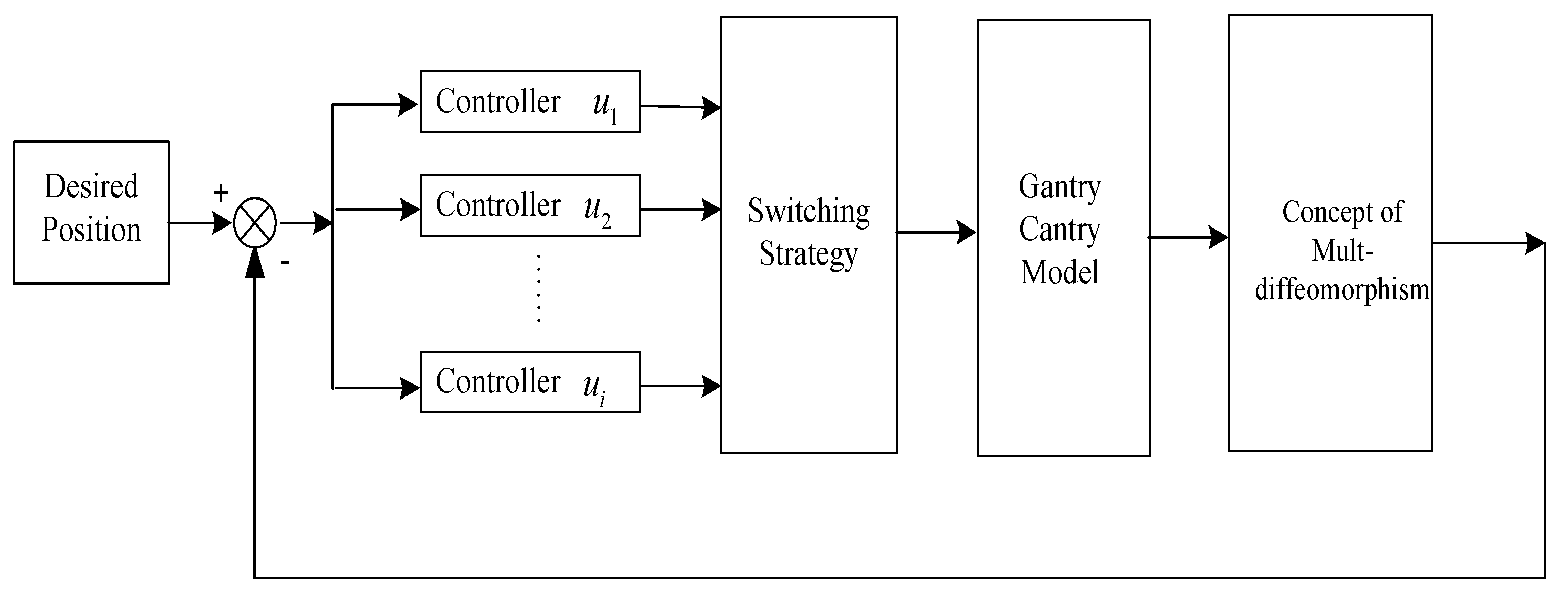
This work’s goal is to design a novel hybrid control strategy that uses friction to manage the location and nonlinearity of the sway angle gantry crane. Our work specifically attempts to provide a novel multi-diffeomorphism and feedback linearization of the switching systems strategy for switching control. This concept is based on the construction of a unique controller for each subsystem, which is intended to counteract the unstable zeros dynamics of each subsystem and make each mode stable on its own. Actually, by applying the stability principle, a switching strategy that produces the optimal transitional configuration for a nonlinear non-minimum phase switching system is proposed.
The structure of the hybrid control strategy with the gantry crane model is provided in the block diagram of Figure 3.
The main control objective is to regulate the swing angle ( θ 0 ) and drive it towards zero, corresponding to the vertical equilibrium position, while allowing the cart’s position to vary without restriction. In this configuration, the system defined in Equation (3) has a relative degree of r = 2, which is strictly less than the total number of states (n = 4). This implies the existence of internal dynamics that are not directly influenced by the input. While the system is not fully feedback linearizable, the presence of a well-defined relative degree permits its transformation into a normal form that separates the externally controlled dynamics from the internal behavior.
Although the classical notion of controllability is not directly applicable to nonlinear systems, the concept of relative degree plays a central role in characterizing the input–output relationship and designing appropriate controllers. In this work, the challenge of managing the internal dynamics, particularly in the non-minimum phase case, is addressed using a multi-diffeomorphism switching approach. By constructing a family of coordinate transformations and assigning a dedicated controller to each subsystem, the method ensures local stabilization of each mode and contributes to the global regulation of the overall system. This strategy ensures practical controllability by stabilizing both the external and the internal dynamics through hybrid coordination. Therefore, the system in Equation (3) satisfies the following lemmas:
Lemma 1.
There is a set of diffeomorphisms for every  i D = 1,2 ,
Φ i X = h X L F h X L F r h X φ 1 , i X φ n r , i X T
so that the following form is taken by the system of Equation (3):
Z ˙ 1 = Z 2 Z ˙ r = L F r h ( X ) + L G L F r 1 h ( X ) u i η ˙ 1 = Γ 1 , i Z , η η ˙ n r = Γ n r , i Z , η y = Z 1
and  δ 1 , i X , , δ n r , i X  ( j = 1 , , n r  and  i = 1 , , m ) are X-dependent nonlinear scalar functions that can be expressed explicitly using the following relation:
L G Z j , i X = 0
Accordingly, the gantry crane system is rewritten in its normal form by applying the coordinate transformation defined in Equation (4):
Φ i X = h X L F h X φ 1 , i X φ 2 , i X T
Equation (6), once resolved, leads to the determination of the dynamic compensator expressions for φ 1 , i X and φ 2 , i X . But, because there are many solutions, which result in an endless number of diffeomorphisms, the synthetic dynamic compensator is not unique. Three distinct diffeomorphisms are found by using the procedure outlined for determining the dynamic compensators’ expression, as follows:
Φ 1 X = X 3 X 4 X 1 X 4 + c o s X 3 L X 2
Φ 2 X = X 3 X 4 X 3 + X 1 X 3 X 4 + c o s X 3 L X 2
Φ 3 X = X 3 X 4 X 1 2 + s i n X 3 X 4 + c o s X 3 L X 2
As the balancing angle θ remains limited in this case, we may conceive of it as θ 0 , and the developed control strategy in this particular case should ensure the load is positioned perpendicular to the cart’s velocity. In light of the latter hypothesis, we may use the following approximations on the state as follows: c o s X 3 = 1 and s i n X 3 = X 3 .
We develop the nonlinear switching system for any subsystem i that is active. The following switching nonlinear system is created from the system described in Equation (3), and it satisfies Lemma 1:
X ˙ = f i X + g i X u i , i M
where the active subsystem is specified by a collection of indices denoted by i.
The mode i is either a minimum phase or a non-minimum phase depending on whether its zero dynamics η ˙ = Γ j , i 0 , η are unstable. The aim of this work is to stabilize non-minimum phase-switched nonlinear systems for each mode that have uncontrollable and unstable internal dynamics. We now want to develop a control law ui that stabilizes the dynamics of each subsystem i.
The following equation system is obtained by rewriting the normal form of Equation (5) into the system in Equation (11). Assuming that we can identify a partition X = Z η T for each mode i M :
Z ˙ = M r Z + β i Z , η + α i Z , η u i η ˙ = M Z i Z + M η i η + Ψ i Z , η
where
M r r × r = 0 1 0 0 0 0 1 0 0 0 0 1 0 0 0 , M Z i = Γ j , i Z , η Z / Z = 0 , η = 0 , M η i = Γ j , i Z , η η / Z = 0 , η = 0 δ i Z , η r × 1 = 0 0 δ ¯ i Z , η T
and β i Z , η r × 1 = 0 0 β ¯ i Z , η T .
After that, the system in Equation (12) may be expressed as follows:
Z ˙ η ˙ = M i Z η + H v i + 0 r Ψ i Z , η
with
M i = M r 0 r M Z i M η i and   H = 0 r 1 1 0 n r
For any subsystem i, we propose the following hybrid strategy for the auxiliary input v i = K i Z η T + u n l i , where K i = k 1 i k 2 i k n i is a row vector of constant gains and u N L i is a law of nonlinear control.
When we add Equations (11) and (12), we get:
Z ˙ η ˙ = M i H K i Z η + 0 r 1 u n l i Ψ i Z , η
Lemma 2.
Considering the system represented by Equation (14), in state space, if  K i  is selected in a way that makes  M i H K i  a Hurwitz polynomial, then  Q i > 0 , P i > 0 , such that:  M i H K i T P i + P i M i H K i = Q i .
Given each closed-loop mode i in a Lyapunov candidate function V i Z , η :
V i Z , η = Φ i T Z , η P i Φ i Z , η
The V i Z , η derivative can be obtained by:
V ˙ i Z , η = Z η T Q i Z η + 2 0 r 1 u n l i Ψ i Z , η T P i Z η
Our suggestion is to select u n l i , which satisfies:
0 r 1 u n l i Ψ i Z , η T P i Z η = 0
i.e.,
u n l i = k = r + 1 n Ψ k i Z , η P k l Z η P r l Z η
We can show that u N L i 0 when Z , η 0 .
Note that P 1 l , P 2 l , , P n l indicate the matrix’s column vectors P l , and
Ψ i Z , η = Ψ 1 i Z , η Ψ n r i Z , η T
Therefore, we have:
V ˙ i Z , η = Z η T Q i Z η < 0 , Z , η n
The dynamic feedback law introduced below is constructed to achieve precise input–output linearization of the system:
u i = β ¯ i Z , η δ ¯ i Z , η + v i δ ¯ i Z , η
The system in Equation (11), which expresses the system in Equation (13) in its normal form, becomes:
f i X = M i X + H β ¯ i X + Υ i X g i X = H δ ¯ i X
and Υ i X = 0 r Ψ i X T .
The system given by Equation (3) that fulfills Lemma 1 is converted by the three switched nonlinear subsystems as below:
-
Subsystem 1:
X ˙ = M 1 X + H β ¯ 1 X + Υ 1 X f 1 X + H δ ¯ 1 X g 1 X u 1
where
M 1 = 0 1 0 0 m g L 0 0 0 0 0 0 1 0 0 0 1 L Υ 1 X = 0 0 m g + m L X 3 X 4 2 M + m X 3 2 X 3 m L X 4 2 M L + m L X 3 2 T H = 0 1 0 0 ,   δ ¯ 1 X = 1 M L + m L X 3 2   and   β ¯ 1 X = M + m g X 3 m L X 4 2 M L + m L X 3
-
Subsystem 2:
X ˙ = M 2 X + H β ¯ 2 X + Υ 2 X f 2 X + H δ ¯ 2 X g 2 X u 2
where
M 2 = 0 1 0 0 M 0 1 L 0 0 0 0 1 0 0 0 m g L , Υ 2 X = 0 0 m g M + m X 3 2 X 3 m L X 4 2 M L + m L X 3 2 T ,   δ ¯ 2 X = m L M L + m L X 3 2   and   β ¯ 2 X = m L X 4 2 M L + m L X 3 2
-
Subsystems 3:
X ˙ = M 3 X + H β ¯ 3 X + Υ 3 X f 3 X + H δ ¯ 3 X g 3 X u 3
where
M 3 = 0 1 0 0 M L 0 1 L 0 0 0 0 1 m g 0 0 0 , Υ 3 X = 0 0 m g X 3 M + m X 3 2 m L X 4 2 M L + m L X 3 2 T , δ ¯ 3 X = L M L + m L X 3 2   and   β ¯ 3 X = m L X 4 2 + m L X 3 M L + m L X 3 2
For each subsystem i (i = 1, 2, 3), we design the controllers u 1 , u 2 , and u 3 using the same form as Equation (21). We select the quadratic Lyapunov functions as follows:
-
V 1 X for subsystem 1:
V 1 X = X 3 X 4 X 1 X 4 + X 2 L P 1 X 3 X 4 X 1 X 4 + X 2 L T
-
V 2 X for subsystem 2:
V 2 X = X 3 X 4 1 + X 1 X 3 X 4 + X 2 L P 2 X 3 X 4 1 + X 1 X 3 X 4 + X 2 L T
-
V 3 X for subsystem 3:
V 3 X = X 3 X 4 X 1 2 X 3 X 4 + X 2 L P 3 X 3 X 4 X 1 2 X 3 X 4 + X 2 L T
The stabilizing control laws u 1 , u 2 , and u 3 are derived based on a hybrid control framework that integrates the concept of multi-diffeomorphism with input–output feedback linearization. Each subsystem of the gantry crane model is transformed using a specific diffeomorphism, allowing the system to be expressed in a normal form that separates external dynamics (related to the output) and internal dynamics (related to zero dynamics). For every subsystem i, a feedback control input is defined per the structure presented in Equation (21).
By applying this control design to each mode (i = 1, 2, 3), we obtain the stabilizing laws u 1 , u 2 , and u 3 , as detailed in Equations (29), (30) and (31), respectively.
The stabilizing controller u 1 is:
u 1 = β ¯ 1 X δ ¯ 1 X + v 1 δ ¯ 1 X = m L X 3 v 1 X 4 2 + g m X 3 + M L v 1 + g X 3
with v 1 = k 1 1 X 3 k 2 1 X 4 k 3 1 X 1 X 2 k 4 1 L k 4 1 X 4 + u n l 1 and u n l 1 = j = 3 4 m L X 4 2 m g X 3 M g M + m X 3 2 P l j X 3 X 4 X 1 X 4 + X 2 L T .
The stabilizing controller u 2 is:
u 2 = β ¯ 2 X δ ¯ 2 X + v 2 δ ¯ 2 X = M + m g X 3 + m L X 3 v 2
with v 2 = k 1 2 X 3 k 2 2 X 4 k 3 2 X 1 + 1 X 3 k 4 2 X 4 k 4 2 X 2 L + u n l 2 and u n l 2 = j = 3 4 m L X 4 2 P l j X 3 X 4 1 + X 1 X 3 X 4 + X 2 L T .
The stabilizing controller u 3 is:
u 3 = β ¯ 3 X δ ¯ 3 X + v 3 δ ¯ 3 X = M g X 3 + m L X 3 v 3
with v 3 = k 1 2 X 3 k 2 2 X 4 k 3 2 X 1 2 X 3 k 4 2 X 4 + X 2 L + u n l 3 and u n l 3 = j = 3 4 M L + m L X 3 P l j X 3 X 4 X 1 2 X 3 X 4 + X 2 L T .
These laws guarantee both stability and swing angle suppression for each subsystem independently, and are then coordinated through a switching strategy to ensure global stability of the overall hybrid system.
To ensure the stability of each control mode, a Lyapunov function of the form V i X = X T P i X is constructed for every subsystem i = 1, 2, 3. The matrix Pi is symmetric, positive definite, and selected to satisfy the Lyapunov inequality for a chosen feedback gain Ki, such that the closed-loop matrix is Hurwitz. As a result, the time derivative of each Lyapunov function satisfies V ˙ i X = X T Q i X , with Qi also being positive definite. This ensures the asymptotic stability of each subsystem under the proposed feedback law. These results form the basis for the global switching stability analysis presented in the following section.

2.3. Switching Law Algorithm

In this section, we will provide the switching rules for the three stabilization control laws, using a potentially infinite set of diffeomorphisms. We aim to stabilize the crane model in Equation (3) with a switching strategy. The dynamic selection of the proper diffeomorphisms Φ 1 X , Φ 2 X , Φ 3 X is essential to this method to ensure the stability of the internal and external dynamics.
It should be recalled here that:
-
The local stability of a subsystem does not always guarantee the global stability of the entire system.
-
Global stability can result from a systematic strategy for alternating between unstable subsystems.
The proposed solution in this case is based on the application of the following lemma, theorem, and assumptions:
Assumption 1.
The system that was switched  X ˙ = f k j X + g k j X u k j ,   k j 1 ,   , d ,  and  j 0    is active for t j t < t j + 1 , where t is the amount of time that passes between two consecutive switches.
Assumption 2.
It is important that the formulation of the diffeomorphism in Equation (4), j 0   and for all X D X n , be:
ψ k j = Φ k j X X
It is verified whether a limit exists when X goes to zero ( X 0 ) .
In what follows, we will demonstrate the Lemma that applies a basic tool for characterizing the proposed approach.
Lemma 3.
The following inequality is confirmed by the exponential stability of Equation (3)’s solution when Lemma 2 is taken into consideration:
X t λ max λ min 1 2 ψ i X t 0 ψ i X X t 0 e ρ t t 0 2 λ max
where  ρ  represents Q’s minimal eigenvalue, and  λ max  and  λ min  stand for P’s maximum and minimum eigenvalues, respectively.
The switching law is therefore ensured according to the following four steps:
  • First Step: Initialization
    -
    Represent the first active subsystem 1 by initializing the index i = 1.
    -
    Establish the starting parameters X 1 0 , X 2 0 , X 3 0 , X 4 0 , and then calculate the transformed states Φ 1 X .
    -
    For each subsystem, define the matrices Pi, Qi.
  • Second Step: Confirming Conditions for Stability
    -
    Determine the active mode’s Lyapunov energy Vi(X).
    -
    Ensure that the following conditions are satisfied at every interval t i t < t i + 1 :
  • Case 1: Verified Switching Condition
In this case, a subsystem switch is triggered if the following inequality is fulfilled:
m i n ψ i + 1 X t i ψ i + 1 X t λ max P i λ min P i
This indicates that switching to the next subsystem (i + 1) will likely result in a reduced energy level (based on the Lyapunov criterion), thus contributing to system stability. The controller proceeds with the transition to mode i + 1.
  • Case 2: Unverified Switching Condition
If the inequality is not satisfied, it suggests that the current subsystem remains more favorable for stability. In this case, the system maintains the active control mode i without switching.
iii.
Third Step: Update Parameters
When the following mode has been chosen:
-
Increase the subsystem number: If i = 3, return to i = 1 to cycle through the subsystems.
-
Recalculate the states that have been changed: Implement the new diffeomorphism Φ k X .
iv.
Fourth Step: Stabilizing Control Law
Steps 1 through 3 should be repeated until convergence.
A stabilizing control law ui(X) should be applied to each active subsystem.
To provide a clearer understanding of the hybrid control strategy’s implementation, we have included a flowchart (as shown in Figure 4) that illustrates the main steps of the proposed switching algorithm. The procedure begins with the initialization of the subsystem index and the definition of the system’s initial state. For each active subsystem, the state transformation is computed using the corresponding diffeomorphism, followed by the definition of the Lyapunov-based matrices Pi and Qi. The algorithm then checks whether the convergence and switching conditions are satisfied. If so, the controller switches to the next subsystem, updates the transformed states, and applies the corresponding control law. If not, the current subsystem and control law remain active. This process is repeated iteratively until the system converges toward asymptotic stability. Figure 4 provides a structured visual representation of this logic, reinforcing both the practicality and the theoretical consistency of the proposed approach.

3. Simulation Results and Discussion

This section presents the results of testing the suggested control scheme in a simulated environment using the nonlinear gantry crane model in Equation (3) with the system characteristics listed in Table 1.
For u 1 , u 2 , and u 3 , we have chosen the values of gains k j i as follows:
k 1 1 = 10 , k 2 1 = 5 , k 3 1 = 15 , k 4 1 = 10 , k 1 2 = 12 , k 2 2 = 6 , k 3 2 = 18 , k 4 2 = 12 , k 1 3 = 15 , k 2 3 = 8 , k 3 3 = 20 , k 4 3 = 15
The gain values were determined through a heuristic tuning process involving iterative simulations. This approach aimed to satisfy the Hurwitz stability condition outlined in Lemma 2, while also enhancing the system’s dynamic performance by reducing overshoot and accelerating the convergence of the swing angle response.
The existence of the limit is confirmed by the components of l i m X 0 Φ 1 X / X , l i m X 0 Φ 2 X / X , and l i m X 0 Φ 3 X / X converging to finite (constant) values.
The Lyapunov functions Vi(X) for i = 1, 2, 3 are employed to determine the corresponding matrices Pi and Qi for each subsystem:
P 1 = 60.18 1.36 2.42 2.11 1.36 3.13 2.09 1.33 2.42 2.09 0.33 0.96 2.11 1.33 0.96 0.64 , P 2 = 49.08 1.12 1.70 1.53 1.12 2.57 1.73 1.11 2.42 2.09 0.33 0.96 2.11 1.33 0.96 0.64 , Q 1 = 1 0 0 0 0 1 0 0 0 0 1 0 0 0 0 1 P 3 = 39.30 0.93 0.89 1.11 0.93 2.11 1.29 0.93 0.89 1.29 0.25 0.59 1.11 0.93 0.59 0.44 , Q 2 = 10 0 0 0 0 1 0 0 0 0 5 0 0 0 0 1   and   Q 3 = 10 2 0 0 2 5 0 0 0 0 1 0 0 0 0 1
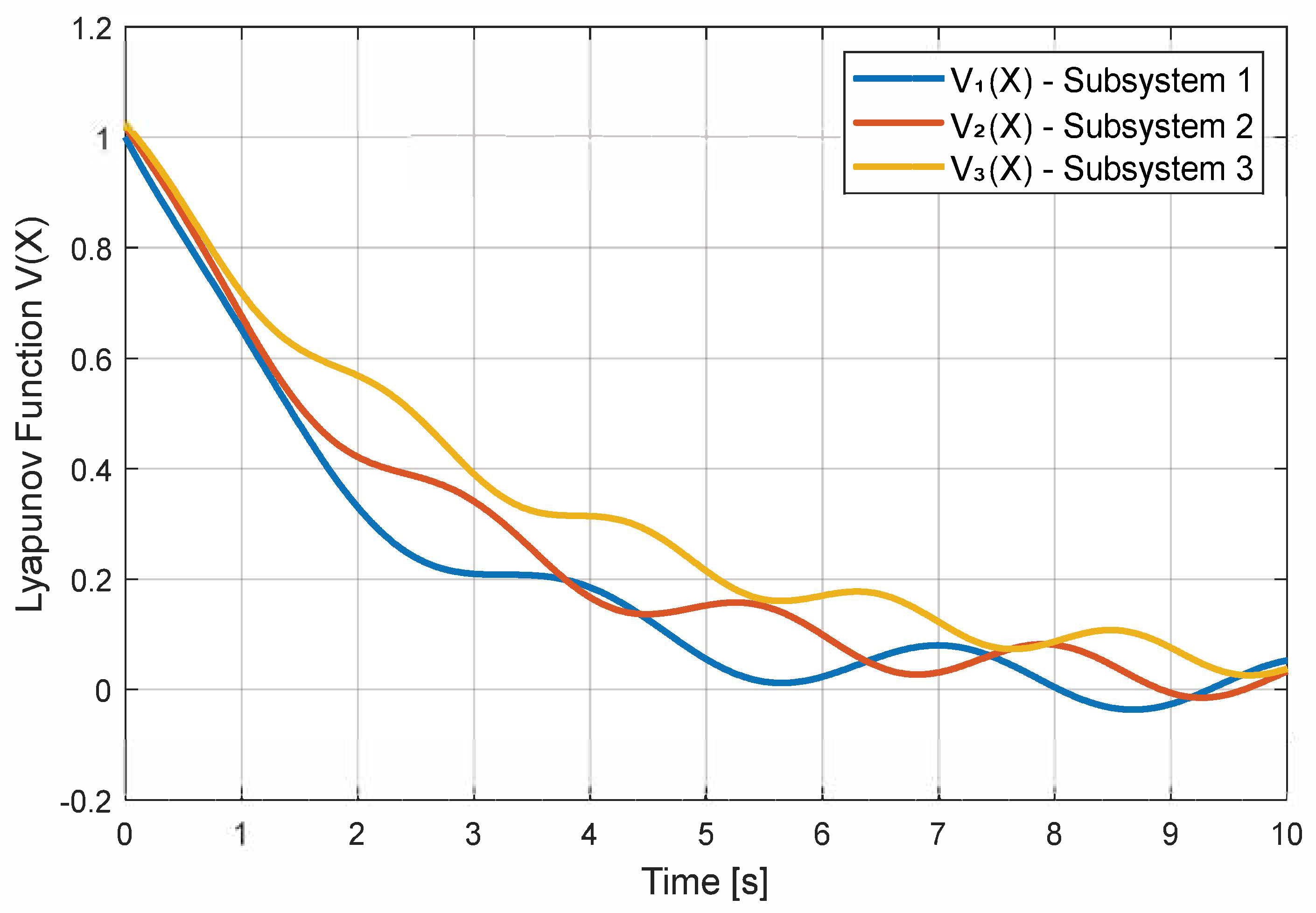
To further illustrate the theoretical stability guarantees, Figure 5 shows the temporal evolution of the Lyapunov functions V1(X), V2(X), and V3(X) for the three active subsystems. Each curve demonstrates a monotonic decrease toward zero, which confirms the asymptotic stability of the system under the proposed hybrid control strategy. The slight oscillations observed are due to the switching dynamics but remain bounded, thus supporting the effectiveness of the multi-diffeomorphism-based stabilization scheme.
Table 1 includes the parameters of the gantry crane used during the simulations.
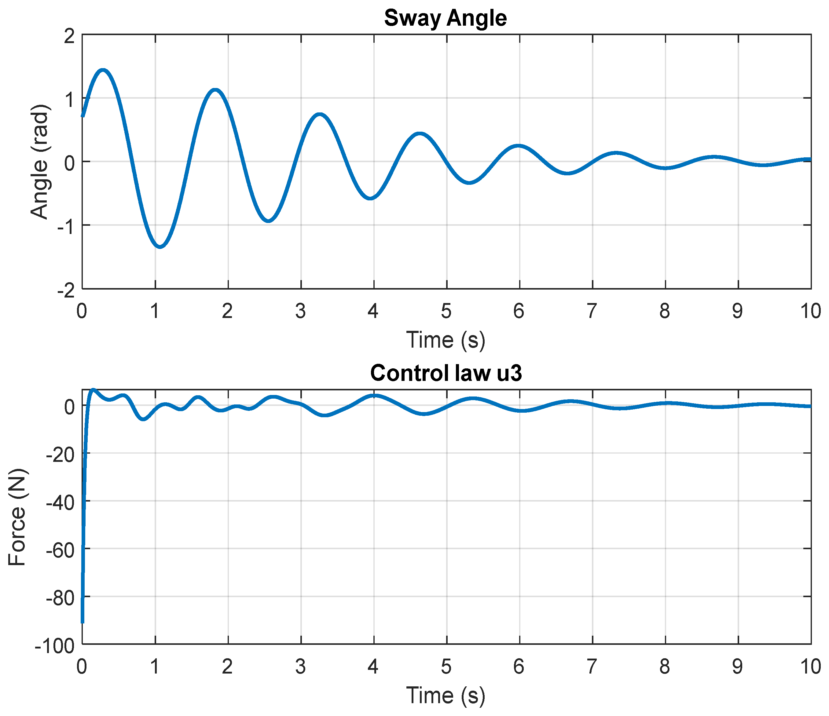
The simulation results are illustrated in Figure 6, Figure 7, Figure 8 and Figure 9, highlighting the behavior of the swing angle under different control transformations. Specifically, Figure 6, Figure 7 and Figure 8 correspond to the application of the first, second, and third diffeomorphisms (as defined in Equations (8), (9) and (10), respectively). In each of these cases, the swing angle exhibits noticeable oscillations and converges slowly toward the equilibrium point at zero, indicating limited stabilization performance.
The control inputs u 1 , u 2 , and u 3 , shown in Figure 6, Figure 7 and Figure 8, illustrate the dynamic behavior of the proposed control strategy across the three operating modes. Each signal evolves smoothly over time, with no abrupt discontinuities, which highlights the continuity and well-posedness of the control laws. The initial rise in amplitude corresponds to the controller’s response to the system’s starting deviation, aiming to quickly reduce the sway angle. As the system progresses toward equilibrium, the control signals gradually decrease in magnitude, indicating efficient stabilization. Overall, the signals remain within reasonable bounds throughout the operation, confirming that the hybrid approach avoids excessive control effort and ensures safe actuator behavior during transitions.
In contrast, Figure 9 illustrates the outcome when the control trajectory is generated using the multi-diffeomorphism approach. This configuration significantly improves the system’s stabilization: The swing angle converges rapidly to zero and remains tightly bounded around the equilibrium, with minimal residual oscillations. Compared to the single-diffeomorphism strategies shown in Figure 6, Figure 7 and Figure 8, the proposed method demonstrates enhanced damping and faster convergence.
To enhance the analysis of the proposed control strategies, we integrated quantitative performance indicators into the simulation study. Specifically, we evaluated the settling time, maximum overshoot, and root mean square error (RMSE) of the swing angle response under each control configuration: the three individual diffeomorphism-based controllers and the hybrid multi-diffeomorphism approach.
These metrics provide an objective basis for comparing the effectiveness of the control strategies in suppressing swing angle oscillations and accelerating convergence. The results are summarized in Table 2.
As shown, the multi-diffeomorphism strategy significantly outperforms the single diffeomorphism cases in all aspects: It achieves faster stabilization, lower overshoot, and more precise tracking, which demonstrates the benefit of switching between coordinated transformations.
To provide a more comprehensive assessment of the proposed control strategy, we included a comparison with a conventional approach widely used for underactuated systems: input–output feedback linearization based on a single diffeomorphism. Both methods were tested under identical conditions, using the same system parameters and performance metrics.
The evaluation focused on three key indicators of control performance: settling time, maximum overshoot, and root mean square error (RMSE) of the swing angle. These metrics offer a precise and objective way to quantify system behavior.
As summarized in Table 3, the hybrid multi-diffeomorphism strategy achieves significantly better results across all indicators. It reduces oscillations more effectively, speeds up system stabilization, and yields more accurate tracking. These improvements demonstrate the added value of using multiple coordinated diffeomorphisms and a switching mechanism, particularly in systems exhibiting non-minimum phase dynamics.
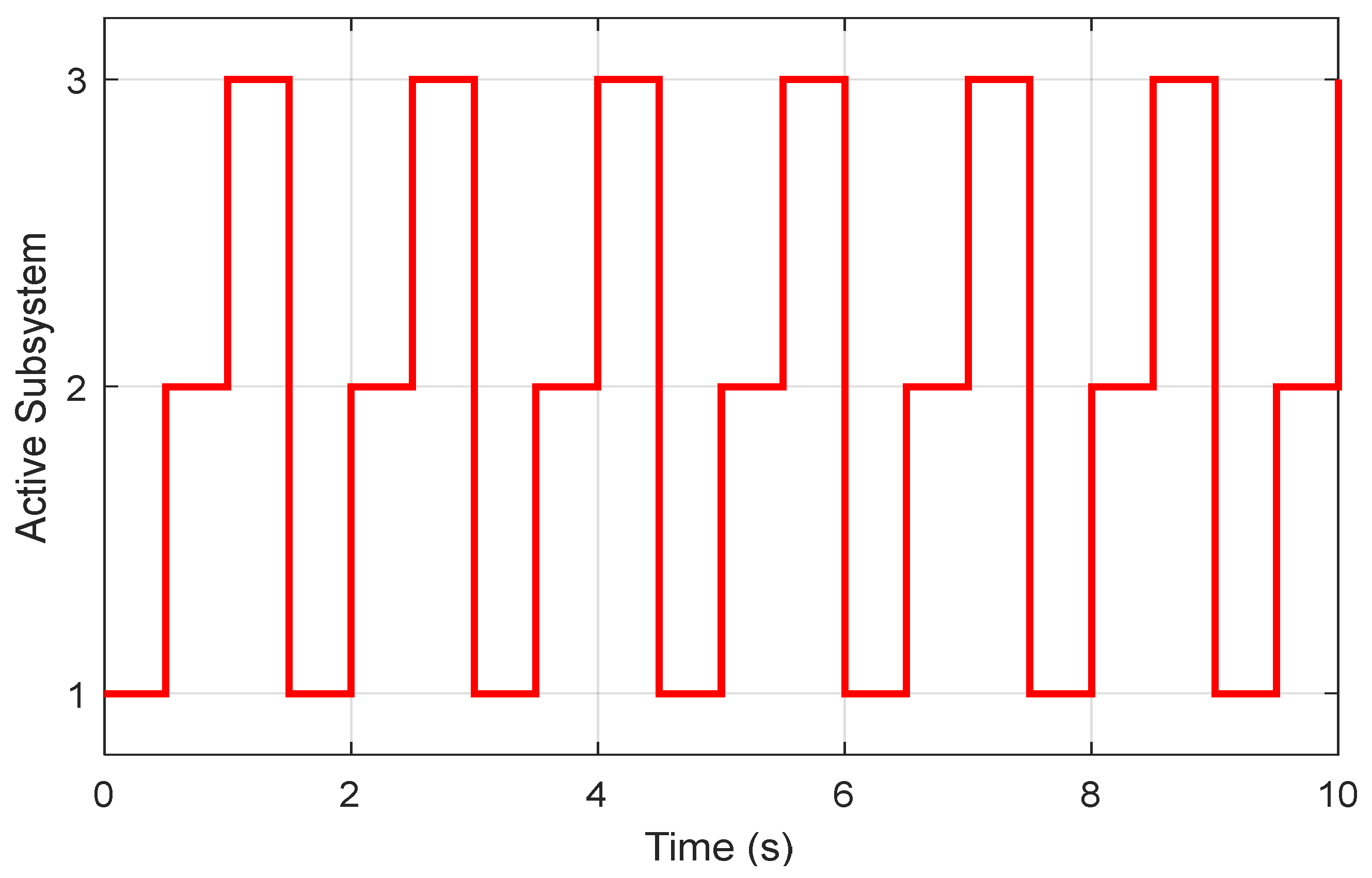
To further illustrate the behavior of the proposed switching strategy, a dedicated simulation was conducted, during which the active control mode alternated rapidly among the three designed subsystems. The switching occurred every 0.5 s, mimicking a high-frequency transition scenario. Figure 10 presents the evolution of the active subsystem index over time. As shown, the controller transitions cyclically through the modes {1, 2, 3}, demonstrating the system’s ability to accommodate frequent changes in control laws without destabilizing the switching mechanism. This scenario is particularly useful for evaluating the robustness and responsiveness of the proposed hybrid approach under dynamic operating conditions.

4. Conclusions

In this study, a hybrid control strategy was developed for nonlinear switched systems with potential non-minimum phase subsystems, taking a gantry crane as an illustrative example. The approach is based on a novel use of multi-diffeomorphism transformations, allowing each subsystem to be feedback-linearized locally, even when global linearization is infeasible. Unlike traditional methods that rely on a single transformation, this framework enhances both stability and transient performance by distributing the control effort across multiple coordinated subsystems. Lyapunov-based control laws were designed for each mode to ensure local stabilization, and a switching rule based on an average dwell time was introduced to guarantee global asymptotic stability. Numerical simulations demonstrated that the proposed method effectively suppresses swing oscillations and provides fast convergence, even in the presence of disturbances or frequent switching. This makes it a promising solution for underactuated systems with complex internal dynamics. Future work will address the implementation aspects and extensions to more general classes of nonlinear hybrid systems.

Author Contributions

Conceptualization, S.S., S.B. and K.J.; funding acquisition, S.S.; methodology, K.J. and S.B.; project administration, S.S.; validation, S.B.; visualization, K.J.; writing—original draft, K.J. and S.B.; writing—review and editing, S.S. All authors have read and agreed to the published version of the manuscript.

Funding

University of Jeddah, Jeddah, Saudi Arabia, grant No. (UJ-24-DR-20377-1).

Data Availability Statement

The original contributions presented in this study are included in the article. Further inquiries can be directed to the corresponding author.

Acknowledgments

This work was funded by the University of Jeddah, Jeddah, Saudi Arabia, under grant No. (UJ-24-DR-20377-1). Therefore, the authors thank the University of Jeddah for its technical and financial support.

Conflicts of Interest

The authors declare no conflicts of interest.

References

  1. Le, A.; Lee, S.-G. 3D Cooperative Control of Tower Cranes Using Robust Adaptive Techniques. J. Frankl. Inst. 2017, 354, 8333–8357. [Google Scholar] [CrossRef]
  2. Tuan, L.; Lee, S.-G.; Dang, V.H.; Moon, S.C.; Kim, B. Partial Feedback Linearization Control of a Three-Dimensional Overhead Crane. Int. J. Control Autom. Syst. 2013, 11, 718–727. [Google Scholar] [CrossRef]
  3. Matsuo, T.; Yoshino, R.; Suemitsu, H.; Nakano, K. Nominal Performance Recovery by PID+Q Controller and Its Application to Anti-Swing Control of Crane Lifter with Visual Feedback. IEEE Trans. Control Syst. Technol. 2004, 12, 156–166. [Google Scholar] [CrossRef]
  4. Solihin, M.; Wahyudi; Legowo, A. A Fuzzy-Tuned PID Anti-Swing Control of Automatic Gantry Crane. J. Vib. Control 2010, 16, 127–145. [Google Scholar] [CrossRef]
  5. Ngo, Q.; Hong, K.S. Sliding-Mode Antisway Control of an Offshore Container Crane. IEEE/ASME Trans. Mechatron. 2012, 17, 201–209. [Google Scholar] [CrossRef]
  6. Ngo, Q.; Hong, K.S. An Adaptive Sliding Mode Control of Container Cranes. IET Control Theory Appl. 2012, 6, 662–668. [Google Scholar] [CrossRef]
  7. Vázquez, C.; Collado, J.; Fridman, L. Super Twisting Control of a Parametrically Excited Overhead Crane. J. Frankl. Inst. 2014, 351, 2283–2298. [Google Scholar] [CrossRef]
  8. Tuan, L.; Lee, S.-G.; Moon, S.C. Partial Feedback Linearization and Sliding Mode Techniques for 2D Crane Control. Trans. Inst. Meas. Control 2014, 36, 78–87. [Google Scholar]
  9. Maghsoudi, M.; Mohamed, Z. Active Sway Control of a Gantry Crane by an Electrical Ducted Fan. Int. J. Acoust. Vib. 2015, 20, 171–176. [Google Scholar] [CrossRef]
  10. Maghsoudi, M.; Mohamed, Z. Control of a Gantry Crane Using Input-Shaping Schemes with Distributed Delay. Trans. Inst. Meas. Control 2017, 39, 361–370. [Google Scholar] [CrossRef]
  11. Abdullahi, A.; Mohamed, Z.; Abidin, M.S.; Buyamin, S.; Bature, A. Output-Based Command Shaping Technique for an Effective Payload Sway Control of a 3D Crane with Hoisting. Trans. Inst. Meas. Control 2016, 39, 1443–1453. [Google Scholar] [CrossRef]
  12. Sirisena, H. Ripple-Free Deadbeat Control of SISO Discrete Systems. IEEE Trans. Autom. Control 1985, 30, 168–170. [Google Scholar] [CrossRef]
  13. Paz, R. Ripple-Free Tracking with Robustness. Int. J. Control 2006, 79, 543–568. [Google Scholar] [CrossRef]
  14. Isidori, A. Nonlinear Control Systems: An Introduction; Springer: New York, NY, USA, 1995. [Google Scholar]
  15. Zhao, X.; Wang, X.; Zong, G.; Zhou, J. Fuzzy-Approximation-Based Adaptive Output-Feedback Control for Uncertain Non-Smooth Nonlinear Systems. IEEE Trans. Fuzzy Syst. 2018, 26, 3847–3859. [Google Scholar] [CrossRef]
  16. Chang, X.H.; Wang, Y.M. Peak-to-Peak Filtering for Networked Nonlinear DC Motor Systems with Quantization. IEEE Trans. Ind. Inform. 2018, 14, 5378–5388. [Google Scholar] [CrossRef]
  17. Wang, M.; Dimirovski, G.M.; Zhao, J. H∞ Control for a Class of Non-Minimum Phase Cascade Switched Nonlinear Systems. In Proceedings of the American Control Conference, Seattle, WA, USA, 11–13 June 2008. [Google Scholar]
  18. Jouili, K.; Benhadj, B.N. Stabilization of Non-Minimum Phase Switched Nonlinear Systems with the Concept of Multi-Diffeomorphism. Commun. Nonlinear Sci. Numer. Simul. 2015, 23, 282–293. [Google Scholar] [CrossRef]
  19. Yang, H.; Jiang, B.; Zhang, H. Stabilization of Non-Minimum Phase Switched Nonlinear Systems with Application to Multi-Agent Systems. Syst. Control Lett. 2012, 61, 1023–1031. [Google Scholar] [CrossRef]
  20. Zhao, X.D.; Zheng, X.L.; Liu, B.; Wu, Y. Adaptive Tracking Control for a Class of Uncertain Switched Nonlinear Systems. Automatica 2015, 52, 185–191. [Google Scholar] [CrossRef]
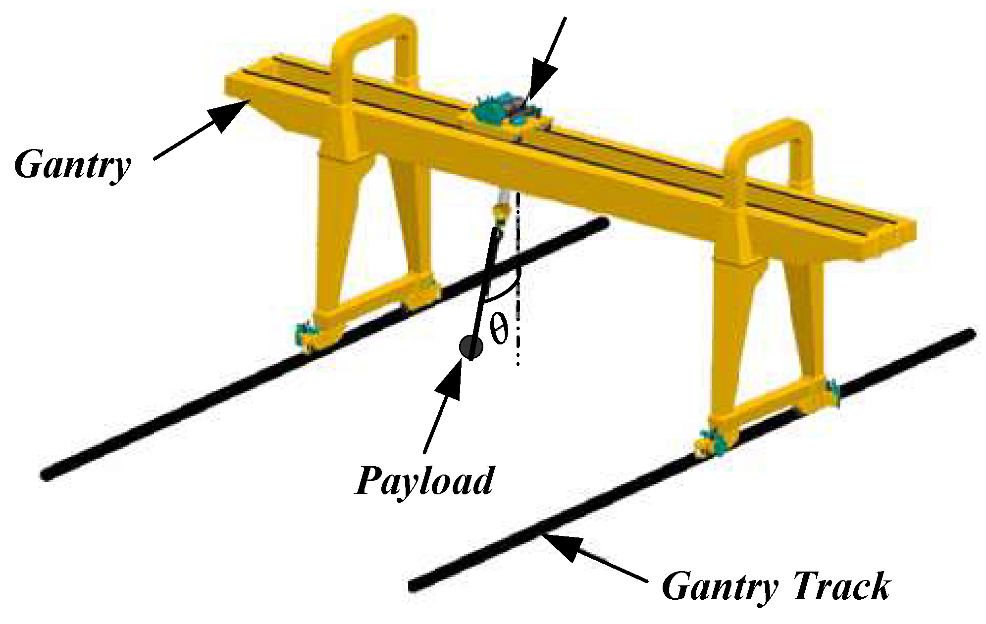
Figure 1. Typical gantry crane structure.
Symmetry 17 01302 g001
Figure 2. Schematic diagram of the crane system.
Symmetry 17 01302 g002
Figure 3. Block diagram of the hybrid control strategy.
Symmetry 17 01302 g003
Figure 4. Flowchart of the switching law algorithm for the hybrid gantry crane control strategy.
Symmetry 17 01302 g004
Figure 5. Time evolution of Lyapunov functions V1(X), V2(X), and V3(X) for each subsystem, showing consistent decay and confirming system stability under the hybrid control law.
Symmetry 17 01302 g005
Figure 6. Stabilizing controller u 1 X and the sway angle that is related to the first diffeomorphism Φ 1 X .
Symmetry 17 01302 g006
Figure 7. Stabilizing controller u 2 X and the sway angle that is related to the second diffeomorphism Φ 2 X .
Symmetry 17 01302 g007
Figure 8. Stabilizing controller u 3 X and the sway angle that is related to the third diffeomorphism Φ 3 X .
Symmetry 17 01302 g008
Figure 9. The switching stabilizing controller and the multi-diffeomorphism notion ( Φ 1 X , Φ 2 X and Φ 3 X ) are used to evolve the sway angle.
Symmetry 17 01302 g009
Figure 10. Frequent mode switching among subsystems. The red line indicates the sequence of active subsystems (1, 2, and 3).
Symmetry 17 01302 g010
Table 1. Parameters of the gantry crane system.
ParametersValue
Mass of the cart M = 1   kg
Mass of the rod m = 1.1   kg
Length of the rod L = 0.45   m
Gravitational acceleration g = 9.81   m / s 2
Constant friction car d = 20   Ns / m
Constant friction payload b = 0.001   Ns / m
Table 2. Performance indicators for each control strategy.
Control StrategySettling Time (s)Maximum Overshoot (°)RMSE (°)
Diffeomorphism 1 (Φ1)6.211.53.42
Diffeomorphism 2 (Φ2)5.79.82.87
Diffeomorphism 3 (Φ3)5.48.12.41
Hybrid multi-diffeomorphism3.12.60.94
Table 3. Quantitative comparison with a classical control method.
Control MethodSettling Time (s)Max Overshoot (°)RMSE (°)
Classical I/O feedback linearization6.812.34.05
Hybrid multi-diffeomorphism (proposed)3.12.60.94
Disclaimer/Publisher’s Note: The statements, opinions and data contained in all publications are solely those of the individual author(s) and contributor(s) and not of MDPI and/or the editor(s). MDPI and/or the editor(s) disclaim responsibility for any injury to people or property resulting from any ideas, methods, instructions or products referred to in the content.