Abstract
The dynamic behavior of pipelines subjected to additional masses is crucial for optimizing the design and reliability of engineering systems, particularly in offshore and industrial applications. This study investigates the effect of slenderness on the dynamic response of a pipe with one or more additional masses placed at different positions along its length, considering the symmetry of the system in mass distribution. The aim is to analyze how mass placement influences vibration characteristics under fluid–structure interaction (FSI) conditions. The pipe is modeled as a Rayleigh beam, and the governing equations of motion are derived using Hamilton’s principle while preserving the inherent symmetry of the system. A non-dimensionalized approach is employed to ensure broad applicability across different geometric and material configurations. The vibration frequencies are obtained using the Galerkin method (GM) and validated via a two-way FSI technique, integrating computational fluid dynamics (CFDs) and structural mechanics using ANSYS 2022 software. The results demonstrate the relationship between the concentrated mass ratio and vibration frequency for the first three modes, highlighting the influence of slenderness ratio on system stability. These findings provide valuable insights for the engineering design of pipeline systems subjected to dynamic loading.
1. Introduction
With the advancement of technology, the stability and dynamic behavior of symmetric fluid-conveying pipes have become critical concerns. Dynamical models, which are widely used in various industrial sectors, are often represented by fluid-conveying pipe systems [1]. This subject has been thoroughly investigated by numerous researchers under various boundary conditions. Early research focused on the vibration analysis of beam–mass systems [2,3,4,5,6]. However, the dynamic analysis of fluid-carrying pipes was not conducted until 1970. Measurement devices such as flowmeters, heavy valves, and connectors are widely used in industrial applications and are studied as symmetric pipe–mass systems [7,8]. Kang concluded that the higher natural frequencies and mode shapes of fluid–pipe–mass systems can be influenced by the incorporation of rotational inertia [9]. Ghayesh et al. developed an approximate analytical solution for predicting the phase shift along the length of a Coriolis mass flowmeter [10], where the equation of motion was numerically solved using the Galerkin method. Their study demonstrated that the analytical predictions were in agreement with the numerical results.
The dynamic analysis of pipes modeled using Euler–Bernoulli beam theory was investigated by Varol and Sınır. The variations in the natural vibration frequency were evaluated by considering the position and magnitude of concentrated masses as well as the velocity of the fluid inside the pipe [11]. In an experimental study conducted by Goyder on an L-shaped pipe, damping ratios were presented using vanes considered as additional mass. A comparison with a system without vanes showed that the presence of vanes significantly increased the damping [12]. Zhang et al. analyzed the system using lumped masses and linear springs, modeling the pipe based on the Euler–Bernoulli beam theory. The reliability of the proposed set of equations was evaluated by comparing the results of linear stability analysis among various models, highlighting the role of symmetric mass distribution in dynamic stability [13]. Rayleigh beam theory, which incorporates rotational inertia effects, has been widely applied in various engineering fields due to its ability to provide a more accurate representation of the dynamic behavior of slender structures. Recent studies, such as [14,15], have demonstrated its effectiveness in specific projects, including aeronautics, astronautics, and marine, deep-sea mining.
In the present paper, a more refined model for the vibration of a slender symmetric pipe–mass system is established to investigate the sensitivity of the pipe buckling effect. Unlike previous works, this research employs a Rayleigh beam model combined with a non-dimensionalized approach. The effects of flowmeters on dynamic behavior are investigated by defining concentrated masses at different locations on the pipe. These masses, representing devices used for volumetric flow measurement of fluids, are incorporated into the mathematical model using the Dirac delta function. The energy exchange between the fluid and pipe is considered. The beam motion equation is derived using the variational iteration method [16]. To ensure the broad applicability of the results to different materials and geometric configurations, the governing equations are non-dimensionalized. Non-dimensional velocity, mass ratio, slenderness ratio, and concentrated mass ratio are obtained for the symmetric Rayleigh pipe model, allowing for a more generalizable and adaptable framework. The magnitude and location of the concentrated mass are used as control parameters. To solve the equations of motion, the Galerkin method (GM) and a computational two-way FSI technique are employed. Realistic conditions are achieved using ANSYS software, which simulates the interaction between solid and fluid surfaces considering the symmetry of the problem [17]. Additionally, numerical methods are utilized for comparison and validation, ensuring the reliability of the obtained results. By establishing a direct relationship between the concentrated mass ratio, slenderness ratio, and vibration frequency, this study provides new insights into pipeline stability and resonance behavior, which are crucial for offshore and industrial applications. These contributions make this study distinct from the existing literature and enhance its applicability in engineering design.
2. Mathematical Model of Motion
The motion of the system occurs in a plane. The spatial coordinate is represented by , while the transverse displacement is denoted by . The axial flow velocity is defined as . The pipe is modeled as a straight and homogeneous structure with a length of L. The densities of the pipe (ρp) and the fluid (ρf), along with their cross-sectional areas (Ap, Af), are assumed to be constant. The subscripts p and f correspond to the pipe and the fluid, respectively. The physical properties of the pipe are characterized by the elasticity modulus (E) and the moment of inertia (Jp). The fluid is considered incompressible, and the effects of viscosity are neglected. Point (concentrated) masses in the system are represented by ms, and their positions on the pipe are denoted by . Furthermore, the rotational inertia effect arising from the angular acceleration of the point masses is disregarded.
Through certain mathematical manipulations [18,19,20,21], the dynamic equation of the transverse vibration of a Rayleigh pipe conveying incompressible fluid and containing concentrated masses in the Laplace domain has been derived.
Here, time is denoted by , while physical quantities are represented using superscripts (^) to emphasize the dimensional properties of the parameters. In cases where the flow is considered steady and inviscid, time-dependent partial derivatives and viscosity-related terms are neglected. This assumption significantly simplifies the analysis, allowing a focus solely on the fundamental dynamic properties of the fluid and the motion of the pipe. As a result, the study primarily examines how the system behaves under inertial forces and pressure effects. To model the effects of concentrated (point) masses within the system, the Dirac delta function, δ(x), is utilized. This function mathematically represents that the influence of point masses is localized at specific positions, with no effect on the rest of the system. In engineering analyses, the Dirac delta function is particularly useful for representing the effects of concentrated masses and external forces acting on the system.
To analyze the dynamic behavior of the system in a more comprehensive and generalized manner, the parameters in Equation (1) are non-dimensionalized. The non-dimensionalization process is a crucial step in examining the fundamental physical processes of the system independently of specific scales. By doing so, the general characteristics of pipeline dynamics under varying diameters, thicknesses, and hydrodynamic forces can be identified, enhancing the applicability of the results to different engineering scenarios. This non-dimensionalization process is carried out using the mathematical definitions and variable transformations provided below:
Here, represents the radius of gyration used to non-dimensionalize the displacement. The radius of gyration is a fundamental physical quantity that describes the distribution of a body’s mass relative to its axis of rotation, and it plays an important role in dynamic analysis of the system. The non-dimensional fluid velocity indicates the relative speed of the fluid flowing inside the pipe compared to the structural properties of the system, affecting the stability and vibration characteristics. Non-dimensionalizing the displacement parameter allows for the analysis of systems with different physical dimensions and scales under a unified framework. This method makes it possible to compare the general dynamic behavior of systems under various combinations of factors such as diameter, thickness, and mass distribution. It facilitates modeling and comparison of systems independently of scale in various engineering applications.
As a result, the motion equation in its dimensionless form can be derived as follows [8,11]:
The mass ratio, defined as , varies between 0 and 1. The mass ratio defines the proportion of the fluid mass relative to the total system mass, determining whether the dynamic response is dominated by the fluid inertia or the structural properties of the pipe. When the mass ratio approaches 1, the dynamics of the system become dominated by the fluid, while for values closer to 0, the pipe’s inertia plays a more significant role. In the special case where β = 1, the governing equation reduces to the behavior of an axially moving beam, eliminating the influence of internal fluid mass on the structural response. The concentrated mass is expressed as follows:
where mp is the mass of the pipe, and mf is the mass of the fluid per unit length. In Equation (4), the rotary inertia factor accounts for the rotational effects of mass elements about the pipe’s neutral axis. It influences the dynamic behavior of the pipe by considering mass distribution and angular acceleration. This factor becomes particularly important in high-frequency vibrations or short-wavelength disturbances, where rotational inertia cannot be neglected.
The parameter λ, known as the slenderness ratio, is a dimensionless coefficient that characterizes the pipe’s susceptibility to buckling. It provides insight into the relative importance of bending stiffness versus axial forces in determining the stability of the structure. A higher slenderness ratio typically indicates increased sensitivity to buckling under compressive loads, making it a crucial factor in pipeline design, especially for offshore and deep-sea applications. The slenderness ratio can be mathematically expressed as follows:
The slenderness ratio is one of the key parameters influencing the dynamic behavior of pipe–mass–fluid systems. A comprehensive analysis of system instability is achieved when the buckling condition is taken into account [22,23]. The slenderness ratio of a pipe can be adjusted by modifying either its diameter or length, making it a crucial design parameter in structural applications. For steel structural members, the slenderness ratio typically ranges between 10 and 250, depending on the geometric and material properties of the system. To evaluate the influence of the slenderness ratio on natural frequencies, three representative values, λ = 10, 20, 30, are considered in this study. These values allow for a systematic examination of how slenderness affects the vibrational characteristics of the pipe. Additionally, the effect of creep deformation, which could influence long-term stability, is neglected by selecting low slenderness ratio values [24,25]. Since the pipe undergoes displacement , the boundary conditions for a pinned–pinned pipe with multiple concentrated masses are illustrated in Figure 1. These conditions define the constraints on pipe motion and play a crucial role in determining the overall dynamic response of the system.
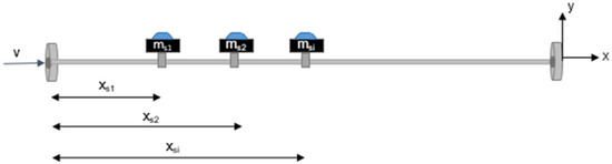
Figure 1.
Schematic diagram of the simply supported pipe.
In this case, the equation of motion is rewritten as follows:
In order to solve Equation (7), the dimensionless lateral displacement can be given as
where represents a temporal function and is the nth mode of the system. By inserting Equation (8) into Equations (4) and (7), the dimensionless governing equations of single and multiple pipe–mass systems become
3. Numerical Analysis Procedure
3.1. Galerkin Method
The Galerkin method is used to approximate the partial differential equations by piecewise trial functions [26,27]. The dimensionless nth mode of the pipe, , can be given by the superposition of , which is the dimensionless shape function.
The following expansion is obtained by applying the Galerkin method:
The mode shapes can be written by Equation (12) according to a simply supported pipe system [28]:
The orthogonality of functions is obtained by multiplying the resulting equation without the terms of concentrated mass by and then integrating about x over the domain [0, 1], as given by the following equation [26]:
Here, is Kronecker’s delta, is dimensionless eigenvalue of the pipe, and the relation is defined as follows:
In addition, Bmn, Cmn. can be written as
The governing equation of Rayleigh pipe can be given in the matrix form as follows:
Here, is the overall vector of generalized coordinates, is a diagonal matrix, and its main diagonal is occurred by . B, C represent the matrices with elements Bmn, Cmn.
The terms of concentrated mass multiply by and integrate from 0 to 1 to obtain the final from of the equation of motion. This additional term is represented by
By adding Equation (17) into Equation (16), the governing equation is achieved. This method was utilized by Hill and Swanson [29]. The following simple standard expression for the equations of motion can be given as
Here, , , and represent the mass, damping, and stiffness matrices of the pipe system. Equation (18) needs to convert to a first-order form to calculate the eigenvalue problem. Assuming the state vector , Equation (18) is transferred into the first-order form as follows:
where
Substituting the into Equation (19), the following eigenvalue problem is obtained:
Here, is the unitary matrix, and . The solution code that uses iteration techniques has been created for solving eigenvalue problem [8]. Maple computer algebra system has been utilized for tailoring the transactions to the computer code. The flow chart of the developed code is given in simplified form in Figure 2.
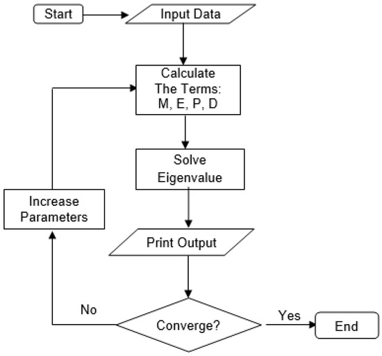
Figure 2.
The flow chart for software program.
This code is used to determine the eigenvalues and eigenvectors, which are essential for calculating the natural frequencies and mode shapes of the system. The accuracy and convergence of the obtained results are evaluated by progressively increasing the value of n, ensuring that the computed natural frequencies and mode shapes remain consistent and reliable. This iterative approach helps verify the stability and correctness of the numerical solution.
3.2. Computer-Aided FSI Analysis Procedure
Two key disciplines involved in pipe analysis are fluid dynamics and structural dynamics. This fluid–structure interaction problem spans multiple domains, requiring coupled system formulations. In this study, two-way coupled simulations were conducted using ANSYS software. ANSYS Fluent was employed for the fluid domain, while ANSYS Mechanical was used for the structural domain. ANSYS System Coupling facilitated the interaction between these domains by defining contact surfaces.
In the simulation process, the results from ANSYS Fluent at the fluid–structure interface were transferred to ANSYS Mechanical and applied as loads. Each model was developed independently, utilizing separate mesh structures, boundary conditions, analysis configurations, and output parameters to ensure accuracy and flexibility in the simulation. The workflow for multi-field simulations using ANSYS is illustrated in Figure 3 [30].
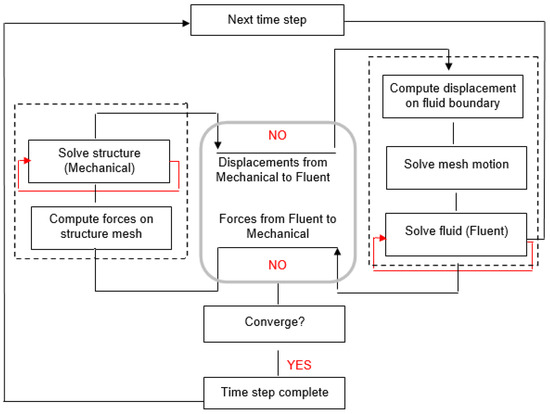
Figure 3.
Flow chart for multi-field simulations with ANSYS.
In the mechanical application, the structural model of the pipe is meshed and the fluid part is suppressed. The physical properties of the material are represented in Table 1.

Table 1.
Specifications of the pipe.
It is assumed that the material will comply with the associated Prandtl–Reuss flow rule and von Mises yield criterion [31]. Dynamic behavior of the system is determined considering three different cases. These three cases, according to D/L and λ, are given in Table 2, and the pipe consists of total length L = 10 m for all models.
Table 2.
Case explanations.
To verify the effect of concentrated masses on the natural frequencies, five values of xs = 1.00 m, 2.00 m, 3.00 m, 4.00 m, 5.00 m and two values of = 0.10, 0.20 are assumed. The following parameter β is considered as 0.50 for both cases to ensure symmetry. ANSYS Multiphysics is employed to develop the structural model of the pipe. This model experiences transient deformation in response to pressure fluctuations computed by the fluid model using the displacement diffusion algorithm. For transient structural analysis, the geometry of the structural component is accurately defined, and a computational structural mechanic (CSM) finite element mesh is generated for the pipe. The detailed geometry and mesh structure of the structural model are illustrated in Figure 4.
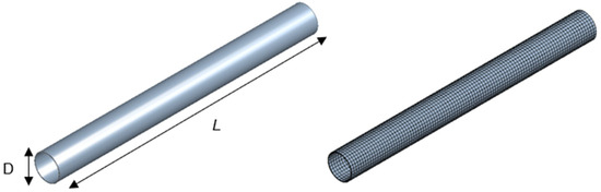
Figure 4.
Structural member and mesh.
The finite element mesh used here is SHELL181. The CFD (computational fluid dynamic) mesh of this study is a hybrid mesh combination of tetrahedral and prism layers. Mesh displacements are satisfied on contact surfaces by modeling FSI coupling. A grid refinement study has been performed to ensure the simulation results are independent of the mesh. The mesh sizes are selected based on a trade-off between computational efficiency and accuracy. Convergence is assessed by monitoring the force and displacement residuals at the interface. A maximum difference of 7% is observed between peak values, indicating that the solution is sufficiently mesh-independent. The mesh numbers of the fluid and solid domains are provided in Table 3 due to the cases.
Table 3.
Case explanations.
The ANSYS Mechanical set up work consists of defining the boundary conditions, loads, and analysis settings. The simulation set up members of the pipe can be seen in Figure 5.
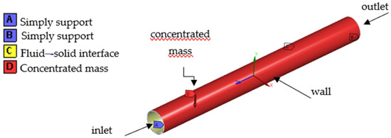
Figure 5.
The simulation set up members.
The fluid is realized as ideal and incompressible. The effects of turbulence are neglected. Concentrated masses are identified as forces that are effective on assigned nodes. The ends of the pipe are symmetrically fixed by simply supports, and the calculated fluid forces are applied on the model. Appropriate names are assigned to all inlets, outlets, and walls in Fluent, which uses finite volume method [32]. In two-way FSI analyses, resulted fluid flow calculation is interpolated to the structural model at the interface. The two-way coupling approach involves an iterative process where both the fluid and structural solvers interact continuously. Here, the fluid forces are applied to the structure, and the resulting structural deformations modify the fluid flow. This feedback loop continues until convergence is reached, resulting in a more accurate representation of the coupled system. Although two-way coupling is computationally more demanding, it is essential for capturing the true dynamics in systems where the interaction between fluid and structure is strong [33].
The equation given below is utilized to determine the values of displacements by explicit analysis:
Here, is acceleration, is the mass matrix, represents load vector transferred from CFD, and is internal force vector due to stresses. The equations of motion can be integrated according to following equations:
In Equations (23a) and (23b), and symbolize displacement and velocity components, respectively. The nodal accelerations are given by the following definition:
The values of displacements are calculated after obtaining accelerations. In this study, the analyses are observed during 10 s, and the time step size is assumed as 0.01 s. The shapes of natural frequencies for the initial three modes are given by Figure 6.
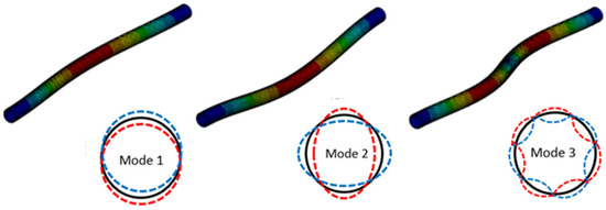
Figure 6.
The initial three mode shapes.
4. Results and Discussion
First, the natural frequency values have been computed for various ζ values for the initial three modes assuming one concentrated mass. In order to validate the Galerkin method (GM) and two-way FSI technique, three cases are taken into account in Table 4. Introduction of the rotary inertia factor () gives much change for the second and third modes while it gives relatively small influence on the first mode. The difference between the dimensionless natural frequencies in Case I and Case II is within 0.001–0.011% error bounds and in Case II and Case III is within 0.001–0.002% error bounds. These results confirm that the natural frequencies have similar values regardless of the increase in slenderness ratio for greater values of λ. Due to the different location of the concentrated mass, much variation in the natural frequencies is given compared to slenderness ratio [34,35].
Table 4.
Comparison of natural frequency values for one concentrated mass (β = 0.5, , v = 0.5).
As shown in Table 4, the natural frequency decreases as the concentrated mass is shifted toward the symmetry axis at the middle of the pipe for the first mode. When ms is located at ζ0.30, the values of natural frequencies start to increase for the second mode. Moreover, for the third mode, natural frequency decreases approaching to ζ0.20 and then increases. In the second section of the analyses, the natural frequencies are obtained in case of v = 1.5 for the pipe with two concentrated masses (Table 5). One concentrated mass is assumed as fixed at the beginning of the pipe and the location of the second mass is changed from 0.1 to 0.5. The values of concentrated masses are considered as .
Table 5.
Comparison of natural frequency values for two concentrated masses (β = 0.5, , v = 1.5).
As given in Table 5, the lower values of natural frequencies are obtained for Case I compared to those for Case II and Case III. The difference varies between 0.013 and 4.01% in Case I and Case II. Due to the analysis results, it can be identified that the slenderness ratio is an effective parameter of a Rayleigh pipe with two concentrated masses. The natural frequency increases as the rotary inertia factor decreases. However, for higher values of slenderness ratio, the similar natural frequencies are determined as shown in Case II and Case III. Moreover, the natural frequencies decrease with increasing the number of concentrated masses, especially when the symmetry is disrupted. It is observed from these results that the difference between GM and two-way FSI technique is within 0.001–1.568% error bounds with acceptable accuracy. The assumptions in the GM and two-way FSI technique, such as neglecting small-scale turbulence effects and idealizing the boundary conditions, have been identified as potential sources of deviation.
The natural frequencies of a Rayleigh pipe with three different values of slenderness ratio and the natural frequencies of Euler–Bernoulli (EB) pipe without rotary inertia effect are shown in Figure 7 as a function of v.
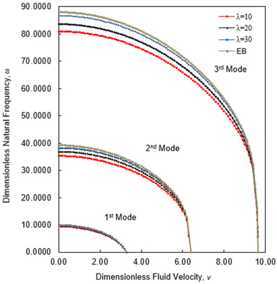
Figure 7.
Fluid velocity vs. natural frequency .
As seen in Figure 7, the slenderness ratio provides a relatively small effect on the first natural frequency but provides a great deal of variation for the second and third natural frequencies. The Rayleigh pipe tends to behave like the Euler–Bernoulli (EB) pipe as the values increase. And for all cases, slenderness ratio does not change the critical velocities, which are caused by the instability of the system. Figure 8 shows variation in the initial three natural frequencies for the Rayleigh pipe with three different values of slenderness ratio and Euler–Bernoulli (EB) pipe.
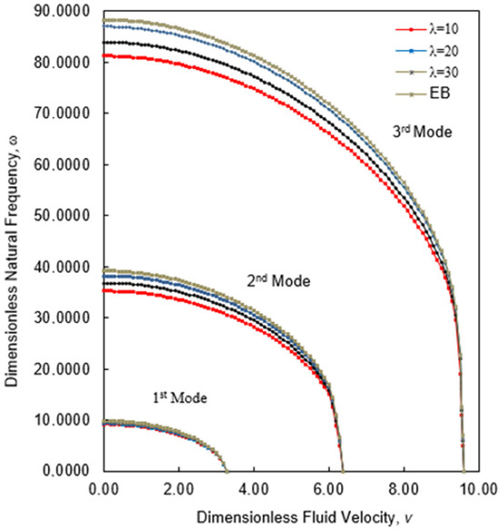
Figure 8.
Fluid velocity vs. natural frequency .
As expected, the slenderness ratio gives much change for the second and third modes. However, including the two concentrated masses into the analysis leads to a higher change in the first natural frequencies. The maximum ratio between natural frequencies with one and two added masses are 86.59 and 82.96% for the first mode, respectively.
The variation in the first natural frequencies due to the different values of concentrated mass ratio is given by Figure 9.
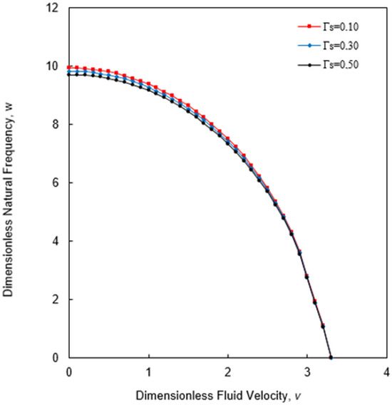
Figure 9.
The natural frequencies for different concentrated mass ratios .
As seen in Figure 9, the natural frequencies between three cases are not very different to each other. The change in the slenderness ratio gives much variation in the natural frequency than concentrated mass ratio. While the added mass ratio increases, the natural frequency decreases.
Displacements are determined by GM and two-way FSI technique due to the mode shapes for the first three modes. The results are normalized and presented comparatively by Figure 10 for the case of having two concentrated masses.
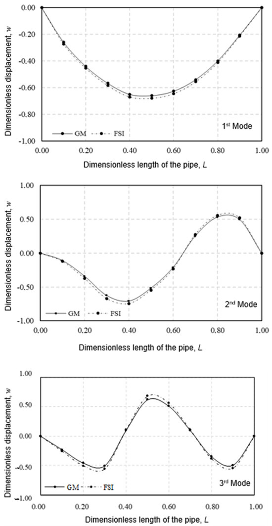
Figure 10.
The distribution of normalized mode shape functions .
There are some basic differences in calculation processes in both methods, and therefore the numerical solution also varies. However, these results, as seen in Figure 10, indicate that there is not a significant deviation between the values of displacements. As the influence of the concentrated mass increases, the symmetry in the mode shape progressively deteriorates, leading to a widening error band between the two methods, with small variations observed within the 0.48–1.39% error range.
5. Conclusions
This study investigates the dynamic behavior of a pipe system using Rayleigh beam theory, which refines the classical Euler–Bernoulli beam theory by factoring in the rotational inertia of the cross-section. This improvement enhances the accuracy of the model, especially for slender structures. The mathematical modeling of the pipe system, incorporating concentrated masses, is developed through two primary techniques: the GM and two-way FSI technique. The analysis shows that as the slenderness ratio increases, the natural frequency also increases. However, when the slenderness ratio becomes large, the rotary inertia factor (1 − β)/λ² approaches one, leading the Rayleigh beam equation to approximate the Euler–Bernoulli beam equation, indicating a diminished impact of rotational inertia for very slender pipes. In contrast, concentrated masses tend to reduce the natural frequencies of the Rayleigh pipe system. The location of the concentrated mass significantly alters the natural frequency, with a more substantial impact as the concentrated mass ratio increases, particularly when the mass is closer to the midspan of the pipe. The accuracy of the GM and two-way FSI technique is confirmed in this study, with both methods demonstrating the crucial effect of concentrated masses and structural parameters on the dynamic behavior of fluid-conveying pipes. The larger discrepancies in higher-order modes have been attributed to their increased sensitivity to numerical discretization and boundary condition approximations. As the influence of the concentrated mass increases, the symmetry in the mode shape progressively deteriorates, leading to a widening error band between the two methods, with small variations observed within the 0.48–1.39% error range. Moreover, the natural frequencies decrease with an increasing number of concentrated masses, especially when the symmetry is disrupted.
By employing Rayleigh beam theory, this study provides a more reliable model for pipe vibration analysis. The theory offers an effective way to analyze the slenderness effects in dynamically weaker systems influenced by concentrated masses. Furthermore, the rotary inertia factor plays a critical role in higher mode shapes, emphasizing its importance in capturing the dynamic response of pipes subjected to high-frequency vibrations. Concentrated masses generally lower the natural frequencies of the pipe, and their effect becomes more pronounced as the concentrated mass ratio increases. As the effect of the concentrated mass increases, the symmetry in the mode shape begins to deteriorate, leading to a shift in modal characteristics.
The reliability of both the GM- and two-way FSI technique-based approaches has been validated, showing their effectiveness in capturing the complex dynamic behavior of pipes conveying fluid. The findings underscore the significant role of concentrated masses and pipe structural properties in influencing system dynamics. In offshore oil and gas pipelines, it is recommended that concentrated masses (e.g., flowmeters, valves) be positioned in such a way that the symmetry of the design is maintained, thereby enhancing stability and reducing resonance risks. These results provide essential insights into the design and optimization of fluid-conveying pipelines, ensuring the structural integrity and performance of these systems in various engineering applications. Moreover, Rayleigh beam theory proves to be a versatile and robust tool for analyzing pipe dynamics under different conditions, making it highly applicable to industries such as offshore, aerospace, and civil engineering, where dynamic loads are a critical factor.
Funding
This research received no external funding.
Data Availability Statement
Data are contained within the paper.
Conflicts of Interest
The author declares no conflicts of interest.
Nomenclature
| Symbol | Description | SI Unit |
| L | Length of the pipe | m (meter) |
| D | Outer diameter of the pipe | m (meter) |
| t | Thickness of the pipe | m (meter) |
| ρs | Density of the pipe material | kg/m3 |
| ρf | Density of the fluid inside the pipe | kg/m3 |
| m | Mass per unit length of the pipe | kg/m |
| M | Concentrated mass | kg (kilogram) |
| E | Young’s modulus | Pa (Pascal) |
| J | Second moment of area | m4 |
| A | Cross-sectional area of the pipe | m2 |
| v | Transverse displacement | m (meter) |
| ω | Natural frequency | rad/s |
| μ | Mass ratio | dimensionless |
| λ | Slenderness ratio | dimensionless |
| U | Fluid velocity | m/s |
| F | External force | N (Newton) |
References
- Ibrahim, R.A. Overview of mechanics of pipes conveying fluids—Part I: Fundamental studies. J. Press. Vessel. Technol. 2010, 132, 034001. [Google Scholar] [CrossRef]
- Hoppmann, W.H. Forced lateral vibration of beam carrying a concentrated mass. J. Applıed Mech. Trans. ASME 1952, 19, 301–307. [Google Scholar] [CrossRef]
- Maltbaek, J. The influence of a concentrated mass on the free vibrations of a uniform beam. Int. J. Mech. Sci. 1961, 3, 197–218. [Google Scholar] [CrossRef]
- Chen, Y. On the vibration of beams or rods carrying a concentrated mass. J. Appl. Mech. 1963, 30, 310–311. [Google Scholar] [CrossRef]
- Pan, H.H. Transverse vibration of an Euler beam carrying a system of heavy bodies. J. Appl. Mech. 1965, 32, 434–437. [Google Scholar] [CrossRef]
- Sato, K.; Saito, H.; Otomi, K. The parametric response of a horizontal beam carrying a concentrated mass under gravity. J. Appl. Mech. 1978, 45, 643–648. [Google Scholar] [CrossRef]
- Kang, M.G. Effect of rotary inertia of concentrated masses on the natural vibration of fluid conveying pipes. J. Korean Nucl. Soc. 1999, 31, 202–213. [Google Scholar]
- Dagli, B.Y.; Ergut, A.; Çiftçioğlu, A.Ö. Estimation of natural frequencies of pipe–fluid–mass system by using causal discovery algorithm. Arab. J. Sci. Eng. 2023, 48, 11713–11726. [Google Scholar] [CrossRef]
- Kang, M.-G. The influence of rotary inertia of concentrated masses on the natural vibrations of a clamped–supported pipe conveying fluid. Nucl. Eng. Des. 2000, 196, 281–292. [Google Scholar] [CrossRef]
- Ghayesh, M.H.; Amabili, M.; Païdoussis, M.P. Thermo-mechanical phase-shift determination in Coriolis mass-flowmeters with added masses. J. Fluids Struct. 2012, 34, 1–13. [Google Scholar] [CrossRef]
- Varol, B.Y.; Sinir, G.B. The Dynamıc Analysis of a Pıpe with Concentrated Masses. In International Symposium on Computing in Science & Engineering Proceedings; GEDIZ University: Izmir, Turkey, 2013; p. 235. [Google Scholar]
- Goyder, H. An experimental ınvestigation of added mass and damping in submerged pipework. In Proceedings of the ASME 2015 Pressure Vessels and Piping Conference, Boston, MA, USA, 19–23 July 2015; American Society of Mechanical Engineers: New York, NY, USA, 2015. Volume V004T04A031. [Google Scholar]
- Zhang, T.; Ouyang, H.; Zhang, Y.; Lv, B. Nonlinear dynamics of straight fluid-conveying pipes with general boundary conditions and additional springs and masses. Appl. Math. Model. 2016, 40, 7880–7900. [Google Scholar] [CrossRef]
- Wang, L.; Yang, J.; Li, Y.H. Nonlinear vibration of a deploying laminated Rayleigh beam with a spinning motion in hygrothermal environment. Eng. Comput. 2021, 37, 3825–3841. [Google Scholar] [CrossRef]
- Tang, Y.; Zhang, H.-J.; Chen, L.-Q.; Ding, Q.; Gao, Q.; Yang, T. Recent progress on dynamics and control of pipes conveying fluid. Nonlinear Dyn. 2024. [Google Scholar] [CrossRef]
- Han, S.M.; Benaroya, H.; Wei, T. Dynamics of transversely vibrating beams using four engineering theories. J. Sound Vib. 1999, 225, 1999–2257. [Google Scholar] [CrossRef]
- ANSYS. Fluent Users Guide; ANSYS: Canonsburg, PA, USA, 2013. [Google Scholar]
- Chang, J.R.; Lin, W.J.; Huang, C.J.; Choi, S.T. Vibration and stability of an axially moving Rayleigh beam. Appl. Math. Model. 2010, 34, 1482–1497. [Google Scholar] [CrossRef]
- Sınır, B.G. The mathematical modeling of vibrations in marine pipelines. Ph.D. Thesis, DEÜ Institute of Science, Warsaw, Poland, 2004. [Google Scholar]
- Sınır, B.G.; Demïr, D.D. The analysis of nonlinear vibrations of a pipe conveying an ideal fluid. Eur. J. Mech. B/Fluids 2015, 52, 38–44. [Google Scholar] [CrossRef]
- Li, B.; Fang, H.; Yang, K.; He, H.; Tan, P.; Wang, F. Mechanical response and parametric sensitivity analyses of a drainage pipe under multiphysical coupling conditions. Complexity 2019, 2019, 3635621. [Google Scholar] [CrossRef]
- Wahrhaftig, A.d.M.; da Silva, M.A.; Brasil, R.M.L.R.F. Analytical determination of the vibration frequencies and buckling loads of slender reinforced concrete towers. Lat. Am. J. Solids Struct. 2019, 16, e196. [Google Scholar] [CrossRef]
- Wahrhaftig, A.d.M.; Magalhães, K.M.M.; Brasil, R.M.L.R.F.; Murawski, K. Evaluation of mathematical solutions for the determination of buckling of columns under self-weight. J. Vib. Eng. Technol. 2021, 9, 733–749. [Google Scholar] [CrossRef]
- Wahrhaftig, A.d.M.; Magalhães, K.M.; Silva, M.A.; Brasil, R.M.d.F.; Banerjee, J.R. Buckling and free vibration analysis of non-prismatic columns using optimized shape functions and Rayleigh method. Eur. J. Mech. A/Solids 2022, 94, 104543. [Google Scholar] [CrossRef]
- De Macêdo Wahrhaftig, A.; da Fonseca, R.M.L.R. Representative experimental and computational analysis of the initial resonant frequency of largely deformed cantilevered beams. Int. J. Solids Struct. 2016, 102, 44–55. [Google Scholar] [CrossRef]
- Huang, Y.-M.; Liu, Y.-S.; Li, B.-H.; Li, Y.-J.; Yue, Z.-F. Natural frequency analysis of fluid conveying pipeline with different boundary conditions. Nucl. Eng. Des. 2010, 240, 461–467. [Google Scholar] [CrossRef]
- Bahaadini, R.; Saidi, A.R. Stability analysis of thin-walled spinning reinforced pipes conveying fluid in thermal environment. Eur. J. Mech. A/Solids 2018, 72, 298–309. [Google Scholar] [CrossRef]
- Paidoussis, M.P. Fluid-Structure Interactions, 2nd ed.; Elsevier: Amsterdam, The Netherlands, 2013. [Google Scholar]
- Hill, J.L.; Swanson, C.P. Effects of lumped masses on the stability of fluid conveying tubes. J. Appl. Mech. 1970, 37, 494–497. [Google Scholar] [CrossRef]
- Dagli, B.Y.; Tuskan, Y.; Gökkuş, Ü. Evaluation of offshore wind turbine tower dynamics with numerical analysis. Adv. Civ. Eng. 2018, 2018, 3054851. [Google Scholar] [CrossRef]
- Bozkurt, M.B.; Ergüt, A.; Özkılıç, Y.O. Comparison of Turkish steel building specifications, TS 648 and SDCCSS 2018. Steel Compos. Struct. Int. J. 2022, 45, 513–533. [Google Scholar]
- Wang, E.; Nelson, T. Structural dynamic capabilities of ANSYS. In ANSYS 2002 Conference; Academia: Pittsburg, PA, USA, 2002. [Google Scholar]
- Ahamed, M.F.; Atique, S.; Munshi, M.A.K.; Koiranen, T. A concise description of one way and two way coupling methods for fluid-structure interaction problems. Am. J. Eng. Res. 2017, 6, 86–89. [Google Scholar]
- Stokey, W.F. Vibration of systems having distributed mass and elasticity, Chapter 7. In Shock and Vibration Handbook, 5th ed.; McGraw-Hill Companies Inc.: New York, NY, USA, 2002. [Google Scholar]
- Chunping, X.; Jiao, W.; Shangjun, C.; Guoxi, F. Dynamic response of a slender sandwich pipe with a metallic foam core subjected to low-velocity impact. Compos. Struct. 2023, 310, 116751. [Google Scholar]
Disclaimer/Publisher’s Note: The statements, opinions and data contained in all publications are solely those of the individual author(s) and contributor(s) and not of MDPI and/or the editor(s). MDPI and/or the editor(s) disclaim responsibility for any injury to people or property resulting from any ideas, methods, instructions or products referred to in the content. |
© 2025 by the author. Licensee MDPI, Basel, Switzerland. This article is an open access article distributed under the terms and conditions of the Creative Commons Attribution (CC BY) license (https://creativecommons.org/licenses/by/4.0/).