Abstract
The simulation of seismic wave attenuation and dispersion in a fractured medium and the analysis of the influencing factors have an important guiding role for fracture detection and characterization. In this paper, for the fractured medium saturated with fluid, the finite element numerical simulation method of the Lamé–Navier and Navier–Stokes equations is investigated and compared with the numerical simulation method based on Biot’s equation. Biot’s method is more suitable for simulating fractured media at the mesoscopic scale, whereas for microscopic media, the Lamé–Navier and Navier–Stokes equations demonstrate distinct advantages. Meanwhile, the numerical simulation method is employed to analyze the influencing factors of connectivity of symmetrical fractures, effective compression length of seismic waves, and fluid viscosity. This analysis further elucidates the mechanisms and change characteristics of seismic wave attenuation and dispersion, providing theoretical guidance for the detection of fractures and fluids.
1. Introduction
Fracture detection characterization is of great significance in a number of scientific fields such as earth, environmental, and engineering [1,2,3]. When seismic waves propagate through porous or fractured media, the elastic contrast between the pore space and the solid matrix, and between fractures and the background rock, causes significantly larger deformation within the pores and fractures compared to the surrounding matrix. This differential deformation squeezes the contained fluid, inducing fluid flow towards other regions. During this flow, friction inevitably occurs between the moving fluid and the rock matrix or mineral grains. This frictional interaction results in seismic wave energy attenuation and velocity dispersion [4]. Consequently, the seismic response depends not only on the rock’s physical properties, but also critically on the distribution of fractures and fluids. Therefore, numerical simulation and analysis of dispersion and attenuation mechanisms in fractured media, along with their influencing factors, play a vital role in guiding the seismic detection and characterization of fractures and subsurface fluids. Therefore, the seismic response not only depends on the medium rock’s physical properties but is also closely related to the distribution of the fracture and fluid. Fractured media dispersion, attenuation of the mechanism‘s numerical simulation, and analysis of influencing factors have an important role in guiding the seismic detection and characterization of fractures and fluid.
Numerous theoretical rock physics models have been developed to characterize the elastic and related seismic responses of fluid-saturated rock with mesoscopic fractures. Galvin and Gurevich [5] and Guo et al. [6,7] established models addressing fluid flow effects between fractures and background pores (FB-WIFF) [8,9]. Guo and Gurevich [10,11] characterized the coupled effects of elastic scattering (ES) and FB-WIFF. By 2022, Guo et al. [12,13] comprehensively investigated the interplay of fluid flow between intersecting fractures, FB-WIFF and ES. Subsequent studies by Li et al. [14] and Wang et al. [15] developed mathematical models incorporating squirt flow in microcracks, FB-WIFF, and ES. Earlier, Sharma introduced an inhomogeneity parameter to describe wave inhomogeneity while analyzing reflected energy partitioning in gas–liquid biphasic saturated media [16]. Building upon this foundation, Kumari and Kumar conducted a systematic numerical investigation into how key microstructural attributes—specifically the inhomogeneity parameter, crack radius, crack density, and local fluid flow (LFF)—govern the reflection characteristics of inhomogeneous waves in porous media permeated with coin-shaped fractures. This study provides critical insights into the interplay between wave physics and fracture geometry [17]. Later, Kumari further investigated WIFF effects in such media using the Biot–Rayleigh framework. [18,19]. However, these mathematical models rarely yield analytical solutions. In such cases, obtaining numerical solutions through wavefield forward modeling becomes an effective approach for analyzing these models.
Numerical simulations serve as a robust validation tool for wave-theoretical predictions while demonstrating superior adaptability to media with elevated structural complexity. Picotti et al. employed an iteratively decomposed 2D finite element algorithm to simulate a decay mechanism by solving the Biot equations of motion [20]. Similarly, Rubino et al. proposed an iterative regionally decomposed finite element method to simulate the amplification effects in alternating layers of porous elastic rocks saturated with gas or water [21]. Masson and Pride applied time-varying stresses to the boundary of a mesoscopic heterogeneous sample and determined its effective complex modulus by calculating the mean stress and strain fields through numerical simulations [22,23]. Extensive numerical simulations have been employed to systematically analyze the controlling factors of rock dispersion and attenuation phenomena.
Rubino et al. analyzed the effect of fracture connectivity on the attenuation of longitudinal waves and found that the fracture permeability and the permeability of the background medium affect the eigenfrequencies of the longitudinal wave energy in the high-frequency and low-frequency bands [24,25,26]. Quintal et al., through quasi-static numerical simulations, found that transverse wave attenuation tends to follow a constant attenuation pattern compared to longitudinal wave attenuation in fractured media with a different connectivity [27]. In 2016, Quintal and Rubino et al. coupled the Lamé–Navier equations with the Navier–Stokes (LNS) equations to propose a novel quasi-static hydrodynamics approach for modeling the squirt flow effects at the meso-scale and microscale [28]. Rubino et al. adopted three different oscillatory relaxation tests to solve the frequency-dependent equivalent stiffness matrix by the least-squares method, and derived equations for seismic wave attenuation and phase velocity at different wave incidence angles based on the poroelastic field [29]. Furthermore, in 2017, they found again that the connectivity of fractures can significantly reduce the anisotropy of the phase velocity of seismic waves [30]. In 2019, Cao et al. investigated the stacked fractured model with a stress-shielding effect and the coplanar fractured model, and evaluated the impact of stress interactions on the attenuation and dispersion of seismic waves under different fractured spatial distributions in the two models [31]. In 2021, Tang et al. used the numerical oscillatory compressibility test method based on Biot’s quasi-static poroelasticity equation for the simulation of squirt flow and designed nine porous media models with varying fracture structures [32]. They systematically investigated the influence of microfracture porosity, orientation, and connectivity on the resulting elastic response and seismic wave. He et al. employed a quasi-static finite element numerical method to simulate the effect of fracture connectivity on WIFF characteristics and seismic response features in fractured porous media [33].
To address the issue of seismic wave dispersion and attenuation in fractured media, the authors investigated the finite element numerical simulation method of the LNS equations and compared it with the numerical simulation method based on Biot’s equation, which proved the LNS equations’ stability and applicability. Building on the theoretical advantages of the LNS equations, this study carried out the first systematic investigation on the impact of fracture connectivity, effective compression length influenced by fracture dip angle, and fluid viscosity at different temperatures on the dispersion and attenuation characteristics of fractured media. This work establishes a solid theoretical foundation for predicting and characterizing fractured hydrocarbon reservoirs through their dispersion and attenuation signatures.
2. Numerical Simulation Theory and Comparison
2.1. Effective Medium Biot Theory
The pore elasticity equation in Biot’s theory describes the process of elastic wave propagation in fluid-saturated porous media [34]. Under quasi-static conditions, the inertial component of the equation is neglected, and the Biot consolidation equation is adopted to describe the fluid flow phenomena induced by elastic waves on mesoscopic scales [35]. The traditional Biot theory consists of two main components:
- (1)
- The theory of linear elasticity, which requires a strict linear relationship between stress and strain in the solid matrix;
- (2)
- Darcy’s law, which is used to simulate the flow or diffusion of free fluid within the pores.
The Biot consolidation equation is solved by taking advantage of the finite element method to obtain at each time point in the time series of the following:
- ①
- The fluid pressure p and solid particle displacement , to calculate the stress and strain ;
- ②
- The first-order time derivative of stress–strain to compute the stress–strain rate , ;
- ③
- The average value of the stress–strain rate across the entire rock sample , .
The volume average value of the stress and strain components is calculated as follows [29]. One-dimensional case:
Two-dimensional case:
Three-dimensional case:
Included among these, n is the grid element, N is the total number of grid elements, and L is the length of the one-dimensional numerical rock sample. A is the total area of the two-dimensional numerical rock sample, and V is the total volume of the three-dimensional numerical rock sample.
2.2. LNS Theory for Poroelastic Media
The coupled Lamé–Navier and Navier–Stokes (LNS) equations can be used to describe the laminar flow of a viscous compressible fluid in a pipe embedded in an isotropic, linearly elastic background medium. The coupled set of equations consists of a combination of momentum conservation and the constitutive equations. Its momentum conservation equation is as follows:
where is the stress tensor and is the Nabla operator; can be composed of two parts: the solid corresponding force and the fluid corresponding force:
Equation (8) is the basic idea of coupling the solid and fluid equations when calculating the solid phase and when calculating the fluid phase . The constitutive equations of solids and fluids corresponding to Equation (8) are, respectively,
is the Kronecker operator, and the dots on the symbols denote first-order time derivatives. represent the three directions of the Cartesian coordinate system. Where denotes the strain trace:
λ denotes the Lamé coefficient:
where and are the shear modulus and bulk modulus, respectively. The relationship between the viscosity parameters is as follows:
Among them and are the shear viscosity and bulk viscosity, respectively. Substituting Equations (9) and (10) into Equation (8) yields the complete constitutive equation:
Since there is no viscosity in the solid phase, setting all the viscosity terms in Equation (8) to zero yields a control solid phase of . Similarly, since there is no shear present in the fluid, the shear modulus is set to zero; the control fluid phase can be obtained for .
By controlling the parameters, it is possible to describe both the solid and liquid phase behavior using Equation (8). Using a similar approach to solving the Biot equation, the coupled Lamé–Navier and Navier–Stokes equations are rewritten in the form of Equation (15), which is much simpler compared to the previous Biot equation, and since the one-dimensional case is no longer relevant for the LNS equations, we will only derive the LNS equations for the two- and three-dimensional cases.
where is the quality factor of the equation and is the damping or quality factor. is referred to as the conserved flux of the equation, while represents the source term of the equation, and is the independent variable of the partial differential equation. The independent variable of the equation in the two-dimensional case is , and the independent variable of Equation (15) in the three-dimensional case is ; the source term , the damping coefficient , and the mass coefficient of the partial differential equation, in general, from both can be set to 0. The conserved flux in the two- and three-dimensional cases can be expressed as follows:
2.3. Comparative Analysis of Simulation Methods
Model numerical simulation experiments and comparative analyses were carried out to better assess the differences and adaptability of the equivalent medium Biot theory and the poroelastic medium LNS theory. Using Biot’s equations as a representative case (due to identical numerical treatments), the implementation comprises (i) domain discretization with adaptive mesh refinement, (ii) prescribed boundary constraints, (iii) time-harmonic excitation via pulse sources with specified frequencies, and (iv) post-processing for mean stress fields. First, the Biot equations were reformulated into the following form of Equations (18)–(20) as follows under the ‘General Form PDE’ module in COMSOL Multiphysics 6.1:
Subsequently, mesh discretization was performed. As shown in Figure 1, a two-dimensional square numerical rock sample with a side length of 3.33 cm was used, the center of which was filled with a pair of orthogonal fractures, the long axis of which was 1.25 cm and the short axis of which was 0.004 cm. The numerical stability is ensured by adopting a mesh resolution of at least six elements per wavelength (EPW) or the mesh size (ℎ) must meet the spatial resolution criteria ℎ ≤ λ/n (λ is the wavelength and n is usually taken as 5 to 10). At the fracture intersections, the mesh is locally refined with a resolution of n = 10 to capture geometric singularities. A force of constant size was applied to the top of the model, and solid particle displacement in the direction perpendicular to the model boundary is fixed to zero. In our numerical configuration, the seismic wave is configured to propagate vertically downward. Therefore, the vertical stress and strain are investigated as the principal components of the wave-induced deformation field.
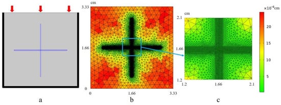
Figure 1.
Porous media model with orthogonal fractures: (a) overall mesh generation of numerical model; (b) the refined mesh at the fracture of the numerical model; (c) local detailed grid.
Using the LNS equations, after solving for the particle displacement of the medium at each point in time by a finite element calculation, the following can occur: (1) The stress and strain over time can be calculated according to Equation (8). (2) Then, the first-order time derivatives, stress rate , and strain rate can be counted. (3) Then, the average stress –strain rate of the whole numerical rock sample at each time point can be calculated. (4) Since the time series used in the simulation is not homogeneous, a non-uniform Fourier transform should be used to combine the and transformed to the frequency domain to obtain and . From this, the P-wave modulus, , and velocity, , can be calculated as follows:
where represents the real part, represents the imaginary part, and is the density of the rock sample.
Since the Biot method treats both the background medium and the fracture as equivalent porous media, whereas the LNS equations treat the background medium and fracture as a non-porous solid phase and a fluid phase, respectively. As a result, after specifying the parameters used by the Biot method, it is necessary to convert the bulk modulus , and the fracture permeability , of the solid particles therein to parameters that can be applied to the LNS theory.
The bulk modulus and shear modulus used in the LNS method are determined through calculations based on the Gassmann equation:
where are the drained bulk modulus and drained shear modulus, respectively, of the porous framework (solid matrix without fluid contribution), is the Biot-Wills coefficient, and is the fluid storage coefficient:
In addition, since the direction of fluid flow in a fracture is parallel to the fracture wall, the permeability of the fracture in the Biot method can be estimated using an analytical solution of the Navier–Stokes equation [36]:
where represents the aperture of the fracture.
Therefore, the parameters used in both methods of Biot’s equation and the LNS equations are shown in Table 1 and Table 2 (adjusted from [28]).

Table 1.
Parameters of Biot’s equation.
Table 2.
Parameters of LNS equations.
In interconnected fractures, the propagation of seismic waves induces a fluid flow parallel to the fracture wall, known as squirt flow. This phenomenon can be attributed to two main factors. Firstly, one reason is that due to the difference in stiffness between the fractures and the background medium, disparate displacements occur when subjected to seismic wave compression. The displacement of the fractures wall is significantly larger than that of the background medium skeleton, resulting in higher fluid pressure within the fractures compared to the surrounding medium. This initiates fluid flow from the fractures into the background pores, thereby designated as the FB-WIFF mechanism. Secondly, in the case of interconnected fractures, compressional wave loading causes spatial variations in fluid pressure. Consequently, fluid flows from fractures with elevated pressure toward those with reduced pressure, a process termed FF-WIFF.
Figure 2 shows a comparison of the simulations of the two methods, and it is observed that the P-wave attenuation and modulus calculated from Biot’s equation are in the range of 104~107 Hz and are almost the same as those of the LNS method, which indicates that the two methods have good stability and consistency in simulating high-frequency fluid flow. However, since the LNS method assumes that its background medium is a non-porous perfectly elastic body, it cannot simulate the fluid flow between the background medium and the fractures and, thus, cannot calculate the attenuation caused by this flow mechanism, and its calculation results do not show the attenuation peaks at low frequencies. It is precisely this characteristic of the LNS method that enables it to exclude the interference of the FB-WIFF, and switch to the FF-WIFF to carry out a separate analysis. A comparison of the two simulations shows that the Biot method is suitable for the simulation of mesoscopic scale fractured media, but for microscopic media, where the specific structure of fractures and pores is clear, and solids and liquids can no longer be simply replaced by equivalent media, the LNS method can show its advantages.
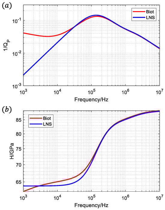
Figure 2.
Comparison of numerical results between Biot method and LNS method: (a) P-wave attenuation ; (b) P-wave modulus ; ‘Biot’ represents creep numerical simulation results based on Biot’s equation; ‘LNS’ represents creep numerical simulation results based on LNS equations.
3. Analysis of Affecting Factors in Attenuation and Dispersion of Fracture Media
3.1. Fracture Connectivity
Fracture connectivity is one of the most important factors affecting seismic dispersion and attenuation. When a seismic wave passes through porous medium containing fractures, it will inevitably cause the flow and diffusion of the saturated fluid within it. However, there may be multiple modes of fluid diffusion, each of which may affect the propagation of seismic waves to different degrees. To study the diffusion mode of fluid in the fractured medium, we set up two numerical models of fractures, the unconnected orthogonal fractures in Figure 3a and the connected orthogonal fractures in Figure 3b, with the side length of the rock samples being 3.33 cm, in which the middle parts of the vertical fractures in Figure 3a are not connected together, whereas the two fractures in Figure 3b vertically intersect in the orthocentric part of the rock samples. The transverse fracture is 2.33 cm long and the aspect ratio is set to 70. In terms of simulation, a simulation method based on the poroelastic medium LNS theory is used to solve the problem, and the relevant boundary conditions are set as in Figure 4, which assumes zero solid displacement normal to the boundary and no fluid flux across it, and its parameters are set as shown in Table 3. Purple lines indicates natural boundary condition.
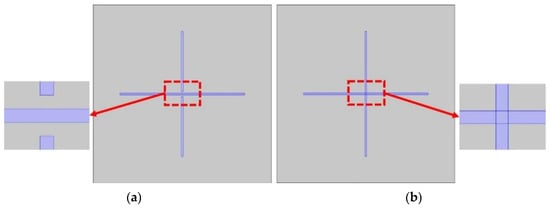
Figure 3.
(a) Unconnected orthogonal fractures; (b) connected orthogonal fractures.
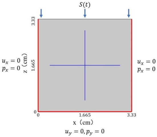
Figure 4.
Boundary conditions diagram.
Table 3.
Rock physics parameters of unconnected and connected orthogonal fractures model.
The fractures and the background medium are fully saturated with water, and their fluid parameters are shown in Table 4. The difference in stiffness between the fractures and the background medium causes a difference in deformation between these two parts, which in turn leads to fluid flow and friction with the rock skeleton particles.
Table 4.
Parameters of fluid in 1D porous media.
As shown in Figure 5a, in terms of seismic wave attenuation, there are two main differences between the connected fractures compared to the unconnected fractures network: (1) High-frequency attenuation due to squirt flow is present. This is due to the flow of fluid into the vertical fractures when the transverse fractures are squeezed by seismic waves; (2) The peak low-frequency attenuation of the connected fractures is much smaller than that of the unconnected fractures due to the permeability and the compressibility of the fractures being much higher than that of the background medium. This is attributed to the combined effect of fractures exhibiting significantly higher permeability and compressibility than the background medium, and the fluid that should flow to the background medium will preferentially flow to the other fracture that is connected, resulting in the weakening of the diffusion of the fluid into the background medium.
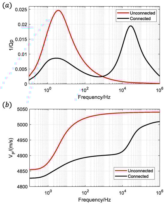
Figure 5.
Connected and unconnected fractures: (a) P-wave attenuation; (b) P-wave velocity.
A comparison of the velocity dispersion in Figure 5b reveals that the connected fracture system has a more pronounced decrease in overall wave velocity relative to the unconnected system. At the beginning of the simulation, the time step is very short, and the fluid in the unconnected fractures can only diffuse into the background medium with lower permeability; the internal fluid pressure is not released in time, so the overall stiffness of the rock samples is stiffer in a short time, and the velocity is larger in the high-frequency band. In contrast, in the connected fractures, the fluid is more likely to diffuse into the fractures with high permeability and low stiffness, and the fluid pressure can reach the equilibrium state in time, resulting in the overall stiffness value of the rock not being high and the velocity being low. With a slow increase in the time step, both models have sufficient time for the internal fluid pressure to reach equilibrium, and the effect of fracture connectivity is subsequently weakened, resulting in the velocities of the two converging in the low-frequency band. Similarly, as the frequency approaches infinity, the fluids in both models have no time to flow and the rocks behave with the same stiffness, so their velocities converge.
3.2. Effective Compression Length of Fractures
The effective compression length of fractures is a primary factor governing the magnitude of seismic dispersion and attenuation. When a seismic wave passes through a fracture, both effective compression and ineffective compression occur, depending on the angle between the wave propagation direction and the fracture plane. When the propagation direction of the seismic wave is perpendicular to the fracture plane or there is an angle not of 0 degrees within the fracture plane, the effective compression on the fracture will lead to significant attenuation and dispersion of seismic wave, and the ineffective compression on the fracture when the propagation direction of seismic wave is parallel to the fracture will have no change or a negligible change on the seismic wave.
The stronger the effective compression of the fractures, the greater the influence of seismic waves by the wave-flow effect. Whether this compression is “effective” or not and the strength of the “effective effect” are closely related to the seismic wave incidence angle. In order to evaluate the compression effect, a new concept of “effective compression length of fractures” is introduced.
where is the angle between the seismic wave propagation direction and main axis of the fractures. Specific information about the is noted in Figure 6.
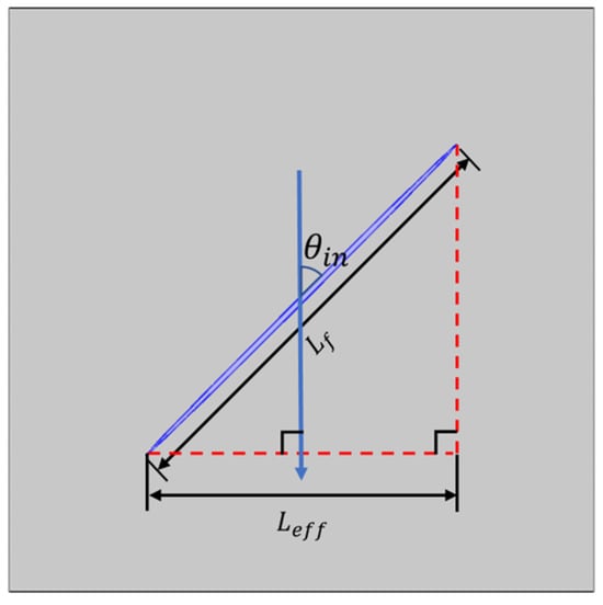
Figure 6.
Effective compression length of single fracture model, in which the blue arrow represents the propagation direction of seismic wave.
As shown in Figure 7a, the P-wave attenuation increases with the increase in the effective compression length, and the P-wave attenuation grows slowly when the effective compression length is small, while the P-wave attenuation increases steeply when the effective compression length is increased to a certain degree, showing a quadratic law. The difference is that the S-wave attenuation value does not keep increasing with the increase in the effective compression length, and the S-wave attenuation value reaches a maximum value at about 0.7, and then gradually decreases. For the P-wave phase velocity, most of the P-wave phase velocity shows the law of decreasing with the increase in the effective compression length, only when the effective compression length is close to one; the P-wave phase velocity increases slightly paradoxically, which may influence of the effective compression length in the direction of the main axis of the non-fracture, i.e., the short axis of this elliptical fracture is ignored. The law of change in the phase velocity of the S-wave with effective compression is similar to the law of change in the S-wave decay; when the effective compression length increases, the S-wave decay value reaches its maximum at about 0.7. Similarly to the behavior of S-wave attenuation, the S-wave phase velocity displays a non-linear relationship with the effective compression length. It initially rises, peaks at a specific value, and then declines as the length continues to increase.
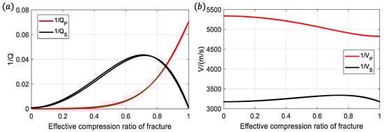
Figure 7.
(a) P-wave and S-wave attenuation varies with fracture’s ECL (effective compressional length); (b) P-wave and S-wave phase velocity varies with fracture’s ECL.
Under constant fracture aperture conditions, an increase in equivalent fracture length reduces the fracture aspect ratio. This geometric adjustment facilitates compressional wave-induced fracture deformation, amplifying fluid pressure variations within fractures and thereby enhancing the WIFF effect. Since the polarization direction of shear waves is perpendicular to their propagation direction, it is evident that at a 45° incidence angle (ECL~0.7), shear waves exert the maximum normal stress on fractures. Consequently, the WIFF effect is the most pronounced under this condition, which is consistent with the findings of Guo [7].
New fluid flow modes are involved in the multi-fracture model, and the effect of effective compression length on seismic waves is more complicated. It is known from the previous analyses that two different fluid flow effects occur when seismic waves pass through intersecting fractured media. The first is the FB-WIFF effect, which arises from fluid flow between the fractures and the background medium. The second is the FF-WIFF effect, whose associated attenuation is positively correlated with the effective compression length of the fractures, so it can be defined as follows:
where is the effective compression length of the fracture dominating the FB-WIFF effect. and are the effective compression lengths of each of the two fractures, respectively, which are geometrically specified, as shown in Figure 8.
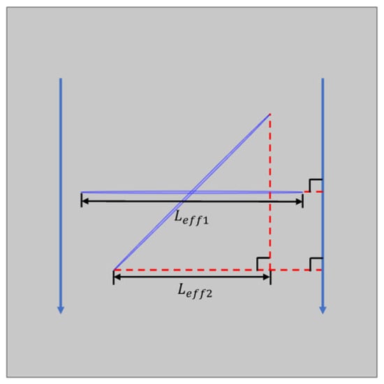
Figure 8.
Effective compression length of the intersecting double-fracture model, in which the blue arrow represents the direction of seismic wave propagation.
Figure 9 illustrates the curves depicting the P-wave and S-wave attenuation and phase velocity as functions of for the double-slit model at a frequency of 4.76 Hz. In Figure 9a, the attenuation of the P-wave gradually increases with the increment of , while the attenuation of the S-wave does not exhibit a strictly monotonically increasing or monotonically decreasing relationship with . However, this also shows that the effect of on the magnitude of P-wave attenuation is very important, which proves that it is as effective as the ineffective compression of seismic waves on fractures. In addition, there is more than one attenuation value corresponding to a particular effective compression length of a fracture in the figure, which is due to the fact that there are two incidence angles of seismic waves from −90 to 90 degrees that can reach the effective compression length of that fracture, and that the two attenuation values corresponding to them are not exactly equal in magnitude is due to the difference in the angle of seismic waves with the overall fracture network.
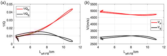
Figure 9.
Variations with : (a) P-wave and S-wave attenuation; (b) P-wave and S-wave phase velocity of double-fracture model under 4.76 Hz.
The other is the FF-WIFF effect of fluid flow from the fracture with higher pressure to the fracture with lower fluid pressure, where the effective compression length of each of the two fractures contributes positively to the magnitude of the fluid pressure inside each of them, and the final determination of the strength of this fluid flow is the difference in fluid pressure between the two fracture interiors. Additionally, the diffusion effect of fluids into the background medium also influences this form of fluid flow, making it unsuitable to describe solely based on the effective compression length of the fractures.
3.3. Viscosity of Fracture-Filling Fluids
The viscosity of fracture-filling fluids is also one of the most important influences on seismic wave dispersion and attenuation. Numerical rock samples of orthogonal fractures shown in Figure 10 were set up, and a simple simulation method of top vertical compression was used. The fracture and background matrix of this numerical model were saturated with glycerol at five different temperatures, 20 °C, 40 °C, 60 °C, 80 °C, and 100 °C, where the fluid viscosity η decreases with increasing temperature T. The fluid parameters are shown in Table 5. The bulk modulus parameters at different temperatures in Table 5 were obtained through experimental measurements, while the viscosity parameters at varying temperatures were derived from the Arrhenius equation and the density parameters across temperature gradients were determined using a linear thermal expansion model.
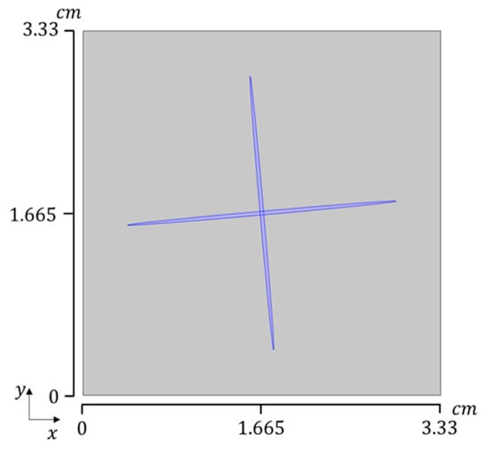
Figure 10.
Porous media model with orthogonal fractures.
Table 5.
Fluid parameters of glycerol with temperature.
Figure 11a of the attenuation versus frequency can be analyzed to show that the numerical simulation produces two attenuation peaks associated with FB-WIFF and FF-WIFF, and both exhibit different eigenfrequencies. With a monotonic increase in temperature, we observe a clear shift of the attenuation eigenfrequencies to higher frequencies for both the low- and high-frequency mechanisms. This contrasts with the stable position of the first attenuation peak and the consistent magnitude of the second. This is due to the fact that an increase in temperature leads to a decrease in the viscosity of glycerol, resulting in an increase in the flow ability of glycerol. The time required for glycerol to flow from the time it is compressed by the seismic wave to the equilibrium of the fluid pressure decreases, and the eigenfrequency of the seismic wave increases accordingly. From the phase–velocity curves at different temperatures in Figure 11b, the viscosity of glycerol decreases with increasing temperature, the inflection point of the velocity dispersion moves toward higher frequencies, and the measurable dispersion of the phase velocity in the seismic band may dominate according to the fluid viscosity of the fractured medium. In addition, the phase velocity of porous media without fluid flow rate limitations at frequencies greater than 106 Hz should also be noted.
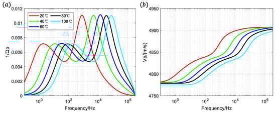
Figure 11.
(a) Attenuation ; and (b) phase velocity of glycerol saturated in orthogonal fracture model at different temperatures.
4. Conclusions
This paper presents numerical simulations on the attenuation and dispersion of fractured media using Biot’s theory of equivalent media and the LNS theory of hole-elastic media. By employing a pair of interconnected fracture models, the fluid flow patterns are analyzed, revealing that the connected fracture model exhibits not only fluid flow from the fracture to the background medium but also fluid flow between interconnected fractures. When the specific spatial structure of the pore or fracture is known, the LNS equations are more suitable than Biot’s equation. Biot’s equation treats all media as equivalent media with certain porosity and permeability, whereas the LNS equations strictly distinguish between solids and fluids. Therefore, the LNS equations provide a more “realistic” approach than Biot’s equation for simulating fluid flow. The compressive effect that seismic waves can produce is related to the propagation direction. When the propagation direction of seismic waves is perpendicular to the main axis of the fracture or there is a small angle, the attenuation and dispersion of seismic waves will increase. The author proposed the concept of the “effective compression length of fractures” to explain this phenomenon. The effect of fluid viscosity on seismic attenuation and dispersion is analyzed by glycerol at different temperatures. With the gradual increase in temperature, the viscosity of glycerol decreases, resulting in an increase in glycerol’s flow ability. From the moment of compression by the seismic wave, the glycerol starts to flow until the time required for the fluid pressure to equilibrate decreases, and the eigenfrequencies of both the low-frequency attenuation and high-frequency attenuation of the seismic wave are shifted to the high-frequency position. Numerical simulation experiments show that the presence of fractures and fluids cause attenuation and dispersion phenomena of elastic parameters in rocks and also make it possible to detect fractures and fluids by seismic waves in fractured media. However, regarding the diversity of fracture and fluid types, the main influencing factors need to be clarified during the actual seismic fluid prediction process, so as to reduce the multiplicity of solutions for seismic fracture and fluid prediction.
Author Contributions
Conceptualization, Z.W. and F.Z.; Data Curation, G.T. and Y.H.; Formal Analysis, Z.W., F.Z., and G.T.; Funding Acquisition, F.Z.; Investigation, Z.W., F.Z., and G.T.; Methodology, Z.W., F.Z., and G.T.; Resources, Z.W. and G.T.; Software, Z.W., F.Z., and G.T.; Validation, Z.W., F.Z., and Y.H.; Writing—Original Draft, Z.W.; Writing—Review and Editing, Z.W., F.Z., G.T., and Y.H. All authors have read and agreed to the published version of the manuscript.
Funding
This research is supported by National Science and Technology Major Project: 2025ZD1404802.
Data Availability Statement
The original contributions presented in this study are included in the article. Further inquiries can be directed to the corresponding author.
Conflicts of Interest
Author Zhentao Wang was employed by the company “Geophysical Research Institute of Shengli Oilfield Branch Co.”, the topic of this paper is fundamental rock physics. No data are dependent on the company, and the research was not funded by it. There are no commercial interests involved.
References
- Bakulin, A.; Grechka, V.; Tsvankin, I. Estimation of fracture parameters from reflection seismic data—Part I: HTI model due to a single fracture set. Geophysics 2000, 65, 1788–1802. [Google Scholar] [CrossRef]
- Liu, E.; Hudson, J.A.; Pointer, T. Equivalent medium representation of fractured rock. J. Geophys. Res. 2000, 105, 2981–3000. [Google Scholar] [CrossRef]
- Maultzsch, S.; Chapman, M.; Liu, E.; Li, X.Y. Modelling frequency-dependent seismic anisotropy in fluid-saturated rock with aligned fractures: Implication of fracture size estimation from anisotropic measurements. Geophys. Prospect. 2003, 51, 381–392. [Google Scholar] [CrossRef]
- Duan, C.X.; Zhang, F.C. Robust seismic attenuation compensation based on generalized minimax concave penalty sparse representation. J. Geophys. Eng. 2023, 20, 1054–1064. [Google Scholar] [CrossRef]
- Galvin, R.J.; Gurevich, B. Effective properties of a poroelastic medium containing a distribution of aligned cracks. J. Geophys. Res. 2009, 114, B07305. [Google Scholar] [CrossRef]
- Guo, J.; Rubino, J.G.; Barbosa, N.D. Seismic dispersion and attenuation in saturated porous rocks with aligned fractures of finite thickness: Theory and numerical simulations-Part 1: P-wave perpendicular to the fracture plane. Geophysics 2018, 83, WA49–WA62. [Google Scholar] [CrossRef]
- Guo, J.; Rubino, J.G.; Barbosa, N.D. Seismic dispersion and attenuation in saturated porous rocks with aligned fractures of finite thickness: Theory and numerical simulations-Part 2: Frequency-dependent anisotropy. Geophysics 2018, 83, WA63–WA71. [Google Scholar] [CrossRef]
- Müller, T.; Gurevich, B. One-dimensional random patchy saturation model for velocity and attenuation in porous rocks. Geophysics 2004, 69, 1166–1172. [Google Scholar] [CrossRef]
- Müller, T.M.; Gurevich, B.; Lebedev, M. Seismic wave attenuation and dispersion resulting from wave-induced flow in porous rocks—A review. Geophysics 2010, 75, 75A147–75A175. [Google Scholar] [CrossRef]
- Guo, J.; Gurevich, B. Effects of coupling between wave-induced fluid flow and elastic scattering on P-wave dispersion and attenuation in rocks with aligned fractures. J. Geophys. Res. Solid Earth 2020, 125, e2019JB018685. [Google Scholar] [CrossRef]
- Guo, J.; Gurevich, B. Frequency-dependent P wave anisotropy due to wave-induced fluid flow and elastic scattering in a fluid-saturated porous medium with aligned fractures. J. Geophys. Res. Solid Earth 2020, 125, e2020JB020320. [Google Scholar] [CrossRef]
- Guo, J.; Zhao, L.; Chen, X. Theoretical modelling of seismic dispersion, attenuation and frequency-dependent anisotropy in a fluid-saturated porous rock with intersecting fractures. Geophys. J. Int. 2022, 230, 580–606. [Google Scholar] [CrossRef]
- Guo, J.; Gurevich, B.; Chen, X. Dynamic SV-wave signatures of fluid-saturated porous rocks containing intersecting fractures. J. Geophys. Res. Solid Earth 2022, 127, e2022JB024745. [Google Scholar] [CrossRef]
- Li, S.Q.; Wang, W.H.; Su, Y.D.; Guo, J.X.; Tang, X.M. P-and SV-wave dispersion and attenuation in saturated microcracked porous rock with aligned penny-shaped fractures. Pet. Sci. 2024, 21, 143–161. [Google Scholar] [CrossRef]
- Wang, W.; Li, S.; Guo, J.; Zhang, C.; Duan, W.; Su, Y.; Tang, X.M. Frequency-dependent elastic properties of fracture-induced VTI rocks in a fluid-saturated porous and microcracked background. Geophysics 2024, 89, MR137–MR153. [Google Scholar] [CrossRef]
- Sharma, M.D.; Kumar, M. Reflection of attenuated waves at the surface of a porous solid saturated with two immiscible viscous fluids. Geophys. J. Int. 2011, 184, 371–384. [Google Scholar] [CrossRef]
- Kumari, M.; Kumar, M. Wave-induced flow of pore fluid in a cracked porous solid containing penny-shaped inclusions. Pet. Sci. 2021, 18, 1390–1408. [Google Scholar] [CrossRef]
- Kumari, M.; Kumar, M. Reflection of inhomogeneous waves at the surface of a cracked porous solid with penny-shaped inclusions. Waves Random Complex Media 2022, 32, 1992–2013. [Google Scholar] [CrossRef]
- Zhang, L.; Ba, J.; Carcione, J.M.; Sun, W. Modeling wave propagation in cracked porous media with penny-shaped inclusions. Geophysics 2019, 84, WA141–WA151. [Google Scholar] [CrossRef]
- Picotti, S.; Carcione, J.; Rubino, J.G.; Santios, J.E. P-wave seismic attenuation by slow-wave diffusion: Numerical experiments in partially saturated rocks. Geophysics 2007, 72, N11–N21. [Google Scholar] [CrossRef]
- Rubino, J.G.; Santos, J.E.; Picotti, S.; José, M.C. Simulation of upscaling effects due to wave-induced fluid flow in biot media using the finite-element method. J. Appl. Geophys. 2007, 62, 193–203. [Google Scholar] [CrossRef]
- Masson, Y.J.; Pride, S.R. Poroelastic finite difference modeling of seismic attenuation and dispersion due to mesoscopic-scale heterogeneity. J. Geophys. Res. Solid Earth 2007, 112, B03204. [Google Scholar] [CrossRef]
- Pride, S.R.; Berryman, J.G.; Harris, J.M. Seismic attenuation due to wave-induced flow. J. Geophys. Res. Solid Earth 2004, 109, B01201. [Google Scholar] [CrossRef]
- Rubino, J.G.; Müller, T.M.; Guarracino, L.; Milani, M.; Holliger, K. Seismoacoustic signatures of fracture connectivity. J. Geophys. Res. Solid Earth 2014, 119, 2252–2271. [Google Scholar] [CrossRef]
- Rubino, J.G.; Milani, M.; Holliger, K.; Tobias, M.; Guarracino, L. Can we use seismic waves to detect hydraulic connectivity between fractures? SEG Technical Program Expanded. Soc. Explor. Geophys. 2014, 2894–2898. [Google Scholar]
- Rubino, J.G.; Quintal, B.; Müller, T.M.; Guarracino, L.; Jänicke, R.; Steeb, H.; Holliger, K. Energy dissipation of P-and S-waves in fluid-saturated rocks: An overview focusing on hydraulically connected fractures. J. Earth Sci. 2015, 26, 785–790. [Google Scholar] [CrossRef]
- Quintal, B.; Jänicke, R.; Rubino, J.G.; Steeb, H.; Holliger, K. Sensitivity of S-wave attenuation to the connectivity of fractures in fluid-saturated rocks. Geophysics 2014, 79, WB15–WB24. [Google Scholar] [CrossRef]
- Quintal, B.; Rubino, J.G.; Caspari, E.; Holliger, K. A simple hydromechanical approach for simulating squirt-type flow. Geophysics 2016, 81, D335–D344. [Google Scholar] [CrossRef]
- Rubino, J.G.; Caspari, E.; Müller, T.M.; Milani, M.; Barbosa, N.D.; Holliger, K. Numerical upscaling in 2-D heterogeneous poroelastic rocks: Anisotropic attenuation and dispersion of seismic waves. J. Geophys. Res. Solid Earth 2016, 121, 6698–6721. [Google Scholar] [CrossRef]
- Barbosa, N.D.; Rubino, J.G.; Caspari, E.; Holliger, K. Sensitivity of seismic attenuation and phase velocity to intrinsic background anisotropy in fractured porous rocks: A numerical study. J. Geophys. Res. 2017, 122, 8181–8199. [Google Scholar] [CrossRef]
- Cao, C.H.; Fu, L.Y.; Ba, J.; Zhang, Y. Frequency- and incident-angle-dependent P-wave properties influenced by dynamic stress interactions in fractured porous media. Geophysics 2019, 84, MR173–MR184. [Google Scholar] [CrossRef]
- Tang, G.; Guo, F.; Wang, S.; Sun, C.; Liu, T.; Dong, C. Effects of porosity, orientation and connectivity of microcracks on dispersion and attenuation of fluid-saturated rocks using an upscaling numerical modelling of the squirt flow mechanism. Explor. Geophys. 2022, 53, 425–438. [Google Scholar] [CrossRef]
- He, Y.X.; He, W.T.; Zhang, M.F.; Zhang, J.L.; Liu, W.H.; Ma, X.Y.; Tang, G.Y.; Wang, S.X.; Li, G.F.; Liu, J.Z.; et al. Sensitivity of seismic attenuation and dispersion to dynamic elastic interactions of connected fractures: Quasi-static finite element modeling study. Pet. Sci. 2023, 20, 177–198. [Google Scholar] [CrossRef]
- Biot, M.A. General Theory of Three-Dimensional Consolidation. J. Appl. Phys. 1941, 12, 155–164. [Google Scholar] [CrossRef]
- Biot, M.A. Mechanics of deformation and acoustic propagation in porous media. J. Appl. Phys. 1962, 28, 179–191. [Google Scholar] [CrossRef]
- Jaeger, J.C.; Cook, N.G.; Zimmerman, R.W. Fundamentals of Rock Mechanics, 4th ed.; Blackwell Publishing: Oxford, UK, 2009. [Google Scholar]
Disclaimer/Publisher’s Note: The statements, opinions and data contained in all publications are solely those of the individual author(s) and contributor(s) and not of MDPI and/or the editor(s). MDPI and/or the editor(s) disclaim responsibility for any injury to people or property resulting from any ideas, methods, instructions or products referred to in the content. |
© 2025 by the authors. Licensee MDPI, Basel, Switzerland. This article is an open access article distributed under the terms and conditions of the Creative Commons Attribution (CC BY) license (https://creativecommons.org/licenses/by/4.0/).