Abstract
To enhance the efficiency and accuracy of partial-to-whole point cloud registration for complex workpieces, this paper presents a novel method based on the Mean Feature Descriptor (MFD). The proposed approach extracts geometric features from key points in the scanned point cloud, constructs local feature descriptors using a localized coordinate system, and performs coarse registration. Compared to conventional local descriptor-based methods, the MFD algorithm not only effectively captures local geometric characteristics but also significantly improves computational efficiency while maintaining high registration accuracy. Experimental results demonstrate that the MFD-based method substantially accelerates registration and measurement processes for complex workpieces. It exhibits strong robustness against noise and varying point cloud resolutions, outperforming existing descriptors such as PFH, FPFH, and HoPPF in terms of F1 score and matching precision. The method achieves reliable registration even under challenging conditions, such as partial overlap and geometric feature sparsity. Notably, the MFD descriptor inherently captures geometric symmetry-invariant features of local point cloud regions especially symmetric interfaces of complex workpieces. This ensures stable registration performance even when partial scans only preserve part of the workpiece’s symmetric structure.
1. Introduction
3D laser scanning technology has developed rapidly. Due to its non-contact and high-precision characteristics, it has been widely applied in surface measurement, model digitization, and other fields [1]. This technology overcomes the limitations of traditional measurement methods in terms of accuracy and efficiency, enabling rapid and automated data collection of the object’s surface morphology. The point cloud data obtained achieves sub-millimeter precision and can accurately reflect the shape of the object’s surface. Point cloud registration is the process of solving the rigid transformation matrix between two corresponding point clouds, aligning them into the same reference coordinate system. During the processing of point cloud data, point cloud registration technology is often used for point cloud data stitching and coordinating system transformation. Its application in the field of intelligent manufacturing is also becoming more widespread [2,3]. Current registration technologies mostly focus on situations where the target point cloud and the point cloud to be registered share the same features, meaning the two sets of point cloud data are identical in shape and the features they contain, with only differences in point cloud density and noise [4,5]. However, in practical industrial scanning, the two datasets are often not exactly identical. One typical reason is different capture angles. Due to large workpiece size limitations, the point cloud to be registered is usually scanned from a local, specific angle. Meanwhile, the target point cloud based on CAD covers the workpiece from a comprehensive angle, leading to differences in feature visibility and local geometric perspective.
In industrial production scenarios, point cloud registration often encounters significant differences between the target point cloud and the point cloud to be registered. Taking the production process of a large product as an example, the manufacturing deviations of the workpiece can have a significant impact on the precision assembly process. In order to obtain the deviation of key dimensions and evaluate the part manufacturing errors, 3D scanning of the key features of the workpiece and dimension evaluation are the most commonly used methods in automated production processes. By using non-contact laser scanning equipment, the real surface point cloud of the workpiece can be quickly acquired. After the point cloud data undergoes coordinate transformation, the scanned point cloud data is registered with the CAD point cloud data of the design model. This allows for the extraction of the real workpiece’s feature dimensions in the known CAD coordinate system, completing the workpiece’s dimensional inspection. However, for large-sized workpieces, a full scan of the workpiece’s surface requires more measurement time, resulting in larger point cloud data that is difficult to process. For workpiece dimensional inspection aimed at precision assembly, only the dimensional deviations of the workpiece mating features need to meet the assembly requirements. Therefore, scanning and point cloud registration of the local assembly features of the workpiece and performing key dimension evaluation plays a crucial role in improving production efficiency. In this process, point cloud registration is the most critical step in the coordinate transformation of the 3D scanned point cloud data. The point cloud to be registered is the measured point cloud data obtained through 3D scanning, while the target point cloud is the discrete point cloud form of the ideal CAD model of the entire workpiece. For measurement efficiency, the measured point cloud usually only includes the key positions of the workpiece that need to be evaluated, making it a subset of the target point cloud. This type of registration, where the point cloud to be registered and the target point cloud differ in features, is called partial overlapping point cloud registration.
The most commonly used method in point cloud registration is the Iterative Closest Point (ICP) algorithm, proposed by Besl et al. [6] in 1992. This algorithm matches the closest points in the point clouds to be registered and the target point cloud, iteratively transforming them to minimize the sum of distances between all matched point pairs, thus achieving point cloud registration. The ICP algorithm and its improvements are highly sensitive to the initial registration, making it prone to falling into local minimum. This is because the optimization objective function of ICP is non-convex. Consequently, the function has multiple local minima and cannot perceive the direction of the global optimum. Meanwhile, ICP does not incorporate global or robust local features to constrain the initial transformation, and lacks sufficient global geometric information to guide the search for corresponding points in the initial stage. This further amplifies the risk of falling into local optima. Therefore, a rough registration is usually required before applying the ICP algorithm to obtain a good initial value and solve for the global optimum more quickly.
During the coarse registration of point clouds, local feature descriptors play an important role. Feature descriptions can extract key information about the surface shape from the point cloud, playing a crucial role in point cloud registration and 3D target recognition. Feature descriptors include global and local feature descriptors. Global feature descriptors are constructed based on the overall characteristics of the point cloud data, with a higher consistency requirement between the two point clouds being registered. Compared to global feature descriptors, local feature descriptors use a series of geometric features and the spatial distribution of local surfaces to generate differentiated vector representations, which allow similar points to have similar vector representations and provide stronger robustness to interference such as noise and occlusion [7,8,9].
In point cloud registration methods based on local features, Rusu [10,11] et al. proposed the Point Feature Histogram (PFH), Fast PFH (FPFH), and Tombari [12] et al. proposed the Signature of Histograms of Orientations (SHOT). These methods achieve local feature descriptions of points by establishing local coordinate systems or describing the relative relationships between a point and its neighboring points. Zhao [13] et al. and Wu [14] et al. improved the local coordinate system establishment methods based on the aforementioned local feature descriptors, adding local point pair distribution or transformation information within the region. They proposed the more robust Histograms of Point Pair Features (HoPPF) and Point Pair Transformation Feature Histograms (PPTFH). Logoglu [15] et al. proposed the Spatial Concentric Surflet-Pair (SPAIR) descriptor, which divides the spherical neighborhood of a key point into regions and establishes feature histograms for different areas, enhancing the robustness of the descriptor by combining partial spatial information. The point cloud registration methods based on such local descriptors are referred to as local feature-based point cloud registration methods [16,17,18]. Shah [17] et al. combined feature histograms and Random Sample Consensus (RANSAC) to first perform approximate matching of local features, then used bounding box boundary segmentation to select the data that needs to be considered for further registration in the global data. However, this method does not provide precise registration results, and the point pair matching computation time is long, significantly limiting registration efficiency.
Inspired by traditional point cloud registration methods, many techniques construct deep convolutional networks as key point detectors or local feature descriptors for point clouds. Deep Closest Point (DCP) [19] and Deep Virtual Corresponding Points (DeepVCP) [20] use weighted confidence and point positions to calculate relative poses. PR Net [21], based on DCP, uses an actor–critic model and global point aggregation features to obtain global features. DGR [22] uses weighted SVD to solve for rigid transformations after selecting point pairs based on confidence and retaining confidence as weights. Li [18] et al. proposed a new key point matching algorithm based on deep learning, improving the robustness of the local feature-based matching registration method and achieving the registration of partial and whole point clouds. For partial overlapping point cloud data, Sarode [23] et al. proposed a fully convolutional neural network MaskNet, which performs internal estimation based on the PointNet structure. By calculating a mask, it identifies which points in the target point cloud are internal, “masking” abnormal regions to protect them from the influence of the target point cloud. Shotton et al. [24] proposed the Overlap Mask Network (OMNet), where in each iteration of the network, it predicts the overlap masks of the two input point clouds. With a precise overlap mask, non-overlapping points are rejected during global feature aggregation. However, these methods require a large amount of data for training the neural networks, which results in high computational costs or is only applicable to scenarios or objects with a small amount of data. For registration scenarios such as complex workpieces with a large number of point clouds and unclear feature differences, deep neural networks and other methods often encounter registration errors.
Since local descriptors need to provide accurate descriptions, noise robustness, and real-time processing capability, they are very useful in practical applications. Therefore, this paper aims to achieve the registration of partial point clouds with the whole point cloud for workpieces. Most complex workpieces cabin assembly interfaces possess inherent geometric symmetry. Exploiting symmetry-invariant features can reduce the impact of partial scanning on feature matching. It proposes a partial point cloud and whole point cloud registration method based on the Mean Feature Descriptor (MFD). This method describes the geometric relationship between key points and centroid points in partitioned neighborhoods to achieve matching of local features and complete the registration of partial point clouds with the whole point cloud. The method proposed in this paper can provide highly reliable and efficient technical solutions for core links such as complex workpiece inspection and assembly positioning.
2. Mean Feature Descriptor
To address the issues of ICP’s sensitivity to initial registration and its tendency to fall into local optima, this paper proposes a two-stage framework of MFD coarse registration combine ICP fine registration by conducting robust local feature modeling and global initial transformation calculation. The strong discriminability of the MFD descriptor can ensure the correctness of initial corresponding points. Meanwhile, the global initial transformation performed via SVD can provide the optimal initial value for ICP.
2.1. Method Architecture
In this paper, the partial point cloud is taken as the point cloud to be registered, and the whole point cloud is the target point cloud. The geometric information contained in the partial point cloud is entirely included in the whole point cloud. The point cloud registration process consists of two steps: point cloud preprocessing and coarse registration. The flowchart of the proposed MFD method is shown in Figure 1.
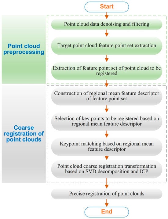
Figure 1.
The flowchart of the registration method for differentiated point cloud data.
- (1)
- Denoising filter operation
For the large amount of point cloud data obtained from high-precision 3D scanning, optimizing the scanning environment to reduce noise is necessary. Firstly, scanning is performed in a dark room to avoid ambient light interference. Meanwhile, the scanning system should be placed on a stable platform to minimize vibration-induced noise. These measures align with noise limitation requirements and reduce the generation of scattered noise and outlier cluster noise points. Then, a denoising filter operation is performed. The initial point cloud collected by the 3D scanning device is a collection of usable points and noise points. Due to the presence of noise points, which can affect the accuracy of point cloud registration, denoising is necessary. Noise points originate from the system errors of the 3D scanning system itself and environmental influences during data collection. They can generally be classified into scattered noise points, outlier cluster noise points, internal duplicate points, and redundant noise points. The core of the point cloud denoising method is to construct a mathematical function based on the distribution characteristics of the noise points. It filters and records the noise points and removes them accordingly. During the denoising process of point cloud data preprocessing, statistical filtering and radius filtering are used to remove scattered noise and isolated outlier noise points.
High-resolution 3D scanning devices capture densely packed data points. While the vast number of data points can accurately express the shape information of the object’s surface, they also significantly limit the processing speed of point cloud data. Therefore, point cloud data can be simplified based on the degree of feature information in the point cloud.
By creating a covariance matrix from the neighboring points k of the point cloud, Principal Component Analysis (PCA) is used to compute the normal information of the point cloud. To clarify the direction of the point cloud’s normal vector, the normal direction is redirected based on the direction of the mean neighborhood points of the point cloud.
For a given point pi and its k neighboring points , the mean neighborhood point is calculated as
The normal vector ni of the point Pi is defined as
Using the normal vector information, the point feature degree is calculated for the extraction of key points from the point cloud, thereby reducing the redundancy of the point cloud model. The feature degree of point Pi is calculated as
where ni1~nik correspond to the normal vectors of the k neighboring points pi1~pik of Pi point. The mean feature degree of the point cloud is then calculated as
Points with a feature degree smaller than the mean feature degree of the point cloud are marked as feature points of the point cloud, resulting in the feature point set P0 of the point cloud.
- (2)
- Coarse registration of the point cloud
A local feature descriptor for the point cloud is established to describe the geometric information of a point within its neighborhood. A point in the point cloud is selected as a key point. Based on the position relationship between the key point and the centroid of its neighborhood, a local coordinate system is established. The point data within the neighborhood is divided into regions, and the centroid of each partition is computed and encoded accordingly. Then, the key point and the centroid points of the divided regions are used to construct local coordinate systems. Based on the relative position relationship between the key point and the region centroids, as well as the normal vector information, the MFD is constructed.
First, by evaluating the similarity of the MFDs of the feature point set in the point cloud to be registered, points corresponding to MFDs with distinct geometric properties are selected as the key points for registration in the point cloud to be registered. Then, in the target point cloud, points that have similar regional feature descriptions to the key points in the point cloud to be registered are searched and matched as target key points. The degree of matching is measured by the ratio of the second nearest distance to the nearest distance. Finally, key point pairs with a high matching degree are selected. The initial registration is completed based on the position transformation relationship of the key point pairs using a Singular Value Decomposition (SVD)-based coordinate system transformation method.
- (3)
- Fine registration of the point cloud
The ICP algorithm and its improved versions [25,26,27] are used to further complete the position registration of the feature point sets between the point cloud to be registered and the target point cloud. Finally, the ICP algorithm is applied to complete the fine registration of the entire point cloud.
2.2. Feature Point Extraction
First, it is necessary to extract representative feature points from the point cloud. These feature points are typically those with distinct geometric properties in the point cloud, and they can be selected based on changes in the point cloud’s normal vectors. Each point in the point cloud can have its normal vector ni calculated, which reflects the orientation of the local surface at that point. In the point cloud, changes in normal vectors often indicate significant changes in the surface geometry. Therefore, feature points are selected at locations where the normal vector changes sharply. For a given point cloud P, the normal vectors are calculated as follows:
where Ni is the set of neighboring points of point , and ni is the normal vector of point Pi.
The selection of feature points typically depends on changes in the normal vectors and the geometric shape of the point cloud. Areas in the point cloud where the normal vector changes significantly usually correspond to regions with high curvature or places where the surface undergoes notable changes. By analyzing the gradient of the normal vector changes, the following is obtained:
When there is a large change in the normal vector, it indicates that the surface around that point has strong geometric features, making it suitable to be selected as a feature point, as shown in Figure 2. Based on this, a normal vector change gradient threshold Δnthreshis set to filter out points with distinct geometric properties. The threshold Δnthreshis is determined by the statistical distribution of Δni across the entire point cloud. In this paper, the 75th percentile of all Δni values is used. Only points with a normal vector change gradient of Δni > Δnthreshis, i.e., points with sharp normal vector changes are retained as feature points with distinct geometric properties.
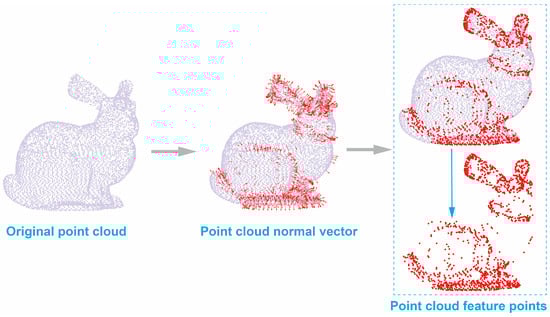
Figure 2.
Extraction of feature points from the point cloud.
Through the above normal vector analysis, the final set of feature points P0 is selected from the point cloud P.
2.3. Construction of MFD
Constructing Local Feature Descriptors for Point Clouds. The goal is to provide a mathematical expression of the local features in the point cloud that is invariant to the coordinate system of the point cloud. This expression has the property of rigid transformation invariance, allowing it to describe the local features of the point cloud. To characterize the geometric features of a point in the feature point set within its r-neighborhood, a MFD is proposed. This descriptor represents the geometric characteristics of the point’s r-neighborhood by describing the geometric location attributes of the centroids of the partitioned neighboring points within the r-neighborhood. Using the centroid point information of the neighborhood of the key point to represent its local geometric information helps reduce the computational workload for constructing the descriptor, mitigate the impact of noise and point cloud resolution on the descriptor, and improve its robustness. For a point in the point set , all neighboring points within its r-neighborhood are taken:
The neighborhood of point is defined as shown in Figure 3a. Based on the established local coordinate system, the r-neighborhood of is divided into eight non-overlapping regions using the positive and negative directions of the X, Y, and Z axes. The positive and negative directions of the X-axis, Y-axis, and Z-axis are used to encode these eight regions as one through eight. Figure 3b shows the centroids of these eight neighborhood partitions.
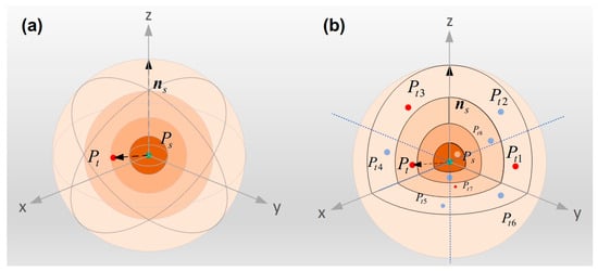
Figure 3.
Neighborhood of Point Ps. (a) Partition of the neighborhood of point Ps; (b) key points in the neighborhood.
The centroid Pt of the set of neighboring points is calculated as formula (10).
The neighborhood coordinate system is defined using the normal vector information of point pairs and . Figure 4 shows the method for establishing a local coordinate system. The normal vector direction of point is chosen as the Z-axis. The line connecting point and point , along with the normal vector of point , defines a plane, and the perpendicular direction to this plane is the -axis. The -axis is then determined based on the standard Cartesian coordinate system rules.
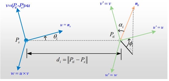
Figure 4.
Establishment of local coordinate system.
According to Figure 4, local coordinate systems are established using points and to form eight different local coordinate systems.
where u, v, and w represent the three coordinate axes of the local coordinate system; represents the normal vector of point ; and d represents the distance between points and .
According to the local coordinate system, the local feature description vector of point and point can be expressed as , which contains 4 elements that describe the angle relationship between the normal direction of the point cloud and the local coordinate system and the Euclidean distance between the two points. The formula is
where represents the normal vector of point .
Based on the local coordinate systems constructed using the key point and its eight neighborhood region centroids , eight sets of local feature descriptor vectors between the key point and the centroids of the neighborhood regions are obtained:
The local feature descriptor vectors are arranged according to the neighborhood region encoding, resulting in a final MFD with a dimensionality of 8 × 4 = 32, expressed as
2.4. Key Point Search and Matching
During the registration process of partial and whole point clouds, the whole point cloud may contain features that do not exist in the partial point cloud to be registered. Therefore, it is necessary to select key points with distinct geometric properties from the partial point cloud as the key points for registration. Then, corresponding points in the whole point cloud with similar geometric properties to the key points of the partial point cloud are found as matching target key points, which are then used to compute the transformation relationship between the two point clouds.
Select points with distinct geometric properties from the partial point cloud as the key points for registration: For any two points, and , construct their MFDs and calculate the Euclidean distance between the two descriptors. If , it indicates that the neighborhoods of the two points share similar geometric features. The larger the value of , the greater the geometric feature difference between the neighborhoods of the two points.
During the point cloud preprocessing process, the target point cloud feature point set and the point cloud feature point set to be registered are divided based on point feature degrees, and corresponding MFD sets and are constructed. For each descriptor in the descriptor collection of the feature point region in the point cloud to be registered, we search for neighboring descriptors within the -neighborhood of the descriptor in the set . If the average distance between the neighboring descriptors and the key point descriptor is greater than the threshold , it indicates that the key point in the point cloud to be registered has distinct geometric properties. This point is then selected as a key point to be registered, and a key point matrix for the point cloud to be registered is established.
The point cloud local descriptors are matched using an operator-based matching method based on the ratio of the second nearest distance to the nearest distance. A threshold H is set based on conventional practices in the field of local feature matching. For local feature matching methods, a threshold range of 1.2~1.5 is widely adopted in the industry. For each key point to be registered in the set S, its nearest and second nearest descriptors and are sequentially searched for in the set . The ratio of the distances between the two descriptors and the key point descriptor is then calculated.
The point cloud local descriptors are matched using an operator-based matching method based on the ratio of the second nearest distance to the nearest distance. A threshold is set, and for each key point descriptor to be registered, its nearest and second nearest descriptors and are sequentially searched for in the set . The ratio of the distances between the two descriptors and the key point descriptor is then calculated.
The ratio of the second nearest distance to the nearest distance is compared with the defined threshold H. If , the descriptor and , corresponding points and are considered as a matching point pair. The matching point pairs are then sorted in order of matching quality h.
In the target point cloud feature point set , the corresponding matching key points that are most similar to the key points to be registered are obtained.
2.5. Transformation Relationship for Point Cloud Registration
The coarse registration transformation of the point cloud is divided into two stages.
2.5.1. Initial Transformation
Based on the corresponding key points in the target point cloud and the point cloud to be registered, the initial rotation transformation matrix and the initial translation transformation matrix are calculated. The feature point set of the point cloud to be registered is then subjected to the initial transformation, with the transformation relationship given by
The transformation matrix for this stage is calculated from the corresponding matching key points and in the point sets to be registered and the target point cloud.
The initial position matrix is
The target position matrix is
The initial position matrix and the target position matrix are used to compute and , which can then be transformed into a least squares problem.
After the centering transformation and SVD decomposition, the transformation matrices and for this stage can be obtained.
2.5.2. Second Transformation Based on ICP
The ICP algorithm was employed to calculate the rotation transformation matrix and translation transformation matrix for the feature point set of the point cloud to be registered and the feature point set of the target point cloud. The feature point set of the point cloud to be registered is then subjected to the second transformation, with the formula given by
The ICP algorithm is used to register the feature point set of the point cloud to be registered, which has undergone an initial transformation, with the feature point set of the target point cloud. In the target point cloud, the nearest point for each point in the point cloud to be registered is found as the matching point. By calculating the transformation relationship between the points to be transformed and the matching target points, the transformation matrices and for this stage are obtained. The distances between the transformed matching point pairs are calculated and treated as the registration error. This process is iterated multiple times until the matching error no longer decreases or the iteration is complete. The coarse registration transformation relationship for the feature points of the point cloud to be registered is
The coordinate transformation for the point cloud to be registered is performed using the transformation relationship obtained from the coarse registration, with the formula given by
The transformed target point cloud is used as the initial value for fine registration, and the ICP algorithm is applied to perform the fine registration of the point cloud.
To help readers understand the algorithmic flow and implementation logic, a leaner pseudo-code of developed MFD algorithm was provided in Figure 5.
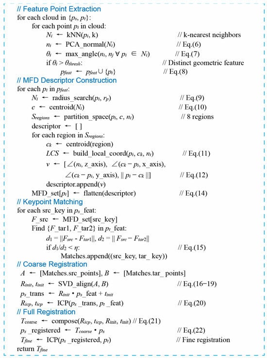
Figure 5.
Pseudo-code of developed MFD algorithm.
3. Results and Discussion
3.1. Computational Complexity and Robustness Analysis
To verify the robustness of MFD against noise and different point cloud resolutions, the Bunny point cloud ≈100,000 points was defined as the target with standard resolution. The source point clouds were generated by two ways. To test noise robustness, 1%, 2%, and 5% normal random noise were added to the standard Bunny point cloud. To test resolution difference robustness, the standard Bunny point cloud were downsampled to 1/2, 1/4, and 1/8 of its original resolution. Meanwhile, the maximum resolution difference between the point cloud to be registered and the target point cloud is 1:8.
Then, Gaussian random noise and Bunny point cloud data sampled at different resolutions are added to the same coordinate system as the point cloud to be registered, and matching experiments are performed. Gaussian random noise with a mean μ of 0 and a standard deviation σ proportional to the average point spacing davg of the Bunny point cloud is added to the point cloud to be registered. For each pair of points selected based on MFD, the Euclidean distance between the two points is calculated. If the distance is smaller than the specified threshold , the point pair is considered a correct match; otherwise, it is considered an incorrect match. Under a given threshold , recall rate is defined as the ratio of correct matching point pairs to the total number of descriptors, and registration accuracy is defined as the ratio of correct matching point pairs to the total number of matching point pairs. The F1 score and the relationship between registration accuracy and recall rate are given by
For the target point cloud and the point cloud to be registered, which are already in the same coordinate system, the point cloud matching is performed using the data processing and MFD-based registration method proposed in this paper. The final matching point pairs are analyzed. The recall rate and precision curve, along with the F1 score, are used as performance evaluation metrics.
The F1 score is used to evaluate the matching performance of the local feature descriptors, and the results are shown in Table 1. A higher F1 score indicates better performance of the local feature descriptor. All performance differences between MFD and baseline descriptors are statistically significant (p < 0.01, paired t-test). The most pronounced improvements occur under noise and downsampling conditions (p < 10−4), confirming MFD’s superior robustness, as shown in Table 2. By varying the threshold , recall and precision curves are generated, and the results are shown in Figure 6. The closer the recall and precision curve is to the vertical axis, the better the performance of the descriptor.

Table 1.
F1 scores of different local feature descriptors for point cloud data.
Table 2.
Statistical significance testing (p-values).
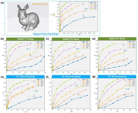
Figure 6.
Recall and precision curves of five local feature descriptors under different conditions. (a) Original point cloud data; (b) added 1% noise; (c) added 2% noise; (d) added 5% noise; (e) 1/2 downsampling; (f) 1/4 downsampling; (g) 1/8 downsampling.
From Table 1, we can see that MFD performs best under all test conditions, especially maintaining a high F1 score after noise interference and down sampling. PFH and HoPPF are sensitive to noise and resolution degradation, and their performance is significantly reduced. Although PPTFH is slightly more robust to noise, its overall accuracy is not as good as MFD. FPFH is an excellent representative of traditional methods, but it is still slightly inferior to MFD.
Figure 6 demonstrates that MFD’s curve outperforms those of other methods significantly, which indicates that MFD achieves a higher recall rate while retaining high precision. Although FPFH is also close to the vertical axis, the curve is obviously degraded under high noise conditions. Other descriptors have a large trade-off between precision and recall, which is difficult to balance. For original point cloud data, the maximum difference of F1 scores 0.38 was achieved between MFD and PFH. In the case of adding Gaussian random noise, the maximum difference of F1 scores 0.41 occurred when added 5% noise. In the case of downsampling, the maximum difference of F1 scores 0.35 occurred when added 1/2 downsampling.
Overall, the MFD-based partial-to-full point cloud registration method has the following characteristics:
- (1)
- Low computational complexity
By extracting feature points from the point cloud to be registered and the target point cloud based on feature degree, the point cloud matching process can reduce the computational load involved in constructing local feature descriptors and in the keypoint search and matching process. During the construction of local feature descriptors, using the centroid points of the keypoint’s neighborhood effectively simplifies the time and space complexity of building the descriptors. For point cloud data containing n data points, the time complexity of constructing the MFD is independent of the selected support radius and is always O(n). Moreover, the dimensionality of the descriptor is 32, which reduces the registration computational load by approximately 75% compared with FPFH 128 dimensions.
- (2)
- Strong noise robustness
Constructing descriptors based on the geometric relationship between keypoints and neighborhood partition centroids reduces the impact of isolated noise and Gaussian noise. The results show that with 5% Gaussian noise added, the F1 score of MFD reaches 0.71, significantly higher than 0.61 of FPFH and 0.30 of PFH, and the matching accuracy remains above 89% under noise interference.
- (3)
- High resolution adaptability
Centroid aggregation weakens the impact of point cloud resolution differences. In the 1/8 downsampling scenario, the F1 score of MFD is 0.63, which is better than 0.59 of FPFH and 0.38 of HoPPF, and can adapt to point cloud registration needs under different scanning accuracies.
3.2. General Dataset Registration Verification
To demonstrate the universality and effectiveness of the method proposed in this paper, partial and full point cloud registration experiments were conducted using the Stanford public datasets: Bunny and Armadillo. The computer used in the experiment is Intel Core i5-10300H CPU, NVID-IA GeForce GTX 1650 Ti GPU and 16GB RAM. The experiments were carried out using the PFH [10], FPFH [11], HoPPF [13], PPFH [28], and MFD descriptors combined with the SVD-based coordinate transformation method, as shown in Figure 7. The registration time and registration error were calculated. Registration error is defined as the ratio of the mean distance between all matching point pairs in the two point cloud sets to the point cloud resolution. A registration error threshold of 1 is set, meaning that if the ratio of the mean distance between matching point pairs and point cloud resolution exceeds 1, the registration is considered to have failed. The registration results are shown in Table 2 and Table 3.
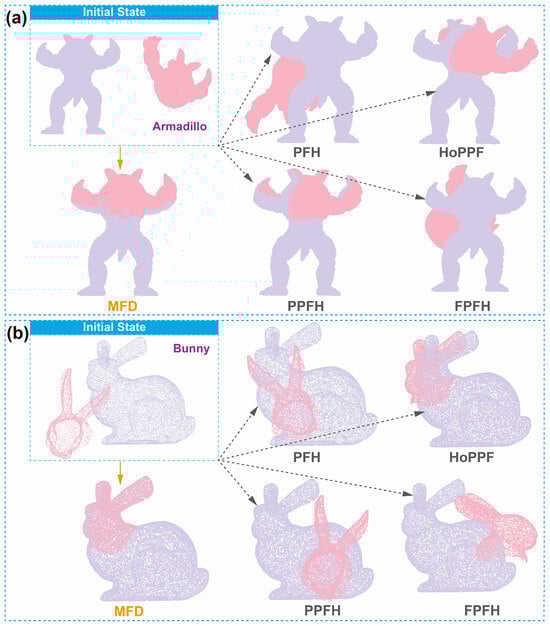
Figure 7.
Registration results. (a) Armadillo point set; (b) bunny point set.
Table 3.
Comparison of registration results between MFD and other point cloud registration methods.
In Table 3, the speed improvement rate refers to the extent to which the registration speed is increased using the MFD-based registration algorithm compared to other methods. For the Bunny and Armadillo point clouds used in the experiment, local feature descriptors based on MFD are used to register partial point clouds with the full point clouds. It can be observed that, compared to registration methods based on PFH, HoPPF, PPFH, and FPFH descriptors, MFD improves the registration accuracy by an average of 36.61% (average registration accuracy improvement rate compared with the four comparison methods) and the registration speed by an average of 55.94% (average registration speed improvement rate compared with the four comparison methods), while still achieving successful registration.
The MFD-based partial-to-full point cloud registration algorithm uses keypoints from the partial point cloud to perform point pair search and matching. By utilizing the feature point sets from both point clouds for initial registration, it enhances the distinctiveness of local feature descriptors, reduces the number of matching calculations, and improves registration efficiency. While achieving high-accuracy registration, the time required for registration using this method is significantly reduced, making it an efficient registration algorithm.
3.3. Application Experiment Verification
The complex cabin section point cloud scan procedure was shown in Figure 8. The surface area of the entire point cloud model of the workpiece is 6.9 m2, while the surface area of the point cloud of the assembly interface section that is scanned is approximately 1.17 m2. The complex cabin interface contains partially symmetric geometric structures, and the MFD method essentially captures the geometric symmetry invariance of local point clouds. The symmetric features of edges and interfaces of symmetric workpieces are still preserved during partial scanning. Figure 8a shows the CAD model of cabin assembly interface and exhaust nozzle. The entire docking equipment consists of a stationary end and a mobile end, as shown in Figure 8b. Due to the large size of the cabin, it is time-consuming to perform point cloud scanning of the entire area. Therefore, only key mating surfaces are scanned with point clouds, and then the point clouds are aligned to the overall CAD model for analysis of processing accuracy. As shown in Figure 8c, the point cloud was obtained by the Metra SCAN 3D laser scanner and C-Track optical tracker from the CREAFORM.
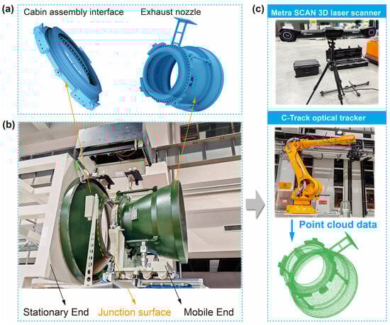
Figure 8.
Complex cabin section point cloud scan. (a) CAD model; (b) assembly interface object; (c) point cloud data acquisition method.
Registration results based on large workpiece docking assembly platform are shown in Figure 9. Figure 9a shows the initial state of workpiece point cloud. When using the traditional PFH-SVD method for registration, as shown in Figure 9b, the coarse registration process took 1062.26 s, and the ICP fine registration took 655.4 s, with a total time of 1717.66 s. Finally, the workpiece docking results was not ideal.
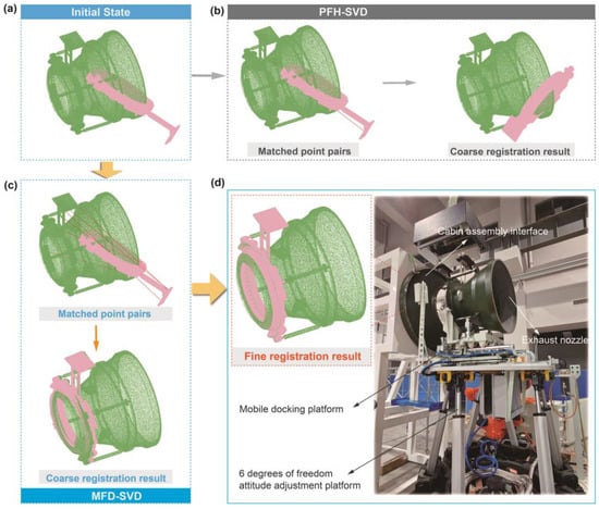
Figure 9.
Registration results based on complex workpiece docking assembly platform. (a) Initial state; (b) using the PFH-SVD method; (c) using the MFD-SVD method; (d) fine registration results.
Figure 9c shows the MFD-SVD method for workpiece docking. At first, MFD based registration method for coarse registration of the workpiece’s partial point cloud and the design model’s overall point cloud. Then, the fine registration using the ICP algorithm was adopted. The coarse registration process took 335.96 s, and the ICP fine registration took 589.12 s, with a total time of 925.08 s. The registration time achieved 46% reduction. The fine registration results are shown in Figure 9d. The complex workpiece docking assembly platform was composed of 6 degrees of freedom attitude adjustment platform and mobile docking platform.
SVD incorrect matches occurred, leading to a registration failure. However, using the MFD-SVD method successfully achieved the registration of the partial point cloud and the overall point cloud of the complex workpiece. Based on this, assembly dimension inspection work was carried out. And on this basis, the docking assembly was completed. Figure 9 shows the docking assembly platform used.
The experimental results in Section 3.1 and Section 3.2 show that for the registration of partial point clouds and complete point clouds of complex workpieces, where there are feature differences between the point clouds to be registered and the target point clouds, traditional methods based on local feature descriptors (such as PFH, HoPPF, PPFH, FPFH) combined with RANSAC for point cloud registration are inefficient. In contrast, the MFD-based feature descriptor method proposed in this paper effectively expresses the local features of the extracted point set. The strategy of using key points from the partial point cloud for pair matching ensures the accuracy of the matched point pairs, achieving successful registration of the partial point cloud and the complete point cloud for workpieces. While MFD demonstrates efficiency for industrial-scale workpieces (≤2.1M points), its extension to giga-point clouds (e.g., full-aircraft scans >100M points) warrants analysis.
In addition, in practical industrial scenarios, registration often involves two sets of point clouds. The overlap rate of partially overlapping point clouds usually ranges from 30% to 50%, while gaps mostly result from scanning omissions or minor surface defects of workpieces, with a gap ratio ≤10%. When the two point clouds have partial overlap and gaps, the method proposed in this paper also has corresponding advantages. In scenarios with small gaps, even if some points are missing, the features of adjacent valid points can still support the discriminability of descriptors and reduce the impact of gaps on matching accuracy. For moderate overlap rates, the early feature point screening step of the method has retained key geometric feature points, which have a high repetition rate in the overlapping region and can provide sufficient corresponding relationships for registration.
4. Conclusions
In this study, a novel registration method for partial overlapping point cloud data based on the MFD was proposed to address the challenges of aligning complex workpieces. By extracting and leveraging geometric symmetry-invariant features from local point clouds, the method solves practical partial-to-whole registration problems. The method constructs robust local feature descriptors by encoding the spatial relationships between key points and centroids within segmented neighborhoods. Through coarse registration based on descriptor matching and refined alignment using the ICP algorithm, the approach achieves accurate and efficient transformation between partial scans and complete point cloud models.
- (1)
- Extensive experiments demonstrate that the MFD-based method outperforms traditional descriptors such as PFH, FPFH, HoPPF, and PPTFH in terms of matching precision, computational efficiency, and robustness under varying noise levels and resolution degradations.
- (2)
- Compared to existing feature descriptors, MFD consistently maintains high F1 scores and produces precision–recall curves closer to the ideal, confirming its superior resilience and adaptability.
- (3)
- The reduced dimensionality of the descriptor (32D) enhances the overall computational performance, making it suitable for real-time applications in precision measurement, virtual assembly, and intelligent manufacturing systems.
The proposed method offers a reliable and scalable solution for partial-to-whole point cloud registration tasks and demonstrates broad applicability across diverse scenarios involving complex and incomplete geometric data. Future work will focus on further improving descriptor learning efficiency and integrating deep learning-based registration techniques to enhance performance in highly unstructured environments.
Author Contributions
Methodology, software, validation, writing—original draft, H.W.; supervision, funding acquisition, L.L.; data curation, formal analysis, H.S.; investigation, visualization, M.X.; resources, project administration, Z.X. All authors have read and agreed to the published version of the manuscript.
Funding
This study was supported by the LiaoNing Revitalization Talents Program (No. YS2023004).
Data Availability Statement
The data presented in this study are available on request from the corresponding author.
Conflicts of Interest
The authors Haicheng Shi and Minyan Xin were employed by the Liaoshen Industries Group Co., Ltd. The remaining authors declare that the research was conducted in the absence of any commercial or financial relationships that could be construed as a potential conflict of interest. This study was supported by the LiaoNing Revitalization Talents Program (No. YS2023004). The funding agency had no involvement in the study design, data collection, analysis, interpretation of data, the writing of the manuscript, or the submission of the manuscript.
References
- Qiu, Q.; Wang, M.; Guo, J.; Liu, Z.; Wang, Q. An adaptive down-sampling method of laser scan data for scan-to-BIM. Autom. Constr. 2022, 135, 104135. [Google Scholar] [CrossRef]
- Wu, C.; Yuan, Y.; Tang, Y.; Tian, B. Application of terrestrial laser scanning (TLS) in the architecture, engineering and construction (AEC) industry. Sensors 2021, 22, 265. [Google Scholar] [CrossRef]
- Reyno, T.; Marsden, C.; Wowk, D. Surface damage evaluation of honeycomb sandwich aircraft panels using 3D scanning technology. NDT E Int. 2018, 97, 11–19. [Google Scholar] [CrossRef]
- Li, D.; Li, X.; Li, C. Embrace descriptors that use point pairs feature. Vis. Comput. 2024, 40, 9005–9016. [Google Scholar] [CrossRef]
- Yue, X.; Liu, Z.; Zhu, J.; Gao, X.; Yang, B.; Tian, Y. Coarse-fine point cloud registration based on local point-pair features and the iterative closest point algorithm. Appl. Intell. 2022, 52, 12569–12583. [Google Scholar] [CrossRef]
- Jiang, X.; Ma, J.; Xiao, G.; Shao, Z.; Guo, X. A review of multimodal image matching: Methods and applications. Inf. Fusion 2021, 73, 22–71. [Google Scholar] [CrossRef]
- Barberi, E.; Cucinotta, F.; Forssén, P.E.; Raffaele, M.; Salmeri, F. A differential entropy-based method for reverse engineering quality assessment. In Proceedings of the International Conference of the Italian Association of Design Methods and Tools for Industrial Engineering, Florence, Italy, 6–8 September 2023; Springer Nature: Cham, Switzerland, 2023; pp. 451–458. [Google Scholar]
- Adolfsson, D.; Castellano-Quero, M.; Magnusson, M.; Lilienthal, A.J.; Andreasson, H. CorAl: Introspection for robust radar and lidar perception in diverse environments using differential entropy. Robot. Auton. Syst. 2022, 155, 104136. [Google Scholar] [CrossRef]
- Salmeri, F.; Barberi, E.; Lipari, F.; Nicita, F. A novel quality assessment method for the clinical reproduction of orthodontic attachments based on differential entropy. Eng. Proc. 2023, 56, 15. [Google Scholar]
- Ma, J.; Jiang, X.; Fan, A.; Jiang, J.; Yan, J. Image matching from handcrafted to deep features: A survey. Int. J. Comput. Vis. 2021, 129, 23–79. [Google Scholar] [CrossRef]
- Ebadi, K.; Bernreiter, L.; Biggie, H.; Catt, G.; Chang, Y.; Chatterjee, A.; Denniston, C.E.; Deschênes, S.-P.; Harlow, K.; Khattak, S.; et al. Present and future of slam in extreme environments: The darpa subt challenge. IEEE Trans. Robot. 2023, 40, 936–959. [Google Scholar] [CrossRef]
- Du, G.; Wang, K.; Lian, S.; Zhao, K. Vision-based robotic grasping from object localization, object pose estimation to grasp estimation for parallel grippers: A review. Artif. Intell. Rev. 2021, 54, 1677–1734. [Google Scholar] [CrossRef]
- Zhao, H.; Tang, M.; Ding, H. HoPPF: A novel local surface descriptor for 3D object recognition. Pattern Recognit. 2020, 103, 107272. [Google Scholar] [CrossRef]
- Wu, L.; Zhong, K.; Li, Z.; Zhou, M.; Hu, H.; Wang, C.; Shi, Y. PPTFH: Robust local descriptor based on point-pair transformation features for 3D surface matching. Sensors 2021, 21, 3229. [Google Scholar] [CrossRef]
- Berker Logoglu, K.; Kalkan, S.; Temizel, A. CoSPAIR: Colored histograms of spatial concentric surflet-pairs for 3D object recognition. Robot. Auton. Syst. 2016, 75, 558–570. [Google Scholar] [CrossRef]
- Zaganidis, A.; Sun, L.; Duckett, T.; Cielniak, G. Integrating deep semantic segmentation into 3-D point cloud registration. IEEE Robot. Autom. Lett. 2018, 3, 2942–2949. [Google Scholar] [CrossRef]
- Shah, G.A.; Polette, A.; Pernot, J.P.; Giannini, F.; Monti, M. Simulated annealing-based fitting of CAD models to point clouds of mechanical parts’ assemblies. Eng. Comput. 2021, 37, 2891–2909. [Google Scholar] [CrossRef]
- Li, J.; Chen, B.; Yuan, M.; Zhao, Q.; Luo, L.; Gao, X. Matching algorithm for 3D point cloud recognition and registration based on multi-statistics histogram descriptors. Sensors 2022, 22, 417. [Google Scholar] [CrossRef]
- Wang, Y.; Solomon, J. Deep closest point: Learning representations for point cloud registration. In Proceedings of the 2019 IEEE/CVF International Conference on Computer Vision (ICCV), Seoul, Republic of Korea, 27 October–2 November 2019; pp. 3522–3531. [Google Scholar]
- Lu, W.; Wan, G.; Zhou, Y.; Fu, X.; Yuan, P.; Song, S. DeepVCP: An end-to-end deep neural network for point cloud registration. In Proceedings of the 2019 IEEE/CVF International Conference on Computer Vision (ICCV), Seoul, Republic of Korea, 27 October–2 November 2019; pp. 12–21. [Google Scholar]
- Wang, Y.; Solomon, J.M. PRNet: Self-Supervised Learning for Partial-to-Partial Registration. In Proceedings of the Advances in Neural Information Processing Systems, Vancouver, BC, Canada, 8–14 December 2019. [Google Scholar]
- Choy, C.; Dong, W.; Koltun, V. Deep global registration. In Proceedings of the 2020 IEEE/CVF Conference on Computer Vision and Pattern Recognition (CVPR), Seattle, WA, USA, 13–19 June 2020; pp. 2511–2520. [Google Scholar]
- Sarode, V.; Dhagat, A.; Srivatsan, R.A.; Zevallos, N.; Lucey, S.; Choset, H. MaskNet: A fully-convolutional network to estimate inlier points. In Proceedings of the 2020 International Conference on 3D Vision (3DV), Fukuoka, Japan, 25–28 November 2020; pp. 1029–1038. [Google Scholar]
- Kazerouni, I.A.; Fitzgerald, L.; Dooly, G.; Toal, D. A survey of state-of-the-art on visual SLAM. Expert Syst. Appl. 2022, 205, 117734. [Google Scholar] [CrossRef]
- Sang, M.; Wang, W.; Pan, Y. RGB-ICP method to calculate ground three-dimensional deformation based on point cloud from airborne LiDAR. Remote Sens. 2022, 14, 4851. [Google Scholar] [CrossRef]
- Stilla, U.; Xu, Y. Change detection of urban objects using 3D point clouds: A review. ISPRS J. Photogramm. Remote Sens. 2023, 197, 228–255. [Google Scholar] [CrossRef]
- Yang, J.; Li, H.; Campbell, D.; Jia, Y. Go-ICP: A globally optimal solution to 3D ICP point-set registration. IEEE Trans. Pattern Anal. Mach. Intell. 2016, 38, 2241–2254. [Google Scholar] [CrossRef] [PubMed]
- Buch, A.G. Local point pair feature histogram for accurate 3D matching. In Proceedings of the 29th British Machine Vision Conference, BMVC 2018, Newcastle upon Tyne, UK, 3–6 September 2018; Volume 143. [Google Scholar]
Disclaimer/Publisher’s Note: The statements, opinions and data contained in all publications are solely those of the individual author(s) and contributor(s) and not of MDPI and/or the editor(s). MDPI and/or the editor(s) disclaim responsibility for any injury to people or property resulting from any ideas, methods, instructions or products referred to in the content. |
© 2025 by the authors. Licensee MDPI, Basel, Switzerland. This article is an open access article distributed under the terms and conditions of the Creative Commons Attribution (CC BY) license (https://creativecommons.org/licenses/by/4.0/).