1. Introduction
Carbonate reservoirs are a globally distributed unconventional oil and gas resource with low matrix permeability and poor connectivity among natural discontinuities [
1]. These qualities cause oil and gas to be spread, making it difficult to explore [
2,
3]. It is frequently essential to artificially communicate independent natural cracks and caverns in order to improve the poor natural recuperation. Hydraulic fracturing has frequently been used as an efficient stimulation recovery strategy [
4,
5].
Understanding the concurrent impact of natural discontinuities and complicated stress conditions on hydraulic fracture propagation is a problem in the use of this technology. Numerous studies on this topic were conducted over the last three decades. For instance, Zhang and co-authors [
6] first conducted true triaxial hydraulic fracturing experiments in China by presetting a weak layer in artificially cast concrete, which proved that the natural weakly cemented stratigraphic surface affects the direction of the hydraulic fractures. Recently, some conducted experimental and simulation studies [
4,
5,
6,
7] were conducted on the mechanisms of hydraulic fracturing. There is a consensus that parameters such as fracturing fluid displacement, stress variance coefficient, natural fracture geometry, and density all affect the expansion of hydraulic fractures and cause them to change. Fu et al. [
5] established an explicit coupling theory model for fluid–structural mechanics to simulate hydraulic fracturing in fractured reservoirs. Sneddon [
8] investigated the stress distribution near a single fracture, and proved that the expansion of a hydraulic fracture would reconfigure the stratigraphic stress field through mathematical modeling and derivations, first proposing the effect of “stress shadowing”. Cheng [
9] further discussed the change in the stress field and the geometry of the fracture based on the boundary element method, and concluded that the fracture geometry and density would be influenced by the fracturing fluid displacement. Overall, the relationship between the crack extension and the stress field has been confirmed to be an interactive coupling relationship. However, the influence of macroscopic natural discontinuities (macro-cracks, holes, etc.) on the emergence and expansion of cracks, particularly under the consideration of the poromechanical effect, are rarely reported.
For more than 80 years, researchers have studied the poromechanical effects in a porous medium, since Biot [
10] derived the effective stress using Terzaghi’s principle [
11]. The fundamentals of rock-like poroelasticity were initially studied by Coussy [
12] and other scientists, and the poroelastic theory has been used in numerous studies regarding engineering applications. Determining the poroelastic characteristics of rock materials under overpore pressure remains a hot topic to this day. Researchers like [
13,
14] directly assessed the poroelastic behavior of sandstone using a range of experimental techniques, and their findings show that pore pressure has a major impact on the macroscopic strength of sandstone.
It should be underlined that laboratory measurements are primarily focused on drained conditions due to the difficulties of realizing undrained conditions. On the other hand, laboratory experimental measurements of the local poroelastic properties of large-size materials are relatively scarce. In contrast, undrained responses are frequently observed in field measurements, especially in oil and gas applications. A number of papers, such as those by Cheng et al. (1993, 2008), Ghabezloo et al. (2008), Chen et al. (2009), Belmokhtar et al. (2017), and Wong (2017) [
15,
16,
17,
18,
19,
20,
21], have studied the isotropic poroelastic behavior of different porous media materials (such as concrete, granite, and sandstone) under undrained conditions through numerical simulations, predicting various parameters, such as the drained modulus, storage modulus, and effective stress coefficients.
When examining the poroelastic characteristics of rocks under overpressure settings, the majority of the experimental research concentrated on the initial (undamaged) state or under hydrostatic stress conditions. When hydraulic fracturing is used, massive fluid injections into the formation may cause fissures to form and spread throughout the overpressured zone. This can result in nonlinear stress–strain relationships, the degradation of elastic properties, the induction of anisotropy, volumetric dilation, material softening, and permeability variations. However, it is challenging to carry out laboratory experiments to investigate the evolution of the poromechanical behavior of damaged overpressured materials. Thus, proper numerical studies are needed to provide insights into this unsolved problem. This work focuses on simulating 2D hydraulic fracturing in overpressure carbonate formations, such as macro-cracks and caves, utilizing the discrete element method. Specifically, the impact of poromechanical processes on microcrack opening was taken into account. Providing some theoretical references for oilfield fracturing operations is the goal of this paper.
2. Theoretical Background
In carbonate reservoirs, hydrocarbon-rich natural discontinuities often exhibit localized overpressure characteristics. This can be attributed to the co-effects of organic matter maturation and intense tectonic movements. Following Biot’s theory, the stress,
σ, is a function of pore pressure (
PP):
where
and
represent effective stress and total stress in MPa, respectively.
b is the pore water pressure coefficient;
is the Kronecker symbol. Equation (1) is often used to study the apparent stress of rock media when pore pressure exists.
Then, the stress–strain correlation of a porous medium with a certain pore pressure can be expressed as:
where
λ and
G are the Lamé’s constants and shear modulus, respectively.
is the overall volumetric strain;
is the rock strain tensor. For a saturated case, the pore volume change (Δ
n) due to pore pressure variations (
) can be expressed as:
where
Q and
H are the Biot constants. 1/
Q characterizes the change in water volume due to pore fluid pressure variations, and 1/
H represents the change in the total volume of the solid medium, respectively. Equation (3) implies that pore pressure changes could affect the micro-structures of the rock matrix, and hence the strength of the reservoir rock. From an engineering operation perspective, changes in the strength of the rock matrix will inevitably affect the recovery enhancement effect of the hydraulic fracturing. Thus, the pore pressure effect should be considered in the hydraulic fracturing design.
Field-scale permeability experiments demonstrated a strong coupling relationship between pore pressure
and the minimum principal stress
. Based on the in situ experimental results obtained from the Scotian Shelf reservoir in Canada, Engelder and Fischer [
22] formulated a simplified relationship that describes the correlation between
and
. This relationship is expressed as:
where
is the minimum principal stress in MPa;
is the maximum principal stress in MPa;
ν is the Poisson’s ratio. Equation (5) illustrates that, under the overpressure conditions, pore pressure can be linked to the external stress states. Therefore, if
and
are known, one can directly derive the local pore pressure. This leads to the use of the discrete element method (DEM) to simulate hydraulic micro-fractures. The following section introduces the calculation principles.
3. Numerical Simulation Principles
Potyondy and Cundall [
23] pioneered the bonded particle model (BPM), which simulates the mechanical behavior of rock-like materials using proper circular particle-to-particle bonding. The parallel bonding model, which is characterized by micro-scale bonding stiffness and micro-scale contact stiffness, is used in this study to determine the macro-scale stiffness. When the bonding fails, the macro-scale stiffness diminishes, offering a more faithful representation of the mechanical properties of a confined medium such as carbonate rock.
Figure 1 illustrates the parallel bond model. In this model,
and
represent the normal and tangential contact stiffness, respectively;
and
represent the average normal and tangential stiffness of parallel bonding, respectively;
is the spacing between upper and lower parallel bonds;
,
and
are the normal contact force, tangential contact force, and the inclination angle of the rupture envelope; and
v is the coefficient of friction.
It should be noted that the vacant space in a BPM is made up of pores and fractures. Assuming that pores store water and fracture channels carry water, and that two water heads, the pore medium water head and the fracture medium water head, are created in the dual-medium system, the pores and fractures are therefore coupled by fluid exchange. Fluid transport is believed to obey Darcy’s law and the cubic law due to the large variation in porosity and permeability between fractures and pores:
where
k is the conductivity coefficient,
a is the mean diameter of the fluid exchange channel in meters,
is the pressure difference between adjacent domains in Pascals, and
L is the sum of the radii of adjacent contacting particles in meters.
a can be considered a function of the normal force applied to the fracture walls. When the normal force is zero,
a is the residual aperture. As the normal pressure increases,
a decreases and can be defined as:
where
is the residual aperture of the channel in meters, and
is the normal pressure when the aperture
decreases to 0.5
in Pascals. Within one time-step, Δ
t, the change in fluid pressure within the void is given by:
where
is the volumetric modulus of the fluid,
is the total volumetric flow volume obtained from the surrounding channels, and Δ
is the change in the spatial volume of the pore domain.
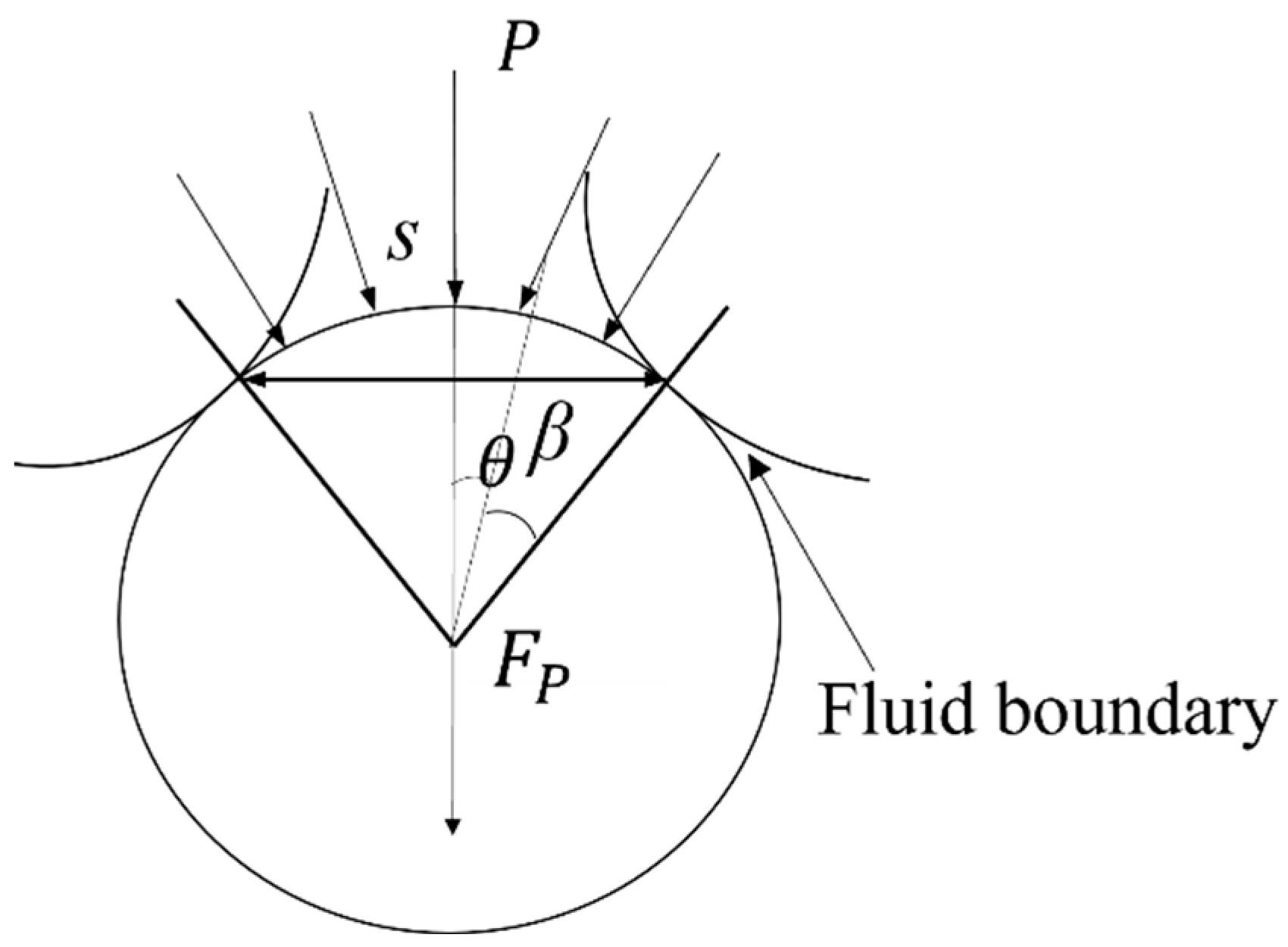
According to
Figure 2, the fluid pressure within the void is evenly spread on the surface of the solid particles. In our model, there are two contact locations between the three nearby particles. Because the particles are spherical and have a constant surface curvature, the two contact sites and the particle surface connecting them can be thought of as a symmetric structure. As a result, as the pore pressure rises, and the contact forces at the two locations become symmetrically equal. As a result, a force acts on the particles:
where
β is the half angle of the fluid void boundary;
l is the spacing between adjacent particles.
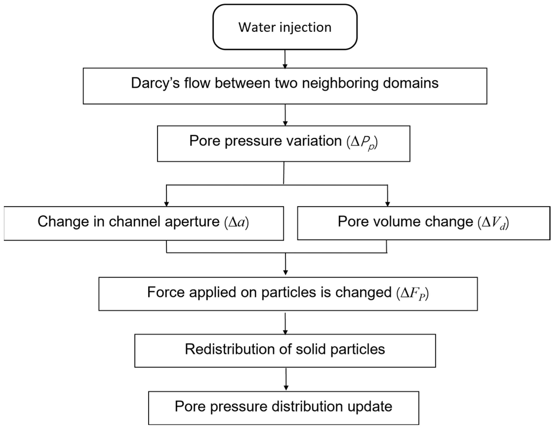
In summary,
Figure 3 illustrates the idea of pore pressure variation calculations that consider fluid–stress coupling. The coupling between the bound particle model and fluid is realized according to three assumptions:
The change in intergranular contact force affects the channel aperture, increasing fluid exchange between different domains;
The forces acting on the particles change the spatial structure of the pore volume, thereby further altering the pressure within;
The pore pressure has an effect on the particles around it.
4. Numerical Modeling and Parameterization
In order to ensure that the numerical model can represent the real carbonate rock, and to account for the precision of calculations, it is necessary to calibrate the micro-scale mechanical parameters and other computational parameters before the simulation. Due to size effects, it is not possible to directly determine micro-scale mechanical parameters from macroscopic parameters. Therefore, an inverse calibration method is employed to determine reasonable micro-scale parameters based on reference [
23]. To do this, first, a sensitivity analysis is conducted to assess the impact of each micro-scale parameter on the simulation results. Then, the macroscopic observational data are compared with the simulation results and, based on a gradient descent algorithm, the micro-mechanical parameters are adjusted to minimize errors in macroscopic behavior. Finally, through an iterative process, micro-scale parameters are continuously defined and discrete element simulations are rerun until the deviation between the simulated and experimental results falls within a reasonable range, i.e., 5%.
We used the experimental results from the literature [
24,
25,
26] as macroscopic parameters for calibration. Some important physical properties are shown in
Table 1. A uniaxial compression simulation, without considering pore fluid pressure, was conducted to record the stress–strain curve of the rock sample. After conducting inverse calculations, the micro-scale mechanical parameters of the shale were determined and are shown in
Table 2.
Figure 4 provides an illustration of this comparison. The laboratory and numerical results show a high degree of consistency; in particular, the peak deviator stress in the experimental result agrees well with the numerical simulation. Thus, it can be said that the numerical rock model’s micro-scale mechanical characteristics satisfy the necessary conditions, enabling the execution of relevant numerical tests.
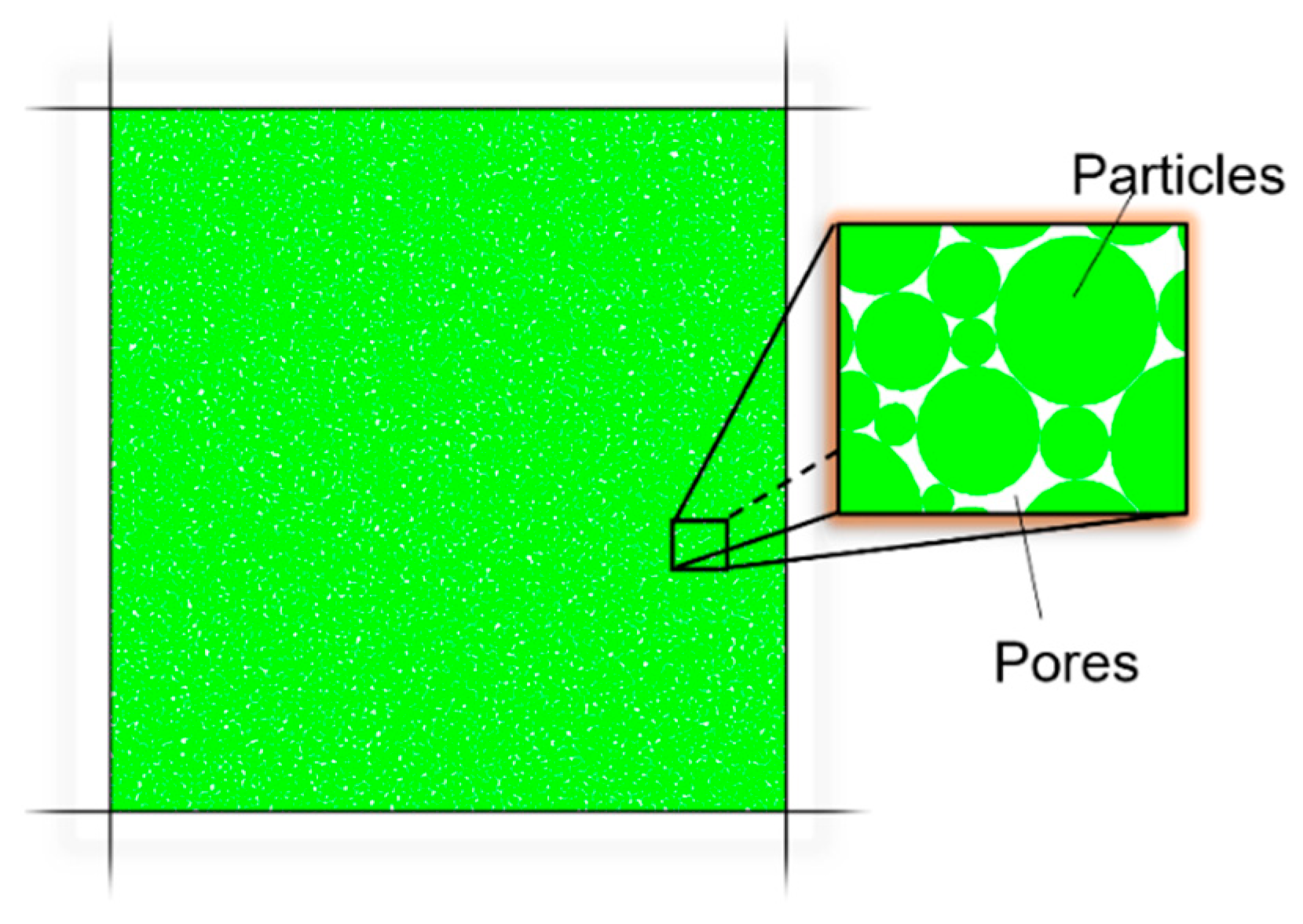
The numerical carbonate sample has the following characteristics: it has dimensions of 2 m × 2 m, a porosity of 0.04, and consists of 16,786 particles; see
Figure 5. The ratio of the maximum to minimum particle diameter is 1.66, with an average particle radius of 7 mm. Particle radii follow a uniform distribution. The binding between particles is of the parallel bond type, and the bond strength follows a normal distribution. The sample is enclosed by four walls, with two vertical walls used to apply
, and the two longitudinal ones used to load
.
5. Validation of Poromechanical Effect under Overpressure Conditions
The poromechanical effect under overpressure conditions was initially studied through a series of direct shear experiments and is illustrated in
Figure 6. Four different pore pressure values were considered; see
Table 3. These pore pressure values were determined by controlling the four walls shown in
Figure 5, according to Equation (4). Fluid parameters were assigned based on the sensitivity analyses of hydraulic fracturing simulation provided in the literature, such as reference [
25]; see
Table 4.
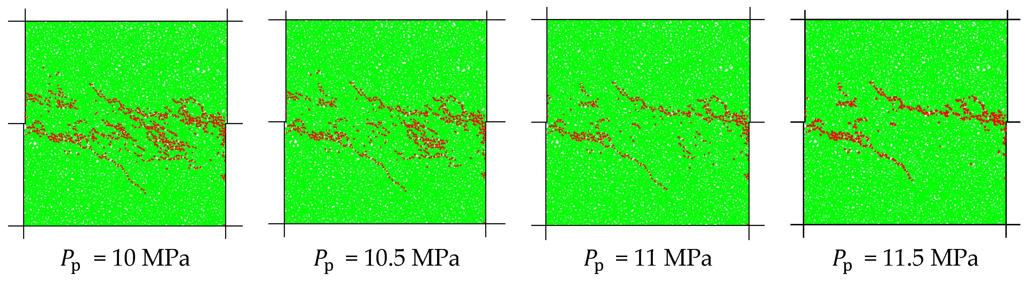
The simulation results provided insights into the stress–strain relationship of the material with different pore pressures. Intuitively, as the pore pressure rises, the number and density of cracks significantly decrease. This clearly shows that the pore pressure increased the shear strength of the material.
Figure 7 illustrates the stress–strain curves for rock specimens at various pore pressures under a fixed minimum horizontal principal stress. One can note that, during the elastic deformation phase, rock samples are approximately similar. The slope of the curves corresponds to the elastic modulus, and can be considered roughly equivalent. With increasing pore pressure, the material’s peak strength increases, and the peak strain gradually shifts to the right.
Table 4 summarizes the simulated results of four pore pressure scenarios. These results demonstrate that the local increase in pore pressure mitigates a portion of the overall stress. Based on a DEM method, this is microscopically manifested as decreases in
and
, as depicted in
Figure 1. This decrease increases the ultimate failure strength and lessens the external force placed on the interparticle cementation. From an engineering standpoint, our simulation results verify that excessive pressure reduces effective stress, which improves the rock’s capacity for shear resistance and flexibility.
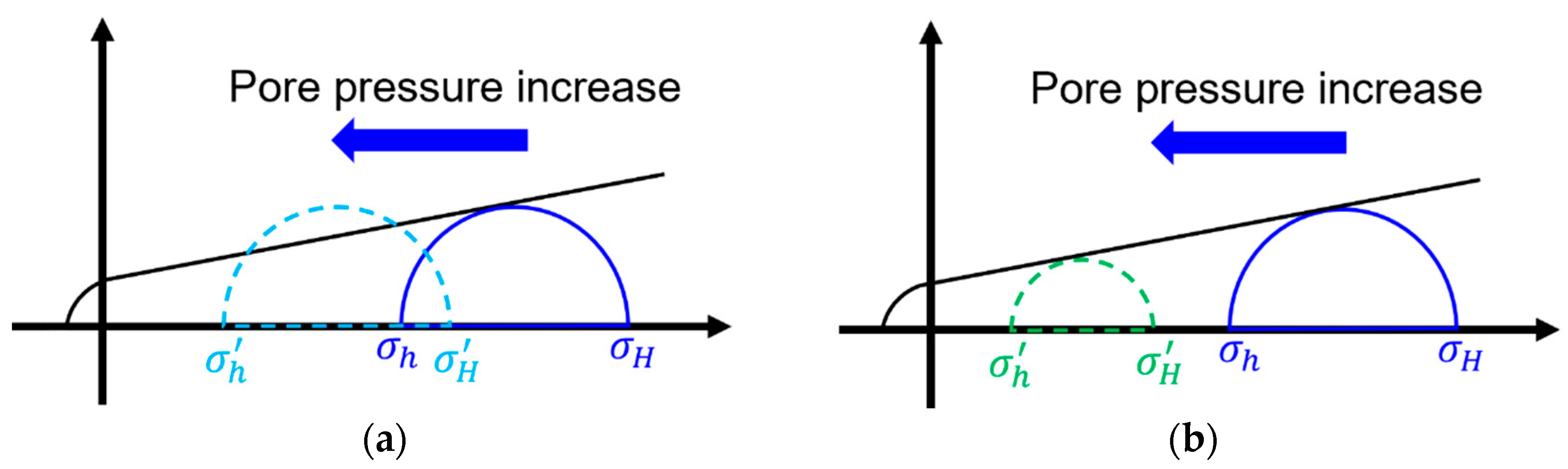
We can examine the relationship between external stress and pore overpressure using the Griffith–Coulomb failure criterion. The stress path effects under the traditional Mohr–Coulomb criterion are shown in
Figure 8a, where the diameter of the Mohr circle indicates the horizontal differential stress values. Pore pressure is also a factor in this analysis. A modified Mohr–Coulomb fracture criterion that takes into account the coupling impact of the pore fluid overpressure and the stress field is shown in
Figure 8b. It assumes that the maximum principal stress remains the same as the horizontal maximum principal stress when there is an increase in pore fluid overpressure. The coefficient term in Equation (4) increases, while the horizontal stress differential coefficient decreases, reflecting the stress changes in the stress path diagram, as depicted in
Figure 8b. The Mohr circle gradually decreases in diameter as it moves towards the origin of the Cartesian coordinate system, making it more challenging to intersect the Mohr–Coulomb rupture envelope.
In summary, a coupling relationship exists between the external stress and pore overpressure. An increase in pore pressure leads to variations in horizontal differential stress and plays a promoting role in the stability of the rock mass.
6. Hydraulic Fracturing Simulation
Drawing from the aforementioned study, we performed hydraulic fracturing while taking pore overpressure into account, particularly when dealing with hydraulic fracturing fluids that possess high energy, high pressure, and a large volume. The main goal of our simulation was to investigate how injection pressure and stress distribution affect the spread of fractures. The experimental schedule was as follows.
The rock model was subjected to confinement by four rigid walls; see
Figure 5. The two vertical walls were used to load
and the two longitudinal walls were used to load
. A constant horizontal stress differential coefficient ((
−
)/
) of 20% was maintained during loading confinement to 40 MPa. Once the “walls-particles” system was stabilized,
was kept constant and
changed to different values to create an overpressure condition.
remained at 40 MPa and
decreased to 35 MPa. Assuming Biot’s coefficient is 1, according to Equation (4), the corresponding pore overpressure is 31.26 MPa. Fracturing fluid was injected into the model at a constant 70 MPa through a circular pressure source with a radius of 1.5 cm, located at the center of the model (
Figure 9b). During injection, the interior of the model exhibited a constant pressure gradient from the injection origin to the model boundaries.
To simulate the discontinuous nature, a carbonate reservoir model was used, derived from three in situ logging tests of the Tahe oilfield in western China; see
Figure 9a. In the figure, the radii of the three concentric circles, from inner to outer, are 50 m, 100 m, and 300 m. This carbonate reservoir is characterized by highly developed cavities and fractures. Unlike conventional oil and gas reservoirs, it exhibits pronounced heterogeneity. The color represents the useful reserve abundance. The volume of oil increases from blue to red. One can note that the primary storage spaces are cavities formed due to structural deformations. Based on this model, a DEM sample was created, as shown in
Figure 9b.
In general, hydraulic fracturing operations only create fractures that propagate along the maximum horizontal principal stress direction, and it is challenging to fully communicate the discretely distributed cavities, and especially difficult to mobilize the remaining oil over long distances. Zhang et al. (2004) [
6] demonstrated, through numerical simulations, that fluid viscosity affects fracture propagation morphology. Following this line of thought, this study employed the DEM sample to investigate the impact of different fluid viscosities on fracture morphology and extension, considering the poromechanical effect.
Based on the parameters of the fracturing operations conducted in the Tahe oilfield, the fracturing fluid viscosity was found to be around 10 mPa·s and the injection rate ranged from approximately 0.5 to 2 m
3/s. The wellbore size was scaled down based on our model and the injection rate was set to 2 × 10
−5 m
3/s. The results of fracturing at a conventional viscosity are illustrated in
Figure 10a. It is evident that fractures formed during conventional fracturing operations still follow the fundamental of extension along the maximum principle stress direction. At 1000 steps, the large nearby caverns induce the fracture direction to turn toward them, leading to artificial fractures being redirected toward the caverns. As fracturing continues to 4000 steps (
Figure 10b), although the number of fractures increases, all fractures develop between the two caverns near the pressure source, creating a densely fractured area. The cave in the distance remains unconnected to the fractures.
Figure 10c,d present the fracture propagation with an injection fluid of 40 mPa·s. On the other hand, it is evident that a greater fluid viscosity leads to a greater number and increase in the branching morphology of hydraulic fractures. By making the fracturing fluid more viscous, it is possible to create artificial hydraulic fractures with several branches, expand the “fractured zone”, and link the distant cave. This is explained by the high-viscosity fluid, which promotes fracture propagation and the formation of a complex fracture network structure by causing the hydraulic fractures to have a lower reliance on the maximum principle stress.
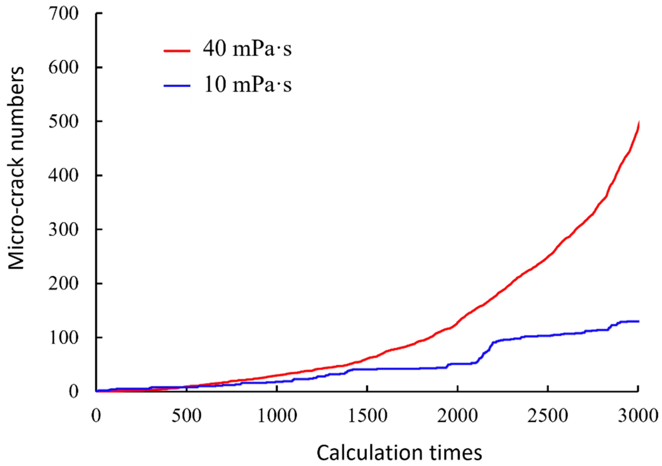
The amount of microcracks that occurred during the simulation was also noted, see
Figure 11. It is evident that whilst the value of the test with a higher fluid viscosity exponentially and quickly increased, the micro-crack numbers for the test with a lower fluid viscosity rose slowly. This suggests that using high-viscosity fracturing fluids can improve fracturing efficiency by creating a large increase in fracture area.
7. Conclusions
In order to better understand hydraulic fracturing in carbonate rock formations, this study uses discrete element numerical models, highlighting the distinctive qualities of carbonate rock, such as its tight structure and the localized overpressure in its pores. This study examined the influence of poromechanical processes on the mechanical behavior of overpressured carbonate rock, drawing on the poroelasticity theory. The study particularly examines the relationship between external confining stress and pore pressure in overpressured carbonate, and the results show that pore pressure significantly increases shear strength. Furthermore, simulations of hydraulic fracturing were carried out in carbonate reservoirs under excessive pressure, taking natural discontinuities into account. The impact of injected fluid viscosity on the fracturing process is briefly discussed, and a higher viscosity is found to promote artificial fracture branching and increase the fracturing area. The main observations are as follows:
The existence of coupling between pore pressure and external confining stress in overpressured carbonate rock was observed, resulting in a substantial increase in shear strength;
Increased viscosity of the fracturing fluid is found to enhance artificial fracture branching, leading to a notable expansion of the fracturing area in overpressured carbonate reservoirs;
The theoretical insights gained from this work have significant implications for optimizing hydraulic fracturing operations in overpressured carbonate rock fields; notably, increasing the viscosity of the injected fluid results in more microfractures and a more complex fracture network.
In the future, we aim to enhance the comprehensiveness of hydraulic fracturing simulations by expanding them to three dimensions and incorporating the poromechanical effect. This endeavor seeks to advance our understanding of spatial fracture extension patterns.


