Abstract
Active support using highly prestressed cable bolts and anchor cables has become a mainstream support technology for coal mine roadways. However, the ability of bolts and anchor cables to withstand transverse shear decreases with the prestress level, jeopardizing mining safety. This study proposed a technical solution to this problem featuring anchor cables enclosed in an axisymmetrical tube with a C-shaped cross-section (ACC), which are highly prestressed and can withstand high transverse shear. The ACC mechanical performance was tested in the #318 gas extraction roadway of the Shuangliu Coal Mine, China, characterized by extensive deformation under original support conditions. Theoretical analysis, laboratory tests, numerical simulation, and field tests were performed to analyze the shear mechanical properties of the ACC and anchor cables alone. The double shear test results revealed that the proposed ACC scheme increased the transverse shear resistance and stiffness by 10–25% and 20–40%, respectively. The FLAC3D numerical simulation showed that the roof-and-floor and rib-to-rib convergences decreased by 9.53 and 25.11%, respectively. The area of the stress concentration zone also decreased. Field monitoring showed that the ACC achieved good support performance. During the monitoring period, the maximum roof-and-floor and rib-to-rib displacements were 40 and 49 mm, respectively. The ACC scheme offered adequate shear resistance and effectively controlled surrounding rock deformation in the gas extraction roadway under study, making it applicable to similar engineering scenarios.
1. Introduction
The annual growth of China’s total energy and coal consumption in 2022 amounted to 4.3 and 2.9%, respectively, reaching 5.41 billion tons of coal equivalent. Thus, coal remains China’s energy supply in the foreseeable future and is mainly excavated by underground mining via roadways [1,2,3]. Roadway support has to meet rising demands as the mining stresses and depth increase continuously [4,5,6]. Therefore, it is highly important to investigate and innovate roadway support technology.
Highly prestressed, high-strength, high-stiffness bolts and anchor cables are dominant ingredients of roadway support in China and have proven effective for complex, difficult roadways [7,8,9,10,11,12,13]. Recently, in-depth research has been conducted on support members, such as bolts and anchor cables. Below are some representative studies in this field. Kang et al. proposed a theory of highly prestressed bolt support [14], which implied that dramatically increasing the initial support stiffness and strength of the bolt anchorage system was effective for controlling the expansion deformation and maintaining the integrity of the surrounding rocks. He et al. described a constant-resistance-large-deformation bolt, which accommodated the large deformation of surrounding rocks under constant resistance while absorbing the energy of the rock masses undergoing impact deformation [15]. Wu et al. presented compression-type (or CTC-yield) bolts [16], in which the inner thread segment composed the inner anchorage section of the bolt that was firmly fixed at the borehole bottom, while the bolt’s smooth section would elongate in response to rock deformation when the load exceeded its capacity. This effectively optimized the stress distribution at the bolt-grout-rock interface. Tahmasebinia et al. conducted extensive analysis of the key parameters of anchor rods under dynamic and static conditions through numerical simulation methods, providing a reference for other scholars when choosing support schemes [17,18]. Pyon et al. studied a rock energy-absorbing bolt (the so-called D-bolt), comprising a smooth steel bar with a number of anchors along its length [19]. Sakhno and Sakhno proposed considering the impact of rock mass fracture over time on rock mass properties in deep, soft-rock tunnels and conducted a case study on the evolution of floor heave and bolt reinforcement technology [20]. Karanam and Dasyapu [21] conducted a large series of pull-out and push-out tests of fully grouted rock bolts with varying bolt diameters, lengths, and cement–water mixing ratios of grout, yielding a detailed analysis of the displacement, stress, and strain distribution along the bolt.
Notably, highly prestressed cables used in mining roadways are prone to shear failure [22,23,24], impairing the surrounding rock stability of the roadway, as shown in Figure 1.

Figure 1.
Failure of the bolt and anchor cables due to shear damage.
The existing problem of poor shear resistance in high prestressed anchor cables has not yet been comprehensively studied. Therefore, we performed an in-depth study based on the engineering background of the #318 gas extraction roadway of the Shuangliu Coal Mine, China, and proposed a technical solution, (called the ACC) featuring anchor cables enclosed in an axisymmetrical tube with a C-shaped cross-section enclosing the internal anchor cables. This study included theoretical analysis, laboratory tests, numerical simulation, and field tests that proved that the ACC effectively solved the contradiction between susceptibility to breakage of supporting materials from the free face and low shear-bearing capacity of the supporting materials due to a high prestress level [25,26]. The ACC achieved good support performance in field tests and may be applied to similar roadways.
2. Shear Resistance Analysis of the ACC Scheme
As the preliminary stresses (prestresses) acting on anchor cables increase, the axial force of the anchor cables increases, while the cables’ ability to resist transverse shear decreases. Under combined tension and shear, the tension and shear at the site of cable breakage satisfy the following equation:
where and are the tensile and shear forces upon cable breakage under combined tension and shear (kN), respectively; is the ultimate tensile strength of the anchor cable under tension alone (kN); and is the ultimate shear strength of the anchor cable under shear alone (kN).
According to Equation (1), when the anchor cable is subjected to combined tension and shear, the axial force acting on the anchor cable is negatively correlated with the shear strength of the cable. The ACC is a good solution to the cables’ poor resistance to transverse shear under a high prestress level.
As a novel support member, the ACC is mainly composed of a C-shaped tube, an anchor cable, a tray, and an anchor lock, as shown in Figure 2. The C-shaped tube is made of hot-rolled Q345b steel and has an outer diameter of 28 mm, an inner diameter of 24 mm, a wall thickness of 2 mm, a slit width of 7.74 mm, and a splay angle of the slit of 35°. The C-shaped tube features high bending strength and transverse shear resistance. The free section is nested in the C-shaped tube, which greatly enhances the free section’s resistance to transverse shear. Since the length of the broken cable in the #318 gas excavation roadway is usually shorter than 2 m, the tube length is designed to be 2 m.
Figure 2.
Structural drawing of ACC: (a) schematic; (b) photo.
For less stable surrounding rocks in shallow positions to undergo slip dislocation in coal mine roadways supported with an ACC, they first have to overcome the ultimate shear strength of the structural plane itself. As the shear stress continues to grow, the surrounding rocks will compress and apply a shear force on the C-shaped tube. In that case, the C-shaped tube provides shear resistance to partially withstand rock mass deformation, thereby protecting the internal anchor cable. As the shear force exerted by the sliding rock masses and the shear displacement of the rock masses increase, the C-shaped tube gradually closes until it completely wraps the internal anchor cable, as shown in Figure 3.

Figure 3.
Schematic diagram of the closure of the C-shaped tube.
The ACC offers resistance to the shear slip of the structural plane of surrounding rocks via the following mechanisms: first, the structural plane of the rock mass provides slip resistance to the sliding of fractured surrounding rocks; second, the slip resistance converts from the compression that is exerted by rock masses on the two sides of the structural plane due to the prestress acting on the anchor cable; third, resistance generated by the C-shaped tube is compressed under stress; and finally, resistance is provided by the pinning effect as the C-shaped tube tightly wraps the internal anchor cable. The total shear strength of the ACC is derived by summing the above components:
Below, the mechanical behavior of ACC resisting each stage of shear slip of the structural plane is analyzed as detailed below.
- (1)
- Slip resistance of the structural plane itself:
First, the structural plane of the rock mass provides slip resistance to the sliding of fractured surrounding rocks: Suppose that the structural plane is a plane without undulation and with relative smoothness. There is only sliding friction. Without considering the dilatancy effect of the surrounding rocks and by applying the Mohr–Coulomb criterion, we write the following equation to describe the resistance of the structural plane before sliding:
where is the slip resistance of the structural plane itself (MPa); is the normal force acting on the joint plane (MPa); is the cohesion with the joint face not anchored; and is the internal friction angle of the joint plane.
- (2)
- Slip resistance converted from prestressing on the cable:
Second, the slip resistance converts from the compression that is exerted by rock masses on the two sides of the structural plane due to the prestress acting on the anchor cable: When prestress is applied to the internal anchor cable, the ACC compresses the rock masses on the two sides, thereby increasing the interaction force of the surrounding rocks. As a result, the friction on the structural plane increases. When slip dislocation occurs in the surrounding rocks on the structural plane, the above friction will impede the motion of the surrounding rocks. This is described as
where is the slip resistance converted from prestressing on the cable (MPa); is the prestress applied (MPa); and is the anchored area of the structural plane (m2).
- (3)
- Slip resistance generated by the closure of the C-shaped tube:
Third, resistance generated by the C-shaped tube is compressed under stress: The C-shaped tube itself has a certain shear strength. After the structural plane undergoes shear slip, the outer wall of the C-shaped tube will be subjected to shearing. Thus, resistance is generated as a response to closure deformation. Figure 4 shows a schematic diagram of the radial shear resistance of the C-shaped tube.
Figure 4.
Schematic diagram of the radial resistance of the C-shaped tube.
The shear resistance, , generated by the C-shaped tube is given by
where is the elastic modulus of the C-shaped tube (MPa); is the cross-sectional moment of inertia per unit length of the C-shaped tube (m4); is the outer radius of the C-shaped tube (mm); and is the deformation of the closed C-shaped tube (mm).
When the structural plane is dislocated, the C-shaped tube on both sides of the structural plane first exerts a shear resistance. The range of action is approximately 20–50% of the bore radius. Here, the range factor, , of force is introduced to represent the scope of action of the structural plane on the C-shaped tube. The shear strength of the C-shaped tube generated within this scope due to resistance is calculated as follows:
Assume that d0, d1, d2, and d3 are the diameters of the borehole and C-shaped tube before and after closure around the cable under compression, respectively; the corresponding radii are , , and .
When the structural plane only undergoes a small lateral dislocation before the bore wall comes into contact with the C-shaped tube, that is, , we have .
When the structural plane comes into contact and interacts with the C-shaped tube and before the C-shaped tube completely closes, that is, , we have:
When the C-shaped tube completely closes and tightly wraps the anchor cable, the two form a whole, and the deformation of the C-shaped tube stops. Therefore, stops increasing.
- (4)
- A slip resistance is generated due to the pinning effect:
Fourth, resistance is provided by the pinning effect as the C-shaped tube tightly wraps the internal anchor cable:When the C-shaped tube completely closes, the constraining force exerted by the surrounding rocks on the ACC satisfies Winkler’s assumption. The relationship between the shear force and shear deformation of the ACC on the structural plane is as follows:
where is the elastic modulus of the ACC (MPa), is the section modulus of the ACC (m4), and is the flexibility coefficient.
The shear resistance exerted by the ACC on the structural plane due to the transverse pinning effect is given by
From Equations (9) and (10), we have
where and are the borehole diameters before and after the C-shaped steel pipe closure and anchor cable integration, respectively. The above four slip resistances compose the total shear strength of the ACC on the structural plane. Different combinations of any of the four slip resistances at different stages provide the resultant shear resistance.
3. Mechanical Tests of ACC
Double Shear Test of Anchor Cables Alone and the ACC System
A double shear test system for anchor cables (bolts) and C-shaped tubes was used for tests on the ACC and anchor cables alone. Different support members were compared in terms of shear resistance. This system was independently developed by the China University of Mining and Technology (Beijing) and comprised three parts: a host machine, a control oil pump, and a tension–shear testing system. The tension–shear testing system is a collective term for the shear and tension systems operating separately or simultaneously. The core components are two servo-loading cylinders, one in the axial direction and the other in the normal direction. A schematic diagram of the testing system is shown in Figure 5.

Figure 5.
Equipment for tensile and shear tests of ACC.
Based on the proportioning test, the strength of the concrete test block in the double shear test was 40 MPa. Next, double shear tests were performed for the ACC and the anchor cable alone. The tests were intended to analyze the differences in shear resistance of various support members with the same concrete strength, bore diameter, and prestress without anchorage.
The specific procedure parameters of the double shear tests are shown in Table 1.

Table 1.
Procedure of double shear tests.
The test block appearance is illustrated in Figure 6.
Figure 6.
Photo of the double shear test block.
Upon the completion of the tests, the fracture surfaces were compared by analyzing photos of the anchor cables alone and the ACC, while the ACC was also monitored during the tests. Under the action of shear, the C-shaped tube itself was first deformed, and the internal anchor cable wrapped by the tube was subjected to combined tension and shear, as shown in Figure 7a,b. Given its distinct structure, the strands broke individually for the internal anchor cable. As observed from Figure 7c,d, anchor cables alone primarily experienced combined tensile shear and tensile failures. It is easy to see that the stress status differed in the single steel wire strand in the two support structures. For this reason, the fracture patterns also differed in the two structures. When the steel wire strands broke, the fracture pattern was more diversified when the anchor cable structure was more complex.
Figure 7.
Photos of broken ACC and anchor cables due to tensile and shear stress: (a) Φ21.6 mm ACC, (b) Φ21.8 mm ACC, (c) Φ21.6 mm anchor cable, and (d) Φ21.8 mm anchor cable.
As shown in Figure 8, the stress variation curves of the Φ21.8 mm anchor cable and ACC were analyzed. For both structures, the stress variation curves were divided into four stages: (i) overcoming frictional resistance, (ii) slip stage, (iii) deformation stage, and (iv) step-like breaking stage. The stress status of each strand of the Φ21.8 mm anchor cable and that of the internal anchor cable of the ACC varied. Therefore, when the steel wire strands broke, one by one or all at once, both the axial and shear forces dropped in a step-like manner.
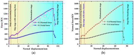
Figure 8.
Comparison of normal displacement-normal load/axial force curves of the ACC and anchor cable: (a) Φ21.8 mm anchor cable; (b) Φ21.8 mm ACC.
The greatest difference between the two structures was observed in the second (slip) stage. For the anchor cables, the slip stage corresponded to the decreasing gap between the reserved hole in the concrete block and the anchor cable. For the ACC, the slip stage included the following two processes: (1) the gap between the reserved hole in the concrete block and the anchor cable decreased, and (2) the concrete block and the C-shaped tube interacted. The tube was gradually compressed until it closed and tightly wrapped the anchor cable.
Figure 9 shows variations in the normal force, axial force, and normal displacement of the anchor cable and the ACC under the normal load action.
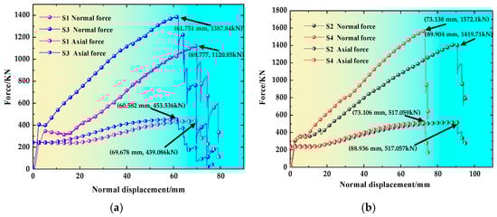
Figure 9.
Comparison of tensile shear test results between anchor cables and ACC: (a) Φ21.6 mm anchor cable & ACC; (b) Φ21.8 mm anchor cable & ACC.
It can be observed from Figure 9 that when breaking occurred under the normal load, the axial ultimate bearing capacity of the ACC with the Φ21.6 mm anchor cable increased by 3.29% compared with the Φ21.6 mm anchor cable alone, while the respective normal ultimate bearing capacity increased by 23.82%. The ACC’s axial ultimate bearing capacity with the Φ21.8 mm anchor cable increased slightly compared with the Φ21.8 mm anchor cable alone, while the normal ultimate bearing capacity increased by 10.73%. In addition, the initial shear stiffness of the ACC with Φ21.6 mm and Φ21.8 mm anchor cables increased by 22 and 37%, respectively, compared with the anchor cables alone.
As analyzed above, the normal bearing capacity of the ACC was improved dramatically compared to anchor cables alone.
4. Numerical Simulation of ACC
The case study was the Shuangliu Coal Mine located northwest of Lingshang Village of Lvliang City, Shanxi Province, China, with a ground elevation of 778–920 m. The #318 gas extraction roadway lies west of the #318 transport roadway and east of the #320 material roadway. The #381 gas extraction roadway has a width of 5 m and a height of 3.8 m. The coal seam from which gas is extracted via this roadway is the #(3 + 4) coal seam at the top of the lower Shanxi Formation, with an average thickness of 3.8 m. According to the working data, the surrounding rocks of the #318 gas extraction roadway are primarily composed of mudstone, fine sandstone, and medium sandstone. More details on the surrounding rock parameters are given in Table 2.
Table 2.
Lithology of #318 gas extraction roadway-surrounding rocks.
The original support scheme of the #318 extraction roadway is shown in Figure 10. The roof is supported by Φ20 × 2400 mm bolts combined with two W-shaped steel belts; the ribs are supported by Φ20 × 2000 mm bolts, plus a W-shaped guard plate placed vertically, and the anchor cable is made of Φ17.8 mm × L6400 mm steel strands. The first row is 1100 m from the roadway centerline. In the second row, one cable is arranged in the middle of the roadway, and other cables are laid with a spacing of 1000 m.
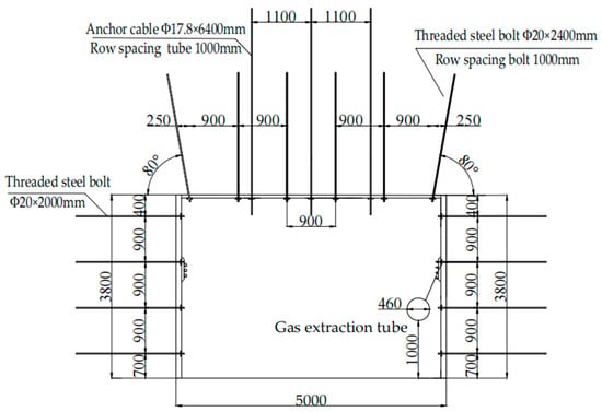
Figure 10.
The original support layout of the #318 extraction roadway.
4.1. Analysis of Damage Features of Surrounding Rocks
According to the field survey, the #318 gas extraction roadway underwent significant deformation. Some photos were taken (Figure 11), displaying the following features of deformation failure in the roadway:
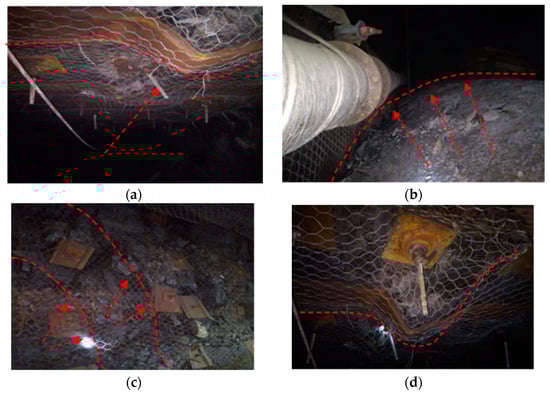
Figure 11.
Photos of deformation failure of the roadway: (a) roof breakage; (b) severe floor heave; (c) severe rib deformation; (d) W-shaped steel belt bending.
(1) The roof was significantly fractured, and the metal net caught the falling rock pieces. The W-shaped steel belts were bent in a wave-like manner; the two ribs were severely deformed, and the bolt trays became embedded; the floor heave was severe. The closer to the working face, the larger the floor deformation.
(2) Some roof bolts and cables were dislocated. The field survey showed that nearly all bolts and cables underwent shear failure. Photos of the fractures of bolts and cables are shown in Figure 12.
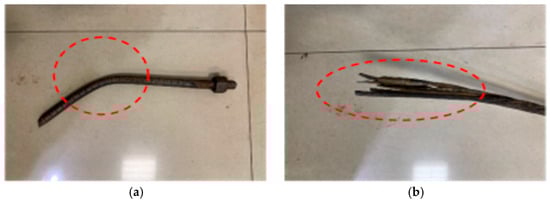
Figure 12.
Photos of the bolt and anchor cable breakage in the roadway: (a) bolt shearing; (b) anchor cables damaged by shearing.
According to related data, supports are usually densified in coal mines to counter shear failure. However, this approach achieves poor support performance and interferes with the subsequent reinforced support. Based on the actual engineering conditions of the Shuangliu Coal Mine, the main influencing factors of roadway stability were identified:
(1) The rock masses and coal seam in the #318 gas extraction roadway have limited strength. In addition, due to the action of high geostatic stress, the surrounding rocks in the ribs and corners underwent significant deformation. Severe rib failure further reduced the support offered by the roof. Stress concentration occurred at the roadway’s roof corners, severely threatening the surrounding rock stability.
(2) The large deformation of the #318 gas extraction roadway was related to the original support design and the choice of support materials. The original support design does not fully account for the features of the surrounding rocks. Moreover, the support materials selected did not have sufficiently high shear strength. For these reasons, the support system only partially fulfilled its functions.
4.2. ACC Scheme for the #318 Gas Extraction Roadway
In this study, we proposed an ACC scheme for the #318 gas extraction roadway in the Shuangliu Coal Mine, containing the following additions to the original support scheme.
In the roof, ribs, and floor corners, the ACC with Φ21.8 mm anchor cables was installed along with arc-shaped high-strength cable trays for reinforced support. Two rows of ACC were installed on the roof, with a spacing of 1000 mm. Two rows of ACC were installed 500 mm from the rib top and 150 mm from the rib bottom. One row of ACC was installed in the middle of the rib, and the arrangement was symmetrical in the two ribs, with a spacing of 1000 mm. One row of ACC was arranged in the east and west floor corners, respectively, with a spacing of 1000 m. The support scheme using an ACC is shown in Figure 13. Using an 8.4 m-long anchor cable as an example, its cost was compared to that of the ACC, as shown in Table 3. The former was $44.91, versus ACC’s $46.95, implying a 4.5% cost increase for a 10–25% improvement in shear resistance, thus, substantiating the ACC usage feasibility.
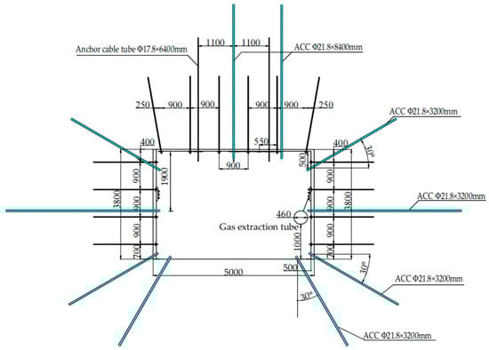
Figure 13.
Schematic diagram of ACC in the roadway cross-section.
Table 3.
Costs of an 8.4 m-long anchor cable and ACC.
4.3. Numerical Analysis of Deformation and Failure Mechanism of the #318 Gas Extraction Roadway
The FLAC3D commercial software (FLAC 3D 5.0., ITASA, USA) package was used for modeling, based on the actual engineering situation in the #318 gas extraction roadway of the Shuangliu Coal Mine. The stress state was simulated under the original and ACC schemes after excavating the #318 gas extraction roadway. The bolts and cables were simulated using CABLE elements, and the C-shaped tubes were simulated using PILE elements. Modeling was performed based on field data. The surrounding rock parameters of the roadway are listed in Table 4.
Table 4.
Characteristic parameters of roadway surrounding rocks.
The numerical simulation model had dimensions of 30 m × 30 m × 15 m (length × width × thickness); the roadway model had a size of 5000 mm × 3800 mm. The overall model and the roadway were symmetrical on both sides, as shown in Figure 14. Displacement constraints were imposed on the four sides and the bottom of the model. A vertical distributed stress of 12.4 MPa was applied to the model’s top to simulate the overlying load. The lateral pressure coefficient was taken as 1.2.
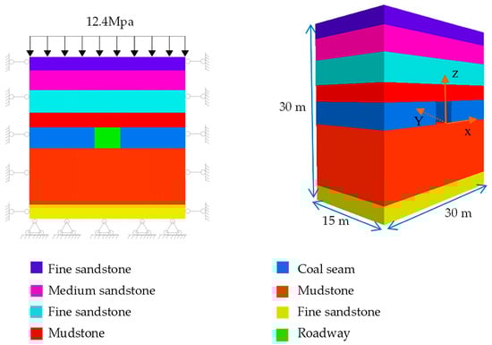
Figure 14.
Numerical simulation model.
Figure 15 shows the distributions of vertical and horizontal stresses in the roadway surrounding rocks under the original support scheme and the ACC system calculated by numerical simulation: those in Figure 15a,b were compared against those in Figure 15c,d. The following findings were made:

Figure 15.
Stress distributions under the original (a,c,e,g) and ACC (b,d,f,h) support schemes.
(1) The area of stress concentration decreased dramatically under the ACC scheme compared to the original support scheme. The above result indicated that the ACC scheme effectively reduced stress concentration and crack generation, thereby contributing to the surrounding rock stability of the roadway.
(2) In the floor, roof, and two ribs, the area of stress disturbance under the ACC scheme was smaller than that under the original support scheme. Under the original support scheme, the area of stress disturbance in the two ribs was within 4.8 m from the roof and floor and 2.3 m from the two ribs. The area of stress disturbance in the two ribs was within 4.7 m from the roof and floor and within 1.7 m from the two ribs under the ACC scheme. The area of stress disturbance has been marked with a red circle in the Figure 15. It is easy to see that the bearing capacity of the surrounding rocks was more fulfilled under the ACC scheme.
(1) The minimum horizontal stresses in the ribs under the original and ACC schemes were 0.03 and 0.81 kN, respectively, proving that the ACC scheme effectively improved the bearing capacity of the surrounding rocks in the ribs, thereby enhancing the surrounding rock stability.
(2) Compared with the original support scheme, the tensile stress in the surrounding rocks decreased by 4.1% under the ACC scheme. The latter was qualified as a complementary support structure for surrounding rocks, and conducive to forming stable zones.
As shown in Figure 16, the ACC scheme effectively reduced the surrounding rock displacements in the vertical and horizontal directions. In the vertical direction, the roof-to-floor convergences were 17.01 and 15.53 cm under the original and ACC schemes, respectively, differing by 9.53%. As shown in Figure 16a,b,e,f, the rib-to-rib convergence reached 22.27 and 17.80 cm in the horizontal direction under the original and ACC schemes, respectively. Compared with the original scheme, the rib deformation decreased by 25.11% under the ACC scheme, which was a remarkable reduction, as shown in Figure 16c,d,g,h.
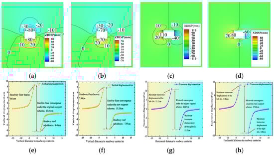
Figure 16.
Displacement distributions under the original (a,c,e,g) and ACC (b,d,f,h) support schemes.
As analyzed above, the ACC scheme outperformed the original scheme in controlling the deformation of the floor, roof, and two ribs.
Figure 17 shows the distribution ranges of the plastic zone obtained by numerical simulation under the original and ACC schemes. A comparison between Figure 17a,b shows that the plastic zone in the surrounding rocks was much smaller under the ACC scheme than under the original support scheme. According to the numerical simulation, the volume of the plastic zone in the surrounding rocks decreased by 5.01% under the ACC scheme compared to that under the original support scheme.
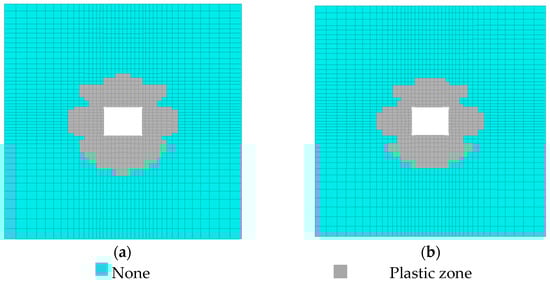
Figure 17.
Distributions of plastic zones in the two support schemes: (a) the original support scheme; (b) ACC support scheme.
5. Field Monitoring of the ACC in the #318 Extraction Roadway
To validate the performance of the ACC scheme, we conducted field tests within a length of approximately 300 m in the #318 gas extraction roadway. The ACC scheme was applied to support tests in the roadway. Monitoring of the two ribs, floor, and roof was performed for 55 days, using the cross-shaped point arrangement method. The field monitoring data are shown in Figure 18.

Figure 18.
Field monitoring data in the #318 extraction roadway using ACC.
It can be observed from the field monitoring data in Figure 18 that from the start of monitoring to day 11 of monitoring, the roof-and-floor and rib-to-rib deformation rates were the highest at monitoring points 1 and 2. The roof-and-floor and rib-to-rib deformations at monitoring points 1 and 2 increased by 25 and 28 mm versus 23 and 26 mm, respectively. From day 25 of monitoring onward, the above deformations slowly increased. After 55 days of monitoring, the maximum roof-and-floor and rib-to-rib deformations were 40 and 48 mm at monitoring point 1, respectively, reaching 39 and 49 mm at monitoring point 2. Thus, the ACC scheme effectively controlled the deformation rate of the surrounding rocks in the roadway. The deformation law observed by field monitoring was consistent with that estimated by numerical simulation. This proved that the proposed ACC scheme provided adequate shear resistance during the engineering process, which enhanced the ability of the surrounding rocks to withstand shear loads. The ACC scheme achieved a good application effect.
6. Conclusions
(1) The ACC is a novel support member that can withstand transverse loads and resolve the problem of poor shear resistance when using anchor cables with a high prestress level. The slip resistance offered to the sliding surrounding rocks is provided by the following four components: (i) surrounding rocks themselves, (ii) response to the prestress, (iii) the C-shaped tube, and (iv) the converted pinning effect.
(2) The performed double-shear tests showed that under the same prestress level, the axial ultimate bearing capacity of the ACC with the Φ21.6 mm anchor cable increased by 23.82% compared to the Φ21.6 mm anchor cable alone; the normal ultimate bearing capacity increased by 10.73%. In addition, compared with anchor cables alone, the two types of ACC increased the initial shear stiffness by 22% and 37%, respectively, indicating that the ACC outperformed anchor cables alone in shear resistance.
(3) The numerical simulation using FLAC3D proved that the proposed ACC scheme reduced the stress concentration. The volume of the plastic zone in the surrounding rocks decreased by 5.01%, compared to the original support scheme. The ACC scheme effectively controlled the deformation displacement of the roof, floor, and two ribs. The maximum roof-to-floor and rib-to-rib convergences under the ACC scheme were 15.53 and 17.80 cm, respectively, implying reductions of 9.53 and 25.11%, compared to the original scheme. The above results proved that the ACC system fully fulfilled its shear-bearing capacity and ensured the surrounding rock stability of the #318 gas extraction roadway taken as a case study.
(4) Field monitoring showed that the ACC reduced the deformation of the floor, roof, and two ribs, and the deformation rate of the surrounding rocks, in a real engineering scenario. According to the 55-day monitoring, the maximum roof-and-floor and rib-to-rib deformations were 40 and 49 mm, respectively. This indicated a good application effect of the ACC in field tests and the ability of the ACC to provide extra shear resistance when added to prestressed bolts and cables.
Author Contributions
Conceptualization, L.L. and X.-S.K.; methodology, X.-S.K.; software, W.Y.; validation, L.L., X.-S.K. and W.Y.; formal analysis, L.L.; data curation, J.-W.H.; writing—original draft preparation, L.L.; writing—review and editing, X.-S.K.; supervision, Z.-E.W. All authors have read and agreed to the published version of the manuscript.
Funding
The study was supported by the National Natural Science Foundation of China (Grant No. 52274148), the Fundamental Research Funds for the Central Universities (Grant No. 2021YQLJ08) and the Research project on anchor cable and C-shaped tube support technology for coal roadway in Shuangliu Coal Mine (Grant No. 2021207010028).
Data Availability Statement
Not applicable.
Conflicts of Interest
The authors declare no conflict of interest.
References
- Wang, J.Y.; Wang, F.T.; Zheng, X.G. Stress Evolution Mechanism and Control Technology for Reversing Mining and Excavation under Mining-Induced Dynamic Pressure in Deep Mine. Geofluids 2022, 2022, 4133529. [Google Scholar] [CrossRef]
- Shan, R.; Tong, X.; Huang, P.; Yuan, H.; Bao, Y.; Liu, N. Research on the anchor cable combined with the c-shaped tube and the mechanical properties. Rock Soil Mech. 2022, 43, 602–614. [Google Scholar] [CrossRef]
- Kang, H.P. Seventy years development and prospects of strata control technologies for coal mine roadways in China. Chin. J. Rock Mech. Eng. 2021, 40, 1–30. [Google Scholar] [CrossRef]
- Ma, L.Q.; Jin, Z.Y.; Liang, J.M.; Sun, H.; Zhang, D.S.; Li, P. Simulation of water resource loss in short-distance coal seams disturbed by repeated mining. Environ. Earth Sci. 2015, 74, 5653–5662. [Google Scholar] [CrossRef]
- Xie, H.P.; Gao, M.Z.; Zhang, R.; Peng, G.Y.; Wang, W.Y.; Li, A.Q. Study on the Mechanical Properties and Mechanical Response of Coal Mining at 1000 m or Deeper. Rock Mech. Rock Eng. 2019, 52, 1475–1490. [Google Scholar] [CrossRef]
- Wang, Q.; Jiang, B.; Pan, R.; Li, S.C.; He, M.C.; Sun, H.B.; Qin, Q.; Yu, H.C.; Luan, Y.C. Failure mechanism of surrounding rock with high stress and confined concrete support system. Int. J. Rock Mech. Min. Sci. 2018, 102, 89–100. [Google Scholar] [CrossRef]
- Li, J.Z.; Kang, H.P.; Gao, F.Q.; Lou, J.F. Analysis of bolt support stress field and bolt support effect under in-situ stress field. J. China Coal Soc. 2020, 45, 99–109. [Google Scholar] [CrossRef]
- Liu, W.; Zhang, Z.X.; Fan, J.Y.; Jiang, D.Y.; Li, Z.Y.; Chen, J. Research on gas leakage and collapse in the cavern roof of underground natural gas storage in thinly bedded salt rocks. J. Energy Storage 2020, 31, 101669. [Google Scholar] [CrossRef]
- Hu, B.; Kang, H.P.; Lin, J. Comparison and application of high prestress and intensive support system in close, soft and cracked roadway support. Adv. Mater. Res. 2012, 524–527, 29–35. [Google Scholar] [CrossRef]
- Zhao, X.; Li, H.; Zhang, S.; Yang, X. Stability analyses and cable bolt support design for A deep large-span stope at the hongtoushan mine, China. Sustainability 2019, 11, 6134. [Google Scholar] [CrossRef]
- Bai, Y.; Shan, R.L.; Wu, Y.X.; Sun, P.F. Development and Application of a New Triaxial Testing System for Subzero Rocks. Geotech. Test. J. 2021, 44, 1327–1349. [Google Scholar] [CrossRef]
- Liu, X.W.; Chen, J.X.; Liu, B.; Luo, Y.; Zhu, Y.G.; Huang, X. Large Deformation disaster mechanism and control technique for deep roadway in faulted zone. Front. Earth Sci. 2022, 10, 826661. [Google Scholar] [CrossRef]
- Yuan, H.H.; Shan, R.L.; Su, X.G. Deformation characteristics and stability control of a gateroad in fully mechanized mining with large mining height. Arab. J. Geosci. 2018, 11, 767. [Google Scholar] [CrossRef]
- Kang, H.P.; Wang, G.F.; Jiang, P.F.; Wang, J.C.; Zhang, N.; Jing, H.W.; Huang, B.X.; Yang, B.G.; Guan, X.M.; Wang, Z.G. Conception for strata control and intelligent mining technology in deep coal mines with depth more than 1000 m. J. China Coal Soc. 2018, 43, 1789–1800. [Google Scholar] [CrossRef]
- He, M.C.; Li, C.; Gong, W.L.; Wang, J.; Tao, Z.G. Support principles of NPR bolts/cables and control techniques of large deformation. Chin. J. Rock Mech. Eng. 2016, 35, 1513–1529. [Google Scholar] [CrossRef]
- Wu, X.; Jiang, Y.; Wang, G.; Gong, B.; Guan, Z.; Deng, T. Performance of a New Yielding Rock Bolt under Pull and Shear Loading Conditions. Rock Mech. Rock Eng. 2019, 52, 3401–3412. [Google Scholar] [CrossRef]
- Tahmasebinia, F.; Yang, A.; Feghali, P.; Skrzypkowski, K. A Numerical Investigation to Calculate Ultimate Limit State Capacity of Cable Bolts Subjected to Impact Loading. Appl. Sci. 2023, 13, 15. [Google Scholar] [CrossRef]
- Tahmasebinia, F.; Yang, A.; Feghali, P.; Skrzypkowski, K. Structural Evaluation of Cable Bolts under Static Loading. Appl. Sci. 2023, 13, 1326. [Google Scholar] [CrossRef]
- Ivan, S.; Svitlana, S. Numerical Studies of Floor Heave Control in Deep Mining Roadways with Soft Rocks by the Rock Bolts Reinforcement Technology. Adv. Civ. Eng. 2023, 2023, 2756105. [Google Scholar] [CrossRef]
- Pyon, K.N.; Son, K.S.; Han, U.C. Numerical Simulation Study on Influence of a Structural Parameter of D Bolt, an Energy-Absorbing Rock Bolt, on its Stress Distribution. Adv. Civ. Eng. 2023, 2023, 3276832. [Google Scholar] [CrossRef]
- Rao Karanam, U.M.; Dasyapu, S.K. Experimental and numerical investigations of stresses in a fully grouted rock bolts. Geotech. Geol. Eng. 2005, 23, 297–308. [Google Scholar] [CrossRef]
- Li, C.C. Field observations of rock bolts in high stress rock masses. Rock Mech. Rock Eng. 2010, 43, 491–496. [Google Scholar] [CrossRef]
- Li, X.; Aziz, N.; Mirzaghorbanali, A.; Nemcik, J. Behavior of fiber glass bolts, rock bolts and cable bolts in shear. Rock Mech. Rock Eng. 2016, 49, 2723–2735. [Google Scholar] [CrossRef]
- Li, X.; Yang, G.; Nemcik, J.; Mirzaghorbanali, A.; Aziz, N. Numerical investigation of the shear behaviour of a cable bolt in single shear test. Tunn. Undergr. Space Technol. 2019, 84, 227–236. [Google Scholar] [CrossRef]
- Mirzaghorbanali, A.; Rasekh, H.; Aziz, N.; Yang, G.; Khaleghparast, S.; Nemcik, J. Shear strength properties of cable bolts using a new double shear instrument, experimental study, and numerical simulation. Tunn. Undergr. Space Technol. 2017, 70, 240–253. [Google Scholar] [CrossRef]
- Aziz, N.; Rasekh, H.; Mirzaghorbanali, A.; Yang, G.; Khaleghparast, S.; Nemcik, J. An experimental study on the shear performance of fully encapsulated cable bolts in single shear test. Rock Mech. Rock Eng. 2018, 51, 2207–2221. [Google Scholar] [CrossRef]
Disclaimer/Publisher’s Note: The statements, opinions and data contained in all publications are solely those of the individual author(s) and contributor(s) and not of MDPI and/or the editor(s). MDPI and/or the editor(s) disclaim responsibility for any injury to people or property resulting from any ideas, methods, instructions or products referred to in the content. |
© 2023 by the authors. Licensee MDPI, Basel, Switzerland. This article is an open access article distributed under the terms and conditions of the Creative Commons Attribution (CC BY) license (https://creativecommons.org/licenses/by/4.0/).