1. Introduction
In recent years, intelligent substations have developed rapidly. Intelligent substations are based on the intelligent upgrading of traditional substations, which introduce wireless sensor network technology into the existing systems to achieve seamless man-machine connectivity. Intelligent substations can greatly improve the efficiency of operation and overhaul, thus reducing the labor intensity of electric power workers.
In intelligent substations, there are not only wired communication methods such as optical fiber and secondary control cable but also wireless communication methods using short-distance wireless communication technology. Among them, wireless Internet of things technology plays an increasingly important role in substations [
1,
2,
3,
4,
5,
6,
7,
8]. In intelligent substations, wireless network equipment is often located near primary equipment, and switching operations always produce a complex and strong electromagnetic field, which makes the electromagnetic environment of wireless equipment extremely harsh [
9,
10,
11,
12,
13,
14].
With the development of electric internet of things technology, a large number of wireless network communication devices are urgently needed in substations, which are the core hubs of a power system. Different from the public wireless network [
15,
16], the electromagnetic environment in the substation is complex and changeable. There is not only the stable electromagnetic environment generated around the substation during normal operation but also the transient electromagnetic effect caused by the sharp change of the surrounding transient electromagnetic field caused by switching operation. At present, all UHV AC electric power transmissions in our country have been using gas-insulated switchgear equipment. With the acceleration of power grid construction, their voltage levels have gradually increased so that a strong transient electromagnetic field will be produced when some switching devices such as circuit breakers, disconnecting switches and grounding switches are operated, which will cause electromagnetic disturbance to electrical equipment and communication cables outside GIS.
In the intelligent substation, the sink node is the central device of the whole wireless communication network, which is responsible for collecting the information perceived by the sensor unit and uploading it to the server terminal device. For the equipment of a wireless network sink node in an intelligent substation, the meaning of EMC is: the equipment or system of a wireless network sink node can work normally in its electromagnetic environment; the electromagnetic interference they emit will not affect the normal operation of other things in the environment. They will not produce electromagnetic interference in the common electromagnetic environment and can complete their respective functions and tasks. However, the complex transient space electromagnetic field in the substation will disturb the cable core of the sink node by the coupling mode of the far field and the near field, and finally, the amount of intrusion into the device port may cause abnormal work of the device or even damage.
The coupling problem between electromagnetic fields and transmission lines has been a hot topic for researchers at home and abroad. Many scholars have studied the field-line coupling problem based on multi-conductor transmission line theory [
17], Taylor’s field-transmission line model [
18], Agrawal’s field-transmission line model [
19] and Rachidi’s field-transmission line model [
20] are used to analyze the field-line coupling problem. A multi-conductor transmission line model is established, and the radiation sensitivity of twisted pairs above the ground under a non-uniform/uniform electromagnetic field is studied [
21,
22,
23,
24,
25]. However, the coupling characteristics between the transient electromagnetic field of the wireless network equipment and the interconnection cables of the sink nodes have not been studied. In addition, in the field of measurement and experimental research on the induced current of communication cable core, there is a lack of research on the measurement of the disturbance voltage of intelligent substation transient space electromagnetism to the new type of communication cable of wireless network equipment.
In this paper, several intelligent substations are investigated, the networking methods of wireless network equipment in substations are summarized and analyzed, the transient electric field and the common-mode induced current of the cables at the sink nodes in a 110 kV GIS intelligent substation under different operating conditions are measured, and the time-domain and frequency-domain analysis are carried out. A transient near-field line coupling model is established by using the simulation software. The work of this paper can contribute to the reliable operation of the intelligent substation sink node equipment.
2. Analysis of Intelligent Substation Net-Work and Coupling Path
In the complex and harsh electromagnetic environment of an intelligent substation, wireless network equipment may be affected, which will affect the quality of communication and cause code errors and packet loss. In serious cases, it may damage the equipment, resulting in the normal and reliable operation of the entire wireless network system. The electromagnetic compatibility problem of wireless network equipment is becoming more and more serious, which needs to be solved urgently. As the central equipment of the whole wireless sensor network, on the one hand, the sink node needs to communicate with the wireless sensor unit by wireless means. On the other hand, it is necessary to transmit the information collected by the wireless sensor unit to the access node by wire. The reliable and normal operation of the wireless sensor unit is the key link of the wireless sensor network, playing a crucial role in wireless sensor network communications.
2.1. Intelligent Substation Network
The communication protocol of the wireless network device studied in this paper is LORA, which is a kind of Low Power Wide Area Network (LPWAN). Using LPWAN technology can achieve long-distance and low-power communication, realize longer-distance communication and lower power consumption to the greatest extent, and save the cost of additional repeaters. Building a wireless private network through LoRa wireless communication technology mainly needs four parts, namely, a base station (or gateway), server, LoRa terminal and Internet of Things cloud. LoRa’s main frequency bands include 230, 470, 868, 915 MHz, etc. [
26,
27].
LoRa-based wireless communication features low cost, low power consumption, low delay, anti-interference and long-distance transmission. The technical features are as follows: (1) The standard followed by this technology is IEEE802.15.4g; (2) Its working frequency is 230 MHz and 433 MHz; (3) Its transmission distance is related to the geographical environment and generally, it can reach 2~5 km in towns and 15 km; in the suburbs; (4) Its modulation mode is based on spread spectrum technology, that is, it adopts linear modulation spread spectrum (CSS), and has the capability of forward error correction (FEC); (5) Its transmission rate ranges from tens to hundreds of Kbps, and the lower the transmission rate, the longer the transmission distance; (6) Its security technology is AES128 encryption, which makes the data transmission process more secure and reliable.
Based on the field investigation and analysis of several smart substations, it is found that due to the different voltage levels and internal structures of smart substations, the networking methods of the wireless network devices used in the smart substations are also different.
In the 110 kV GIS intelligent substation network mode, as shown in
Figure 1 below, the wireless sensor unit transmits the perceived data to the host through the wireless mode. After the host receives the information perceived by the wireless sensor unit, the data is uploaded to the serial port server by the wired way. The serial port server sends the data to the security agent module through the Ethernet cable for the data security processing, then the security agent module sends the processed data to the Customer Premise Equipment (CPE) via Ethernet cable, and the CPE uploads the processed data to the base station via wireless mode. Finally, the data is uploaded to the terminal server by the optical fiber from the base station. This kind of network is relatively complex, using lots of equipment, and there are also many types and quantities of cables used.
Although different types of intelligent substations have different networking methods, the function of sink node devices in intelligent substations is the same for wireless communication networks. The sink node is the relay and convergence device of sensor data in the Internet of things (IoT), the main communication node of the wireless sensor in the IOT sensing layer, constituting the communication framework of the whole sensor network. The sensing unit transmits the perceived state information of the electric power equipment to the gathering node equipment through the wired or wireless communication mode, different types of sink node devices communicate with each other through wire communication, and the information is summarized, encrypted and processed. Finally, the sink node device uploads the information to the terminal through wireless communication.
According to the investigation results, there are three types of converged node cables in intelligent substations: Shielded and non-shielded cables used for communication between wireless network communication devices; A coaxial cable for communication between a sink node and an external antenna; a power cord for supplying power to a sink node device.
2.2. Coupling Path Analysis
Only the sensing node and primary equipment are installed on the surface of the primary equipment in the wireless network communication equipment, and the convergence node equipment and base station are not directly connected with the primary equipment. The wireless network communication equipment is different from the traditional communication equipment and communicates with each other as an independent system. The convergence node equipment is installed in the intelligent component cabinet and has no communication connection with the traditional secondary equipment. Therefore, the directly conducted harassment from the primary equipment by the convergence node equipment can be neglected.
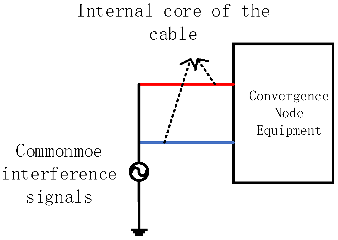
There are many kinds and amounts of cables used in the gathering node equipment of intelligent substations, in which the space is relatively small, the strong transient electromagnetic disturbance caused by switching operation can be radially coupled into the power supply and data lines of the sink node, as shown in
Figure 2, which may affect the normal operation of the converging node, even cause equipment damage.
There are two types of Ethernet cables used by sink node devices, namely shielded and non-shielded. The standard used is YD/T1019-2013, which has eight cores and commonly uses a pair of insulated wires in accordance with a certain density of mutual twisted manner to reduce the outside electromagnetic wave interference on the signal, so also known as twisted pair. Twisted-pair wrapped in the insulation skin inside eight signal lines, of which four signal lines are for data transmission and reception, the other four signal lines as a backup. The strong transient space electromagnetic field produced by the intelligent substation during switching operation is coupled to the shielding layer of the shielded network wire, which forms the amount of disturbance. This part of the disturbance will generate induced voltage and induced current in the inner core wire through the transfer admittance and transfer impedance between the shield layer and the inner core wire and then transmit to the communication port of the sink node equipment through the cable, which will cause error code, garbled code, quality degradation of the transmission signal and could even damage the internal integrated circuit.
The 12 V and 2 A DC power supply is used for the equipment of the sink node. The power supply line consists of two wires, which are connected to the power module respectively. Each wire is made up of two parts: a PVC insulating layer and a conductor, one of the power lines is the positive pole of the power supply, and the other is the negative pole of the power supply. Because the power line has no shielding layer, the transient electromagnetic field will directly couple with the inner core line to produce induced voltage and induced current and then invade the power port of the terminal equipment, which will affect the power port.
The coaxial cable used by the sink node device completes the communication between the sink node and the external antenna. Coaxial cable consists of a conductor, insulation layer, copper wire braided shield layer and sheath. The induced voltage and current generated by the coupling of the transient space electromagnetic field in the inner core of the coaxial cable in the intelligent substation are transmitted to the antenna port of the sink node equipment. Therefore, the wireless communication of sink node equipment is affected.
3. Analysis of Test Results of Transient Space Electromagnetic Field under Different Operating Conditions
3.1. Test System and Test Content
In order to study the amount of disturbance caused by the coupling of cables in the sink node in the intelligent substation during the switching operation, in this paper, the transient space electromagnetic field and common-mode disturbance current of communication cables and power supply lines of sink nodes are measured in 110 kV GIS intelligent substation under different operating conditions.
In order to make the test more targeted, the transient space electric field near the sink node device is tested, and the transient induced current of the communication line and the power supply line of the sink node equipment is measured in the online monitoring cabinet of the GIS room of 110 kV GIS intelligent substation.
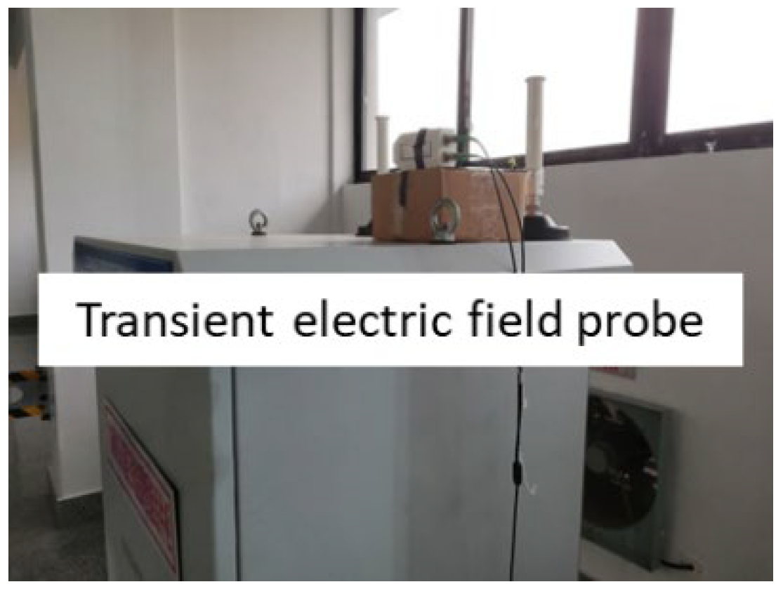
The device is installed in the intelligent component cabinet in the GIS room. The transient electric field probe is arranged above the cabinet where the sink node equipment is located, and the near-field source of the cable of the sink node cable is tested, as shown in
Figure 3. The current probe is clamped on the power and communication lines of the sink node equipment, and the transient disturbance current of the sink node cable is obtained by testing, as shown in
Figure 4.
3.2. Analysis of Test Results of Transient Space Electromagnetic Field under Different Operating Conditions
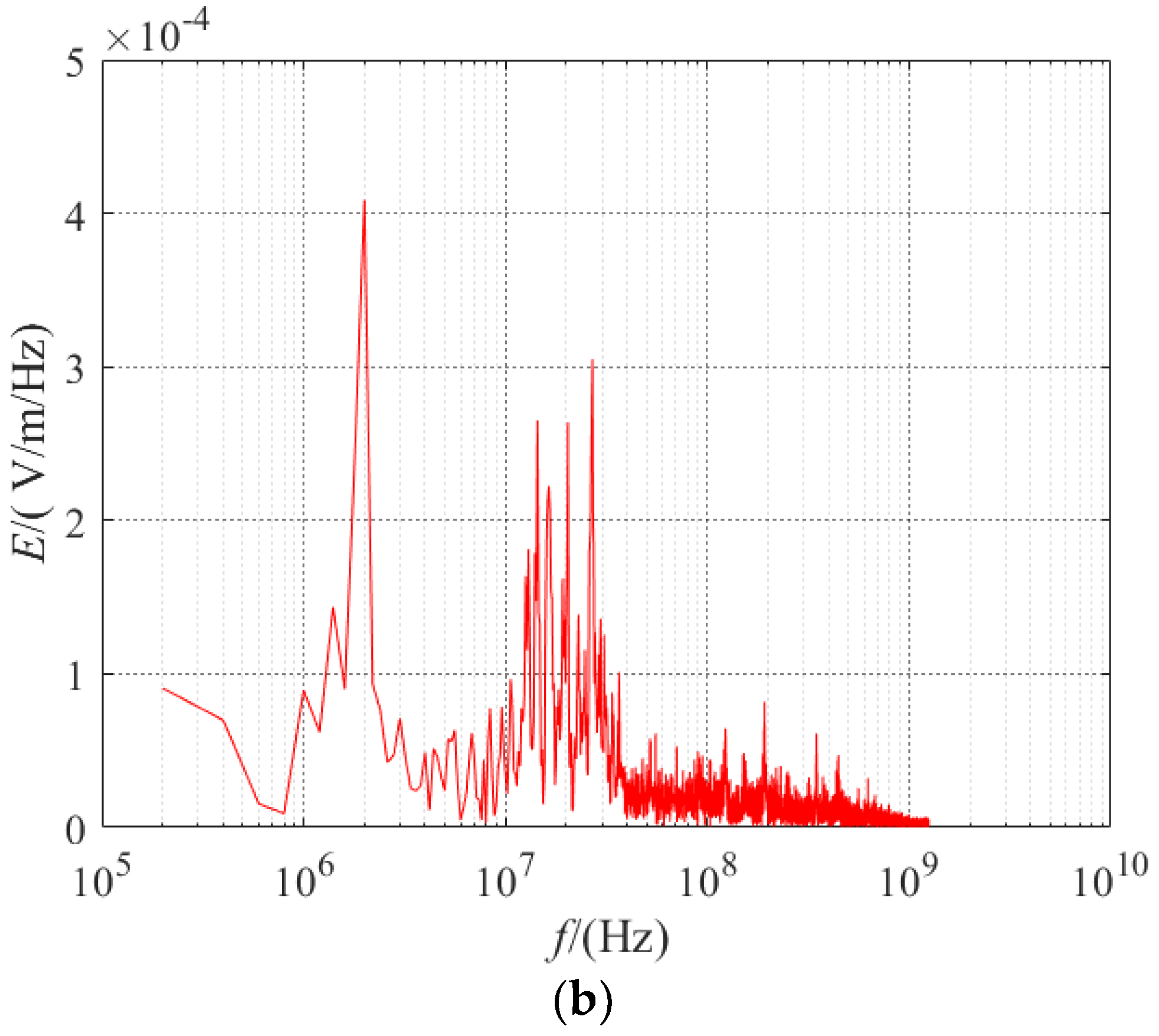
In the 110 kV GIS intelligent substation, the disconnecting switch is opened and closed, and the bus tie circuit breaker is operated. In this paper, the transient electric fields near the sink nodes are measured in different operation modes, and the data are analyzed and analyzed in the time domain and frequency domain. The typical transient electric field waveforms in the time domain and frequency domain under different operation modes and at different test locations are shown in
Figure 5,
Figure 6 and
Figure 7, respectively.
The transient electromagnetic disturbance caused by the switching operation of the GIS substation is a damped oscillation wave. Its single pulse characteristic parameters are as follows.
Peak/peak value: the difference in amplitude between the positive peak and the negative peak of the bipolar damped oscillation wave. When the positive and negative peaks are far apart, the peak value can be used instead.
Rise time tr: The time for the first single pulse instantaneous value to rise from 10% to 90%.
Duration td: The time from the beginning to the end of a single pulse.
Main frequency distribution DF: In the frequency band range, the frequency point whose amplitude is 6 dB higher than other frequency components responds to the distribution of the main energy of the transient wave in the frequency domain.
Band range BW: using the relative criterion, i.e., the frequency component above the background noise.
The time-domain and frequency-domain statistical analysis of some of the data obtained from the tests are shown in
Table 1 below. The single pulse transient electric field waveform of 110 kV GIS intelligent substation caused by isolating switch closing operation, isolating switch opening operation, and circuit breaker closing operation is a damping oscillation wave, the duration of which is about 1~3 μs. The peak value of the transient space electric field caused by the switch closing operation is about 10 kV/m, and the rising edge is NS class. The peak value of the transient space electric field caused by the circuit breaker closing operation is 4.88 kV/m, and the duration is 1.41 μs. Compared with the switch closing operation, the electromagnetic disturbance caused by the switch closing operation is more intense.
Based on the analysis of the test results of the transient electromagnetic disturbance near the installation location of the sink node of the intelligent substation, the main frequency of the transient space electric field monopulse waveform caused by bus side isolating switch closing operation, line-side isolating switch closing operation and circuit breaker closing operation in 110 kV GIS intelligent substation is about 3 MHz, 10 MHz and 30 MHz respectively, which is consistent with the IEC61000-4-18 standard. However, there are other frequency components not reflected in the standard, such as the main frequency up to 50 MHz; Compared with the operation of the disconnector, the frequency spectrum of circuit breaker operation is more abundant.
3.3. Analysis of the Induced Current of the Sink Node Cables under Different Operating Conditions
When the 110 kV GIS intelligent substation is engaged in busbar-side isolating switch closing operation, lineside isolating switch operation and circuit breaker operation, the common-mode induced current data of the communication line and power line of the sink node are obtained.
Figure 8 and
Figure 9 show the time-domain and frequency-domain waveforms of the common-mode induced current of the sink node cables during the isolation switch closing operation, corresponding to the transient space electric field of the operation type in
Figure 5 and
Figure 6, respectively. Thus, the induced current of the cable in the sink node under near-field excitation is obtained.
Common-mode interference: harassment acting simultaneously on the input of sensitive equipment, as shown in
Figure 8.
The common-mode induced currents of the above-mentioned sink node cables under different operation types are analyzed in the time domain, and the parameters of the common-mode currents are shown in
Table 2. The test results show that when the isolation switch of 110 kV GIS intelligent substation is switched off, transient electric field strength around the convergence node equipment is 10.5 kV/m, the common-mode induced current peak values of communication line and power line are 0.8 A and 0.8 A; When the isolation switch is switched on, transient electric field strength around the convergence node equipment is 3.67 kV/m, the peak value of common-mode induced current of communication line and the power line is 0.15 A and 0.025 A; While the peak value of common-mode induced current of the communication line and power line is 0.025 A and 0.03 A when the circuit breaker is operated. From the test results, it can be seen that both the transient electric field and the induced current waveform of the convergence node cable are damped oscillation waves; the higher the electric field strength, the higher the peak induced current of the convergence node cable, which indicates that the induced current of the cable is indeed associated with the transient harassment generated by the operation of the disconnect switch.
Under the same operation type, the amplitude of the common-mode current on the communication line of the sink node is lower than that of the common-mode induced current on the power line. From the angle of cable structural characteristic, the shielding layer of the communication line can restrain part of the external electromagnetic disturbance, the shielded network line is adopted by the sink node communication line, and the unshielded cable is adopted by the power line, so the shielding layer of the communication line can suppress part of the external electromagnetic disturbance, and the coupling effect between the transient space electromagnetic field and the inner core wire of the communication line is reduced. In addition, the internal core wire of the sink node communication line adopts the structure of two twisted pairs, which can also restrain external electromagnetic disturbance. The transient electric field strength produced by the operation of the intelligent substation disconnector is higher than that produced by the operation of the circuit breaker, and the amplitude of common-mode induced current is higher in the communication line and power line of the sink node.
The frequency domain characteristics of the common-mode induced currents in the above-mentioned sink node cables under different operation types are shown in
Table 3 and
Table 4.
The test results show that when the isolation switch is operated, the main frequency of the induced current on the communication line and power line of the sink node is distributed at about 1 MHz, 3 MHz, 10 MHz and 30 MHz; When the circuit breaker is operated, the main frequency distribution of the induced current on the communication line and power line of the sink node is more complex than the operation of the isolation switch. The main frequency component of the induced current on the power line is more complex than that on the communication line because the structural characteristics of the communication line of the sink node can suppress some electromagnetic disturbances.
4. Sink Node Cable Near-Field Line Coupling Modeling Simulation Analysis
4.1. Simulation Model
In order to reveal the coupling mechanism of the transient spatial electromagnetic field in the intelligent substation to wireless network sink node cable disturbance, based on the theory of field-line coupling and the method of multi-conductor transmission line, this paper establishes the cable model of communication line and power line of sink node according to the cable type and structure in the intelligent substation in the CST software, as shown in
Figure 10 below, and the simulation model of field-line coupling is also established, which is shown in
Figure 11 below. The common-mode induced current of the sink node cable is calculated.
According to the equipment layout, cable direction and length of the intelligent substation sink node, a three-dimensional model with the same direction and length as the field sink node cable is established in the CST simulation software.
In the field test, the switch operating position of the intelligent substation is less than 1/6 wavelength (λ/2π) from the sink node cable, in which case the space electromagnetic field can be used as a near field. In this paper, a dipole antenna is established to simulate the near-field excitation source. The size of the dipole antenna is calculated according to the main frequency of the transient space electric field.
From the analysis of the characteristic parameters in the frequency domain of the space electric field measured above, it can be seen that the main frequency distribution of the space electric field is 27.84 MHz, 26.69 MHz, 29.76 MHz under different operation types, and these frequencies are in the IEC61000-4-18 standard in the vicinity of 30 MHz damping oscillations. Therefore, the size of the dipole half-wave dipole antenna is 5 m at 30 MHz frequency.
The measured space electric field is introduced into the antenna port of the near-field-line coupling model to simulate the coupling characteristics of the sink node cables in the near-field space. After setting up the excitation source and near-field-line coupling model, the corresponding field-line coupling equivalent circuit model is generated in CST software, and the probe is set up, as shown in
Figure 12 below.
4.2. Comparison and Analysis of Simulation and Measured Results
The transient electric field measured in a 110 kV GIS intelligent substation is used as the excitation source in the near-field coupling model, and the near field-line coupling model is established according to the types, lengths and trends of cables of the sink nodes in the field, then field-road collaborative simulation is carried out on the simulation model. The transient common-mode induced currents of the sink node wires and the power supply wires under near-field excitation are obtained by time-domain simulation. The results are shown in
Figure 13,
Figure 14 and
Figure 15 below. The common-mode current simulation results for sink node cables are shown in
Table 5 and
Table 6.
The simulation results of the communication line and the power line of the sink node are compared with the measured results. It is shown that the changes in the peak value and the amplitude value of the two lines are basically consistent in the time domain, and the peak value of the common-mode induced current is 0.8 A for both the network line and the power line; In the frequency domain, both of them are distributed around 10 MHz and 30 MHz of the main frequency. However, there are some differences between the simulation results and the measured ones. First, the excitation source of the simulation is the measured one-dimensional transient electric field waveform, while the transient electric field is actually three-dimensional. Secondly, the simulation model can not be completely consistent with the layout and structure of the substation. Third, the induced current of the sink node cable measured in the substation is the result of many kinds of complex electromagnetic disturbances, including near-field electromagnetic waves, far-field electromagnetic waves, transient disturbances, steady-state disturbances, etc. However, the simulation results only show the transient near-field disturbance characteristics of the sink node cables.
5. Conclusions
In this paper, the research on the networking mode of wireless network equipment in the intelligent substation is carried out, and the use types of sink node cables such as Ethernet cable, DC power line and coaxial cable are summarized and analyzed.
In this paper, in the GIS room of a 110 kV GIS intelligent substation, the transient electric field generated by switch operation under different operating conditions near the sink node equipment of the wireless network is tested and obtained. At the same time, the common-mode induced current of the sink node cable is also tested, and the time-domain and frequency-domain comparison analysis is carried out. The test results show that the peak value of the transient electric field near the sink node can reach 10.5 kV/m, the rising edge is NS class, and the main frequency is distributed around 3 MHz, 10 MHz and 30 MHz; The peak value of transient common-mode disturbance current of communication line and power line of the sink node can reach up to 0.8 A.
In this paper, a near-field coupling model of the transient space electric field to the cable of the sink node is established, and the transient common-mode induced current response of the communication line and the power line of the sink node is simulated and calculated. Furthermore, in this paper, the measured and simulated results are compared and analyzed, and the characteristics of transient near-field disturbance to the sink node cables are obtained.


