Article

Distant Magnon-Magnon Coupling Mediated by Nonresonant Photon

1
School of Medical Information Engineering, Department of Physics, Jining Medical University, Jining 272067, China
2
School of Physics, State Key Laboratory of Crystal Materials, Shandong University, Jinan 250100, China
*
Author to whom correspondence should be addressed.
Symmetry 2023, 15(2), 518; https://doi.org/10.3390/sym15020518
Submission received: 17 December 2022 / Revised: 19 January 2023 / Accepted: 8 February 2023 / Published: 15 February 2023
(This article belongs to the Special Issue New Challenges in Cavity Magnonics and Symmetry)

Abstract

:
In this paper, we theoretically and experimentally study the distant magnon-magnon coupling mediated by nonresonant photons. We establish a magnon-photon-magnon coupling model for two CrCl3 crystals spacial separated on a microstrip line. By changing the phase difference of the samples from 0 to π in order to manipulate the distant magnons from coherent coupling to dissipative coupling, our coupling model predicts that the dispersion is tunable from a level repulsion to a level attraction. In addition, we experimentally demonstrate that two spacial separated CrCl3 crystals over a distance of 1.2 cm couple each other indirectly via the microwave photons on the microstrip line. Our works for the distant magnon-magnon coupling mediated by nonresonant photons might provide new sight into long-distant information transmission.

1. Introduction

The coherent information transmission between different physical systems with complementary functionality promotes the developments of quantum information processing technologies [1,2,3]. The long-distance information transfer can be realized when the coupling occurs between the information carriers. Of all information carriers, photons with high mobility can interact with multiple physical systems and have become an important medium for quantum information transmission [4,5,6,7,8]. The coupling of photons and other excitation usually utilizes the dipole interactions to realize the energy exchange. Another promising particle is spin, which exhibits high tunability and perfect compatibility, and it has been expected to be used in quantum memories [9,10,11,12,13,14]. The coupling of photon and spin generates a new hybridized state that exhibits both spin and photon properties. Although the coupling strength between an individual spin and photon is usually rather weak, it can be enhanced square root of N times by writing an ensemble of N spins to a single excitation [15,16]. Magnons as the collective spin excitations in magnetic materials have been considered as the promising information carriers [17,18]. Exploring the magnon-magnon coupling system is the key to realizing the magnetic information exchange. Due to the interlayer exchange interaction, the magnon-magnon coupling has been observed in the layered structures [19,20]. In order to exchange the magnon information in spatial separation, the approach for realizing the long distant magnon and magnon coupling system tends to be proposed.
In recent years, as a newly discovered form of interaction between light and matter, the coupling between magnons and photons has attracted lots of attention [21,22,23,24,25,26,27,28,29,30,31]. The level repulsion and level attraction corresponding to the coherent coupling and dispersive coupling are two typical characteristics of the magnon-photon coupling in the cavity [32]. In addition to simply detecting and manipulating [25,27,29], the coupling of magnon and photon has many applications. The quantum steering, non-locality, and entanglement have been reported in a system composed of two cavity mode photons, phonons and a magnon mode [33]. Moreover, the cavity spintronics devices based on the magnon and photon coupling system have also been designed, such as the transducers [25,34,35,36], nonreciprocal transport and isolators [37,38], and logic gates [39]. One of the most important applications of the magnon-photon coupling systems is the bridge between many magnon modes when the multiple macroscopic magnetizations couple with a cavity simultaneously. The cavity-mediated magnon-magnon coupling has been reported both in theoretical and experimental researches, and its applications have been reported with respect to manipulating spin current and connecting the spin dynamics of ferromagnet and antiferromagnet [40,41,42,43,44,45,46,47,48]. However, the magnon and magnon coupling mediated by photons in the cavities only appears near the resonant frequency. The nonresonant microwave photon on the microstrip line with continuous frequency is an ideal candidate for the coupling.
Motivated by these prior achievements, we proposed a scheme for realizing the distant magnon-magnon coupling mediated by the nonresonant microwave photon. The acoustic mode and optical mode are the intrinsic magnon modes in CrCl3 crystal. In our prior studies, we have demonstrated that these two magnon modes can be separately excited and can interact with the microwave photons [31]. Based on the selective excitation rules of optical mode and acoustic mode, in this work we study the distant magnon-magnon coupling based a system composed by two CrCl3 crystals and a microstrip line. Two antiferromagnet CrCl3 crystals are spatially separated and located on the horizontal and vertical arms of a microstrip line, and the acoustic mode and optical mode can be separately excited in two CrCl3 crystals by selecting the rotation antisymmetry and rotation symmetry between the excitation microwave magnetic field and external magnetic field. Theoretically, we build the magnon-photon-magnon coupling model by evaluating the microstrip line to be an artificial circuit and connecting it with the Landau-Lifshtz-Gilbert equations of the magnetization dynamics of CrCl3 crystals. The resonance frequency and magnetic field dispersion of the calculated coupling modes open a gap at the crossing point of the uncoupled acoustic mode and optical mode. By changing the distance of the samples to adjusting the phase difference between the two samples, we predict the control of the coupling modes from level repulsion to level attraction. Experimentally, we measure the microwave transmission spectra of the hybrid system and demonstrate the optical mode and acoustic mode coupling by showing the split of the coupling modes near the crossing point.

2. Schematic Diagram

We illustrate the schematic diagram of the nonresonant photon-mediated distant magnon-magnon coupling in Figure 1a. The microstrip lines are designed to be Z-shaped, and an external magnetic field Hext is applied along the horizontal direction. Two pieces of platelike CrCl3 crystals (I-CrCl3 and II-CrCl3) are separately placed on the vertical and horizontal part of the microstrip line with a distance of d. When the microwave current is along the microstrip line, the microwave magnetic field hrf surrounding the microstrip line is generated. In order to select the uniform-driven field, the spatial size of the two samples should be smaller than the width of the microstrip line. In this case, the magnetic component of the microwave, which is perpendicular to the microstrip line, is selected to drive the magnetization precession in CrCl3 crystals. The inset in Figure 1 illustrates the distant magnon-magnon coupling principle of the hybrid system. The red and blue spheres represent the magnons that are excited in I-CrCl3 and II-CrCl3 samples, respectively. The nonresonant photons in the microstrip line are indicated with a green line. The magnons in both CrCl3 crystals are driven by the nonresonant photons. The distant magnons interact with each other by exchanging the photons.
In order to determine the microwave magnetic field features on the microstrip line, we use the simulation software to simulate the microstrip line without the samples. The normalized amplitude distributions above the surface of the microstrip line for the microwave magnetic field components of |hx| and |hy| display a special separate feature, as shown in Figure 1b,c. On the vertical arm of the microstrip line, the microwave magnetic field component hy almost vanishes, and only the component hx exists. The energy of the microwave magnetic field component hy is bound on the horizontal arms of the microstrip line. Therefore, by changing the positions of the sample on the vertical and horizontal arms of the microstrip line, we can select the microwave magnetic field components that are parallel and perpendicular to the determined external magnetic field to drive the magnons in the samples.

3. Classical Coupling Model

The coupling system consists of three basic physical subsystems, including two magnetization dynamics systems in CrCl3 crystals and a nonresonant photon system in the microstrip line. We describe the magnetization dynamics of CrCl3 crystals by Landau-Lifshitz-Gilbert (LLG) equations and the microstrip line by an effective circuit. Using Faraday induction and Ampère’s laws, a classical coupling model is established based on the combination of an effective circuit and the Landau-Lifshitz-Gilbert (LLG) equations connected to understand the nonresonant photon-mediated distant magnon and magnon interactions.

3.1. Magnetization Dynamics of CrCl3 Crystal

Different from the parallel magnetization arranged in the ferromagnet, the two-dimensional antiferromagnetic CrCl3 crystal possesses antiparallel magnetizations in the adjacent layers due to the interlayer exchange interaction. We describe the magnetization precession in the CrCl3 sample by the coupled LLG equations [31,49]:
d M 1 d t = μ 0 γ M 1 × M e f f 1 α M s M 1 × d M 1 d t ,
d M 2 d t = μ 0 γ M 2 × M e f f 2 α M s M 2 × d M 2 d t ,
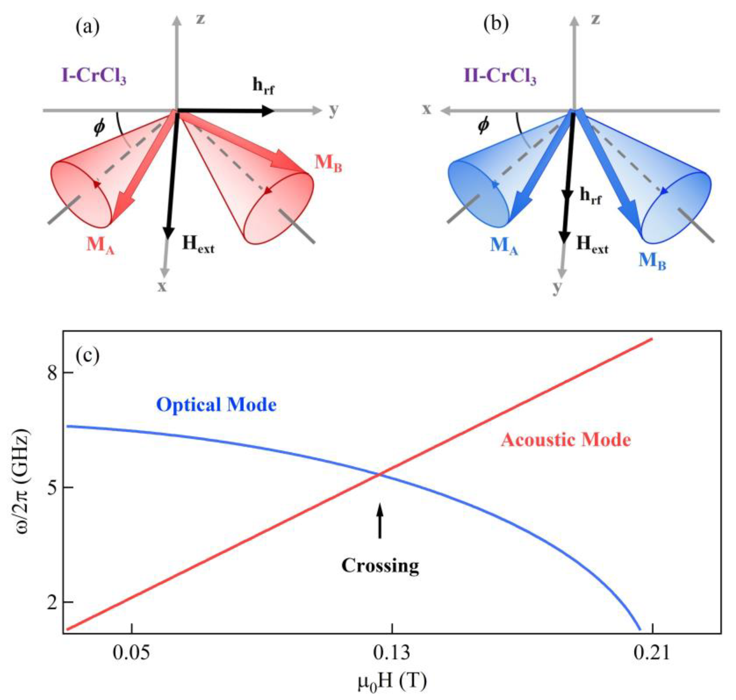
where the parameters μ0, γ, and α are the permeability in the vacuum, the gyromagnetic ratio, and the intrinsic Gilbert damping of CrCl3 crystal. Ms is the saturation magnetization of the magnetic moments M1 and M2 in sublattices. Heff1(2) = Hext + h + (HE/Ms)M2(1) − (M2(1) · z)z is the effective magnetic field acting on the magnetization in CrCl3 samples, where HE is the interlayer exchange field and z is the unit vector perpendicular to the sample plane. In the sample plane, we denote the direction of the driven microwave magnetic field he−iωt as y axis, where ω/2π is the frequency of the magnetic field, and Hext field applied on I-CrCl3 and II-CrCl3 samples are along the x axis and y axis, respectively, as shown in Figure 2a,b. We assume that M1 and M2 are initially antiparallel arranged on the axis perpendicular to Hext field, and they will rotate an angle ϕ as Hext field increasing. Here, the angle ϕ satisfies sinϕ = H/HE. By decoupling Equation (1) in two configurations (see the Appendix A) respectively, the LLG equation of I-CrCl3 can be simplified as:
( ω 2 ω r I 2 + i α ω ω s I ) m I + 2 ω m ( 2 ω e sin 2 ϕ + i α ω ) h = 0 ,
and the magnetization dynamic in II-CrCl3 crystal is described by:
( ω 2 ω r I I 2 + i α ω ω s I I ) m I I + 2 ω m cos 2 ϕ ( ω m + i α ω ) h = 0 ,
where the parameters ωsI = 2ωe(1 + sin2ϕ) + ωm and ωsII = 2ωecos2ϕ + ωm. Here, ωrI = sinϕ[2ωe(2ωe + ωm)]1/2 and ωrII = cosϕ(2ωeωm)1/2 describe the antiferromagnetic resonance frequencies of I-CrCl3 sample and II-CrCl3 sample, respectively, where ωm = μ0γMs and ωe = μ0γHE. The schematic diagrams of the precession orbits of the two sublattice magnetizations in the I-CrCl3 sample and the II-CrCl3 sample are shown in Figure 2a,b, respectively. The gray dash lines are the directions of the effective magnetic fields in the two sublattice. The antiferromagnetic magnon mode excited in the I-CrCl3 sample is the acoustic mode, M1 and M2 precess around the equilibrium position in right-handed with in-phase. In the II-CrCl3 sample, the precession of magnetization M1 and M2 have the same chirality as in the I-CrCl3 sample but display a π phase difference between, therefore the optical mode of antiferromagnetic resonance is excited. Figure 2c shows the theoretical ω-H dispersion of acoustic mode (red curve) and optical mode (blue curve), and the curves are calculated by ωrI and ωrII using the parameters of μ0HE = 0.105 T and μ0Ms = 0.27 T, which are determined by the experiment measurement at 4 K. When the magnons are not interact with each other, the acoustic mode excited in the I-CrCl3 sample and the optical mode excited in the II-CrCl3 sample are crossing.

3.2. Circuit Equation of the Microstrip Line

In general, a microwave cavity can be modeled as an artificial circuit that satisfies the LCR circuit equation [21,37]. Ignoring the capacitance term, the circuit equation of the microstrip line without charge accumulation is written by Kirchhoff’s equation as:
V = R j ( t ) + L d j ( t ) d t ,
where R and L are the resistance and inductance. j(t) = je−iωt represents the microwave current through the microstrip line, and β = R/ωL is denoted as the damping of the microstrip line.

3.3. Photon-Mediated Distant Magnon-Magnon Coupling Equation

In our settings, the optical mode and acoustic mode are separately excited in two distant CrCl3 crystals. By exchanging the microwave photons on the microstrip line, the excited distant magnons can interact with each other. Therefore, the coupling of magnon and microstrip line is the precondition of photon-mediated distant magnon-magnon coupling. We used the Faraday induction and Ampère’s law to link the coupling between magnon and microstrip line in theory [45]. The microwave magnetic field generated by the microwave current through the microstrip line is determined by the Ampère’s law h = −KmI(II)j, and the additional voltage of the artificial circuit induced from the precession of magnetization in I(II)-CrCl3 sample satisfies the Faraday induction VI(II) = KsI(II)LdmsI(II)/dt, where KmI(II) and KsI(II) are the coupling parameters. Connecting Equations (2)–(4) by the Faraday induction and Ampère’s law, the coupling equation of the hybrid system can be written as the following matrix:
( ω 2 ω r I 2 + i α ω ω s I 0 2 ω m sin 2 ϕ ( 2 ω e + ω m + i α ω ) 0 ω 2 ω r I I 2 + i α ω ω s I I 2 ω m cos 2 ϕ ( ω m + i α ω ) e i ϕ K I 2 K I I 2 1 + i β ) ( m I m I I h ) = ( 0 0 h 0 ) ,
where KI(II) = (KmI(II)KsI(II))1/2 is defined as the coupling constant between I(II)-CrCl3 sample and microstrip line. Here, the phase term e in the coupling equation is determined by the distance d of two samples with φ = ωd/c, where c = 3 × 10⁸ m/s is the velocity of electromagnetic waves in the vacuum. The parameter h0 is the input microwave magnetic field that driving the coupling systems.

4. Calculating Results and Discussion

Utilizing the microwave input-output formalism [24], the transmission spectrum of the coupling system is proportional to the ratio of the output microwave magnetic field and the input microwave magnetic field, and the formula can express as:
S 21 h h 0 = ( ω 2 ω r I 2 + i α ω ω s I ) ( ω 2 ω r I I 2 + i α ω ω s I I ) | 3 × 3 | ,
Here, |3 × 3| is the determinant of the matrix in Equation (5). The magnetizations in CrCl3 crystals are ferromagnetic coupling in the intralayer and antiferromagnetic coupling in the interlayer; and the Gilbert damping parameter are represented by a |2 × 2| matrix [50]. Here, to simplify, we consider the Gilbert damping parameter as a constant and take the value as α = 0.02. In the following discussions, the tiny damping of the microstrip line β = 0.001 and the coupling constants KI = KII = 0.3 are utilized to calculate the microwave transmission of the coupling system.
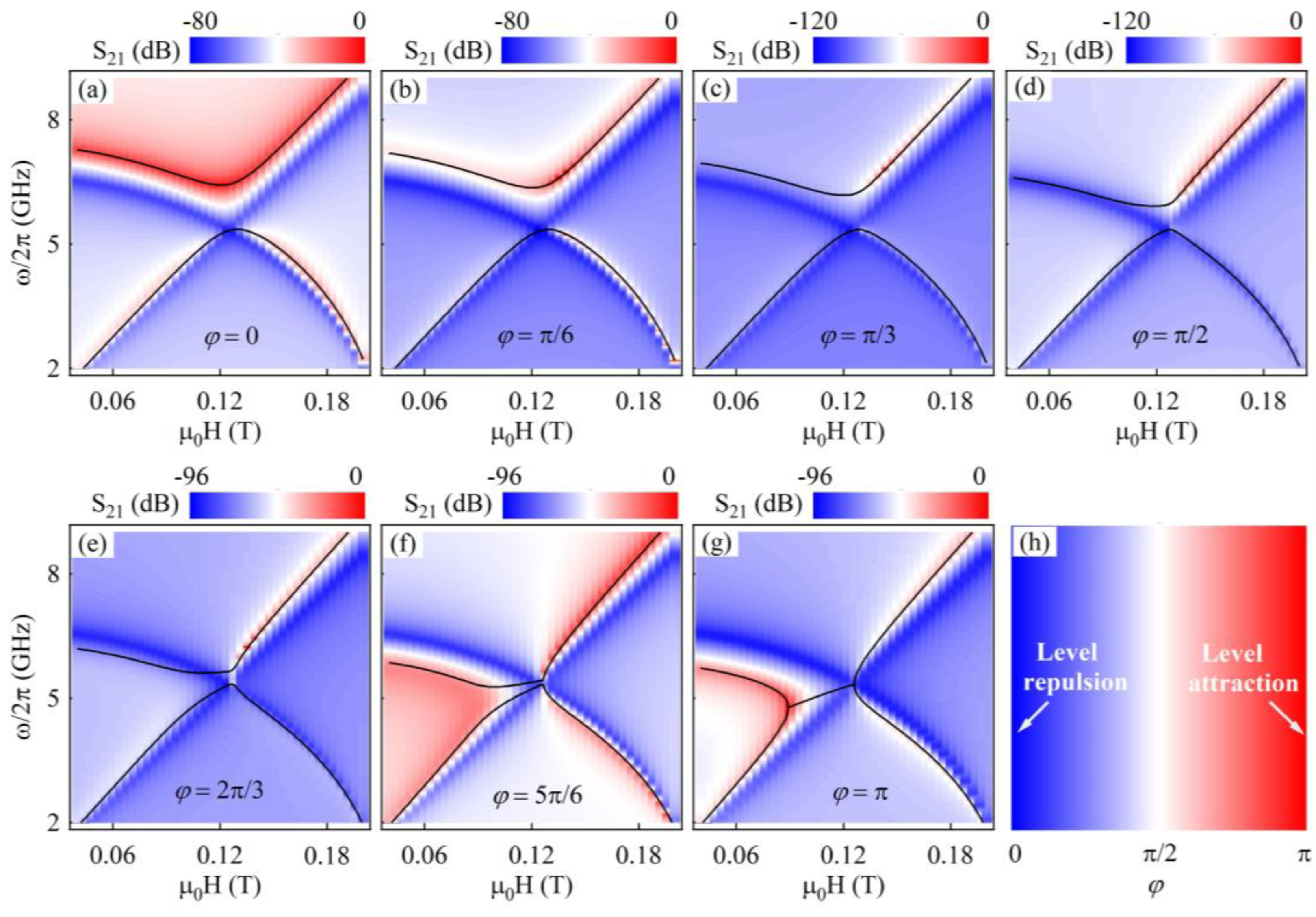
Figure 3a–g, calculated by Equation (6), are the transmission spectra mappings as a function of frequency and external magnetic field when the phase difference φ = 0, π/6, π/3, π/2, 2π/3, 5π/6 and π respectively. The resonant modes in blue color represent the uncoupled optical mode and acoustic mode, and the red modes are the coupled mode when the optical mode interact with the acoustic mode. The gray dash lines are the ω-H dispersion of the uncoupled optical mode and acoustic mode. The black solid curves in Figure 3a–g are the ω-H dispersion of the coupling modes, which are obtained by solving Equation (5). When the microwave magnetic field interacting with the CrCl3 crystals has no phase difference (φ = 0), namely the samples are space overlapping, the calculated ω-H dispersion of the coupling modes in Figure 3a opens a gap at the optical mode and acoustic mode crossing point and shows a level repulsion feature. In the region far away from the optical mode and acoustic mode crossing point, although the two modes still interact with each other, the ω-H dispersion of the two modes is similar with that of each mode when it is uncoupled. We can find that the oscillator strength of the upper coupling mode (the bright mode) is larger than the lower coupling mode (the dark mode). The level repulsion coupling features can also be observed when the distance between the spacial separated samples satisfies the relation of d = nλ, where λ is the microwave wavelength and n is an integer. The increase in the distance of the samples induces a phase difference φ of the exciting microwave magnetic field. Figure 3b shows the transmission spectra mappings of the hybrid system when the phase difference is equal to π/6. In this condition, though the oscillator strength of the left part of the upper coupling mode is weaker, the coupling mode of the upper branch is still brighter than that of the lower branch. The characteristic of the ω-H dispersion of the coupling modes is consistent with φ = 0, but the open gap at the optical mode and acoustic mode crossing point becomes smaller in this condition. As the phase difference increase, the open gap of the coupling ω-H dispersion continues to decrease, as shown in Figure 3c when φ = π/3. Figure 3d shows the transmission spectra mapping of the hybridized system with φ = π/2. In this condition, the intensity of the optical mode branch in both the upper and lower coupling modes is very weak and cannot even be observed, but the anticrossing feature of the acoustic mode branch indicates the coupling occurs in this hybrid system. As the phase difference φ continues to increase, the coupling modes show some different features. The oscillator strength of the optical mode reappears, and the upper branch and the lower branch of the coupling modes tend to attract with each other, as shown in Figure 3e,f when φ = 2π/3 and 5π/6. Next, we set the phase parameter to be φ = π, and the transmission spectra mapping of the hybrid system is shown in Figure 3g. In this case, the magnon dynamics of optical mode and acoustic mode impede each other due to the opposite phase leading a dissipative coupling. The ω-H dispersion of the coupling modes for this phase parameter set shows level attraction, and the tranmissiton intensity of the right coupling mode is much brighter than the left one. The level attraction of the dissipative coupling modes occurs by adjusting the distance of the samples to be d = nλ/2. In the above analyses, it can be found that the coupling modes change between level repulsion and level attraction when the phase difference is between 0 and π. The dependence of the coupling modes’ dispersion on the phase difference is shown in Figure 3h. The optimal values of the phase difference for the level repulsion and the level attraction are 0 and π, respectively.

5. Experimental Verification

In the experimental measurement, we put the experimental setup in Figure 1 into a physical property measurement system (PPMS) and set the measurement temperature at 4 K, as shown in Figure 4a. A vector network analyzer (VNA) with a driving power of −10 dBm connects to the two ports of the microstrip line using the coaxial lines to measure the microwave transmission spectra of the hybrid system by fixing the external magnetic field and sweeping microwave frequency. The center distance between two CrCl3 crystals on the microstrip line is set about d = 1.2 cm.
The measured microwave transmission spectra of the hybrid systems as a function of the normalized intensity and microwave frequency at the different fixed external magnetic fields are shown in Figure 4b. Although the ratio of signal to noise for the measurement result is low, the resonance magnon mode can be distinguished. As the external magnetic field increases, a magnon mode moves from low frequency to high frequency. The transmission spectrum highlighted in red color shows the resonance mode splits at μ0H = 0.136 T, which indicates the interaction of the magnon mode. Figure 4c shows the microwave transmission spectra mapping of the hybrid system. The frequency of the measured magnon mode is proportional to the applied external magnetic field, which is similar to the acoustic mode of CrCl3 crystal and determined as the acoustic mode branch of the coupling mode. As a result of the phase difference of the driving microwave magnetic field induced by the distance between the samples, the transmission intensity of the optical mode branch in the coupling modes is much weaker than the acoustic mode branch. However, the breaking of the acoustic mode branch in the coupling modes indicates the coupling occurs between the optical mode and the acoustic mode. We fit parameters of μ0HE = 0.112 T and μ0Ms = 0.316 T for CrCl3 crystals at 4 K and the coupling constants of KI = 0.21 and KII = 0.18. The distance between two samples produces the phase difference φ = 0.47π at the crossing frequency of ω/2π = 5.9168 GHz of the uncoupled optical mode and acoustic mode. The theoretical transmission spectra mapping calculated by Equation (6) using these fitting parameters is shown in Figure 4d. It exhibits the same breaking feature of the acoustic mode branch with the experimental measurement results. The ω-H dispersions showed by black curves in Figure 4c,d are calculated by solving Equation (5).

6. Conclusions

In conclusion, we demonstrate a method for realizing the distant magnon-magnon coupling mediated by the nonresonant microwave photon. The antiferromagnet CrCl3 crystals and the microstrip lines are taken as the research objects, and we theoretically and experimentally investigate the hybrid system. We establish a coupling model based on the LLG equations for antiferromagnetic resonance and Kirchhoff’s equation for the microstrip line to analyze the coupling system. The calculated microwave transmission spectra mapping of the coupling modes shows an anticrossing feature indicating the coupling between the optical mode and acoustic mode. By adjusting the samples distance to change their phase difference, we also predict that the level repulsion and level attraction of the coupling modes can be controlled. Furthermore, we verify the hybrid system in the experiment and observe that the dispersion of coupling modes has the same breaking feature with theoretical predictions. Our research on the distant magnon-magnon coupling might help control and utilize the light-mater interaction and design spintronics devices.

Author Contributions

Conceptualization, Q.Z. and L.B.; methodology, Q.Z. and L.B.; software, Q.Z. and Y.S.; formal analysis, Q.Z. and Y.S.; investigation, Q.Z. and J.X.; resources, Q.Z., J.X. and L.B.; data curation, Q.Z., Y.S. and L.B.; writing—original draft preparation, Q.Z.; writing—review and editing, Q.Z., Y.S., J.X. and L.B.; supervision, L.B.; project administration, L.B.; funding acquisition, L.B. All authors have read and agreed to the published version of the manuscript.

Funding

This work is supported by the National Natural Science Foundation of China (NSFC Grant No. 12274260), and the Youth Interdisciplinary Science and Innovative Research Groups of Shandong University.

Institutional Review Board Statement

Not applicable.

Informed Consent Statement

Not applicable.

Data Availability Statement

Not applicable.

Acknowledgments

Authors would like to thank the National Natural Science Foundation of China (NSFC Grant No. 12274260), and the Youth Interdisciplinary Science and Innovative Research Groups of Shandong University for supporting this work.

Conflicts of Interest

The authors declare no conflict of interest.

Appendix A. Decoupling the LLG Equations

The two sublattice magnetic moments M1 and M2 can be expanded as M1(2) = Meq1(2) + m1(2)e−iωt, where Meq1(2) determined by the effective magnetic field is the magnetization in equilibrium position, as shown by the gray dash lines in Figure 2a,d. Substituting M1 and M2 in Equations (1), it can be rewritten as
i ω m 1 = μ 0 γ M 1 e q × ( H e q M s m 1 + H E M s m 2 + ( m 1 z ) z h ) i α ω M s M 1 e q × m 1 ,
i ω m 2 = μ 0 γ M 2 e q × ( H e q M s m 2 + H E M s m 1 + ( m 2 z ) z h ) i α ω M s M 2 e q × m 2 ,
where Heq is a positive number and has a relation of HextMeq1HE/Ms = Meq2Heq/Ms. Here, Heq = |HextMeq1HE/Ms| = HE. We make the operator C2 acts on both side of Equation (1b) and utilize the relations mI = m1C2m2 and mII = m1 + C2m2 where C2 denotes the vector rotate around the external magnetic field by 180°, and Equations (A1a) and (A1b) can be decoupled as
i ω m I = μ 0 γ M 1 e q × H e f f I i α ω M s M 1 e q × m I ,
i ω m I I = μ 0 γ M 1 e q × H e f f I I i α ω M s M 1 e q × m I I
where HeffI = (HE/Ms)(mIC2mI) + (mI · z)zhI and HeffII = (HE/Ms)(mII + C2mII) + (mII · z)zhII are the effective magnetic fields. Solving the Equations (A2a) and (A2b) in the coordinate system shown in Figure 2a,b, respectively, we can deduce the Equations (2) and (3).

References

  1. Amsüss, R.; Koller, C.; Nöbauer, T.; Putz, S.; Rotter, S.; Sandner, K.; Schneider, S.; Schramböck, M.; Steinhauser, G.; Ritsch, H.; et al. Cavity QED with magnetically coupled collective spin states. Phys. Rev. Lett. 2011, 107, 060502. [Google Scholar] [CrossRef] [PubMed] [Green Version]
  2. Singh, M.R.; Schindel, D.G.; Hatef, A. Dipole-dipole interaction in a quantum dot and metallic nanorod hybrid system. Appl. Phys. Lett. 2011, 99, 181106. [Google Scholar] [CrossRef]
  3. Kurizki, G.; Bertet, P.; Kubo, Y.; Mølmer, K.; Petrosyan, D.; Rabl, P.; Schmiedmayer, J. Quantum technologies with hybrid systems. Proc. Natl. Acad. Sci. USA 2015, 112, 3866–3873. [Google Scholar] [CrossRef] [Green Version]
  4. Wallraff, A.; Schuster, D.I.; Blais, L.; Frunzio, L.; Huang, R.S.; Majer, J.; Kumar, S.; Girvin, S.M.; Schoelkopf, R.J. Strong coupling of a single photon to a superconducting qubit using circuit quantum electrodynamics. Nature 2004, 431, 162–167. [Google Scholar] [CrossRef] [Green Version]
  5. Holmes, R.J.; Forrest, R. Strong exciton-photon coupling in organic materials. Org. Electron. 2007, 8, 77–93. [Google Scholar] [CrossRef]
  6. Reithmaier, J.P. Strong exciton-photon coupling in semiconductor quantum dot systems. Semicond. Sci. Tech. 2008, 23, 123001. [Google Scholar] [CrossRef]
  7. Delbecq, M.R.; Bruhat, L.E.; Viennot, J.J.; Datta, S.; Cottetl, A.; Kontos, T. Photon-mediated interaction between distant quantum dot circuits. Nat. Commun. 2013, 4, 1400. [Google Scholar] [CrossRef] [Green Version]
  8. Yadav, A.; Kumari, R.; Varshney, S.K.; Lahiri, B. Tunable phonon-plasmon hybridization in α-MoO3-graphene based van der Waals heterostructures. Opt. Express 2021, 29, 33171–33183. [Google Scholar] [CrossRef]
  9. Wolf, S.A.; Awschalom, D.D.; Buhrman, R.A.; Daughton, J.M.; Molnar, S.V.; Roukes, M.L.; Chtchelkanova, A.Y.; Treger, D.M. Spintronics: A Spin-based electronics vision for the future. Science 2001, 294, 1488–1495. [Google Scholar] [CrossRef] [PubMed] [Green Version]
  10. Takahashi, S.; Maekawa, S. Spin current, spin accumulation and spin Hall effect. Sci. Technol. Adv. Mater. 2008, 9, 014105. [Google Scholar] [CrossRef]
  11. Kent, A.; Worledge, D. A new spin on magnetic memories. Nat. Nanotechnol. 2015, 10, 187–191. [Google Scholar] [CrossRef] [PubMed]
  12. Wang, X.S.; Zhang, H.W.; Wang, X.R. Topological magnonics: A paradigm for spin-wave manipulation and device design. Phys. Rev. Appl. 2018, 9, 024029. [Google Scholar] [CrossRef]
  13. Coronado, E. Molecular magnetism: From chemical design to spin control in molecules, materials and devices. Nat. Rev. Mater. 2020, 5, 87–104. [Google Scholar] [CrossRef]
  14. Hirohata, A.; Yamada, K.; Nakatani, Y.; Prejbeanu, I.L.; Diény, B.; Pirro, P.; Hillebrands, B. Review on spintronics: Principles and device applications. J. Magn. Magn. Mater. 2020, 509, 166711. [Google Scholar] [CrossRef]
  15. Dicke, R.H. Coherence in Spontaneous Radiation Processes. Phys. Rev. 1954, 93, 99. [Google Scholar] [CrossRef] [Green Version]
  16. Tabuchi, Y.; Ishino, S.; Ishikawa, T.; Yamazaki, R.; Usami, K.; Nakamura, Y. Hybridizing ferromagnetic magnons and microwave photons in the quantum limit. Phys. Rev. Lett. 2014, 113, 083603. [Google Scholar] [CrossRef] [Green Version]
  17. Odintsov, S.A.; Beginin, E.N.; Sheshukova, S.E.; Sadovnikov, A.V. Reconfigurable lateral spin-wave transport in a ring magnonic microwaveguide. JETP Lett. 2019, 110, 430–435. [Google Scholar] [CrossRef]
  18. Yuan, H.Y.; Cao, Y.; Kamra, A.; Duine, R.A.; Yan, P. Quantum magnonics: When magnon spintronics meets quantum information science. Phys. Rep. 2022, 965, 1–74. [Google Scholar] [CrossRef]
  19. Sadovnikov, S.A.; Bublikov, K.V.; Beginin, E.N.; Sheshukova, S.E.; Sharaevskii, Y.P.; Nikitov, S.A. Nonreciprocal propagation of hybrid electromagnetic waves in a layered ferrite-ferroelectric structure with a finite width. JETP Lett. 2015, 102, 142–147. [Google Scholar] [CrossRef]
  20. Klingler, S.; Amin, V.; Geprägs, S.; Ganzhorn, K.; Hannes, M.; Althammer, M.; Huebl, H.; Gross, R.; McMichael, R.D.; Stiles, M.D.; et al. Spin-torque excitation of perpendicular standing spin waves in coupled YIG/Co heterostructures. Phy. Rev. Lett. 2018, 120, 127201. [Google Scholar] [CrossRef]
  21. Soykal, Ö.O.; Flatté, M.E. Strong field Interactions between a nanomagnet and a photonic cavity. Phys. Rev. Lett. 2010, 104, 077202. [Google Scholar] [CrossRef] [PubMed] [Green Version]
  22. Huebl, H.; Zollitsch, C.W.; Lotze, J.; Hocke, F.; Greifenstein, M.; Marx, A.; Gross, R.; Goennenwein, S.T.B. High cooperativity in coupled microwave resonator ferrimagnetic insulator hybrids. Phys. Rev. Lett. 2013, 111, 127003. [Google Scholar] [CrossRef] [PubMed] [Green Version]
  23. Zhang, X.; Zou, C.L.; Jiang, L.; Tang, H.X. Strongly coupled magnons and cavity microwave photons. Phys. Rev. Lett. 2014, 113, 156401. [Google Scholar] [CrossRef] [PubMed] [Green Version]
  24. Grigoryan, V.L.; Shen, K.; Xia, K. Synchronized spin-photon coupling in a microwave cavity. Phys. Rev. B 2018, 98, 024406. [Google Scholar] [CrossRef] [Green Version]
  25. Hisatomi, R.; Osada, A.; Tabuchi, Y.; Ishikawa, T.; Noguchi, A.; Yamazaki, R.; Usami, K.; Nakamura, Y. Bidirectional conversion between microwave and light via ferromagnetic magnons. Phys. Rev. B 2016, 93, 174427. [Google Scholar] [CrossRef] [Green Version]
  26. Zhang, D.; Song, W.; Chai, G. Spin-wave magnon-polaritons in a split-ring resonator/single-crystalline YIG system. J. Phys. D Appl. Phys. 2017, 50, 205003. [Google Scholar] [CrossRef]
  27. Harder, M.; Yang, Y.; Yao, B.M.; Yu, C.H.; Rao, J.W.; Gui, R.L.; Stamps, R.L.; Hu, C.M. Level attraction due to dissipative magnon-photon coupling. Phys. Rev. Lett. 2018, 121, 137203. [Google Scholar] [CrossRef] [Green Version]
  28. Xiao, Y.; Yan, X.H.; Zhang, Y. Magnon dark mode of an antiferromagnetic insulator in a microwave cavity. Phys. Rev. B 2019, 99, 094407. [Google Scholar] [CrossRef]
  29. Bialek, M.; Zhang, J.; Yu, H.; Ansermet, J.P. Strong coupling of antiferromagnetic resonance with subterahertz cavity fields. Phys. Rev. Appl. 2020, 15, 044018. [Google Scholar] [CrossRef]
  30. Zhang, Q.; Sun, Y.; Lu, Z.; Guo, J.; Xue, J.; Chen, Y.; Tian, Y.; Yan, S.; Bai, L. Zero-field magnon-photon coupling in antiferromagnet CrCl3. Appl. Phys. Lett. 2021, 119, 102402. [Google Scholar] [CrossRef]
  31. Zhang, Q.; Xue, J.; Sun, Y.; Guo, J.; Chen, Y.; Tian, Y.; Yan, S.; Bai, L. Coupling of microwave photons to optical and acoustic magnon modes in the layered antiferromagnetic insulator CrCl3. Phys. Rev. B 2021, 104, 094303. [Google Scholar] [CrossRef]
  32. Harder, M.; Yao, B.M.; Gui, Y.S.; Hu, C.M. Coherent and dissipative cavity magnonics. J. Appl. Phys. 2021, 129, 201101. [Google Scholar] [CrossRef]
  33. Sohail, A.; Ahmed, R.; Zainab, R.; Yu, C. Enhanced entanglement and quantum steering of directly and indirectly coupled modes in a magnomechanical system. Phys. Scr. 2022, 97, 075102. [Google Scholar] [CrossRef]
  34. Tabuchi, Y.; Ishino, S.; Nogushi, A.; Ishikawa, T.; Yamazaki, R.; Usami, K.; Nakamura, Y. Coherent coupling between a ferromagnetic magnon and a superconducting qubit. Science 2015, 349, 405–408. [Google Scholar] [CrossRef] [PubMed] [Green Version]
  35. Zhang, X.; Zou, C.L.; Jiang, L.; Tang, H.X. Cavity magnomechanics. Sci. Adv. 2016, 2, e1501286. [Google Scholar] [CrossRef] [PubMed] [Green Version]
  36. Li, J.; Zhu, S.Y.; Agarwal, G.S. Magnon-photon-phonon entanglement in cavity magnomechanics. Phys. Rev. Lett. 2018, 121, 203601. [Google Scholar] [CrossRef] [Green Version]
  37. Zhu, N.; Han, X.; Zou, C.L.; Xu, M.; Tang, H.X. Magnon-photon strong coupling for tunable microwave circulators. Phys. Rev. A 2019, 101, 043842. [Google Scholar] [CrossRef]
  38. Yu, W.; Yu, T.; Bauer, G.E.W. Circulating cavity magnon polaritons. Phys. Rev. B 2020, 102, 064416. [Google Scholar] [CrossRef]
  39. Rao, J.W.; Kaur, S.; Yao, B.M.; Edwards, E.R.J.; Zhao, Y.T.; Fan, X.; Xue, D.; Silva, T.J.; Gui, Y.S.; Hu, C.M. Analogue of dynamic Hall effect in cavity magnon polariton system and coherently controlled logic device. Nat. Commun. 2019, 10, 2934. [Google Scholar] [CrossRef] [Green Version]
  40. Lambert, N.J.; Haigh, J.A.; Langenfeld, S.; Doherty, A.C.; Ferguson, A.J. Cavity-mediated coherent coupling of magnetic moments. Phys. Rev. A 2016, 93, 021803. [Google Scholar] [CrossRef]
  41. Bai, L.; Harder, M.; Hyde, P.; Zhang, Z.; Hu, C.M. Cavity mediated manipulation of distant spin currents using a cavity-magnon-polariton. Phys. Rev. Lett. 2017, 118, 217201. [Google Scholar] [CrossRef] [PubMed] [Green Version]
  42. Johansen, Ö.; Brataas, A. Nonlocal coupling between antiferromagnets and ferromagnets in cavities. Phys. Rev. Lett. 2018, 121, 087204. [Google Scholar] [CrossRef] [PubMed] [Green Version]
  43. Rameshti, B.Z.; Bauer, G.E.W. Indirect coupling of magnons by cavity photons. Phys. Rev. B 2018, 97, 014419. [Google Scholar] [CrossRef] [Green Version]
  44. Xu, P.C.; Rao, J.W.; Gui, Y.S.; Jin, X.; Hu, C.M. Cavity-mediated dissipative coupling of distant magnetic moments: Theory and experiment. Phys. Rev. B 2019, 100, 094415. [Google Scholar] [CrossRef] [Green Version]
  45. Grigoryan, V.L.; Xia, K. Cavity-mediated dissipative spin-spin coupling. Phys. Rev. B 2019, 100, 014415. [Google Scholar] [CrossRef] [Green Version]
  46. Nair, J.M.P.; Mukhopadhyay, D.; Agarwal, G.S. Cavity mediated level attraction and repulsion between magnons. Phys. Rev. B 2022, 105, 214418. [Google Scholar] [CrossRef]
  47. Ren, Y.; Xie, J.; Li, X.; Ma, S.; Li, F. Long-range generation of a magnon-magnon entangled state. Phys. Rev. B 2022, 105, 094422. [Google Scholar] [CrossRef]
  48. MacNeill, D.; Hou, J.T.D.; Klein, R.; Zhang, P.; Herrero, P.J.; Liu, L. Gigahertz frequency antiferromagnetic resonance and strong magnon-magnon coupling in the layered crystal CrCl3. Phys. Rev. Lett. 2019, 123, 047204. [Google Scholar] [CrossRef] [Green Version]
  49. Silva, T.J.; Lee, C.S.; Crawford, T.M.; Rogers, C.T. Inductive measurement of ultrafast magnetization dynamics in thin-film Permalloy. J. Appl. Phys. 1999, 85, 7849–7862. [Google Scholar] [CrossRef] [Green Version]
  50. Mi, X.; Wang, L.; Zhang, Q.; Sun, Y.; Tian, Y.; Yan, S.; Bai, L. Gilbert damping in the layered antiferromagnet CrCl3. Chin. Phys. B 2022, 31, 027505. [Google Scholar] [CrossRef]
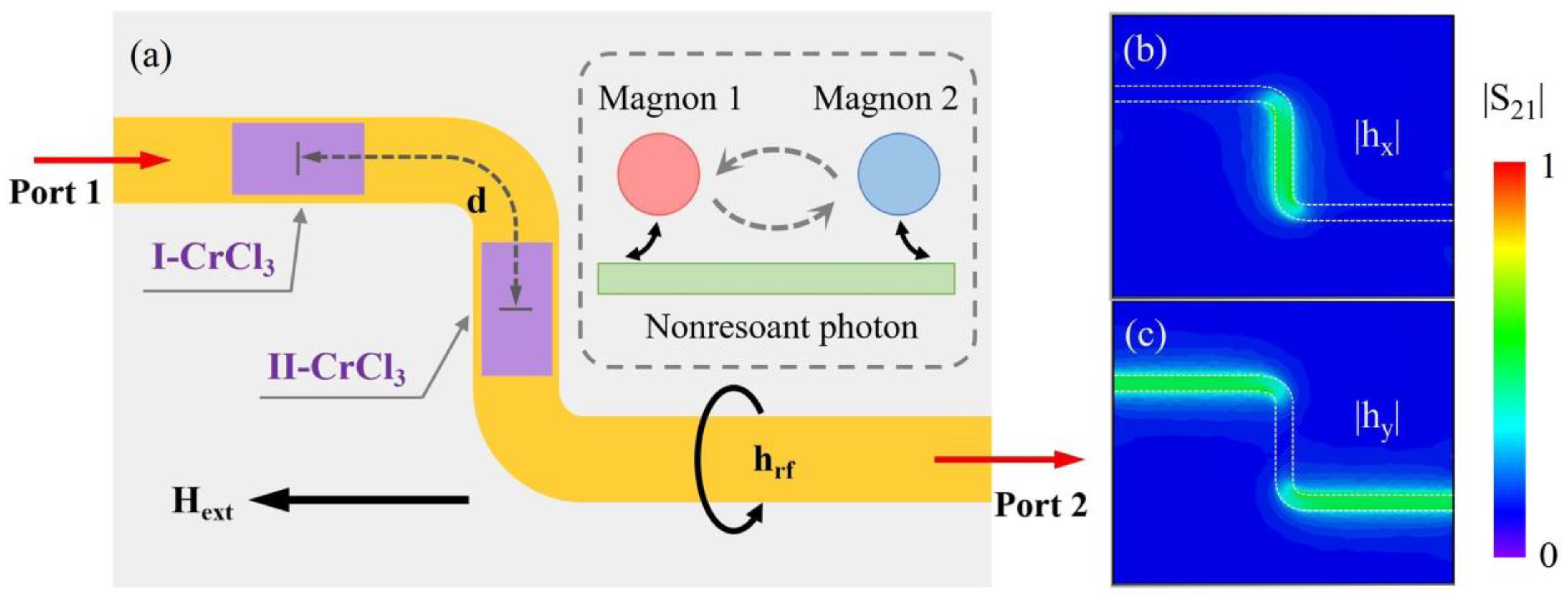
Figure 1. (a) The schematic diagram of the nonresonant photon mediated distant magnon-magnon coupling. The inset illustrates the coupling principle of the hybrid system consisting of three physical subsystems. The normalized amplitude distributions on the surface of the microstrip line for the microwave magnetic field components of |hx| (b) and |hy| (c).
Symmetry 15 00518 g001
Figure 2. Schematic diagrams the precession orbits of the two sublattice magnetizations for the acoustic mode (red) in I-CrCl3 sample (a) and the optical mode (blue) in II-CrCl3 sample (b). (c) The theoretical calculated results of the ω-H dispersion for the uncoupled optical mode and acoustic mode in CrCl3 crystals.
Symmetry 15 00518 g002
Figure 3. The calculated transmission spectra mappings of the hybrid system as a function of frequency and external magnetic field with the phase parameters set at φ = 0 (a), π/6 (b), π/3 (c), π/2 (d), 2π/3 (e), 5π/6 (f) and π (g). The transmission spectra are calculated by Equation (6), and the ω-H dispersions (black lines) in the figures are obtained by solving Equation (5), and the gray dash lines represent the uncoupled optical mode and acoustic mode. (h) The variation of the coupling dispersion from level repulsion to level attraction with phase difference φ from 0 to π.
Symmetry 15 00518 g003
Figure 4. (a) The experimental setup for measuring the two spacial separated CrCl3 crystals with the centre distance of d = 1.2 cm. (b) the transmission spectra as function of the normalized intensity and frequency at different external magnetic field. (c) The experimental result of the transmission spectra mapping of two spacial separated CrCl3 crystals with the center distance of d = 1.2 cm. (d) The corresponding theoretical result calculated by Equation (6). ω-H dispersion plotted by black curves are calculated by solving Equation (5).
Symmetry 15 00518 g004
Disclaimer/Publisher’s Note: The statements, opinions and data contained in all publications are solely those of the individual author(s) and contributor(s) and not of MDPI and/or the editor(s). MDPI and/or the editor(s) disclaim responsibility for any injury to people or property resulting from any ideas, methods, instructions or products referred to in the content.