Correction: Ning et al. Deep Vision Servo Hand-Eye Coordination Planning Study for Sorting Robots. Symmetry 2022, 14, 152

 ,
, 1. Addition of Authors
- Author Contributions: Conceptualization, methodology, J.L., C.H., Y.Z., P.L.; software, T.N. and C.W.; formal analysis, Y.H. and Y.G.; resources, T.N., Y.J. and J.L.; writing—original draft preparation, T.N. and C.W.; writing—review and editing, T.N.; funding acquisition, T.N. and Y.H.
2. In Abstract and Keywords
- Abstract: Within the context of large-scale symmetry, a study on deep vision servo multi-vision tracking coordination planning for sorting robots was conducted according to the problems of low recognition sorting accuracy and efficiency in existing sorting robots. In this paper, a kinematic model of a mobile picking manipulator was built. Then, the kinematics design of the orwX, Y, Z three-dimensional space manipulator was carried out, and a method of deriving and calculating the base position coordinates through the target point coordinates, the current moving chassis center coordinates and the determined manipulator grasping attitude conditions was proposed, which realizes the adjustment of the position and attitude of the moving chassis as small as possible. The multi-vision tracking coordinated sorting accounts 79.8% of the whole cycle. The design of a picking robot proposed in this paper can greatly improve the coordination symmetry of logistic package target recognition, detection and picking.
- Keywords: picking manipulator; multi-vision tracking coordination; pattern recognition
3. In Section 1. Introduction, Paragraph 2, Table 1 and under Table 1.

| Methods | Characteristic |
|---|---|
| Greedy algorithm [3] | path is too long, too much time spent |
| Visual servo robot [4] | only meet medium and large parcels |
| Humanoid dual-arm robot [5] | experimental accuracy is insufficient, and Multi vision tracking coordination control is not fully realized |
| RealSense picking robot [6] | the experiment only achieved two-dimensional image pixel position |
| Multi vision tracking system based on RSRR300 [7] | the control study of Multi vision tracking coordination has not been conducted |
| Proposed method | lifting picking robot and “far and near” Multi vision tracking coordination control |
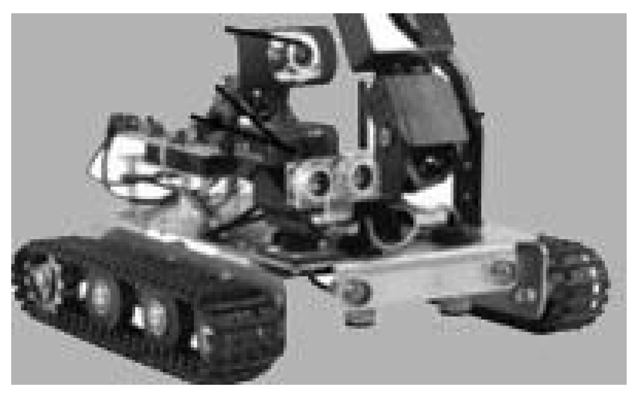
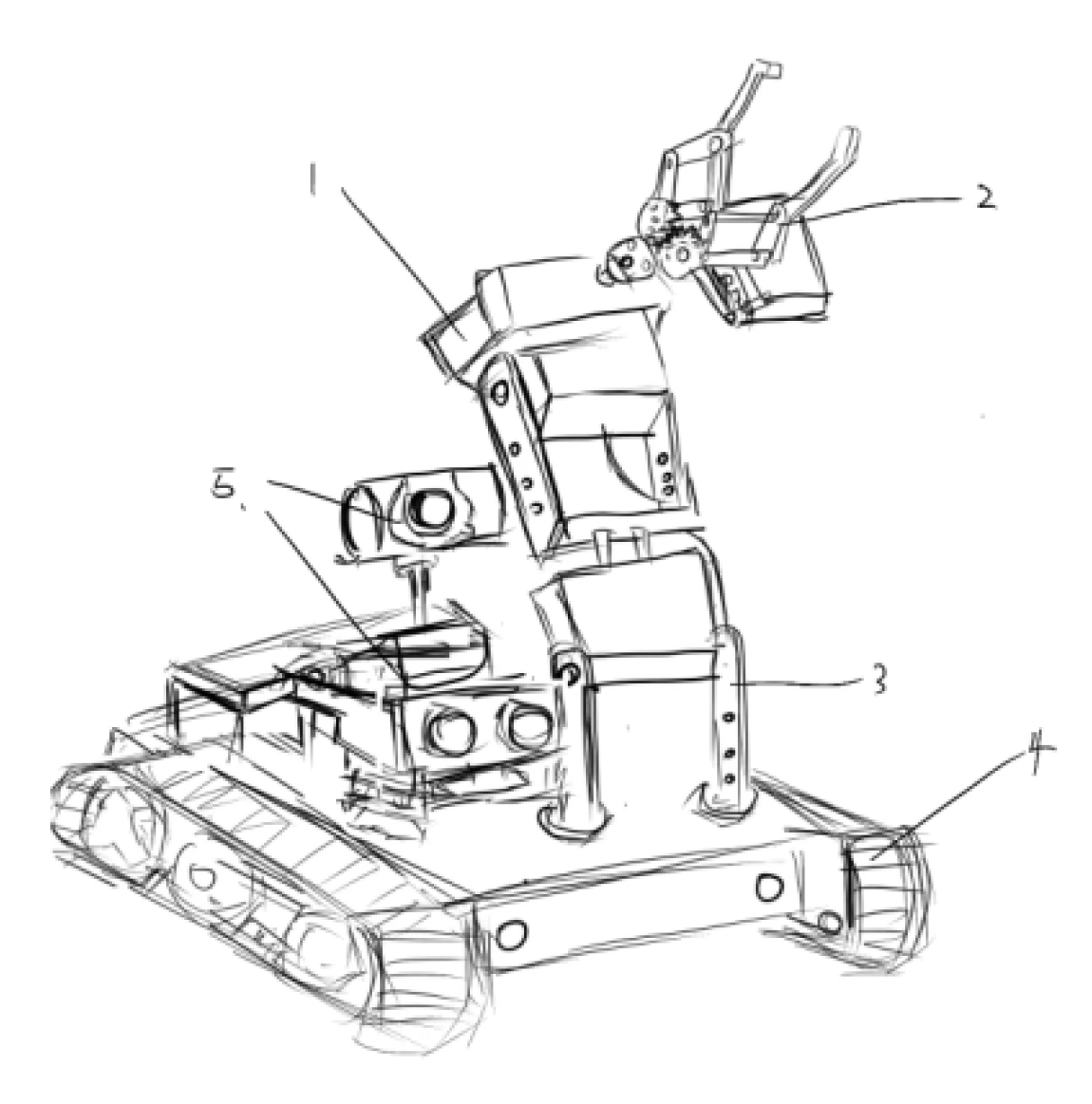
4. Section 2 Is Redescribed, and Figure 1 is Updated
- (1)
- A 3D rotating shaft mechanism driven by AC motor is designed to maximize the freedom of the picking space. At the same time, the stability of the chassis crawler is designed to overcome the imbalance caused by large packages.
- (2)
- Based on the three-dimensional joint manipulator, the retractable rotary structure of the grasping rotating platform is designed. The manipulator with a high degree of freedom is composed of a grasping device, a rotating mechanism and three claw end components. The positioning and picking of express packages are completed in the set height area, so as to reduce the complexity of grasping movement and shorten the movement cycle without rotation.
- (3)
- In this paper, a stereo vision recognition system combining binocular camera and monocular camera is designed. Referring to the same type of mechanical devices, the depth of field is set within the range of 120–1500 mm, and the field of view is set at 70 degrees in the vertical direction and 90 degrees in the horizontal direction, so as to ensure the accurate positioning of the three–eye camera combined in the near and far range.
5. Section 3.1 Is Corrected as Follows, and Section 3.1.1 Is Deleted
6. In Section 3.2
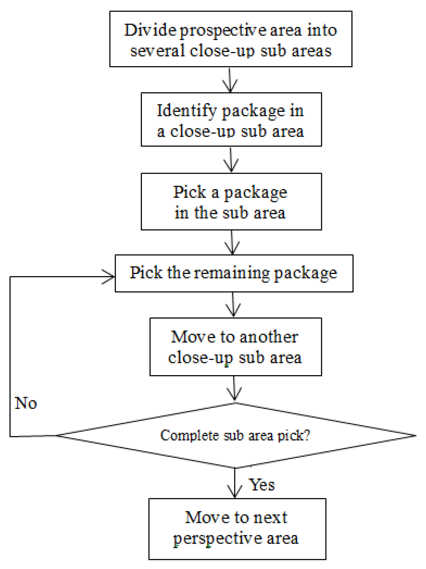
7. Section 4 Is Updated as Follow
- (1)
- The robot arm scans the package horizontally at a distance of 350–800 mm from the top of the package to obtain the long-range vertical height crest data of the package. The 800 mm detection area is 1126 mm × 810 mm, and the 350 mm detection area is 720 mm × 520 mm [12].
- (2)
- Close view position: After determining the subregion, the robot arm moves to the center of the targeted subregion, which is the best close view position at 200 mm from the subregion, and still uses the horizontal altitude as the ideal altitude. The vision sensor detection area is 288 mm × 208 mm [12].
- (3)
- Picking position: According to the coordinates of the targeted parcel, the robot arm reaches the picking position through altitude planning and picks the parcels up in a horizontal or upward or downward altitude.
8. Figure 3 Is Updated as Follow
9. In Section 5.2.1. Test Material
10. Section 7. Conclusions Is Corrected as Follows
11. In Reference Section
- 10.
- Jin, Y.; Gao, Y.; Liu, J.; Hu, C.; Zhou, Y.; Li, P. Hand-eye coordination planning with deep visual servo for harvesting robot. Trans. Chin. Soc. Agric. Mach. 2021, 52, 18–25, 42.
Reference
- Ning, T.; Wang, C.; Han, Y. Deep Vision Servo Hand-Eye Coordination Planning Study for Sorting Robots. Symmetry 2022, 14, 152. [Google Scholar] [CrossRef]
| Key Point | Coordinates Value/mm | Joint Parameters |
|---|---|---|
| Initial position P0 | (698, −57.3, 0) | (0 mm, 0°, 0°, 0°) |
| Prospective position P1 | (618.207, 339.391, 451.683) | (163 mm, 22.1°, 51.8°, −41.8°) |
| Picking position P2 | (648.107, 194.283, 468.602) | (163 mm, 31.8°, 13.9°, −25.6°) |
| Placing position P3 | (451.687, −342.238, 129.343) | (163 mm, −11.8°, 44.1°, −108.2°) |
Disclaimer/Publisher’s Note: The statements, opinions and data contained in all publications are solely those of the individual author(s) and contributor(s) and not of MDPI and/or the editor(s). MDPI and/or the editor(s) disclaim responsibility for any injury to people or property resulting from any ideas, methods, instructions or products referred to in the content. |
© 2022 by the authors. Licensee MDPI, Basel, Switzerland. This article is an open access article distributed under the terms and conditions of the Creative Commons Attribution (CC BY) license (https://creativecommons.org/licenses/by/4.0/).
Share and Cite
Ning, T.; Wang, C.; Han, Y.; Jin, Y.; Gao, Y.; Liu, J.; Hu, C.; Zhou, Y.; Li, P. Correction: Ning et al. Deep Vision Servo Hand-Eye Coordination Planning Study for Sorting Robots. Symmetry 2022, 14, 152. Symmetry 2023, 15, 82. https://doi.org/10.3390/sym15010082
Ning T, Wang C, Han Y, Jin Y, Gao Y, Liu J, Hu C, Zhou Y, Li P. Correction: Ning et al. Deep Vision Servo Hand-Eye Coordination Planning Study for Sorting Robots. Symmetry 2022, 14, 152. Symmetry. 2023; 15(1):82. https://doi.org/10.3390/sym15010082
Chicago/Turabian StyleNing, Tao, Chengguo Wang, Yumeng Han, Yuchen Jin, Yan Gao, Jizhen Liu, Chunhua Hu, Yangyang Zhou, and PinPin Li. 2023. "Correction: Ning et al. Deep Vision Servo Hand-Eye Coordination Planning Study for Sorting Robots. Symmetry 2022, 14, 152" Symmetry 15, no. 1: 82. https://doi.org/10.3390/sym15010082
APA StyleNing, T., Wang, C., Han, Y., Jin, Y., Gao, Y., Liu, J., Hu, C., Zhou, Y., & Li, P. (2023). Correction: Ning et al. Deep Vision Servo Hand-Eye Coordination Planning Study for Sorting Robots. Symmetry 2022, 14, 152. Symmetry, 15(1), 82. https://doi.org/10.3390/sym15010082