You are currently viewing a new version of our website. To view the old version click .
Symmetry
  • Article
  • Open Access

23 March 2021

Implementation and Evaluation of Physical, Hybrid, and Virtual Testbeds for Cybersecurity Analysis of Industrial Control Systems

,
,
,
and
1
School of Computing, Edinburgh Napier University, Edinburgh EH10 5DT, UK
2
School of Engineering and Built Environment, Edinburgh Napier University, Edinburgh EH10 5DT, UK
*
Author to whom correspondence should be addressed.
This article belongs to the Section Computer

Abstract

Industrial Control Systems are an essential part of our daily lives and can be found in industries such as oil, utilities, and manufacturing. Rapid growth in technology has introduced industrial components with network capabilities that allow them to communicate with traditional computer networks, thus increasing their exposure to cyber-attacks. Current research on Industrial Control Systems suffer from lack of technical information as these systems are part of critical infrastructures. To overcome this, researchers have employed different types of testbeds to develop their mechanisms of cyber-attack detection and prevention. This manuscript describes, implements, and evaluates physical, hybrid, and virtual application of a clean water supply system developed for cybersecurity research. The results show that physical testbeds allow an understanding of the behaviour and dynamics of control components like sensors and actuators, which might be affected by external influences such as noise, vibration, temperature, and non-ideal device behaviour. Although, hybrid testbeds reduce the cost of implementation, they ignore the physical dynamics of the system as explained above. Virtual testbeds are the cheapest option in comparison with physical and hybrid testbeds; however, they provide a limited view of the control system operation that could have negative consequences when developing a detection/prevention system.

1. Introduction

Industrial Control System (ICS) is a general term used to define the integration of hardware and software with network connectivity used to operate industrial processes [1]. ICS often includes Supervisory Control and Data Acquisition (SCADA) systems, Distributed Control Systems (DCS), and different control system configurations such as Programmable Logic Controllers (PLC). PLC can be found in industrial sectors and critical infrastructure such as oil, pharmaceutical, power plants, and water distribution systems. These industrial sectors contribute to the economy of a country and are an essential part of the daily services used by citizens. For instance, there are 13 critical national infrastructure sectors (such as: water, transport, chemical, space, food, defence, government and civil nuclear) identified in the UK, which are important for the operation of the country [2] and whose possible compromise might involve the loss of human lives. In the US, Homeland Security [3] defines 16 critical infrastructure sectors (such as: dams, emergency services, information technology, commercial infrastructure, critical manufacturing, and communications) as fundamental pillars for the operation of the country, whose damage might have devastating consequences on the public, economy, and environment. In general, the US and the UK focus on the same critical infrastructure and the difference is on the classification of such infrastructure.
Control system technology has grown in leaps and bounds over the past decades allowing to evolve from mechanical through electrical/electronic to microprocessor-based systems. This evolution has increased the connectivity of ICSs with corporate networks and the Internet. As a result, old industrial infrastructures with unpatched systems are exposed to skilled hackers that can easily take advantages of their online availability. For instance, in 2010 the Stuxnet worm demonstrated the vulnerabilities of ICSs and their potential threat when a malware destroyed a considerable amount of Iran’s nuclear centrifuges [4].
ICS have attracted the attention of cybercriminals because it is composed of old equipment with obsolete or no security measures. For example, a considerable number of computers involved in ICS operations still run on older operating systems, such as Windows XP or Windows 7, without the latest patches. According to the report published in [1] this is attributed to the uncertain results of applying security patches despite its security benefits. IT systems benefit from the flexibility that virtualization provides. It enables the latest security patches to be applied to a virtual copy of any computer before it is applied to productive systems. This allows evaluating the impact of security patches on the system and applications in case their normal operation is affected. In contrast, the cost of replicating an ICS is considerably high because it involves purchasing expensive control equipment and having physical space available. For example, industries such as oil, nuclear, and water cannot afford to implement a control process to test only for security patches. However, as demonstrated in this research, it is possible to downscale a model of an ICS on equipment that may be available in University laboratories. Throughout the investigation we compare the differences in implementations of physical and virtual control systems. Each of the approaches has its advantages and disadvantages as discussed throughout this paper.

1.1. Research Questions

The experiments conducted in this paper aim to describe the advantages and disadvantages of using physical, hybrid, or virtual testbeds for cybersecurity research on ICS. The research questions that will be answered in the course of this paper are as follows.
Research Question 1. How does a hybrid and virtual implementation of a clean water supply system differ during normal operation and under attack scenarios in comparison with the physical model of such a system?
Research Question 2. Can we rely on mechanism of anomaly detection on ICS which are developed and tested on virtual platforms?

1.2. Contribution

In this paper, a cybersecurity analysis of a physical, hybrid and virtual testbed that simulates a clean water supply system is discussed. A set of attacks against the working memory of the PLC is executed aiming to analyse the behaviour of such attacks on the implemented testbeds. The results show the strengths and weaknesses of each approach.

1.3. Organization of the Paper

This paper is organised as follows: In Section 2, we review related work with a focus on testbeds for ICS cybersecurity research. In Section 3, we describe the design and implementation of the three testbeds presented in this research. In Section 4 the testbeds are evaluated by highlighting their strengths and weaknesses. In Section 5, we discuss the research questions stated at the beginning of the paper and, finally, in Section 6, we present the research findings. The references used in this research are listed at the end of the paper.

3. Testbed Design and Implementation

This section describes the design and implementation of the physical, hybrid, and virtual testbeds for cyber-security analysis of Industrial Control Systems. The architecture of these testbeds is designed according to the guidelines described as follows.

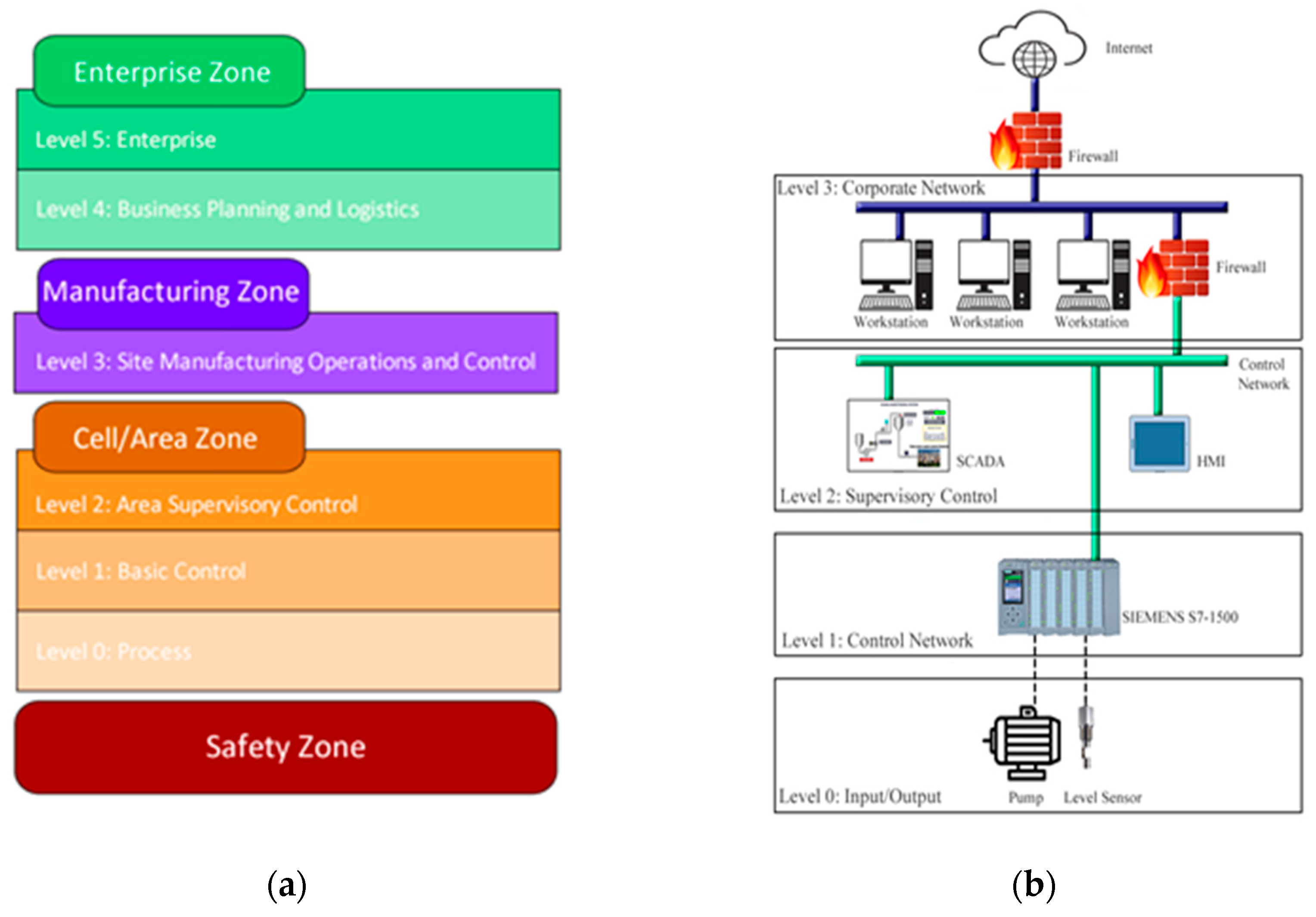
3.1. ICS Architecture
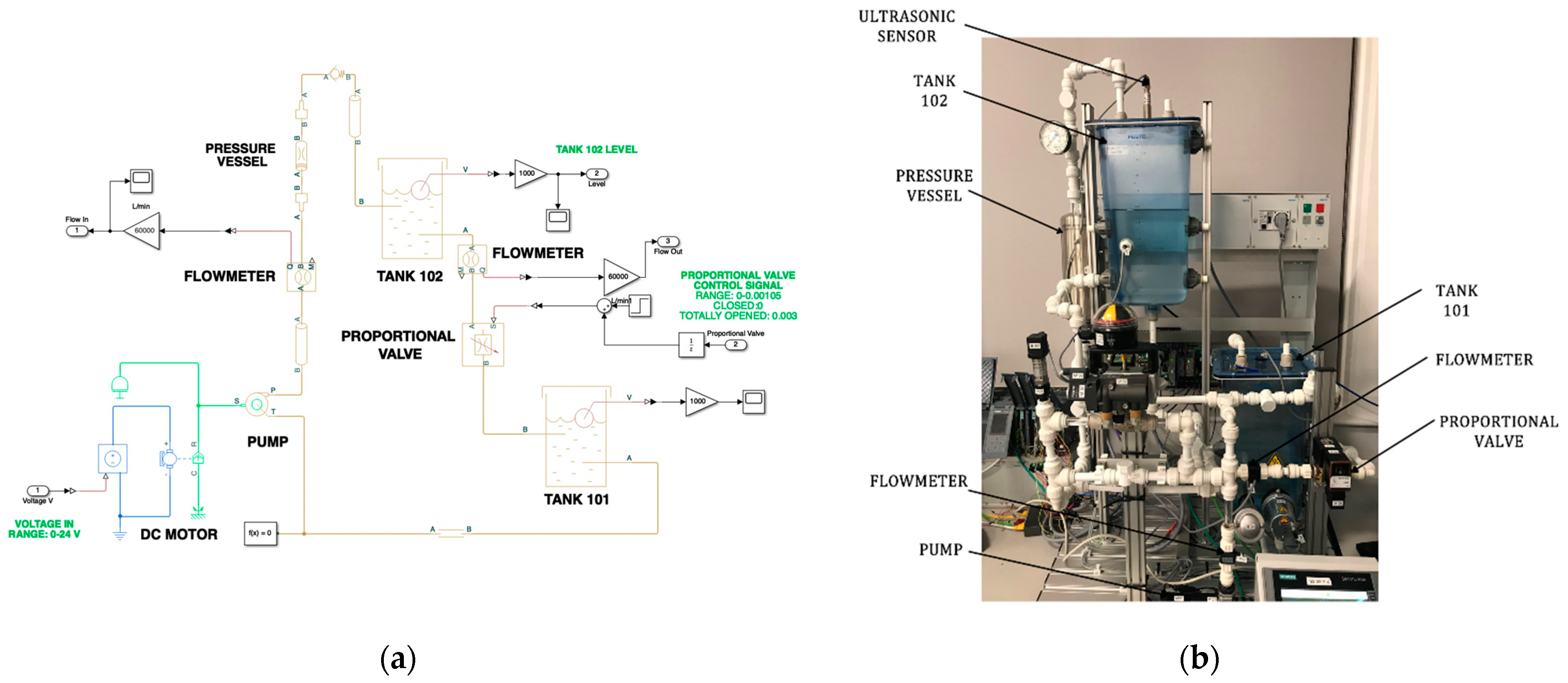
ICSs are composed of different elements such as electrical, mechanical, and pneumatic that are used to achieve various objectives in industries like manufacturing or transportation. There are several guidelines, security standards, and best practices on ICS risk management. For example, IEC/ISA-62443 [20], which is an ICS security standard, or the UK’s CPNI [21], which provides a practice guide for ICS security. As the researchers in [22] state, and we also agree, two important guides that describe the ICS architecture are NIST 800-82 [23] and the Purdue model suggested by SANS [24]. The representation of these two architectures is shown in Figure 1.
Figure 1. Industrial Control System (ICS) Architecture: (a) 1 Purdue Model for Control Hierarchy logical framework; (b) ICS reference model.
The Purdue Model for control hierarchy logical framework provides a more detailed classification in comparison with the NIST model. Purdue model identifies four zones and six levels as it is depicted in Figure 1. The Safety Zone is an air-gapped system that alert operators about unsafe conditions. The Cell/Area Zone is defined as a functional area within a production facility while the Manufacturing Zone comprises the Cell/Area networks and site-level activities. The Enterprise Zone is where business systems such as Enterprise Resource Planning (ERP) and System Applications and Products (SAP) typically reside. Each zone has a sub-classification represented as levels and each level is a logic segment of an ICS that performs a specific function.
NIST states that an ICS should focus on four general areas: the control centre, the communication architecture, the field devices, and the physical process itself. Figure 1 shows the ICS reference model suggested by NIST. Level 0 includes hardware such as sensors that compose the control system, while Level 1 involves control equipment such as PLCs. At Level 2, equipment that monitors and control the operation of the process such as SCADA system and HMI resides, whereas the corporate network is part of Level 3.
Purdue Model includes a safety zone which is not described in the SANS model. Both models include HMI in addition to other equipment at Level 2, but it does not comprise of SCADA systems given that they belong to Level 3. In both models, Level 0 includes sensors and actuators that are connected to the physical process. For instance, ultrasonic sensors, flowmeters, pressure sensors, valves, and pumps can be found in Level 0. Level 1 involves equipment that controls sensors and actuators found at the previous level (i.e., Level 0). For instance, devices such as PLC are placed at Level 1. The PLC receives information from the physical process through hard-wired sensors, then it processes such information using control techniques like Proportional Integral Derivative (PID), The Cascade, and Feed Forward. Finally, it controls actuators like pumps and valves.

3.2. Virtual Plant

The virtual plant developed for this research simulates the operation of the physical process implemented in the Festo rig. To achieve this, we use Simulink [25] which is a MATLAB graphical editor for modelling and simulating dynamic systems. Figure 2 shows the virtual representation of the Festo Rig, and its physical components. The virtual plant is composed of elements with the same characteristics and properties as the physical components. To achieve such similarity, we built the virtual sensors/actuators from the information obtained from the Festo Rig datasheet [26]. The virtual plant elements are as follow.
Figure 2. Hybrid testbed: (a) CWSS virtual process; (b) Festo rig components.
Pipes: The diameter of the pipes used in the virtual model is 18.621 mm.
Pressure Vessel: The pressure vessel acts as a normal pipe; however, its shape causes a small drop in the water pressure. We model this component as a sudden change in the pipeline. The diameter of both ends corresponds to the diameter of the pipe, which is 18.621 m. The diameter at the centre of the pressure vessel is calculated using the Equation (1). The volume (Vol) is obtained from the Festo rig datasheet, while h represents the height of the vessel.
d =   V o l π h
Pump: The virtual pump is composed of several components. A motor controller which supplies a voltage in the range of 0 to 24 volts, a DC Motor, and a centrifuge pump.
Proportional Valve: The proportional valve simulates the water demand of a town. The virtual valve operates with the same water demand models implemented in the physical valve. It is implemented as a variable orifice valve. Its range of operation is determined during the experimentation phase.
Water Tanks: The water tanks have a variable cross-section area. The first step is to obtain the measurements of the physical tanks. Then, the virtual tanks are created from these measurements.
Flowmeters: The physical flowmeters are represented as hydraulic flow rate sensors.
Ultrasonic Sensor: The ultrasonic sensor is not implemented in the virtual testbed. The virtual tanks provide its fluid level.

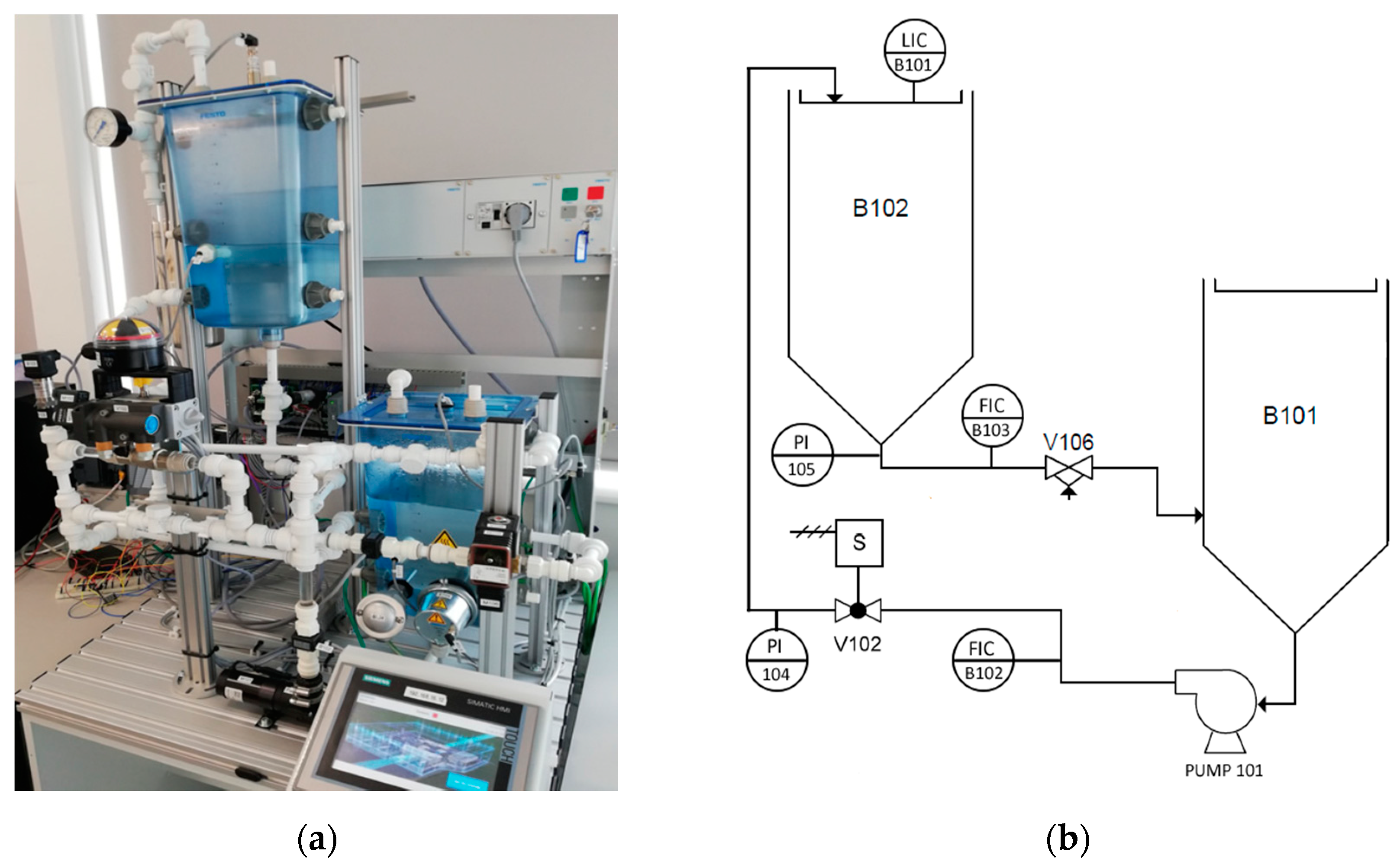
3.3. Physical Testbed (CWSS-P)

The CWSS testbed physically models a continuous clean water supply system using a custom configuration of the Festo MPS PA Compact Workstation Rig [26] shown in Figure 2. This testbed distributes its components in three levels, according to the ICS reference model shown in Figure 1.
Layer 0 comprises of sensors/actuators involved in the physical process. These devices are described as follows:
  • One Ultrasonic sensor.
  • Two Flowmeters.
  • Two Pressure Sensors.
  • One Pump.
  • One Solenoid Valve.
  • One Proportional Valve.
Level 1 involves a Siemens S7-1500 PLC [27] that is used to control the system operation by using the information provided by the sensors located at Level 0.
Level 2 includes equipment that monitors the status of the process through the information provided by the PLC. The equipment used to test and exploit vulnerabilities are also in this level. This equipment is described as follows:
  • SCADA system running Windows 10.
  • Siemens HMI.
  • An attacker machine running Kali OS.

3.3.1. Normal Operation

In normal operation, the tank B102, shown in Figure 3, represents a reservoir of water to be maintained at a specified level. The tank B101 contains the water supply simulating the natural water table and feeds tank B102 through the variable speed pump (P101). Unlike the existing research, the CWSS testbed implements a set of daily water demand models using the proportional valve (V106). This allows us to implement a more realistic testbed. Further information regarding this water demand model is fully described in our previous work [28].
Figure 3. Physical testbed diagram: (a) Festo MPA Process Control Rig.; (b) Festo MPA Process Control Rig Diagram.

3.3.2. PLC Programming

PLC coding is an important task. The proper design and implementation guarantee the correct operation of the system. At the same time, it can hugely contribute as a layer of protection against intruders. As described in our previous work [28], the PLC contained an embedded mechanism of cyberattack detection and response. Among those, this testbed implements PID, Cascade and feedforward controller described as follows in addition to Table 1.
Table 1. Control techniques implemented at the CWSS testbed.
PID Controller: The PID controller is an instrument used in industrial control applications and consists of three basic control actions: proportional, integral, and derivative to regulate temperature, flow, pressure, speed, and other process variables. (OP) [29].
Cascade Controller: Cascade Control is an advanced PID implementation that can improve ICS that are subject to significant delay. [1].
Feedforward Controller: Feedforward control systems measure the disturbance and modify the controller output before the process variable has time to respond. For this to be successful, the designer is required to understand how the disturbance will affect the process variable [30]. Sensors and tags can be found in Figure 3.

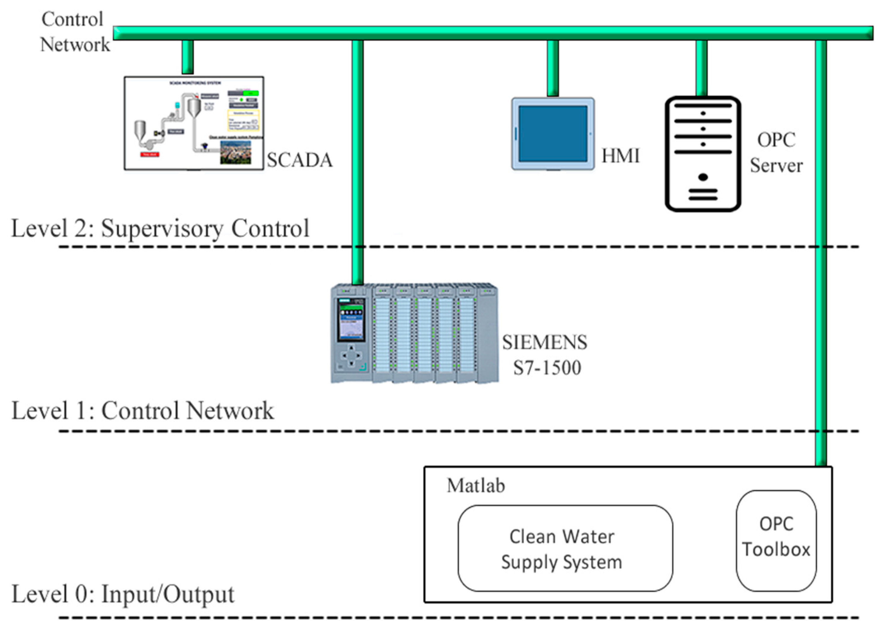
3.4. Hybrid Testbed (CWSS-H)

Figure 4 shows the hybrid testbed architecture. It adopts the three levels explained at the physical testbed, the main difference is that sensors/actuators that compose the Festo rig are simulated in MATLAB.
Figure 4. CWSS-H testbed architecture.
Therefore, the virtual testbed is located at Level 0. The Siemens S7-1500 PLC receives information from the virtual sensors and commands the speed of the virtual pump through the OPC server. To allow such communication, it is required to disable the memory optimisation feature in the PLC. The main issue found when disabling memory optimisation is that with disabling the memory optimisation intruders can access and manipulate those spaces of memory. This configuration makes the hybrid system more vulnerable compared to the physical system. Our previous work shows the importance of features like memory optimisation and how they prevent unauthorised memory access [28].

OPC Server and Client

OPC is a software interface standard that allows communication between industrial equipment and computers [31]. The implementation of OPC specifications involves two parts: OPC Server application and OPC client application. The OPC server obtains information from PLC and sends it back to OPC client application using the standard OPC protocol. In our hybrid testbed, the OPC toolbox [32] in MATLAB sends the virtual tank level to the OPC server. This value is used in the physical PLC as the Process Variable (PV) for the Proportional-Integral PI controller that calculates the required speed of the virtual pump. The OPC server recovers this value and the water demand from the PLC working memory. These values are sent back to the OPC client in MATLAB. The communication between the PLC, OPC Server, and MATLAB is through the OPC protocol that runs over the TPC/IP network.

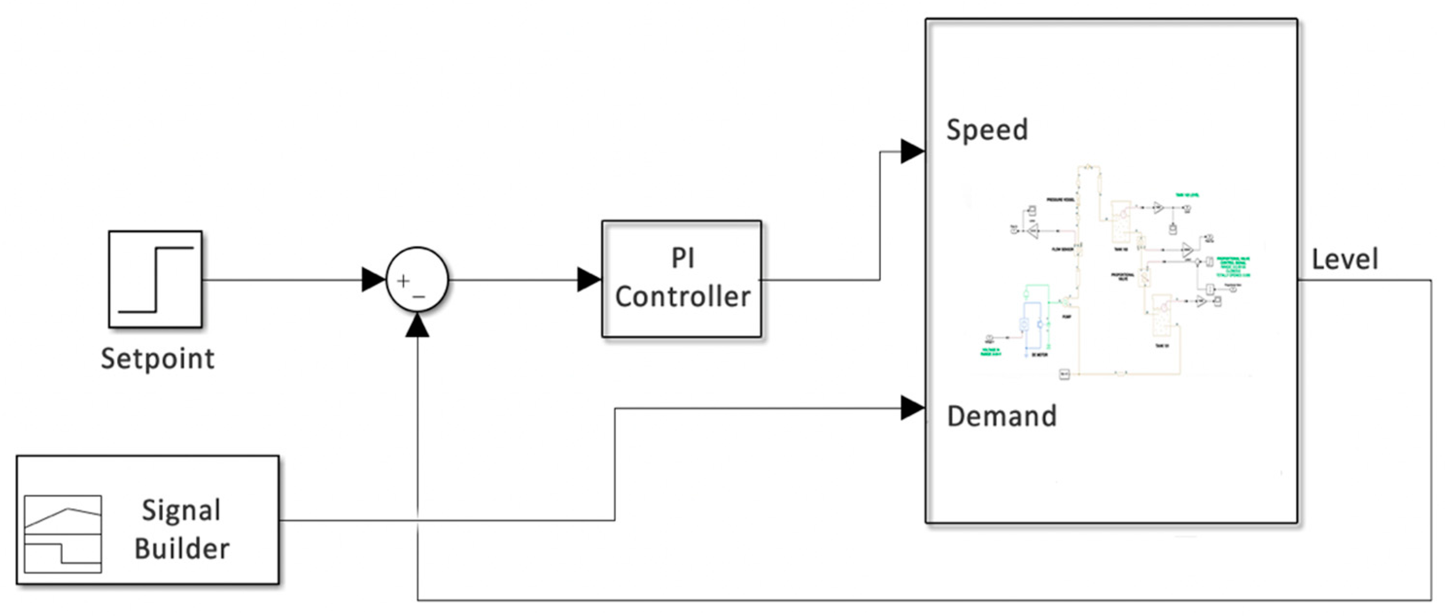
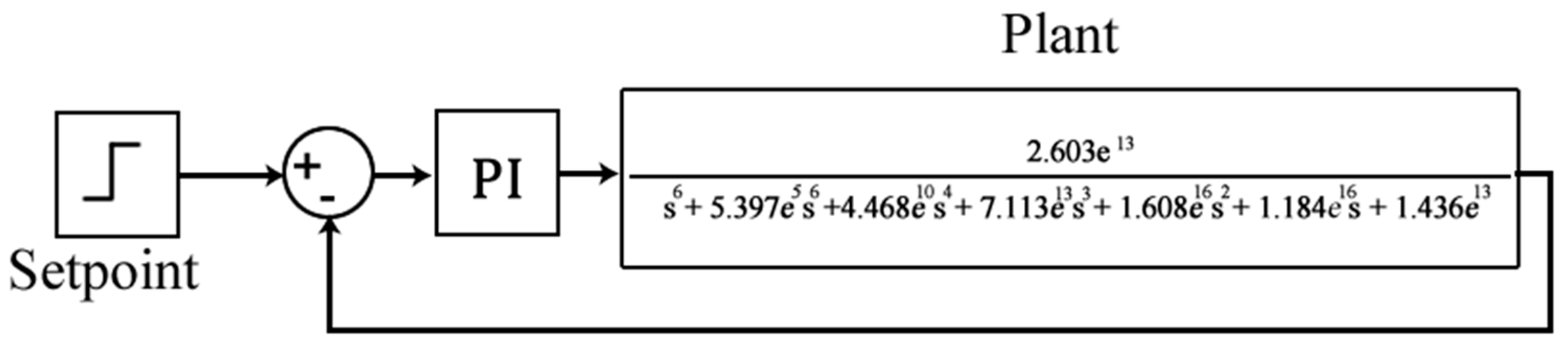
3.5. Virtual Testbed (CWSS-V)

The CWSS virtual testbed (CWSS-V) is entirely implemented in MATLAB. In comparison with the physical and hybrid testbeds, the virtual testbed is composed of two levels. Level 0 includes the virtual sensors/actuators while the PLC is replaced by the PI controller at Level 1. Figure 5 shows the virtual testbed. The virtual control process is the same used in the hybrid testbed. The input parameters are the speed of the pump, which is given by the PI controller. Another input is the water demand, which is generated by a tool called: Signal Builder. The PI controller uses the same values of proportional and integral used in the physical PLC, while the signal builder replicates the water demand model used in the previous testbeds CWSS-P and CWSS-H.
Figure 5. CWSS-V testbed.
The virtual representation of this testbed, shown in Figure 5, was derived using MATLAB tools in the form of a Transfer Function (TF). This was achieved by interfacing MATLAB to the testbed using an OPC server to stimulate the real test rig via the pump and observe its response. From spotting these replies, MATLAB can estimate the system behaviour in terms of a mathematical representation of the system dynamics in the frequency domain using the Laplace operator. This operator is given by the divergence of the gradient of a function on Euclidian space [25]. The TF defines the relationship between the system output (tank level) in response to the input stimuli (pump speed command) i.e., open loop. The TF models all the physical system components mathematically. The derived transfer function of our system is a sixth-order polynomial as shown in Equation (2).
2.603 e 13 s 6 + 5.397 e 05 s 6 + 4.468 e 10 s 4 + 7.113 e 13 s 3 + 1.608 e 16 s 2 + 1.184 e 16 s + 1.436 e 13
We can fully simulate the closed-loop response by adding a mathematical model of a Proportional Integral (PI) controller as shown in Figure 6. This allows us to evaluate the closed-loop response of the system.
Figure 6. CWSS Transfer Function.

4. Testbed Evaluation

This section shows the evaluation of our three testbeds (CWSS-P, CWSS-H, and CWSS-V) from the cyber-security perspective.

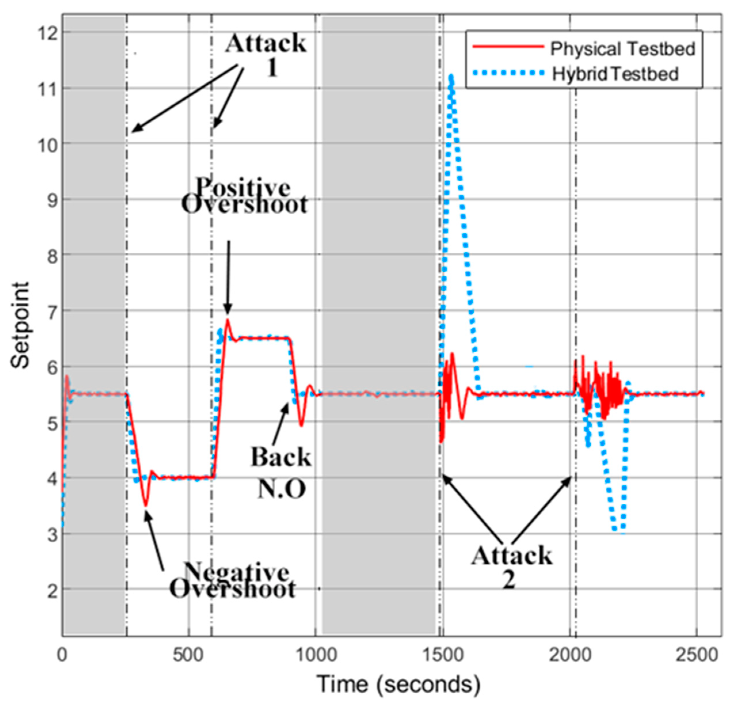
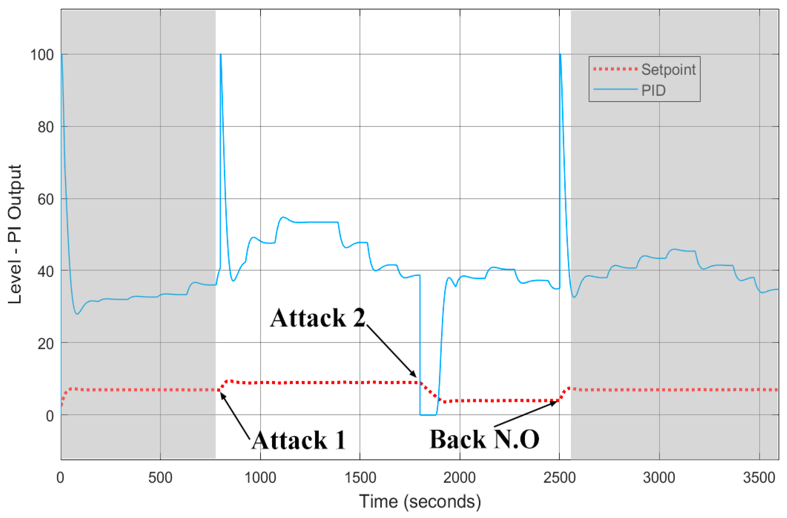
4.1. Attack Scenarios

The evaluation of the physical and hybrid testbeds against cyber threats is performed by assuming that an attacker has access to the control network. In our scenario, the attacker has gained access at Level 1 of the ICS architecture. The attacker crafts ISO 8073/X.224 COTP packets and sends over the TCP/IP network aiming to overwrite fixed spaces of memory in the PLC [33]. These novel attacks are fully explained in our previous works [34,35]. The attacks used to evaluate the physical and hybrid testbeds are performed against the input and working memory of the PLC. The values modified belong to the ultrasonic sensor at the input memory and setpoint at the working memory. Those attacks cannot be executed on the virtual testbed given that it does not have a physical PLC; however, for evaluation purposes, we mimic those attacks by tampering the values of feedback of the PI controller in the virtual testbed. This clearly points out one of the limitations of virtual testbeds.

4.2. Physical and Hybrid Testbeds

The CWSS-P and CWSS-H testbeds are executed at the same time aiming to compare their performance during normal operation and under attack scenarios. Figure 7 shows the monitoring of the process variable (setpoint) of CWSS-P and CWSS-H testbeds during both operations.
Figure 7. CWSS-P and CWSS-H during normal operation and attack conditions.
Moreover, the grey area in Figure 7 shows the normal operation of CWSS-P and CWSS-H testbeds. The setpoint of the virtual and physical tank in both testbeds remains steady during normal conditions. This demonstrates that the virtual model of the Festo Rig performs like the physical rig during normal operation. Furthermore, Figure 7 shows the behaviour of the testbeds when two attacks were executed against the input memory and working memory of the PLC. Attack 1 represents a sudden change in the working memory addressed to the setpoint. When the setpoint changes both testbeds have almost the same response. The main difference between them is positive and negative overshoot. The response of the CWSS-H testbed has more linearity than the CWSS-P. This can be attributed to the hybrid testbed being mathematically built in MATLAB, while the physical components of the CWSS-P have dynamics that cannot be simulated. After the execution of Attack 1, the system returns to the initial setpoint. This change is shown in Figure 7 with the label Back N.O.
Attack 2 shown in Figure 7, denotes the attack executed against the space of memory addressed to the input memory of the PLC. The attacker modifies the values of the physical and virtual level sensors, as a result, the water level in the physical and virtual tanks changes. During the execution of this attack, the behaviour of the CWSS-P and CWSS-H testbeds differs. The reason for this behaviour difference is because the CWSS-H testbed does not take the PI values directly from the PLC, instead it retrieves it from the OPC server. This adds a small delay in the control process that is not significant for its operation, but it represents a serious threat when the process is under attack because sensitive values such as the tank level can be modified. As shown in Figure 7, the execution of attack 2 on the CWSS-H testbed results in an overflow or emptying of the virtual tank 102. Attack 2 executed on the CWSS-P testbed produces an increase/decrease of the water level at the physical tank 102. Although the attack does not show the same behaviour as the one shown in CWSS-H, this can affect other components of the CWSS-P testbed such as the pump. The change of the setpoint during the attack is given by the sudden change of speed in the pump. If the attack continues indefinitely, the pump might overheat and stop its operation, which will affect the entire control process.

4.3. Virtual Testbed

The grey area shown in Figure 8 represents the normal operation of the CWSS-V while the arrows point to the two attacks executed against the setpoint during the operation of the system. On the same Figure, the red dotted line represents the water level at the virtual reservoir tank and the blue line denotes the output of the PI controller, which is the input voltage that regulates the pump speed. The first attack executed increases the setpoint by 2 L, which also produces a sudden increase in the output of the PI controller as it can be seen in Figure 8. This is because the controller detects a mismatch between the current water level and the new value entered by the attacker in the system. As a result, the PI controller increases its output, which represents the pump speed, until it reaches the new setpoint.
Figure 8. CWSS Virtual Plant Normal Operation.
In the second attack, in Figure 8, the intruder decreases the setpoint by 6 L. The controller output is reduced to 0 because the current water level exceeds the setpoint set by the attacker. As a result, the pump stops its operation until the new setpoint is reached.
The time it takes to arrive at this new setpoint depends on the demand for water at that time. At the end, the system returns to its normal setpoint. Figure 9 shows a closed-loop control system composed of the transfer function that represents the CWSS virtual process and a PI controller. The dotted line represents the setpoint, while the continuous line represents the output of the PI controller. The grey area represents the normal operation of the system. The operation of the system is completely linear. This is a result of the fact that the closed-loop control system only takes an input parameter, which is the output of the PI controller. Parameters such as water demand are ignored in this simulation.
Figure 9. CWSS Transfer function.
Further, in Figure 9, the controller’s output does not change during normal system operation. It only changes when the attacks are executed. In Attack 1, the intruder increases the setpoint, which produces an immediate change in the output of the PI controller until the new setpoint is reached. The intruder decreases the setpoint of the system in attack 2. The output of the PI controller is reduced to zero until the new setpoint is established. The discharge of the tank is linear due to the fact this simulation does not implement water demand models.

5. Discussion

This section addresses the research questions raised at the beginning of this paper, as well as compares the testbeds implemented in this research with the related work detailed in Section 2.

5.1. Research Questions

Research Question 1. How does a hybrid and virtual implementation of a clean water supply system differ during normal operation and under attack scenarios in comparison with the physical model of such system?
According to the results obtained from the experimentation described in this paper, the CWSS-H testbed has the same performance as the CWSS-P testbed under normal conditions and when the first attack to the setpoint is executed. This performance can be seen in Figure 7. However, in the second attack, when the intruder modifies the input memory of the PLC, the behaviour of the CWSS-H testbed differs from the CWSS-P testbed. The delay that the OPC server adds to the CWSS-H testbed allows the attacker to take full control of the values provided by the PLC to the virtual system in MATLAB. Furthermore, the lack of physical components in the virtual testbed such as the PLC does not allow to run it along with the physical testbed. Furthermore, the virtual testbed is limited to one simulated attack which is a change of setpoint. The results obtained from the experimentation phase show that the hybrid testbed shows a similar operation to the physical testbed. The CWSS-V testbed can provide insights about the operation of the system under normal conditions, but under attack, the results are uncertain and limited given that the implementation of novel attacks is almost impossible. For example, the attacks on the PLC memory, like the ones described in this paper, cannot be executed in a virtual environment.
Research Question 2. Can we rely on mechanisms of anomaly detection on ICS which are developed and tested on virtual platforms?
The comparison of the physical, hybrid, and virtual testbeds, shown in this paper, demonstrate that each testbed has a different behaviour when a cyber-attack occurs. The virtual testbed has a notable limitation when it is compared with the rest of the testbeds. For instance, the novel set of attacks against the PLC memory described in this paper cannot be implemented in a virtual environment because it does not implement a physical PLC. Thus, we can argue that the mechanisms of attack detection developed in virtual environments might not be accurate at detecting cyber-attacks when they are deployed in physical environments.

5.2. Testbed Comparison

Table 2 provides a summary of the testbeds described in the related work and the testbeds implemented in this research. The physical testbeds provided by the authors [6,7,8,9] which are related to the physical testbed implemented in our research, operate with the protocol Modbus TCP which is known for having a considerable number of vulnerabilities [36,37]. Thus, the impact of cyber-attacks to critical infrastructures that operate with Modbus protocol has been extensively explored. In this research, we propose a more realistic set of attacks that can occur in a real scenario, those attacks target the Siemens PLC memory with the aim of overwriting it. Unlike attacks like Man-In-The-Middle, Dos, ARP Spoofing, which are used in related work and have been widely explored in different investigations.
Table 2. ICS testbeds for cyber-security research.
The hybrid testbeds implemented in related works [11,12,13,14] also lack the implementation of a novel set of attacks employed during the validation tests, while in our research we still implement the set of attacks targeting the PLC memory. Furthermore, our virtual process implemented in MATLAB is composed of sensors and actuators with the same properties as physical sensors and actuators. In addition, during the creation of the virtual process, the performance of the physical and virtual process was compared during the different stages of the implementation. It is worth mentioning that it is not clear if the virtual processes implemented in the related work are implemented based on their physical counterpart.
The virtual testbed implemented in this research uses the same virtual process employed by the hybrid testbed. The main difference lays in the set of attacks used against the control process. It can be determined that cybersecurity research in virtual testbeds does not allow to have a real perspective of the impact that cyber-attacks have on control processes. For this reason, it is advisable to use real control processes implemented with physical equipment, thus, it is possible to determine the impact of cyber-attacks.

6. Conclusions

This paper compares a physical, hybrid, and virtual testbed operation from a cybersecurity perspective. Under normal operation the physical and hybrid testbeds show similar behaviour; however, their behaviour is different when they are under attack. Furthermore, the virtual testbed shows many limitations when implementing the attack scenarios. For this testbed, it is difficult to replicate attacks to the input memory of the PLC, although, it is feasible to modify the setpoint. The mathematical equation obtained from the physical system serves only to show a representation of the control process, however, it can be argued whether a security system such as an IDS can be built based on the represented mathematical equation.
The cyber-attack detection mechanisms in ICS require a comprehensive understanding of the system operation. Achieving this knowledge through the information obtained from virtual simulation environments is complex and often impossible. The physical dynamics of the components such as sensors and actuators cannot be simulated in a virtual environment. Therefore, in our point of view, it is unrealistic and rather unsafe to rely on detection mechanisms created in virtual environments. According to the results obtained during the experimentation phase, the physical environments allow us to visualise the behaviour of cyber-attacks in a real ICS with the aim of providing an accurate and efficient mechanism of cyber-attack detection.

Author Contributions

Conceptualization, A.R.-D.; N.M.; J.M.; methodology, A.R.-D.; N.M.; J.M.; J.P.-B.; software, A.R.-D.; N.M.; J.M.; J.P.-B.; validation, A.R.-D.; N.M.; J.M.; J.P.-B.; formal analysis, A.R.-D.; N.M.; J.M.; J.P.-B.; investigation, A.R.-D.; N.M.; J.M.; J.P.-B.; resources, A.R.-D.; N.M.; J.M.; J.P.-B.; data curation, A.R.-D.; N.M.; J.M.; J.P.-B.; writing—original draft preparation, A.R.-D.; N.M.; J.M.; writing—review and editing, A.R.-D.; N.M.; visualization, A.R.-D.; N.M.; J.M.; J.P.-B.; supervision, N.M.; J.M.; G.R.; project administration, A.R.-D.; N.M.; J.M.; J.P.-B.; funding acquisition, N.M.; J.M. All authors have read and agreed to the published version of the manuscript.

Funding

This research was funded by Edinburgh Napier University as a joint PhD project between the School of Computing and the School of Engineering & Built Environment.

Institutional Review Board Statement

Not applicable.

Data Availability Statement

The data presented in this study are available on request from the corresponding author.

Conflicts of Interest

The authors declare no conflict of interest.

References

  1. Kamel, K.; Kamel, E. Introduc tion to PLC control systems and automation. In Programmable Logic Controllers: Industrial Control; McGraw-Hill Education: New York, NY, USA, 2014; pp. 1–31. [Google Scholar]
  2. Critical National Infrastructure. Available online: https://www.cpni.gov.uk/critical-national-infrastructure-0 (accessed on 7 October 2020).
  3. Critical Infrastructure Sectors. Available online: https://www.cisa.gov/critical-infrastructure-sectors (accessed on 5 October 2020).
  4. Langner, R. Stuxnet: Dissecting a Cyberwarfare Weapon. IEEE Secur. Priv. Mag. 2011, 9, 49–51. [Google Scholar] [CrossRef]
  5. Mathur, A.P.; Tippenhauer, N.O. SWaT: A water treatment testbed for research and training on ICS security. In Proceedings of the 2016 International Workshop on Cyber-physical Systems for Smart Water Networks (CySWater), Vienna, Austria, 11 April 2016; pp. 31–36. [Google Scholar]
  6. Ahmed, C.M.; Palleti, V.R.; Mathur, A.P. WADI: A water distribution testbed for research in the design of secure cyber physi-cal systems. In CySWATER ’17: Proceedings of the 3rd International Workshop on Cyber-Physical Systems for Smart Water Networks, Pittsburgh, PA, USA, 21 April 2017; ACM: New York, NY, USA, 2017; pp. 25–28. [Google Scholar]
  7. Secure Water Treatment. Available online: https://itrust.sutd.edu.sg/testbeds/secure-water-treatment-swat/ (accessed on 21 September 2020).
  8. Miciolino, E.E.; Bernieri, G.; Pascucci, F.; Setola, R. Communications network analysis in a SCADA system testbed under cyber-attacks. In Proceedings of the 2015 23rd Telecommunications Forum Telfor (TELFOR), Belgrade, Serbia, 24–26 November 2015; Volume 7, pp. 341–344. [Google Scholar]
  9. Ahmed, I.; Roussev, V.; Johnson, W.; Senthivel, S.; Sudhakaran, S. A SCADA System Testbed for Cybersecurity and Forensic Research and Pedagogy. In Proceedings of the 2nd Annual Industrial Control System Security Workshop on—ICSS ’16, Los Angeles, CA, USA, 6 December 2016; ACM: New York, NY, USA, 2016; Volume 16, pp. 1–9. [Google Scholar]
  10. Siemens S7-300/400 PLC Vulnerabilities (Update E). Available online: https://www.us-cert.gov/ics/advisories/ICSA-16-348-05 (accessed on 21 October 2019).
  11. Keliris, A.; Salehghaffari, H.; Cairl, B.; Krishnamurthy, P.; Maniatakos, M.; Khorrami, F. Machine learning-based defense against process-aware attacks on Industrial Control Systems. In Proceedings of the 2016 IEEE International Test Conference (ITC), Fort Worth, TX, USA, 15–17 November 2016; pp. 1–10. [Google Scholar] [CrossRef]
  12. Rosa, L.; Cruz, T.; Simoes, P.; Monteiro, E.; Lev, L. Attacking SCADA systems: A practical perspective. In Proceedings of the 2017 IFIP/IEEE Symposium on Integrated Network and Service Management (IM), Lisbon, Portugal, 8–12 May 2017; pp. 741–746. [Google Scholar] [CrossRef]
  13. Xie, Y.; Wang, W.; Wang, F.; Chang, R. VTET: A Virtual Industrial Control System Testbed for Cyber Security Research. In Proceedings of the 2018 Third International Conference on Security of Smart Cities, Industrial Control System and Communications (SSIC), Shanghai, China, 18–19 October 2018; pp. 1–7. [Google Scholar] [CrossRef]
  14. Ghaleb, A.; Zhioua, S.; Almulhem, A. SCADA-SST: A SCADA security testbed. In Proceedings of the 2016 World Congress on Industrial Control Systems Security (WCICSS), London, UK, 2–14 December 2016; pp. 1–6. [Google Scholar] [CrossRef]
  15. Tesfahun, A.; Bhaskari, D.L. A SCADA testbed for investigating cyber security vulnerabilities in critical infrastructures. Autom. Control. Comput. Sci. 2016, 50, 54–62. [Google Scholar] [CrossRef]
  16. Almalawi, A.; Tari, Z.; Khalil, I.; Fahad, A.; Khalil, I. SCADAVT-A framework for SCADA security testbed based on virtualization technology. In Proceedings of the 38th Annual IEEE Conference on Local Computer Networks, Sydney, NSW, Australia, 21–24 October 2013; pp. 639–646. [Google Scholar]
  17. Rossman, L.A. Epanet 2. September 2000. p. 104. Available online: https://www.microimages.com/documentation/Tutorials/Epanet2UserManual.pdf (accessed on 15 October 2019).
  18. Hadiosmanovio, D.; Sommer, R.; Zambon, E.; Hartel, P.H. Through the eye of the PLC: Semantic security monitoring for industrial processes. In Proceedings of the 30th Annual Computer Security Applications Conference, Orleans, LA, USA, 8–12 December 2014; ACM: New York, NY, USA, 2014; pp. 126–135. [Google Scholar]
  19. Mallouhi, M.; Al-Nashif, Y.; Cox, D.C.; Chadaga, T.; Hariri, S. A testbed for analyzing security of SCADA control systems (TASSCS). In ISGT 2011, Anaheim, CA, USA, 17–19 January 2011; IEEE: New York, NY, USA, 2011; pp. 1–7. [Google Scholar] [CrossRef]
  20. Phinney, T. IEC 62443: Industrial Network and System Security, Isa. 2006. Available online: https://www.isa.org/getmedia/b75b5611-1fa8-4807-99e5-d8707b7cff18/Phinneydone.pdf (accessed on 15 October 2019).
  21. Luzia, K.; Cole, B.; Allen, P.; Clark, J.; Jones, A.; Lawrence, J.; Burns, L.S.; Thomas, T.; Wallace, J.; Wallace, J. Good Practice Guide. 2015. Available online: https://ltr.edu.au/resources/ID12-2470_ACU_Thomas_Geography%20-%20Good%20Practice%20Guide.pdf (accessed on 15 October 2019).
  22. Ogundokun, A.; Zavarsky, P.; Swar, B. Cybersecurity assurance control baselining for smart grid communication systems. In Proceedings of the 2018 14th IEEE International Workshop on Factory Communication Systems (WFCS), Imperia, Italy, 13–15 June 2018; pp. 1–6. [Google Scholar] [CrossRef]
  23. Stouffer, K.; Pillitteri, V.; Lightman, S.; Abrams, M.; Hahn, A. Guide to Industrial Control Systems (ICS) Security. 2015. Available online: https://www.nist.gov/publications/guide-industrial-control-systems-ics-security (accessed on 15 October 2019).
  24. Obregon, L.; Filkins, B. Secure Architecture for Industrial Control Systems. 2020. Available online: https://www.semanticscholar.org/paper/Secure-Architecture-for-Industrial-Control-Systems-Obregon-Filkins/f13663f1760d269e87f6d7e5e8fef360fe6b1853 (accessed on 15 October 2019).
  25. Kollár, I.; Pintelon, R.; Schoukens, J. Frequency Domain System Identification Toolbox for MATLAB. IFAC Proc. Vol. 1991, 24, 1243–1247. [Google Scholar] [CrossRef]
  26. MPS PA Compact Workstation with Level, Flow Rate, Pressure and Temperature Controlled Systems. Available online: https://www.festo-didactic.co.uk/gb-en/learning-systems/process-automation/compact-workstation/mps-pa-com-pact-workstation-with-level,flow-rate,pressure-and-temperature-controlled-systems.htm?fbid=Z2IuZW4uNTUwLjE3LjE4Ljg4Mi40Mzc2 (accessed on 7 July 2018).
  27. Our Fastest Controller for Automation. Available online: https://www.siemens.com/global/en/home/products/automation/systems/industrial/plc/simatic-s7-1500.html (accessed on 9 November 2015).
  28. Robles-Durazno, A.; Moradpoor, N.; McWhinnie, J.; Russell, G.; Maneru-Marin, I. PLC memory attack detection and response in a clean water supply system. Int. J. Crit. Infrastruct. Prot. 2019, 26, 100300. [Google Scholar] [CrossRef]
  29. Ang, K.H.; Chong, G.; Li, Y. PID control system analysis, design, and technology. IEEE Trans. Control. Syst. Technol. 2005, 13, 559–576. [Google Scholar] [CrossRef]
  30. Industrial Control Systems. Available online: https://www.us-cert.gov/ics (accessed on 15 May 2020).
  31. Vardar, E.; Giraz, A.H.; Örenbaş, H.; Şahin, S. OPC server based and real time motor speed control with PLC communication system. In Proceedings of the 26th IEEE Signal Processing and Communications Applications Conference (SIU), Izmir, Turkey, 2–5 May 2018; pp. 1–4. [Google Scholar]
  32. OPC Toolbox 2020. Available online: https://uk.mathworks.com/products/opc.html (accessed on 8 October 2019).
  33. Packet Crafting, Scapy and S7-1500 PLC. Available online: https://github.com/andrex17/ics (accessed on 6 April 2019).
  34. Robles-Durazno, A.; Moradpoor, N.; McWhinnie, J.; Russell, G.; Maneru-Marin, I. Implementation and Detection of Novel Attacks to the PLC Memory of a Clean Water Supply System. In Communications in Computer and Information Science; Springer: Cham, Germany, 2018; Volume 895, pp. 91–103. [Google Scholar]
  35. Robles-Durazno, A.; Moradpoor, N.; McWhinnie, J.; Russell, G. WaterLeakage: A Stealthy Malware for Data Exfiltration on Industrial Control Systems Using Visual Channels*. In Proceedings of the 2019 IEEE 15th International Conference on Control and Automation (ICCA), Edinburgh, UK, 16–19 July 2019; pp. 724–731. [Google Scholar]
  36. Nyasore, O.N.; Zavarsky, P.; Swar, B.; Naiyeju, R.; Dabra, S. Deep Packet Inspection in Industrial Automation Control System to Mitigate Attacks Exploiting Modbus/TCP Vulnerabilities. In Proceedings of the 2020 IEEE 6th Intl Conference on Big Data Security on Cloud (BigDataSecurity), IEEE Intl Conference on High Performance and Smart Computing, (HPSC) and IEEE Intl Conference on Intelligent Data and Security (IDS), Baltimore, MD, USA, 25–27 May 2020; pp. 241–245. [Google Scholar]
  37. Wenqian, F.; Yingxu, L.; Zenghui, L. Vulnerability mining for Modbus TCP based on exception field positioning. Simul. Model. Pract. Theory 2020, 102, 101989. [Google Scholar]
Publisher’s Note: MDPI stays neutral with regard to jurisdictional claims in published maps and institutional affiliations.

Article Metrics

Citations

Article Access Statistics

Multiple requests from the same IP address are counted as one view.