1. Introduction
Aimed at actual processing needs of the automotive, aerospace, military, and other industries, Turn-Milling combined NC machine tool can not only carry out turning, milling, drilling, grinding, and other multi-process compound processing, the use of multi-axis linkage function can also complete the inclined parts and complex space surface processing, which is greatly improving the processing efficiency and accuracy. At the same time, with the further development of processing technology, some scholars and researchers have carried out remarkable researches to improve the processing quality of workpieces. Radoslaw et al. [
1] presented a comprehensive approach to surface formation after machining with different cooling/lubricating techniques. Nieslony et al. [
2] used some physical and technological aspects of a precise turning with Self-Propelled Rotary Tool. Marta et al. [
3] illustrated the influence of manufacturing technology, cutting speed, and feed ratio on selected surface parameters of samples was made. Wojciechowski et al. [
4] proposed the prediction of cutting forces during micro end milling using a novel approach that takes into account the chip thickness accumulation phenomenon.
Geometric error modeling can significantly improve the performance of machine tools in the design process. The key to research in error modeling techniques is to find a more effective modeling method to accurately reflect the error of the machine tool through the established model. The research of machine tool error modeling method has been developed for a long time. Existing machine tool error modeling technology research toward multi-axis, multi-error, multi-factor direction, all kinds of research results and practical applications more closely integrated. Most of the existing techniques are based on the theory of multibody system theory (MBS) using the homogeneous coordinate transformation method.
Tao et al. [
5] used matrix decomposition method to simplify the calculation of tool position error in the volumetric error model based on MBS. Further-more, Tao developed a geometric error model for the turning process on an ultra-precision lathe based on MBS [
6], and the machining accuracy of workpieces can be improved by crucial geometric error compensation. Guo et al. [
7] established a synthetic geometric error model for a five-axis machine tool with tilting head and turntable based on the MBS and the method of homogeneous coordinate transformation. Based on the theory of MBS, Chen et al. [
8] established an error model of angular measurement with geometric errors of a torsional characteristic measurement system based on MBS, which can effectively predict the angular measurement error. Other new theories have been applied to modeling machine tool errors, such as screw theory. Zhang et al. [
9] dealt with geometric error modeling and sensitivity analysis of an over-constrained parallel mechanism based on the screw theory. The proposed geometric error modeling method can also be applied to other types of parallel mechanisms. Zha et al. [
10] modeled the geometric errors of the NC rotary table using the screw theory, and a three-point measurement method was proposed to realize the separation of these geometric errors. Chen et al. [
11] used motion-axis differential operators to calculate the differential transformation matrix of each motion axis, and summed them to obtain the integrated error transformation matrix of the machine. Tang et al. [
12] presented the process of transferring geometric errors in a multi-axis system using the stream of variation. (SOV). Fu et al. [
13,
14] used the product-of-exponential theory to establish an exponential product error model for CNC machine tools and proposed a geometric error compensation method based on Jacobian of twists. In addition, Fu et al. [
15] applied differential motion relation to geometric error modeling, expressing the error model as the sum of the errors of the individual axes of motion.
Cheng et al. [
16] used a variance-based Sobol global sensitivity analysis method to conduct sensitivity analysis of the geometric errors of three-axis ultra-precision turning machine tool. Los et al. [
17] proposed an adaptive Monte Carlo method to analyze the uncertainty of geometric errors in 5-axis machine tools. Guo et al. used various methods for error sensitivity analysis and error optimization methods, such as the use of extended Fourier amplitude sensitivity test method to establish a quantitative global sensitivity analysis model for geometric error elements, which is suitable for identifying the key geometric errors and improving the precision of CNC machine tools effectively [
18]. In addition, he used the global sensitivity analysis method to quantitatively analyzed the influence of uncertainty of geometric error on the multidimensional output simultaneously [
19,
20]. Cui et al. [
21] took a 3-axis nano-machine as an example and used the MBS to establish a geometric error transfer model for the machine tool. Then, a sensitivity analysis method based on orthogonal experiments was proposed and sensitivity coefficients of error were calculated. Guo et al. [
22] used the multiplication dimension reduction method to obtain a one-dimensional error model and performed a global sensitivity analysis of the three-axis CNC milling machine errors to identify important errors.
The sensitivity analysis method based on interval theory can effectively compensate for the deficiencies of traditional sensitivity calculation methods, especially for non-linear systems, with higher calculation efficiency and more accurate results [
23]. Therefore, in the machine tool design and assembly process, it is possible to avoid the poor accuracy caused by the loose geometric accuracy or unnecessary costs due to the tight accuracy, so as to achieve the purpose of guiding the machine tool design and assembly.
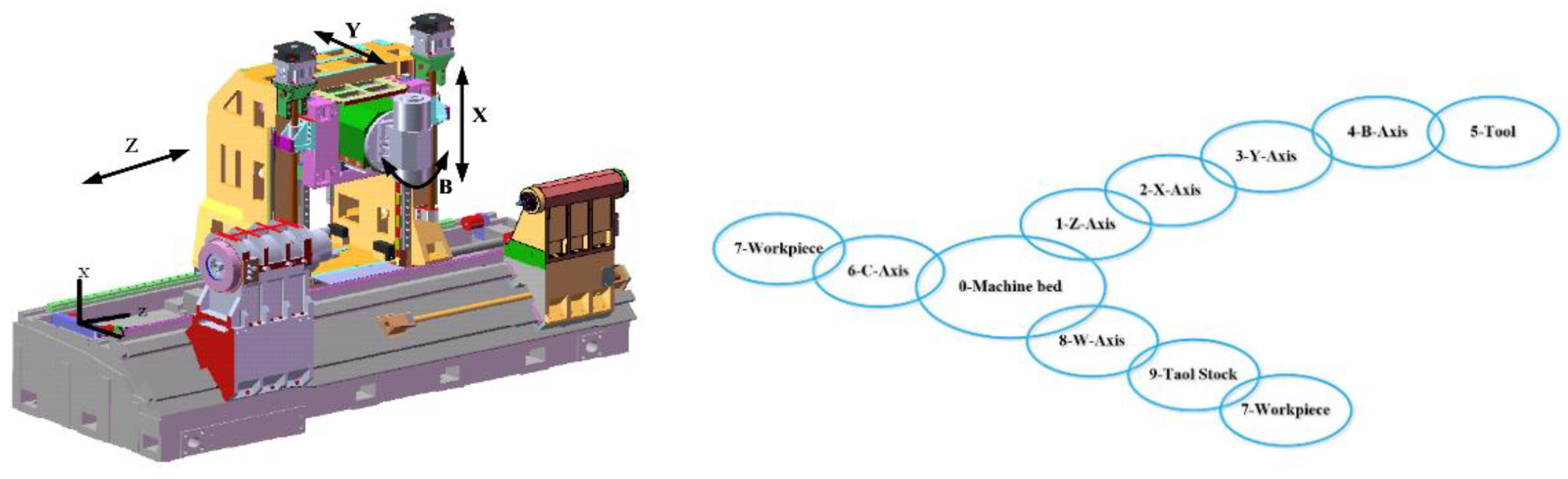
Turn-Milling combined NC machine tool, compared to conventional machining tools, generally have at least three parallel axes and two rotary axes. These multi-axis machine tools change the directional vector of the tool during motion due to the presence of the rotary axes. In addition, the specific structure of the machine tool determines the kinematic relationship between the axes and the obverse and inverse solutions, but the different combinations of parallel axes and rotary axes and the sequence of combinations lead to a variety of configurations of multi-axis machines. Therefore, it is necessary to build geometric error models for machining tools and analyze their tool attitude changes to improve the effectiveness. At the same time, the sensitivity of each geometric error source will provide the weights for the geometric accuracy allocation. This method is less costly than the traditional geometric accuracy allocation, which not only has significant economic value, but also greatly extends the service life of the existing machine tools.
For machine centers, the actual errors and the error compensation values are a pair of “symmetry” data sets which are connected by the movement of machine tools. Through the establishment of error model and sensitivity analysis, the main influencing factors in the symmetric data set can be found. In this work, considering special characteristics of the structure and working mode of the Turn-Milling combined machine tool, its topological structure is described, and 45 geometric error terms are analyzed and determined. Moreover, the ideal and real kinematic models are established, and the geometric error models are derived with the unity coordinate transformation and multibody system theory. Based on the interval theory, the sensitivity of each geometric error source to its spatial error is analyzed. In practical applications, according to the actual error detecting results when the machine running, the key error terms that cause machining errors can be calculated through the proposed error model, and these errors can be compensated in advance by the CNC system. As a new type of machine tool, this work provides an effective method to improve the machining accuracy.
3. Geometric Error Modeling Methods
Firstly, it is necessary to build a kinematic model to establish the kinematic relationship, considering the initial position of each axis and the position changes caused by the movement, between the tool coordinate system and the workpiece coordinate system according to the kinematic chain. Based on low-order body array of actual structure of a CNC machine according to MBS, homogeneous coordinate transformation matrix is used to calculate the position of the cutting point of the tool and the attitude of the tool axis in the workpiece coordinate system. Combined with constraints of the forming motion, the geometric error model can be built, deriving the motion position error of the spatial point and the motion attitude error of the spatial vector.
The kinematic model establishes the relationship between the tool and the workpiece, and the model is also the basis for kinematic obverse and inverse solutions, tool position analysis, and CNC instructions. However, the existence of relative static and motion errors between the axes leads to cumulative errors during actual motion, which have an impact on the theoretical tool path and machining accuracy.
3.1. Analysis of Ideal Kinematics Model of Turn-Milling Combined NC Machine Tool
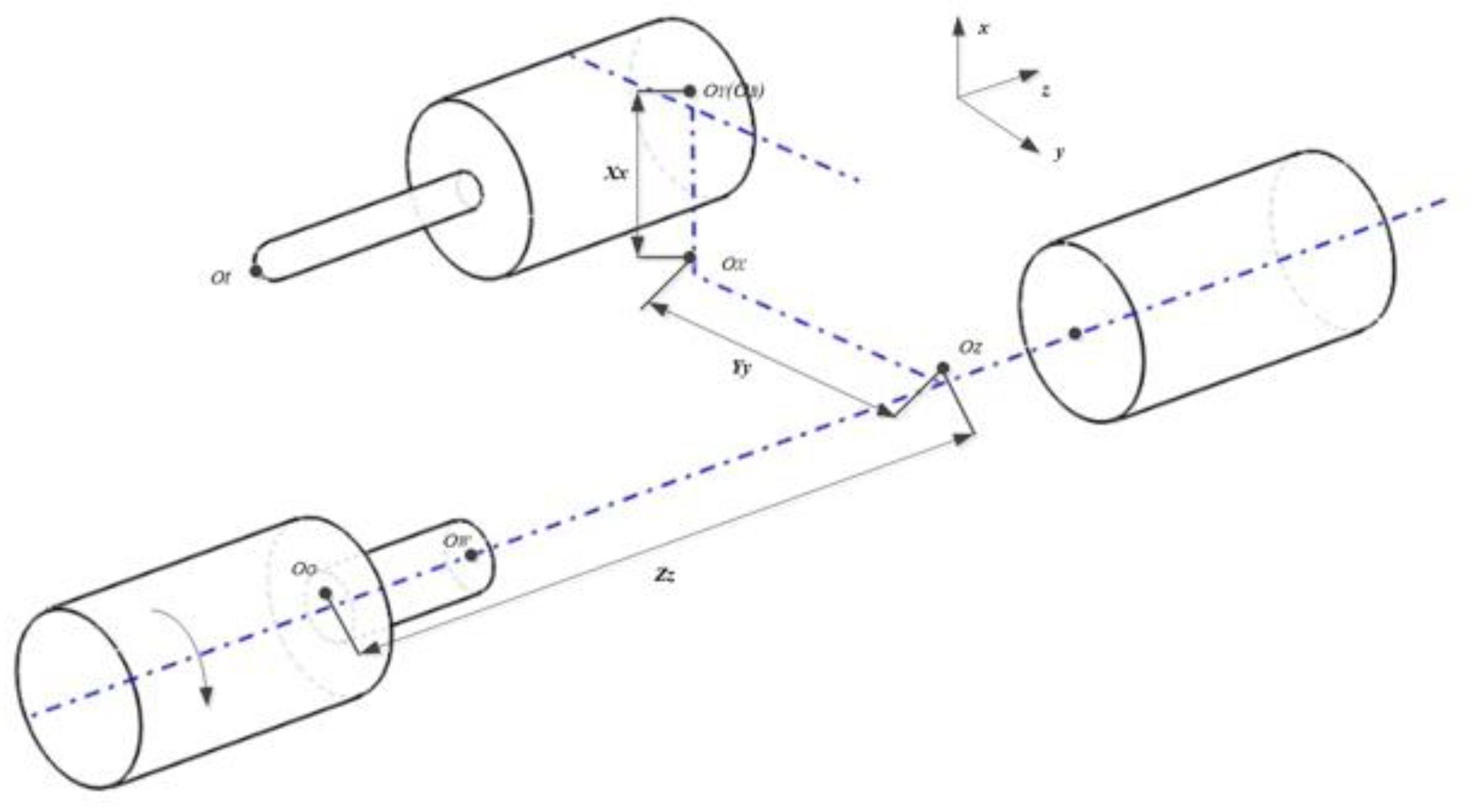
The position relationship between machine tool coordinate system, workpiece coordinate system, and each moving body coordinate system of should first be determined. The machine bed coordinate system
is located at the fixed position of the machine tool and used to determine the reference relationship between workpiece and machine tool, its direction is the same as the theoretical direction of the
X-,
Y-, and
Z-axes. The workpiece coordinate system
is the same as the programming coordinate system used in CAM. When the workpiece mounted to the machine, the deviation relationship between the workpiece and the machine coordinate system can be determined. The origin of the tool coordinate system
is the position of the center point of the tool; the position of these three coordinate systems in space is shown in
Figure 2.
As shown in
Figure 2, there are two kinematic chains in this Turn-Milling Combined NC machine tool.
The first chain: workpiece—C-axis—machine bed—Z-axis—Y-axis—X-axis—spindle—tool.
The second chain: workpiece—tailstock—W-axis—machine bed—Z-axis—X-axis—Y-axis—spindle—tool.
Using the bed as a boundary, the first kinematic chain is divided into a workpiece chain and a tool chain.
Workpiece chain: machine bed—C-axis—workpiece.
Tool chain: machine bed—Z-axis—X-axis—Y-axis—B-axis—tool.
To facilitate kinematic modeling, the coordinate system of each rigid body on the workpiece chain is set at , which is the intersection of the chuck endface and the rotary axis. The Z-axis coordinate system on the tool chain is established at distance from Z axis, the X-axis coordinate system is established at distance from Z-axis, and the Y-axis coordinate system and the tool coordinate system are established at the intersection of the tool axis and the B-axis. All coordinate system orientations are the same as .
3.2. Analysis of Actual Kinematics Model of Turn-Milling Combined NC Machine Tool
Firstly, move the distance of
x,
y,
z along the coordinate axis, then rotate the axis of rotation around the
X- Y-and
Z-axis by angle
A, B and
C successively, the transformation matrix
between the two coordinate systems can be obtained as Equation (1). Homogeneous coordinate transformations achieve the representation of points in different coordinate systems, and the order of translation transformation does not affect the coordinates after the movement of the composite transformation, but the change order of rotation transformation will influence the coordinates.
Since the errors are very small, the Taylor expansion of
and
can be replaced after neglecting the second and higher order terms, expressed as,
3.2.1. The Actual Kinematics Model in Milling Mode
The actual motion in space can be seen as adding an error motion to the theoretical motion. Therefore, the actual motion transformation between adjacent bodies
a and
b can be expressed as the actual coordinate transformation matrix
between
a and
b.
In the actual turn-milling process, the motion error of each axis as well as the spatial geometric error between the axes always exists. Each geometric error is defined in
Table 2, according to which the feature matrix is obtained, as shown in
Table 3.
The actual position vector
of the milling mode in the workpiece coordinate system, according to the transmission chain, can be solved as,
Since the motion of the linear axis does not change the orientation vector of the tool for the linear axis, and therefore only the effect of the position-independent error of the linear axis and the position-dependent error on the tool attitude is considered, the actual orientation vector
of the milling mode of the tool in the workpiece coordinate system can be written as,
The position vector and the direction vector of the tooltip point can be obtained in the workpiece coordinate system by Equations (6) and (7).
3.2.2. The Actual Kinematics Model in Turning Mode
Based on the theoretical model of kinematics in the turning mode and the error-transformation matrix, the actual kinematics model with geometric errors can be solved as,
In this mode, since the orientation vector of the tool does not change, only the actual position vector needs to be analyzed.
3.3. Geometry Error Modeling of Turn-Milling Combined NC Machine Tool
With the low-order body analysis, the corresponding feature matrices are built according to of each adjacent body features in each error branch, which are represented by the main feature symbols and auxiliary feature symbols, and then the corresponding standard feature matrices are found according to the feature symbols of adjacent body.
The position vector error
and the direction vector error
can be written as,
3.3.1. Geometry Error Modeling in Milling Mode
According to Equation (9), the kinematic error
in the milling mode can be written as,
3.3.2. Translation Axis Geometric Error Model
Parallel unit is an important component in the multi-axis CNC machine tool system, and the geometric error of the parallel unit accounts for a large proportion of the machine tool geometric error. As a specialized research, the parallel system geometric spatial error model should be built. This error model in the total geometric error modeling is easy to obtain.
Assuming that the rotary feed unit and spindle are fixed,
can be written as,
Ignoring second-order and higher-order items,
can be represented as,
4. Geometric Precision Error Analysis
Geometric error compensation can improve the machining accuracy to a certain extent, but when compensating each geometric error, there are problems such as heavy workload and poor compensation effect. To avoid the blindness of the error compensation, the sensitivity analysis of the geometric error should be carried out. The sensitivity coefficient of the error term can quantify the influence weight of each error term. Based on the sensitivity analysis result, the error terms that have a significant impact on accuracy can be identified. Targeted compensation and correction of important sensitive error terms can effectively improve machining accuracy.
4.1. Analysis of the Interval Sensitivity of Each Axis to Geometric Errors
The sensitivity
of position error source
to the spatial error component
can be defined directly as,
In Equation (14), is the interval expansion factor of the angular error source on the spatial error component . When the instrument measurement axis does not coincide exactly with the actual motion axis, an error caused by the axis angle will be generated during movement of the parts, known as Abbe error. Therefore, for the angle error source, the interval dilation factor cannot be used directly as sensitivity due to the existence of Abbe error.
Based on the above considerations, the sensitivity
of the angular error source
to the spatial error component
is,
In Equation (15), is the interval expansion factor of the angular error source for the spatial error component when the X-, Y-, and Z-axes are located at the origin and the tool length is 0.
According to the actual structure of the machine, the values of each body coordinate system in the basic coordinate system are:
.
are related to the actual workpiece coordinate system position of the part and the tool length. Substituting the structural parameter values into the spatial error Equation (13) for the Turn-milling combined NC machine tool, the simplified error model is obtained as,
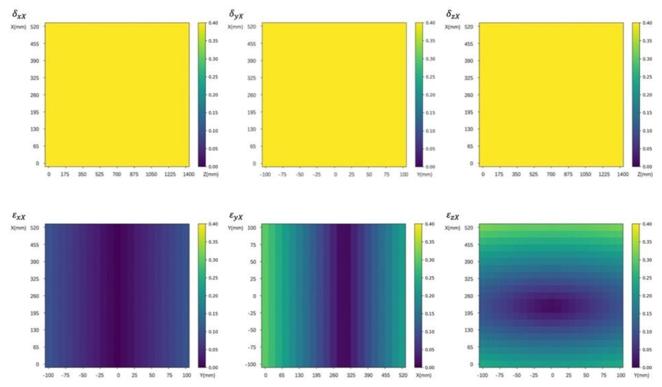
4.1.1. Interval Sensitivity Analysis of X-Axis Geometric Error to Spatial Error
To describe the sensitivity coefficients
and
more clearly, the statistics and analysis of the data are carried out with the matplotlib module of Python. The sensitivity coefficients of the
X-axis geometric errors are shown in
Figure 3.
The six geometric errors, on X-axis are sequentially analyzed. have the same effect on the spatial error; and their sensitivity does not change with the position movement, and the sensitivity to is always 1. The sensitivity of to terms does not exceed 0.1, and increases with the increase of Y coordinate. The sensitivity of to spatial error decreases first and then increases with the increase of the X coordinate, and the maximum value does not exceed 0.35. The sensitivity of to spatial error first decreases and then increases with the increase of X coordinate, which increases with the increase of Y coordinate, and the sensitivity changing along X-axis has a larger range.
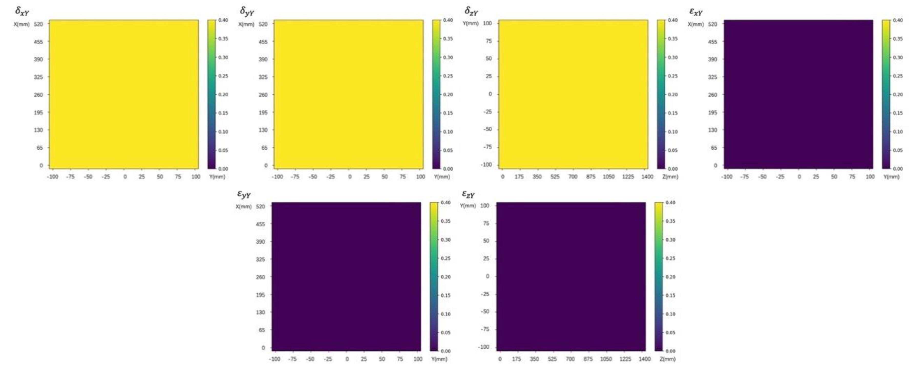
4.1.2. Interval Sensitivity Analysis of Y-Axis Geometric Error to Spatial Error
The sensitivity analysis on the 6 geometric errors
on
Y-axis at above position points can be drawn from
Figure 4. Three errors
have the same effect on the spatial error. Their sensitivity does not change with the movement of the
X-axis,
Y-axis and
Z-axis, and the sensitivity to the ∆r is always 1. Three items
, have no effect on errors in Δ
X, Δ
Y, and Δ
Z directions, can be ignored.
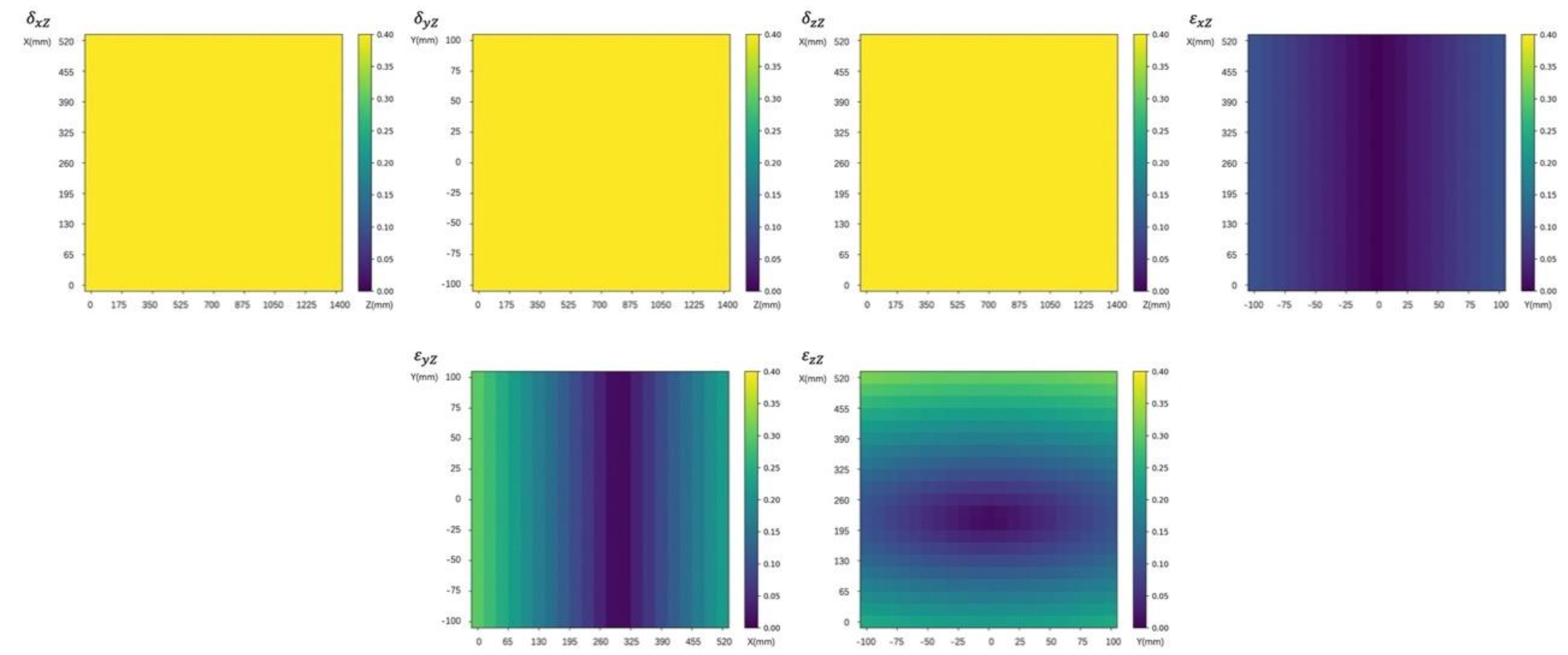
4.1.3. Interval Sensitivity Analysis of Z-axis Geometric Error to Spatial Error
The sensitivity of the six geometric errors
on
Z-axis at above position points can be drawn from
Figure 5.
The influence of on the spatial error is the same as the position error of X-axis and Y-axis. Its sensitivity does not change with the movement of X-axis, Y-axis and Z-axis, and the sensitivity to ∆r point is always 1.
The sensitivity of shows an upward trend as Y coordinate moves away from the origin, but the maximum value is only 0.1. The sensitivity of increases first and then decreases with the increase of X coordinate, so the error sensitivity at both ends of X-axis is the highest, reaching about 0.3. The sensitivity of changes with the movement of both X-axis and Y-axis.
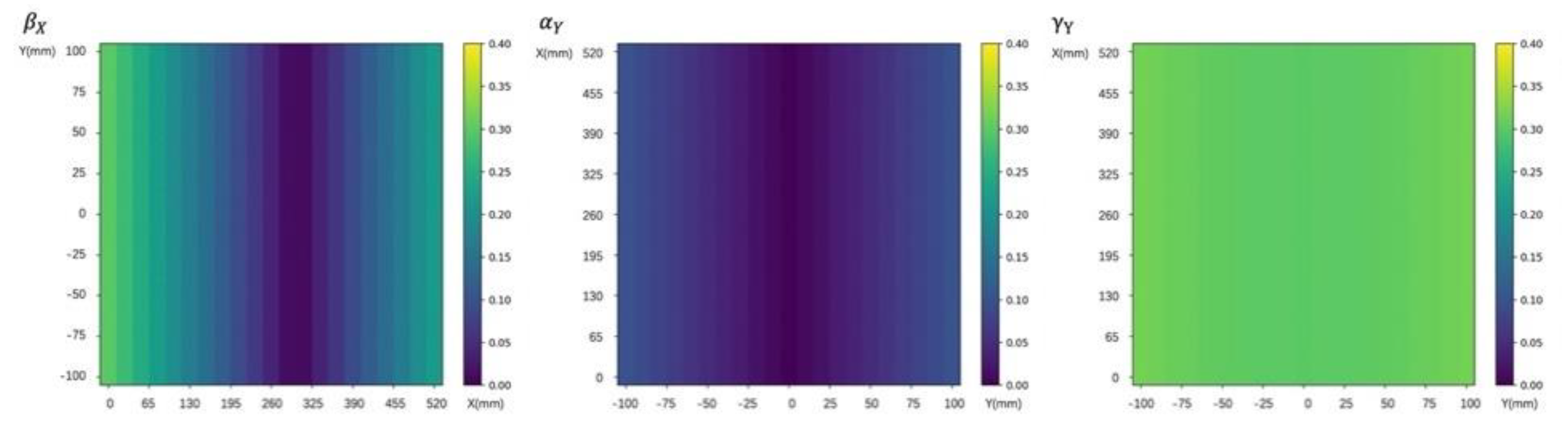
4.1.4. Interval Sensitivity Analysis of Perpendicularity Errors to Spatial Errors
As shown in
Figure 6, three squareness errors
all affect the spatial error. The sensitivity of
error is relatively largest, and it changes slightly with the movement of
Y-axis, basically stable at about 0.3. The sensitivity of
is relatively small and has been stable below 0.1. The
sensitivity changes with the movement of
X-axis, and has the largest changing range.
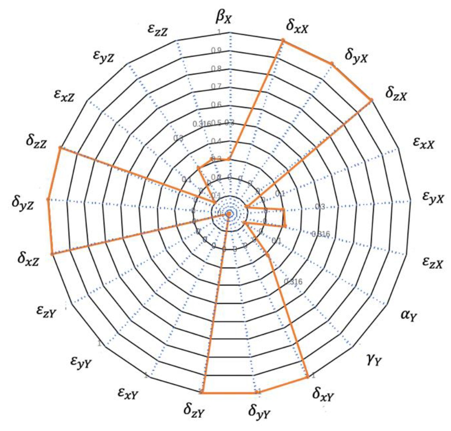
4.2. Global Maximum Interval Sensitivity Analysis to Spatial Error of Geometric Error Sources
The global maximum interval sensitivity can guide the accuracy design in the actual manufacturing assembly process. The global maximum interval sensitivity
of the angular error source
to the spatial error component
is expressed as,
The global maximum interval sensitivity of the geometric error source to spatial error
is expressed as,
The maximum interval sensitivity
can be used directly as the sensitivity of the machine tool accuracy design index. Based on the sensitivity design, by assigning a tolerance interval to each error source, all geometric error sources of the machine tool can meet the design requirements in space. By Equation (18), each geometric error source to the spatial error of the global maximum interval sensitivity can be calculated, as shown in
Figure 7.
Three angular errors result from the forward and backward movement of the slide ram have no effect on the spatial error, but the other geometric error sources have varying degrees of influence on the spatial error. The sensitivity of each position error, the axis positioning error and the straightness error to the global maximum interval of the spatial error, is the same value 1. For other error terms, the roll error of Z axis, the yaw error of X-axis, and the squareness error between X-axis and Z-axis have the greatest sensitivity to the global maximum interval. The pitch error of X-axis and Y-axis and the squareness error between X-axis and Y-axis have the second highest sensitivity. The yaw error of X-axis, the pitch error of Z-axis and the squareness error between Y-axis and Z-axis.
5. AN Experimental Study
In above analysis, proposed spatial geometric error model helps to describe the relationship between each geometric error term and the final machining error. The sensitivity analysis can effectively reflect influence degree of each error term on the final error under different machining conditions. With results of sensitivity analysis, can obtain the sensitive error term with great influence on the machine accuracy can be given. Based on the above work, this section carries out an experimental study on the sensitivity model of a Turn-milling combined NC machine tool. Without considering the comprehensiveness of errors, the experimental study is limited as follows: the machine components are considered as rigid bodies; and the machine parts have similar manufacturing accuracy are. The errors value can reflect the influence degree on the machine tool accuracy, namely the geometric error sensitivity of machining tool.
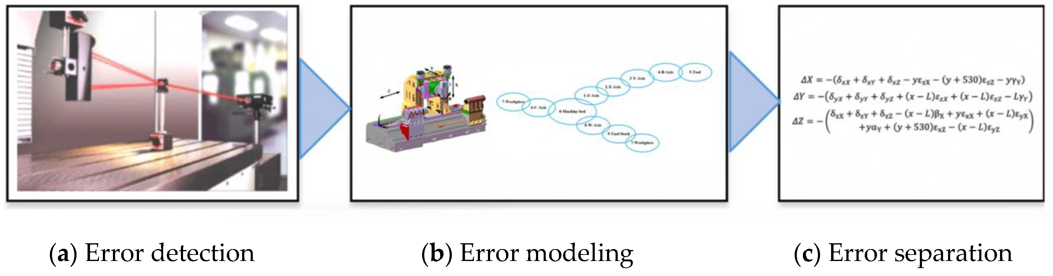
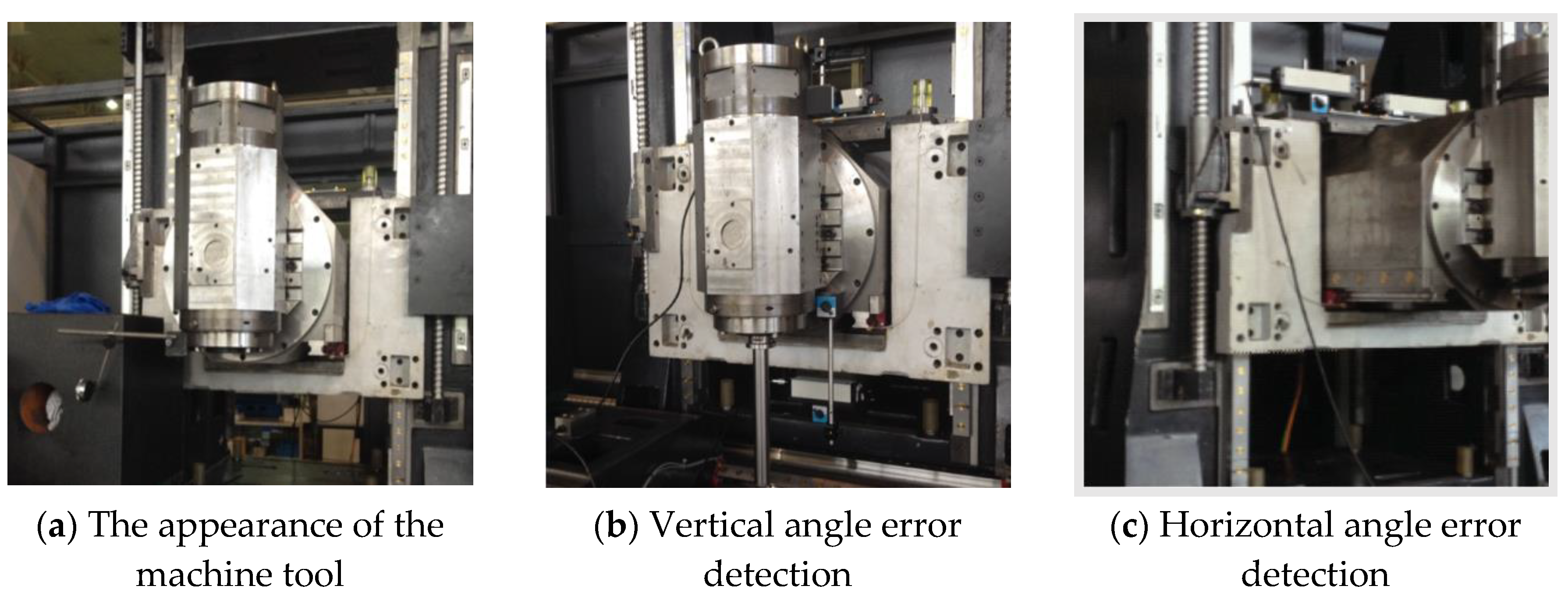
Taking
Y-axis of a Turn-milling combined NC machine tool as an example, the experimental procedure of geometric error sensitivity model verification is shown in
Figure 8. Firstly, the various error terms of the combined geometric accuracy of turning and milling, shown in
Figure 9, are measured. Then, the typical error modeling, error separation method and experimental fitting method are used to separate the error terms of
Y-axis, and values of all error terms are analyzed comparatively to verify the error sensitivity model established in this paper.
With the geometric error sensitivity model of the Turn-milling combined NC machine tool, the typical error separation and experimental fitting methods are used to decompose various geometric errors. The decomposition results are shown in
Table 4. The error values of
are 1.0092, 4.2666 and 36.712, respectively.
are 6.91 × 10
−5, 0.04744, and 9.09 × 10
−7, respectively, which are at least 2 orders of magnitude smaller than
. Among them, the value of
is larger due to the error caused by the weight of
Y-axis and B axis. And the reason for a larger value of
is synchronization error of
Y-axis. The experimental results is close to the sensitivity analysis results of the geometric error mentioned above. That is, the positioning error and linearity error of
Y-axis are highly sensitive, while the sensitivity of yaw error, pitch error, and roll error is low. The sensitivity analysis results of the turning-milling compound geometric error is consistent with the experimental error decomposition results, demonstrating the effectiveness of the sensitivity analysis method.
6. Conclusions and Discussion
6.1. Discussion
With the increasing application of multi-axis simultaneous machining machines, subsequent work can gradually extend the methodological basis of this Turn-Milling compounding research to different multi-axis machines. This paper establishes a mathematical model of the geometric error for the Turn-Milling combining and error compensation through the results of sensitivity analysis. The method is an efficient, economical, and practical way to improve the machining accuracy of machine tools. From the current state of development, there are still some aspects that need to be further studied and solved. Most of the existing geometric error model research is based on the case of no-load operation, when the Turn-Milling compound error modeling, the error model can increase in the actual machining process of cutting force, tool wear, and vibration and other factors. The geometric error, thermal error, and cutting force error of different parts and different machining speeds may vary greatly. Therefore, a comprehensive error model more in line with the actual machining conditions should be established in subsequent research. The accuracy and robustness of the error model must be considered to improve the machining accuracy.
The interval sensitivity analysis provides geometric accuracy allocation weights for the next study on the optimal allocation of geometric accuracy, but it needs to establish a dynamic feedback mechanism with the actual manufacturing and assembly process. In the process of this research, the analysis is only based on the spatial error accuracy index of machine tool. Subsequently, the dynamic changes of geometric errors in the actual manufacturing and assembly process should be fully considered to avoid too loose or too tight tolerances caused by some geometric error sources, which can increase the unnecessary assembly time and cost.
6.2. Conclusions
Turn-milling combined NC machine tool generally have at least three parallel axes and two rotary axes. With the existence of the rotary axes, the directional vector of the tool is also changed during the movement, and the trajectory of the tool cannot be imagined visually under the machine coordinate system. Therefore, the topological relations of the machine tool were established with the MBS. Furthermore, the position transformation matrices, the position error transformation matrices, the motion transformation matrices, and the motion error transformation matrices under ideal and actual motion conditions were deduced with the homogeneous coordinate transformations. Through the multiplication of the characteristic matrix, the spatial error model of the whole machine with five-axis linkage in milling mode and three-axis linkage in turning mode is obtained.
In previous, the error sensitivity in a particular state of the machine was usually analyzed, and the error sensitivity during machine movement was only analyzed qualitatively. In this paper, the error sensitivity in different positions of the machine tool is analyzed more precisely. Geometric error sensitivity coefficients are calculated for the spatial geometric error model of the machine tool. With interval theory, its error models along X, Y, and Z directions are built using an interval sensitivity analysis. Based on the results of the sensitivity analysis, it can be shown that the errors ; are important sensitive errors that have a significant impact on the machining accuracy. And the tolerance ranges related to the above factors should be strictly controlled in the optimization of machine geometry accuracy. The tolerance range can be relaxed to a larger range for geometric error sources with small global maximum interval sensitivity, such as . It is important to pay attention to the error terms that have a significant impact on machining accuracy and give priority to ensuring their accuracy in the machine design, manufacturing, assembly, and other stages.
The geometric error sensitivity analysis method proposed in this paper can accurately evaluate the influence weights of each error term on the machining accuracy of Turn-Milling Combined NC machine tool, and accurately identify the important sensitive error terms that have a great influence on the machining accuracy from many error terms. Geometric error sensitivity analysis can provide a theoretical basis for geometric error index distribution and geometric error accuracy optimization for Turn-Milling machine centers in precision design process, manufacturing, assembly, and debugging. At the same time, it can clarify the priority of the error compensation order in the error compensation stage.


