Article

Method of Calculating the Vertical Displacement and Additional Stress of Existing Tunnels under the Influence of Grouting Rings of New Tunnels

1
Department of Civil Engineering, Zhejiang University City College, Hangzhou 310015, China
2
School of Civil Engineering and Architecture, Anhui University of Science and Technology, Huainan 232001, China
*
Author to whom correspondence should be addressed.
Symmetry 2020, 12(10), 1623; https://doi.org/10.3390/sym12101623
Submission received: 11 September 2020 / Revised: 27 September 2020 / Accepted: 29 September 2020 / Published: 1 October 2020

Abstract

:
In order to reduce the disturbance to adjacent tunnels caused by tunnel crossing, the existing tunnels are often reinforced by setting grouting rings along the pipe piece ring. In this context, the volume expansion of the grouted soil has to be taken into account, and a mechanical model of the volume expansion of the grouting rings is proposed here to study the effect of the grouting rings of new tunnels on the additional stress on the existing tunnels as well as their vertical displacement. The additional stresses on and the vertical displacement of the axis of the existing tunnels caused by the expansion of the grouting rings were deduced based on the stochastic medium theory. The influences of various volumetric expansion rates (Q) of the grouting rings, different lengths of the grouting rings, and different tunnel crossing angles on the settlement of and the additional stress on the existing tunnels were studied. The results demonstrate that the grouting rings can effectively reduce the impacts of the additional stress and the settlement deformation on the existing tunnels. The results of the tunnel settlement obtained from the calculation method proposed in this paper are in good agreement with the measured engineering data.

1. Introduction

With the development of urban subway construction, there are an increasing number of subway lines in a limited shallow ground space, which has resulted in more new shield tunnels crossing the existing tunnels in close proximity [1,2]. Close crossing of the shield tunnels will lead to the deformation of the surrounding soil and the redistribution of stress on the soil, which affects the safety of the existing tunnels [3]. In actual engineering applications, certain protective measures need to be taken to reduce the impact of the disturbance on the existing tunnels. Thus, it is necessary to research into the deformation law and protection measures of the existing tunnels under close crossing of the tunneling shields.
For the problem of shield tunneling through existing tunnels at close range, the current main research methods include numerical simulation [4,5], measured data analysis [6,7], and theoretical analysis [8,9]. There are many types of protection measures, one of which is to use grouting holes to grout behind the pipe wall and form a certain angle of grouting rings [10,11]. The process of grouting to form the grouting ring involves various modes of action such as infiltration, compaction, and splitting of the soil grout, and the mechanism of its influence is complex. In this regard, Au et al. [12] pointed out that the influence of grouting on the surrounding soil can be simulated by the volume expansion of the soil in the grouting area. Based on this idea, Zhang Dongmei et al. [13] employed numerical simulation methods to study the transverse deformation laws of tunnels caused by lateral grouting and verified the rationality of the simplified treatment method of simulating grouting through volume expansion. Therefore, the influence of the grouting rings of the new tunnels can be simulated by the volume expansion of the surrounding soil. However, there is no theoretical calculation method for analyzing the effect of the grouting rings behind the wall of the new tunnels, so it is necessary to build a mechanical model and propose a method so as to evaluate the effect of the grouting rings on the reduction of crossing disturbance.
This paper simulated the effect of grouting by the volume expansion of the soil in the grouting area. According to the characteristics of the grouting rings of the new tunnels, a volume expansion model of the grouting rings was established. Further, based on the stochastic medium theory and the research results of Qi Jingjing et al. [14], the calculation formulas for the vertical displacement of and the additional stress on the surrounding soil caused by the expansion of the grouting rings were deduced; also, the additional stress on the axis of the existing tunnels under the joint influence of the tunnel excavation and the grouting rings was calculated. The vertical displacement of the existing tunnels was also calculated using the coordinated deformation model of the shear staggered platform and rigid body rotation [15]. Moreover, the additional stress on and the vertical settlement of the axis of the existing tunnels before and after installing the grouting rings in the new tunnels were compared and analyzed. Finally, the effects of various volume expansion rates of the grouting rings, different lengths of the grouting rings, and various tunnel crossing angles on the additional stress on and the vertical displacement of the existing tunnels were investigated.

2. Proposed Calculation Method

2.1. Method of Solving Additional Stress on Existing Tunnels at Any Angle

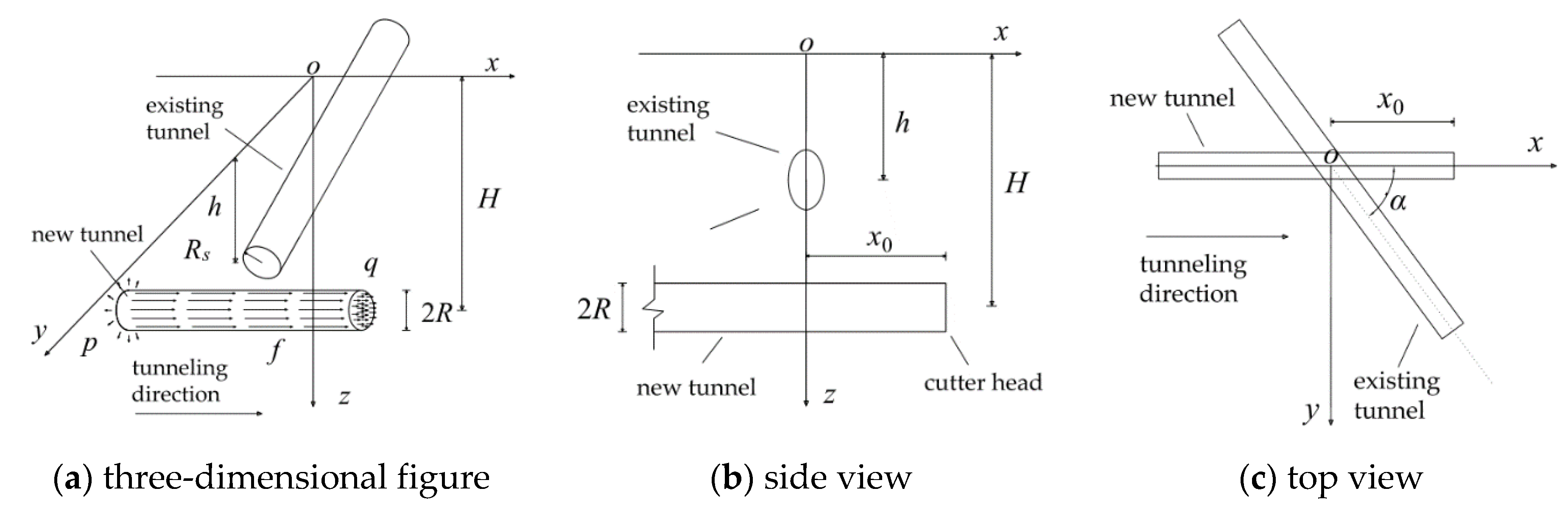
2.1.1. Establishment of a Mechanical Model

As shown in Figure 1a–c, the central axis of the new tunnel is parallel to the x-axis and passes through the existing tunnel at an angle of α ( 0 < α 90 ) . Also, the intersection of the two tunnel axes is located at point o. The relevant parameters of the new tunnel are the buried depth of the axis (H), the excavation surface position (x0), and the radius of the tunnel (R). The influencing factors involved in the excavation process include the additional thrust (q) of the cutter head, the friction resistance (f) of the shield shell, the additional grouting force (p), and soil loss characteristics. The relevant parameters of the existing tunnel are the buried depth of the axis (h) and the radius of the tunnel (Rs). In this work, we considered the excavation surface position and the tunnel crossing angle (α) to be variable and improved the deficiencies of the calculation method presented in ref [16] to make our calculation method more widely applicable.

2.1.2. Solution for Additional Stress Caused by Shield Tunneling

In the established model, the directions of loads q and f are along the positive direction of the x- axis, and load p is along the radial direction of the shield tail. In order to facilitate the calculation, load p is decomposed into load component p1 along the z-axis and load component p2 along the y- axis.
Based on the Mindlin solution [17], if any point ( x 1 , y 1 , z 1 ) below the ground acts on force σx along the x-axis, force σy along the y-axis, or force σz along the z-axis, stress components σx-z, σy-z, and σz-z of any point ( x , y , z ) in the soil in the vertical z direction can be defined as:
σ x-z = σ x ( x x 1 ) 8 π ( 1 μ ) { 1 + 2 μ M 3 + 1 2 μ N 3 + 3 ( z z 1 ) 2 M 5 + 3 ( 3 4 μ ) ( z + z 1 ) 2 N 5 6 z 1 N 5 [ z 1 + ( 1 2 μ ) ( z + z 1 ) + 5 z ( z + z 1 ) 2 N 2 ] }
σ y-z = σ y ( y y 1 ) 8 π ( 1 μ ) [ 1 + 2 μ M 3 + 1 2 μ N 3 + 3 ( z z 1 ) 2 M 5 + 3 ( 3 4 μ ) ( z + z 1 ) 2 N 5 6 z 1 N 5 ( z 1 + ( 1 2 μ ) ( z + z 1 ) + 5 z ( z + z 1 ) 2 N 2 ) ]
σ z-z = σ z 8 π ( 1 μ ) [ ( 1 2 μ ) ( z z 1 ) M 3 ( 1 2 μ ) ( z z 1 ) N 3 + 3 ( 3 4 μ ) z ( z + z 1 ) 2 3 z 1 ( z + z 1 ) ( 5 z z 1 ) N 5 + 30 z 1 z ( z + z 1 ) 3 N 7 + 3 ( z z 1 ) 3 M 5 ]
where M = ( x x 1 ) 2 + ( y y 1 ) 2 + ( z z 1 ) 2 and N = ( x x 1 ) 2 + ( y y 1 ) 2 + ( z + z 1 ) 2 ; μ is the Poisson’s ratio of soil.
Based on Equations (1)–(3) and referring to ref [16], stress components σz-q, σz-f, σz-p1, and σz-p2 can be obtained for stresses q, f, p1, and p2 at any point ( x , y , z ) along the z-axis. Due to the limited space in this paper, the specific integration and derivation process is not repeated.
In order to obtain the additional stress value along the axis of the existing tunnel, it is necessary to arrange the derivative points ( x , y , z ) along the axis of the existing tunnel, so the coordinates of the derivative points should satisfy:
{ y = x tan α z = h
To calculate the additional stress component σz-s on the axis of the existing tunnel caused by soil loss, this paper refers to the method described in ref [18], and we obtain:
U z-s = B η ( x ) R 2 2 { H z y 2 + ( H z ) 2 + H + z y 2 + ( H + z ) 2 2 z [ y 2 ( H + z ) 2 ] [ y 2 + ( H + z ) 2 ] 2 } exp [ y 2 ln λ ( H + R ) 2 + z 2 ( ln λ ln δ ) ( H + d ) 2 ]
σ z-s = k U z-s
where
  • B = 4 H [ H + d ( H + d ) 2 η ( x ) ( R + d ) 2 ] R η ( x ) ( R + d ) ,
  • δ = 1 2 1 π arcsin [ 2 d R ( 1 + 1 η ( x ) ) ] ,
  • λ = 1 4 2 ( 1 1 η ( x ) ) π η ( x ) [ arcsin ( d R 1 η ( x ) ) + 1 ( d R 1 η ( x ) ) 2 1 ] ,
  • η ( x ) = η s 2 [ 1 x x 2 + H 2 ] .
where ηs is the percentage of soil loss in the tunnel excavation, and η(x) represents the soil loss rate as a function of the x-axis; B, δ, and λ are intermediate calculation variables; d stands for the distance from the focal point of the soil movement to the tunnel center, and U z-s is the vertical displacement of soil at point ( x , y , z ) ; k is the foundation bed coefficient.
By superposing stress components σ z-q , σ z-f , σ z-p1 , σ z-p2 , and σ z-s , the total vertical stress of the tunnel excavation (σz-k) can be expressed in:
σ z-k = σ z-q + σ z-f + σ z- p 1 + σ z- p 2 + σ z-s

2.2. Analysis of the Principle of Circumferential Grouting and Its Influence on the Surroundings

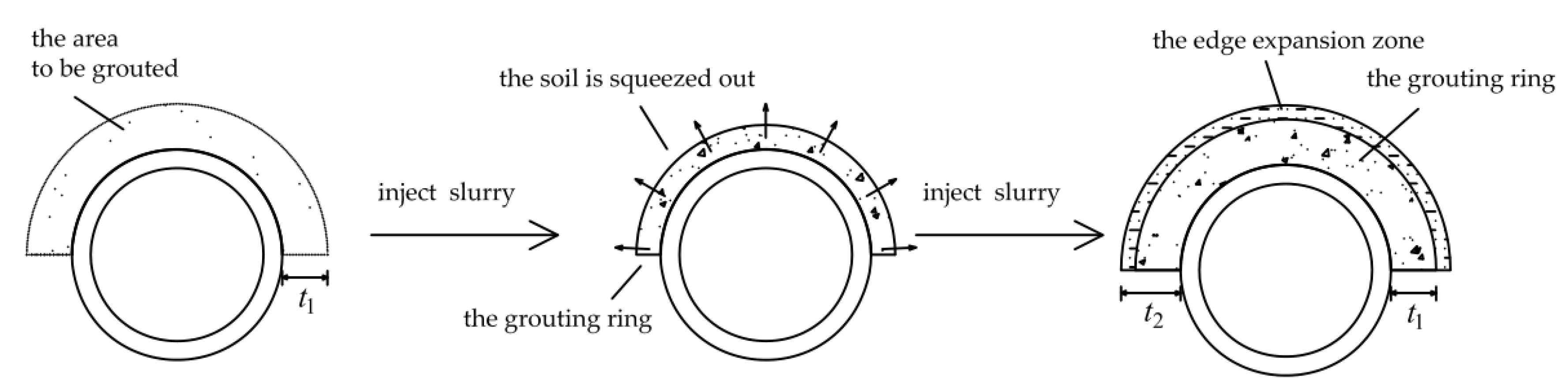
2.2.1. Analysis of the Principle of Circumferential Grouting

After the shield passes through the existing tunnel, a steel pipe is drilled through the grouting hole on the already installed segment to perform post-wall grouting and thus forms a layer of grouting ring on the outer wall of the new tunnel, which belongs to secondary compensation grouting technology. There are various grouting ring angles, mainly 120, 180, 270, and 360°, and this work introduced the grouting ring angle of 180° as an example.
Grouting reinforcement in the soil mainly uses slurry to squeeze the soil and fill the soil voids through infiltration, compaction, and splitting so as to improve the self-stabilization capacity and deformation resistance of the soil. As shown in Figure 2, the original thickness of the area to be grouted is t1. Due to the injection of a large amount of slurry, the voids in the original native body are further filled and compacted. With the continuous increase in the grouting volume, part of the soil in the area to be grouted is squeezed out in the radial direction due to extrusion after the soil voids in the grouting area are filled. When the grouting ring is solidified and stabilized, the extruded soil adheres to the surface of the grouting ring to form an edge expansion zone, and the grouting ring forms grouting and solidification with a thickness of t2. In summary, the influence of the grouting behind the wall on the external soil deformation can be reflected in the volume growth of the grouting affected zone. The volume of the space to be grouted before grouting is V1, and it increases to V2 after grouting; thus, the volume expansion rate (Q) can be expressed through:
Q = V 2 V 1 = 1 2 π ( R + t 2 ) 2 1 2 π ( R + t 1 ) 2 1 2 π ( R + t 1 ) 2 1 2 π R 2 × 100 % = ( R + t 2 ) 2 ( R + t 1 ) 2 ( R + t 1 ) 2 R 2 × 100 %
According to the study of Au et al. [12], the volume expansion rate (Q) is related to the volume of injected grout (Vinj) and the efficiency of grouting (ξ), which can be expressed as:
ξ = V 2 V 1 V inj = Q V 1 V inj
It can be further transformed into:
Q = ξ V inj V 1
where the efficiency of grouting (ξ) is related to construction parameters such as soil properties and grouting pressure. This can be obtained in actual projects according to engineering experience, experimental tests, or other methods. If soil deformation during grouting occurs in undrained conditions, ξ = 100%; the volume of the space to be grouted (V1) can be reasonably designed according to the construction conditions and equipment. The determination of the volume of injected grout (Vinj) only needs to substitute the efficiency of grouting (ξ), the optimal volume expansion rate, and the volume of the space to be grouted (V1) into Equation (10); the volume expansion rate (Q) is a parameter that reflects the impact of the grouting ring on the surrounding environment, and we provide a method to estimate its reasonable range of values in the following sections.

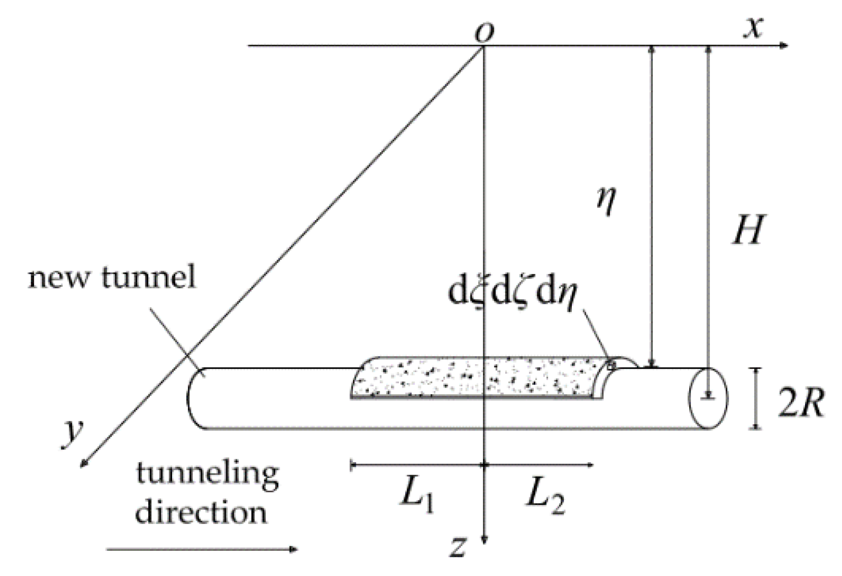
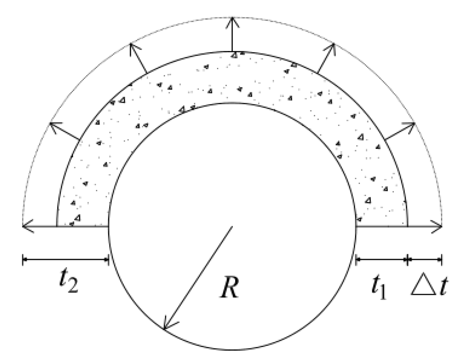
2.2.2. Establishment of the Grouting Ring Expansion Model and Calculation of Its Influence on the Surroundings

In order to study the impact of the circular grouting of the new tunnel on the upper existing tunnel, the work in this section is based on the stochastic medium theory and the research results of Qi Jingjing et al. [14]. The volume of any calculation unit in the soil is d ξ d ζ d η , and its buried depth is equal to η. The displacement of the soil at any point ( x , y , z ) in the upper part caused by the complete collapse of the excavation unit in the vertical direction is given by:
d U-z = 1 r 2 ( z ) exp [ π r 2 ( z ) ( x 2 + y 2 ) ] d ξ d ζ d η
where r ( z ) is the influence radius in the z direction, r ( z ) = η z tan β z , tan β z = h z 2 π i z , h represents the calculated buried depth, iz stands for the width coefficient of the soil settlement trough, φ is the friction angle in the soil, i z = i 0 ( 1 z h ) 0.3 , and i0 is the width coefficient of the ground settlement trough, which can be obtained according to the method of Knothe [19], that is, i 0 = h 2 π tan ( 45 φ 2 ) .
As shown in Figure 3 and Figure 4, the current work takes the example of the 180° upper semicircular grouting ring. The total length of the grouting ring (L) is defined as L1 + L2, where L1 and L2 represent the length of the back section and the length of the front section respectively. Also, the buried depth of the axis of the new tunnel and the radius of the new tunnel are represented by H and R respectively. Any calculation unit in the grouting ring is taken as d V = d ξ d ζ d η , and the buried depth of the calculation unit is equal to η; the thickness of the grouting ring is t1. Due to the influence of the grouting, part of the soil in the original grouting zone is extruded to form an edge expansion zone. The thickness of the edge expansion zone is represented by Δt, and the final thickness of the slurry– soil mixture is t2. The volume expansion rate is indicated by Q. Based on the stochastic medium theory and the research results of Qi Jingjing et al. [14], the vertical deformation (Uz-u) of and the additional stress (σz-u) on the surrounding soil caused by the grouting can be obtained by integrating the grouting ring and the edge expansion zone as follows:
U z-u = a 1 b 1 c 1 d 1 e 1 f 1 d U z a 2 b 2 c 2 d 2 e 2 f 2 d U z = a 1 b 1 c 1 d 1 e 1 f 1 { tan 2 β z ( η z ) 2 exp { π tan 2 β z ( η z ) 2 [ ( x ξ ) 2 + ( y ζ ) 2 ] } } d η d ζ d ξ a 2 b 2 c 2 d 2 e 2 f 2 { tan 2 β z ( η z ) 3 exp { π tan 2 β z ( η z ) 2 [ ( x ξ ) 2 + ( y ζ ) 2 ] } } d η d ζ d ξ
σ z-u = k U z-u
where a and b are the lower and upper integral limits of variable ξ (along the x-axis) respectively; c and d are the lower and upper integral limits of variable ζ (along the y-axis) respectively; e and f are the lower and upper integral limits of variable η (along the z-axis) respectively; the subscript 1 indicates that the integration area is the grouting area, and the subscript 2 denotes that the integration area is the grouting area and the edge expansion area. The calculation formula for the upper and lower limits of each integral is defined as: a 1 = L 1 , b 1 = L 2 , c 1 = ( R + t 1 ) , d 1 = R + t 1 , e 1 = H ( R + t 1 ) 2 ζ 2 , f 1 = H + ( R + t 1 ) 2 ζ 2 , a 2 = L 1 , b 2 = L 2 , c 2 = ( R + t 2 ) , d 2 = R + t 2 , e 2 = H ( R + t 2 ) 2 ζ 2 , and f 2 = H + ( R + t 2 ) 2 ζ 2 .

2.3. Calculation of the Vertical Displacement of Existing Tunnels

Based on Equation (7), the total vertical stress (σz) acting on the axis of the existing tunnel after taking into account the influence of the grouting ring is expressed by:
σ z = σ z k + σ z u = σ z q + σ z f + σ z p 1 + σ z p 2 + σ z s + σ z u
Herein, the vertical displacement of the existing tunnel is calculated by the coordinated deformation model of the shear staggered platform and rigid body rotation proposed in ref [15]. This model is based on the energy variation method and is further developed from the shear misalignment model proposed by Zhou Shunhua et al. [20]. The model assumes that the vertical deformation of the tunnel includes segment ring rotation and misalignment deformation, which have been introduced in detail in several works [15,21]. Therefore, this work does not repeat here the derivation process of the formula, and the interested reader is referred to the original text.
The final calculation formula for the vertical displacement (ω) of the existing tunnel is given by:
ω = { T n ( l ) } A T
where T n ( l ) = { 1 , cos π l N D t , cos 2 π l N D t , , cos n π l N D t } , A = ( a 1 , a 2 , a 3 , , a n ) T , a i is the matrix element, N represents the number of affected segments on one side of the existing tunnel, Dt is the ring width of the segment, and l stands for the length variable along the axis of the existing tunnel.

3. Analysis and Reliability Verification of an Engineering Case

3.1. Example Conditions

This work takes the example of the project of a new tunnel underneath an existing two-lane tunnel in Hangzhou, China. As shown in Figure 5, the new tunnel is driven from right to left and passes through the upline of the existing tunnel at an angle of 62° and through the downline of the existing tunnel at an angle of 61°. In order to reduce the effect of the tunnel underpass on the settlement of the existing two-lane tunnels, circular grouting will be carried out within the influence range of the existing line after the shield traverses the existing line, thereby forming a semicircular grouting reinforcement ring on the top of the new tunnel from ring 2021 to ring 2054. The thickness and the total length of the grouting ring are 1.5 and 49.5 m respectively. The new tunnel and the existing tunnel are mainly located in the silt layer. Other relevant parameters are listed in Table 1.

3.2. Theoretical Calculation Results

Figure 6 and Figure 7 show the comparison of the additional stress and the settlement distribution curves of the upline with a grouting ring with those without a grouting ring. These two figures show that, first, the grouting ring can significantly reduce the influence of the additional stress on the existing tunnel. Without the grouting ring, the additional stress on the existing tunnel is normally distributed, and the maximum additional stress is 40.92 kPa, which occurs in the crossing center. After the installation of the grouting ring, the overall additional stress is reduced, and the maximum additional stress in the center decreases to 13.79 kPa. Second, due to the impact of the grouting ring, the additional stress on the existing tunnel has a negative value at a distance of 15–30 m from the crossing center and rises vertically, which causes the tunnel to uplift. Third, the installation of the grouting ring can effectively decrease the settlement of the existing tunnels. The maximum settlement across the center declined from 10.03 to 3.3 mm after the grouting ring was installed.
The distribution of the additional stress on and the displacement of the existing tunnels on the downline is roughly the same as that on the upline and is not repeated here.

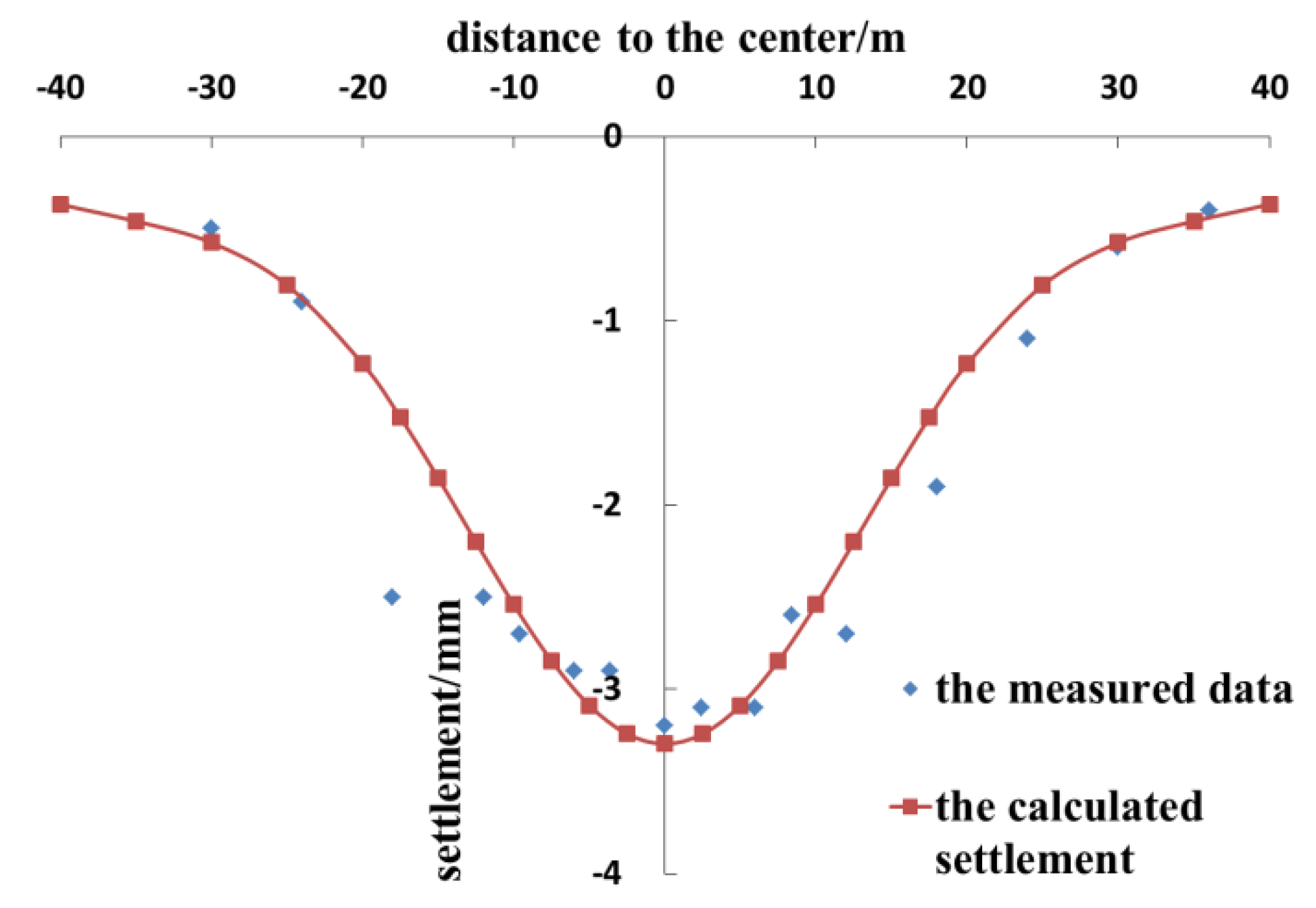
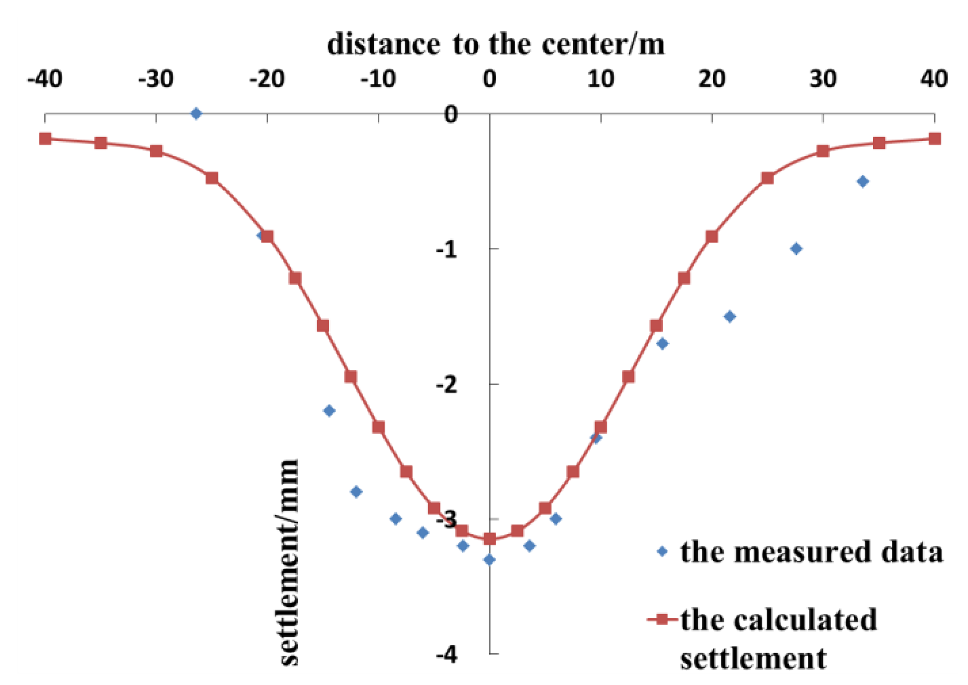
3.3. Reliability Verification

In the calculation process, the shield excavation surface is located at x0 = 40 m, and the volume expansion rate of the grouting ring is 1.58%. Figure 8 illustrates the comparison of the settlement distribution curves of the existing upline. According to the results, first, the settlement curve of the tunnel obtained from the proposed calculation method is roughly in the form of a normal distribution, and the measured settlement data also present a distribution of “large settlement values in the middle and small settlement values at both ends”. Thus, the overall distribution of the calculated settlement is similar to that of the measured settlement. Second, the measured and the calculated maximum tunnel settlement in the crossing center are 3.2 and 3.3 mm respectively, which denotes a difference of only 0.1 mm, thereby fulfilling the accuracy requirement. Third, the range of the settlement of the tunnel figured out by the proposed calculation method is relatively close to the measured range and is approximately symmetrically distributed about the crossing center.
Figure 9 depicts the comparison of the settlement distribution curves of the existing downline. It is obvious that, first, the measured data reveal that the settlement of the tunnel near the crossing center is relatively large, while the settlement on the two sides away from the crossing center is relatively small. The settlement distribution law is roughly consistent with the curve law obtained from the theoretical calculation method presented herein. Second, the measured value of the tunnel settlement near the center point is slightly greater than the theoretically calculated tunnel settlement. For example, the measured value of the central settlement is 3.3 mm, and the maximum settlement in the center figured out by the proposed method is 3.15 mm. The difference is only 0.15 mm, which satisfies the accuracy requirement.
In summary, the calculation results are in good agreement with the measured data, which proves the reliability of the proposed method. Also, the calculation method is able to figure out the settlement of the existing tunnel under the influence of the grouting ring of the new tunnel with an acceptable degree of accuracy. Therefore, it can be used to analyze the perturbation effect on the existing tunnels when the new tunnels are reinforced with grouting rings under the close tunnel crossing conditions, which has great significance in the actual engineering design.
The formation of the grouting ring is actually a compensation grouting technology. The compensation grouting of the lower tunnel will lift the upper tunnel, thereby reducing the settlement of the upper tunnel caused by shield excavation as well as ensuring the vertical deformation is in a safe range. If the effect of the grouting ring is too small, it will not have a good effect on suppressing the settlement of the tunnel; while if the effect of the grouting ring is too large, it may cause the existing tunnel to bulge. Therefore, it is essential to rationally design parameters such as the length of the grouting ring (L) and the volume expansion rate (Q). The theoretical calculation method provided in this paper can be used to calculate the vertical deformation of existing tunnels by substituting the design parameters of grouting rings, so as to verify the rationality of the design parameters of grouting rings.

4. Influence of a Single Factor on Existing Tunnels

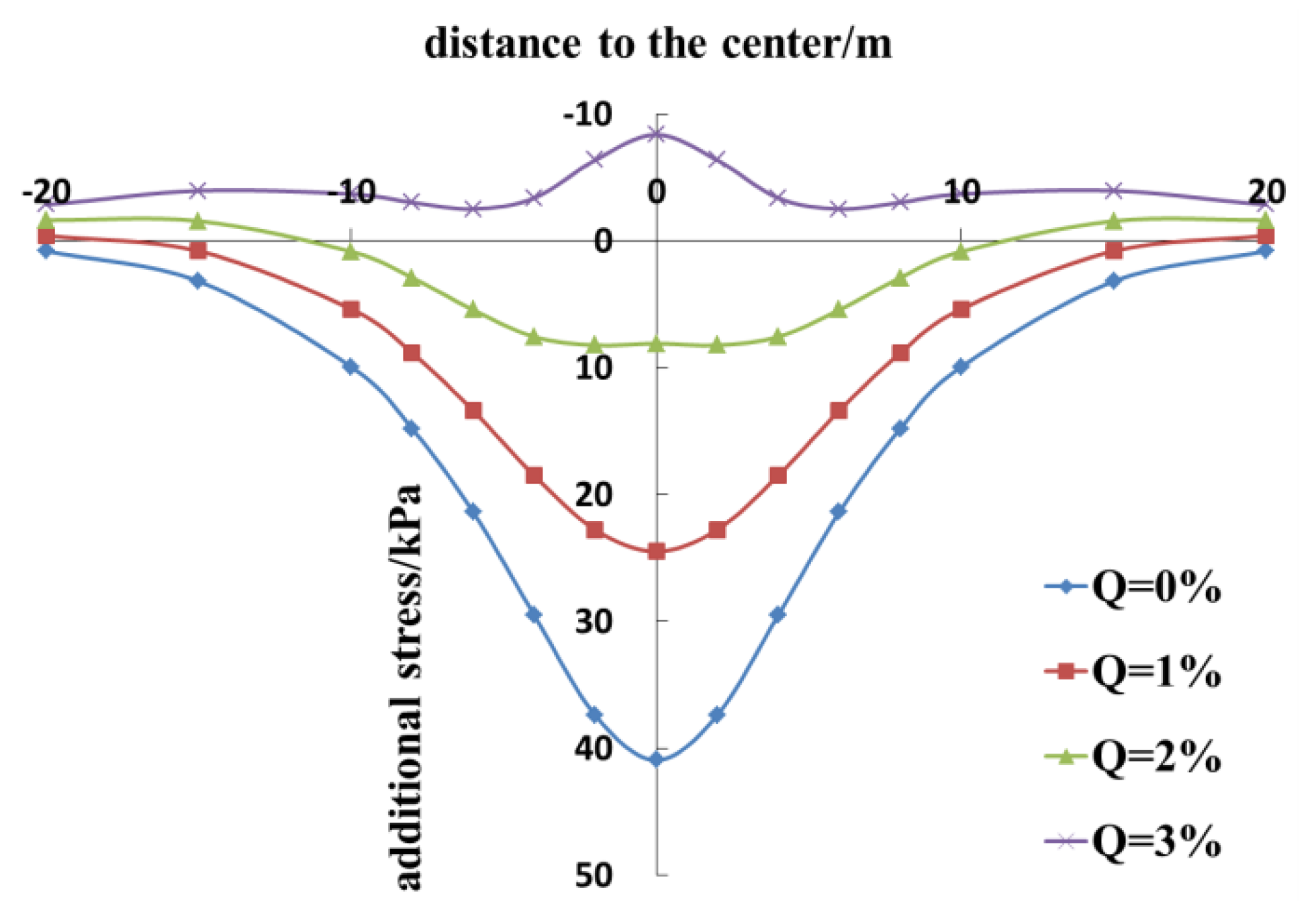
4.1. Volume Expansion Rate

The case of the above line tunnel is in standard working conditions. For the convenience of research, some parameters can be adjusted as follows: α = 90° and L1 = L2 = 15 m. The volume expansion rate is also set at 0, 1, 2, and 3%, and the other relevant parameters remain unchanged.
Figure 10 and Figure 11 show the comparison of the additional stress on and the vertical displacement of the existing tunnel at different volume expansion rates. These figures show that, first, when Q is 0%, the additional stress on the existing tunnel is normally distributed, and the maximum additional stress in the center is 40.92 kPa. Second, as Q increases, the force for lifting the existing tunnel, caused by the grouting ring, enlarges, and the total additional stress on the existing tunnel gradually decreases. When Q = 3%, the variation in the additional stress is transformed from a vertical downward trend to a vertical upward trend, indicating that the impact of the grouting ring is greater than that of the tunnel excavation. Third, the vertical displacement of the tunnel under the working conditions follows a normal distribution, and the maximum vertical displacement occurs in the crossing center. When Q is set at 0, 1, and 2%, the maximum settlement value is 9.12, 5.35, and 1.88 mm respectively. Fourth, the volume expansion of the grouting ring can effectively reduce the settlement deformation of the existing tunnel. With the continuous increase in Q, the settlement of the existing tunnel gradually declines. When Q = 3%, the deformation of the existing tunnel shifts from a settlement deformation to an upward bulge, and the maximum bulge in the center is 2.16 mm. Fifth, for this project, the optimal volume expansion rate (Q) should be controlled between 2–3% when the vertical deformation of the existing tunnel is the smallest at this time.

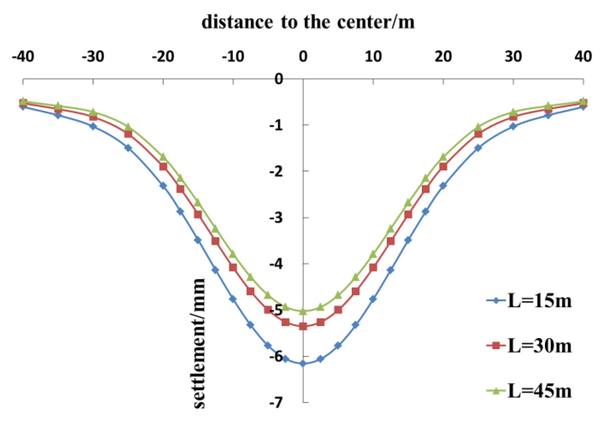
4.2. Length of Grouting Rings

α and Q are set at 90° and 1% respectively, while the length of the grouting ring is set at 15, 30, and 45 m as the research conditions; the other relevant parameters remain unchanged. When traversing a single-lane tunnel, the grouting ring is generally set symmetrically along the crossing center point, so L1 = L2 = 0.5 L.
Figure 12 and Figure 13 show the comparison of the additional stress on and the vertical displacement of the existing tunnels at different lengths of the grouting ring. It is clear that, first, at a grouting ring length of 15, 30, and 45 m, the additional stress on and the settlement of the existing tunnel gradually decrease. Moreover, at a grouting ring length of 15, 30, and 45 m, the maximum additional stress occurring in the crossing center is 26.77, 24.47, and 23.68 kPa respectively, and the maximum settlement of the existing tunnel reaches 6.15, 5.35, and 5.02 mm respectively. Second, an increase in the length of the grouting ring can reduce the settlement of the existing tunnel, but the effect gradually lessens.

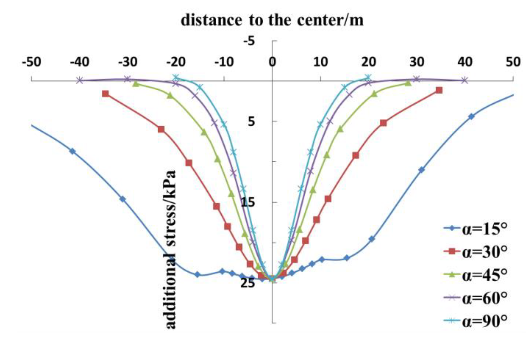
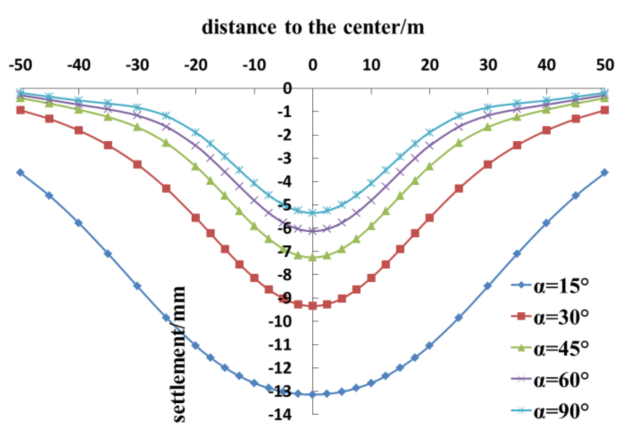
4.3. Tunnel Crossing Angle

L1 and L2 are set at 15 m, and Q is equal to 1%. The tunnel crossing angles are set at 15, 30, 45, 60, and 90°, and the other relevant parameters remain unchanged.
Figure 14 and Figure 15 delineate the comparison of the additional stress on and the vertical displacement of the existing tunnels at different tunnel crossing angles. According to these figures, first, as α decreases, the maximum value of the additional stress in the center of the existing tunnel remains almost unchanged at about 25 kPa, but the range of the additional stress on the existing tunnel increases. Second, when the tunnel crossing angle is greater than or equal to 30°, the additional stress follows a normal distribution. When α = 15°, due to the small crossing angle between the old and the new tunnels, the influence range of the excavation and the grouting ring on the existing tunnel increases. The additional stress curve near the crossing center becomes gentle due to the grouting ring. As the tunnel crossing angle continues to decline, the curve gradually bulges upward. Third, the additional stress curve is not symmetrically distributed along the traversing center. In fact, since the shield excavation surface is located at x0 = 40 m, the additional stress near the negative direction is slightly larger than that in the positive direction. Fourth, the settlement of the existing tunnel increases with the decrease in the tunnel crossing angle. Indeed, when α is set at 90, 60, 45, 30, and 15°, the maximum settlement of the existing tunnel across the center is 5.35, 6.13, 7.26, 9.34, and 13.14 mm respectively. Fifth, as α declines, the influence range of the settlement of the existing tunnels gradually extends.

5. Conclusions

From the findings of the current work, the following conclusions can be drawn:
  • The results of this theoretical calculation method are in good agreement with the measured data. The proposed method can be used to calculate the vertical displacement of the existing tunnel caused by a new tunnel crossing, under the influence of the grouting rings.
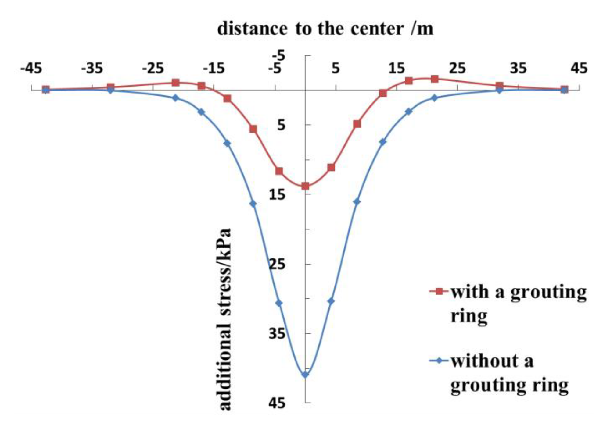
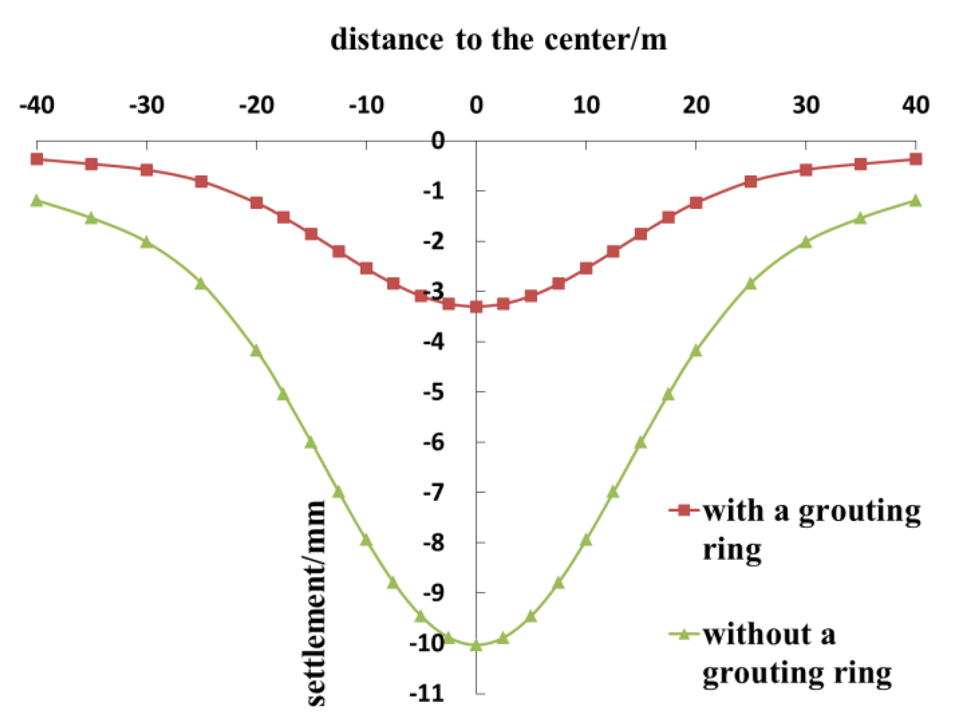
  • Installing grouting rings on new tunnels can effectively reduce the disturbance to existing tunnels caused by tunnel crossing and can significantly decrease the additional stress on and the settlement of the existing tunnels.
  • When the volume expansion of the grouted volume is within a certain range, increasing Q can effectively reduce the additional stress on and the settlement of the existing tunnel. When the volume expansion rate is too large, the impact of the grouting ring on the existing tunnel exceeds that of the tunnel excavation, and the variation in the additional stress on the existing tunnel shifts to a vertical upward trend; thus, the tunnel is bulged.
  • Properly increasing the length of the grouting ring can decrease the additional stress on and the settlement of the existing tunnel, but the effect gradually lessens. As the tunnel crossing angle decreases, the range of the settlement and the settlement value of the existing tunnel gradually rise.
In this work, the influence of the grouting ring is simplified as the volume expansion of the grouting area, without considering the changes in the mechanical properties of the surrounding soil that may be caused by the grouting. The volume expansion rate of the grouting ring is a significant parameter in the process of calculating the additional stress on and the displacement of the surrounding soil caused by the grouting ring. The steps to estimate the optimal volume expansion rate in the actual engineering are as follows. First, determine the relevant engineering parameters and establish a mechanical calculation model. Second, determine the initial volume expansion rate Q0 = 0 and substitute it into the calculation method in this paper. The vertical displacement value of the existing tunnel at the crossing center can be obtained as ω0 < 0 (a negative number indicates settlement). Third, take a new volume expansion rate Q1 = Q0 + △k (△k is the calculation accuracy, which can be determined artificially), and by substituting Q1 into the calculation method in this paper, the new vertical displacement value can be obtained as ω1. Fourth, if ω1 > 0, it means that the best volume expansion rate is between Q0 and Q1. If ω1 < 0, you need to take a new volume expansion rate Q2 = Q1 + △k, and by substituting Q2 into the calculation method in this paper, the new vertical displacement value can be obtained as ω2. Fifth, if ω2 > 0, it means that the best volume expansion rate is between Q1 and Q2. If ω2 < 0, you need to continue the above process, take Qi+1 = Qi + △k (i = 2,3,4,...,n). Substituting Qi+1 into the calculation method in this paper until ωi+1 > 0 is obtained, then the calculation can be stopped, and the optimal volume expansion rate of the grouting ring is between Qi and Qi+1.
For example, in Section 4.1 of this article, △k = 1%, when Q = 3%, the vertical displacement across the center ω > 0, which means that the optimal volume expansion rate of the grouting ring of this project is between 2–3%. If you want to determine a more accurate range, Δk needs to be smaller.

Author Contributions

Conceptualization, Y.Q.; Methodology, Y.Q.; Software, Y.Q.; Validation, Y.Q., G.W., and Y.X.; Data curation, Y.Q.; Writing—Original Draft Preparation, Y.Q.; Writing—Review and Editing, Y.Q., G.W., and Y.X. All authors have read and agreed to the published version of the manuscript.

Funding

This research was supported by National Natural Science Foundation of China (Grant No. 51778576).

Acknowledgments

We are grateful to other members of our research team (Zhang, X.H.; Yu, G.H.) for their technical support.

Conflicts of Interest

The authors declare no conflict of interest.

References

  1. Sun, L.; Liu, G.; Wang, Z.; Wu, S.; Hong, C. The shield tunnel obliquely crossing over an existing pipeline: A numerical analysis. Civ. Eng. Urban Plan. 2012, 748–754. Available online: https://ascelibrary.org/doi/abs/10.1061/9780784412435.136 (accessed on 10 September 2020).
  2. Yin, M.; Jiang, H.; Jiang, Y.; Sun, Z.; Wu, Q. Effect of the excavation clearance of an under-crossing shield tunnel on existing shield tunnels. Tunn. Undergr. Space Technol. 2018, 78, 245–258. [Google Scholar] [CrossRef]
  3. Sagaseta, C. Patterns of soil deformations around tunnels: Application to the extension of Madrid Metro. Comput. Geotech. 2001, 28, 445–468. [Google Scholar]
  4. Han, Y.; Ye, W.; Wei, Q. Research on the influence of new shield tunnel to adjacent existing tunnel. Appl. Mech. Mater. 2013, 295–298, 2985–2989. [Google Scholar] [CrossRef]
  5. Zhang, Z.; Huang, M. Geotechnical influence on existing subway tunnels induced by multiline tunneling in Shanghai soft soil. Comput. Geotech. 2014, 56, 121–132. [Google Scholar] [CrossRef]
  6. Li, X.G.; Yuan, D.J. Response of a double-decked metro tunnel to shield driving of twin closely under-crossing tunnels. Tunn. Undergr. Space Technol. 2012, 28, 18–30. [Google Scholar] [CrossRef]
  7. Zhang, Z.G.; Zhang, M.X.; Wu, H.M.; Xiao, X. 3D numerical simulation for mechanical influence of multi-line tunneling on existing tunnel in soft clay GB/T 7714. In Proceedings of the IET International Conference on Smart & Sustainable City, Shanghai, China, 6–8 July 2011. [Google Scholar]
  8. Jin, D.; Yuan, D.; Li, X.; Zheng, H. Analysis of the settlement of an existing tunnel induced by shield tunneling underneath. Tunn. Undergr. Space Technol. 2018, 81, 209–220. [Google Scholar] [CrossRef]
  9. Zhang, X.; Zhang, M.; Li, L. Research on construction disturbance caused by multi-line overlapped shield perpendicularly crossing. In Proceedings of the Tunneling & Underground Construction, Shanghai, China, 26–28 May 2014; ASCE: New York, NY, USA, 2014. [Google Scholar]
  10. Jin, D.; Yuan, D.; Li, X.; Zheng, H. An in-tunnel grouting protection method for excavating twin tunnels beneath an existing tunnel. Tunn. Undergr. Space Technol. 2018, 71, 27–35. [Google Scholar] [CrossRef]
  11. Peng, H.; Dong, Z.Y.; Liu, Y.L. Research on deformation influence of shield undercrossing the existing metro double shield tunnel. Adv. Mater. Res. 2015, 1065–1069, 378–382. [Google Scholar] [CrossRef]
  12. Au, S.K.A.; Soga, K.; Jafari, M.R.; Bolton, M.D.; Komiya, K. Factors affecting long-term efficiency of compensation grouting in clays. J. Geotech. Geoenviron. Eng. 2003, 129, 254–262. [Google Scholar] [CrossRef]
  13. Zhang, D.; Zou, W.; Yan, J. Effective control of large transverse deformation of shield tunnels using grouting in soft deposits. Chin. J. Geotech. Eng. 2014, 36, 2203–2212. [Google Scholar]
  14. Qi, J.; Xu, R.; Wei, G. Research on calculation method of soil 3D displacement due to shield tunnel construction. Rock Soil Mech. 2009, 30, 2442–2446. [Google Scholar]
  15. Wei, G.; Zhang, X. Calculation of rotation and shearing dislocation deformation of underlying shield tunnels due to foundation pit excavation. J. Cent. South Univ. (Sci. Technol.) 2019, 50, 2273–2284. [Google Scholar]
  16. Wei, G.; Yu, G.; Yang, B. Calculation of existing shield tunnel shearing dislocation platform deformation due to undercrossing new shield tunnel undercrossing. J. Hunan Univ. 2018, 45, 103–112. [Google Scholar]
  17. Mindlin, R.D. Force at a point in the interior of a semi-infinite soild. Physics 1936, 7, 195–202. [Google Scholar] [CrossRef]
  18. Wei, G. 3-D analytical solution of ground deformation induced by shield tunneling construction. In Proceedings of the Second National Conference on Engineering Security and Protection, Beijing, China; Chinese Society for Rock Mechanics & Engineering: Beijing, China, 2010; pp. 369–374. Available online: https://cpfd.cnki.com.cn/Article/CPFDTOTAL-ZGYJ201008003005.htm (accessed on 10 September 2020).
  19. Knothe, S. Observations of surface movements under influence of mining and their theoretical interpretation. In Proceedings of the European Congress on Ground Movement, Leeds, UK, 9–12 April 1957; University of Leeds: Leeds, UK, 1957; pp. 210–218. [Google Scholar]
  20. Zhou, S.; He, C.; Xiao, J. Energy method for calculation deformation of adjacent shield tunnels due to foundation pit excavation considering step between rings. China Railw. Sci. 2016, 37, 53–60. [Google Scholar]
  21. Wei, G.; Qi, Y.; Wu, H. Calculation of rotation and segment ring dislocation deformation caused by surcharge in shield tunnels. Tunn. Constr. 2019, 39, 1781–1789. [Google Scholar]
Figure 1. Diagram of the calculation model.
Symmetry 12 01623 g001
Figure 2. Schematic diagram of the action process of grouting rings.
Symmetry 12 01623 g002
Figure 3. Calculation model diagram of grouting rings.
Symmetry 12 01623 g003
Figure 4. The mechanical model of the volume expansion of the grouting rings.
Symmetry 12 01623 g004
Figure 5. Schematic diagram of the project.
Symmetry 12 01623 g005
Figure 6. Comparison curve of additional stress on the upline.
Symmetry 12 01623 g006
Figure 7. Comparison curve of settlement on the upline.
Symmetry 12 01623 g007
Figure 8. The comparison of the settlement distribution curves of the existing upline.
Symmetry 12 01623 g008
Figure 9. The comparison of the settlement distribution curves of the existing downline.
Symmetry 12 01623 g009
Figure 10. The comparison of the additional stress of the existing tunnel at different volume expansion rates.
Symmetry 12 01623 g010
Figure 11. The comparison of the vertical displacement of the existing tunnel at different volume expansion rates.
Symmetry 12 01623 g011
Figure 12. The comparison of the additional stress on the existing tunnel at different lengths of the grouting ring.
Symmetry 12 01623 g012
Figure 13. The comparison of the vertical displacement of the existing tunnel at different lengths of the grouting ring.
Symmetry 12 01623 g013
Figure 14. The comparison of the additional stress on the existing tunnel at different tunnel crossing angles.
Symmetry 12 01623 g014
Figure 15. The comparison of the vertical displacement of the existing tunnel at different tunnel crossing angles.
Symmetry 12 01623 g015
Table 1. Parameters of the project.
ParametersNew Tunnel
H17.6 m
R3.35 m
ηs2%
q45 kPa
f110 kPa
p120 kPa
d2.68 m
Es10.47 MPa
μ0.27
φ28°
ParametersExisting tunnels
UplineDownline
h11.0 m11.1 m
α62°61°
LL1 = 18.25 m
L2 = 31.25 m
L1 = 31.25 m
L2 = 18.25 m
Rs3.1 m
Dt1.5 m
EtIt (tunnel equivalent bending stiffness)1.1 × 10⁸ kN·m2
ks (shear stiffness between rings)7.45 × 10⁵ kN/m
kt (tensile stiffness between rings)1.94 × 10⁶ kN/m
J (coefficient of rotation effect of rigid body)0.3

