Abstract
The implementation of a decentralized blue–green infrastructure (BGI) is a key strategy in climate adaptation and stormwater management. However, the integration of urban trees into the multifunctional infrastructure remains insufficiently addressed, particularly regarding rooting space in dense urban environments. Addressing this gap, the BoRSiS project developed the soil-pipe system (SPS), which repurposes the existing underground pipe trenches and roadway space to provide trees with significantly larger root zones without competing for additional urban space. This enhances tree-related ecosystem services, such as cooling, air purification, and runoff reduction. The SPS serves as a stormwater retention system by capturing excess rainwater during heavy precipitation events of up to 180 min, reducing the pressure on drainage systems. System evaluations show that, on average, each SPS module (20 m trench length) can store 1028–1285 L of water, enabling a moisture supply to trees for 3.4 to 25.7 days depending on the species and site conditions. This capacity allows the system to buffer short-term drought periods, which, according to climate data, recur with frequencies of 9 (7-day) and 2 (14-day) events per year. Geotechnical and economic assessments confirm the system stability and cost-efficiency. These findings position the SPS as a scalable, multifunctional solution for urban climate adaptation, tree vitality, and a resilient infrastructure.
1. Introduction
The impact of climate change ranges from increased rainfall intensity to prolonged droughts that are profoundly affecting urban environments, many of which are ill-equipped to manage such extreme conditions [1,2]. Increasing rainfall variability leading to flooding or water scarcity, extreme temperatures exacerbating the effects of the urban heat island (UHI), and declining air quality are amongst the biggest challenges facing cities today and emphasize the need for innovative infrastructure solutions that integrate stormwater management and urban greening [1,3]. The traditional grey infrastructure, which prioritizes the rapid conveyance of stormwater through underground drainage systems, has proven insufficient in addressing these interconnected issues, as it disregards opportunities for local water retention, urban cooling, and ecosystem restoration [2,4]. In response, the blue–green infrastructure (BGI) has emerged as a multifunctional alternative, integrating hydrological and ecological processes within urban planning to enhance climate resilience, reduce flood risk, and support biodiversity [1,5,6,7]. BGI leverages nature-based solutions, such as wetlands, bioswales, rain gardens, and tree-based systems, to mitigate climate extremes while fostering sustainable urban development [8,9].
Among these solutions, urban trees play a pivotal role by significantly contributing to temperature regulation, air purification, carbon sequestration, and stormwater interception [10,11]. Large, mature trees are particularly valuable, as they provide exponentially greater shade, cooling, and stormwater retention capacities compared with younger trees [10,12]. The capacity of urban trees to provide optimal ecosystem services is contingent not only on maturity but also on adequate soil volume, root expansion potential, and hydrological stability. However, despite their well-documented benefits, urban trees often fail to reach maturity due to spatial constraints, inadequate rooting conditions, and conflicts with the underground infrastructure. Soil compaction, limited rooting space, and poor aeration constrain root growth, reducing trees’ access to nutrients and moisture, and reducing their structural stability [13,14,15,16]. Studies have demonstrated that root expansion is directly correlated with canopy development, meaning that trees with restricted root zones fail to establish expansive crowns, limiting their ability to regulate urban microclimates [17,18].
A primary limitation of urban tree survival is competition for space. The presence of subsurface utilities, including water pipes, sewer systems, and gas mains, directly impedes root expansion, causing mechanical conflicts that increase both maintenance costs and tree mortality rates [8,19]. Urban environments often feature compacted soils to support infrastructure loads, which severely restricts root growth and limits access to essential nutrients and water. This compaction not only stunts tree development but also forces roots to seek out less compacted areas, often leading to pavement heaving and damage. As a result, tree growth is frequently stunted, leading to reduced long-term viability and increased replanting requirements [4,20]. In many urban settings, trees are therefore confined within shallow, isolated planting pits, further restricting the access to essential soil volume [16]. Water availability presents another critical challenge. Hydrological instability, characterized by erratic soil moisture levels, exacerbates drought stress or waterlogging, both of which impair tree health and resilience [16,21]. Many urban soils are engineered for rapid water drainage rather than retention, leading to insufficient water availability for root uptake [22].
Egerer et al. [19] highlight the key challenges for urban street trees, including restricted soil volume, surface sealing, and construction-related root damage, which hinder their ecological benefits. The study calls for improved management strategies and increased community engagement to enhance urban tree resilience and functionality. Although the integration of urban trees into stormwater management systems holds significant potential, the implementation often remains fragmented and lacks a holistic approach. Many trees are planted in isolated locations without strategic alignment to urban hydrological networks, reducing their effectiveness as multifunctional climate adaptation tools [4,23]. Tree pits have been widely implemented as engineered planting environments designed to enhance soil conditions, increase water retention, and facilitate root expansion in urban areas, thereby contributing to urban cooling and flood mitigation [19,24]. As part of the BGI and therefore also of Sustainable Urban Drainage Systems (SUDSs) and Water-Sensitive Urban Design (WSUD) frameworks, tree pits have been integrated into city planning strategies, for example in Stockholm, New York, Melbourne, Montreal, Hamburg, and Beijing, where they serve as decentralized stormwater retention systems while simultaneously supporting tree growth [5,24,25,26,27,28,29,30]. One prominent example is Björn Embren’s large-scale tree pit installation in Stockholm [31], which is designed to provide ample rooting space and enhance stormwater management. These generously sized pits have demonstrated success in promoting tree vitality by reducing soil compaction and increasing water availability. Novak et al. [32] conducted a global sensitivity analysis on bioretention tree pit systems (BC-Ts), identifying the soil water-holding capacity, tree water uptake, and exfiltration as key factors influencing stormwater retention and runoff management. Richter et al. [3] conducted a global systematic review of tree-based BGIs, analyzing case studies that integrate stormwater management with urban forestry. Their findings confirmed that optimized tree pit designs enhance tree vitality, reduce urban flooding, regulate microclimates, and improve tree survival rates in dense urban environments. Bell et al. [33] examined how engineered tree pits optimize the root space beneath sidewalks, enhance structural support, and integrate stormwater management, enabling resilient designs that support tree growth while mitigating runoff and infrastructure conflicts.
While engineered tree pits have improved stormwater infiltration and root environments, they remain constrained by spatial and hydrological limitations [30,34,35,36]. Previous studies, such as Embren’s large-scale tree pits in Stockholm [25], have an enhanced and greater soil volume by utilizing coarse aggregate substrates, which enhance soil aeration, prevent compaction, and create favorable rooting conditions for urban trees. While widely adopted for urban forestry, their large spatial footprint limits implementation in dense cities, where high land-use competition restricts available space [37]. Similarly, BC-Ts have been designed to enhance stormwater infiltration and runoff management [32], but studies indicate that their effectiveness in sustaining tree moisture remains uncertain, as they primarily focus on infiltration rather than long-term water retention [38]. Additionally, other tree pit designs have exhibited waterlogging risks, where excessive water retention results in prolonged soil saturation, increasing the likelihood of root rot and overall tree mortality [30,34,39]. Furthermore, sidewalk-integrated tree pits, such as those analyzed by Bell et al. [33], attempt to mitigate conflicts with urban infrastructure but remain susceptible to the spatial constraints imposed by subsurface utility networks, which are predominantly located beneath sidewalks [40,41]. These persistent deficiencies highlight the need for an integrated approach that optimally balances rooting space, stormwater retention, and urban infrastructure compatibility.
This research addresses the limitations of conventional tree pits, emphasizing the need for a more integrated approach that effectively balances space constraints, water management, and urban infrastructure—ultimately to promote healthier urban trees. To this end, the study addresses the research question: How can multifunctional tree-based systems be designed and implemented to overcome spatial and hydrological limitations while remaining compatible with the existing urban infrastructure in order to enhance the BGI and improve site conditions for urban trees? To answer this question, various analyses were conducted, including the assessment of drought periods because of their impact on tree vitality, the evaluation of precipitation patterns prior to these periods, and investigations into both infiltration and water-retention capabilities to sustain trees during dry spells. In addition, consideration was given to how these elements could be harmonized with existing road infrastructure, while ensuring sufficient rooting space and proper water distribution to support the long-term health of urban trees. The outcome of this comprehensive evaluation is the soil-pipe system (SPS), a novel, multifunctional solution that unites hydrological and ecological functions while remaining adaptable to urban contexts. The SPS was developed as part of the joint research project BoRSiS (Boden-Rohr-System als innovatives Element der klimaangepassten Stadtentwässerung—Soil-Pipe System as an Innovative Element of Climate-Adapted Urban Drainage). It represents a paradigm shift in the tree pit design by utilizing underground pipe trenches as extended root zones, significantly increasing the available soil volume while simultaneously functioning as a water-retention system. Unlike traditional tree pits, the SPS integrates directly into existing underground utility corridors, repurposing them as functional root zones rather than requiring additional excavation. This maximizes the rooting space while avoiding conflicts with infrastructure—a major limitation of previous designs. Additionally, the SPS introduces a water retention and slow-release mechanism, strategically storing stormwater within the pipe trench rather than directly at the tree planting site. By utilizing the expanded root zone for retention and a delayed release, the system prevents excessive water accumulation at the tree base, thereby mitigating waterlogging risks while ensuring sustained moisture availability. This approach directly addresses the persistent weaknesses of different designed tree pits, which often suffer from waterlogging or rapid drainage loss. Through this multifunctional approach, the SPS enhances tree survival rates while reducing urban stormwater burdens. This design not only mitigates the competition between trees and underground utilities but also addresses one of the causes of urban tree mortality: insufficient rooting space [14,30,34,42,43]. By leveraging the pre-existing subterranean infrastructure, the SPS facilitates deep and lateral root expansion, overcoming the compaction and mechanical barriers that hinder conventional tree pits. Moreover, its industrial collaboration framework ensures the integration of durable, sustainable materials, such as ductile cast-iron pipes and stone wool, which support the circular economy principles. The high absorption capacity of stone wool provides immediate stormwater retention, alleviating pressure on drainage networks, while ductile cast-iron pipes, known for their root resistance and adaptability, enable long-term structural resilience in urban environments. This innovative integration of subterranean infrastructure and tree-supporting elements maximizes the available urban space [44].
To validate the effectiveness of the SPS, this study employs a multi-method approach. The interdisciplinary consortium of the BoRSiS project includes urban water management specialists, water hydraulics experts (with a test facility), geotechnical engineers, economists, a botanist, and industry partners from the cast iron and stone wool industry, as well as a representative from a municipality to support project implementation. The general structure of the system is shown in Figure 1. Both the structure and, in particular, the arboricultural considerations are discussed in Section 2. The properties of the industrial partners’ products—cast-iron pipes and stone wool—which played a crucial role in the implementation, are presented in Section 2.1. In this context, the load-bearing capacity of the road according to German regulations is briefly addressed in Section 2.1, demonstrating how the stone wool elements meet this. To demonstrate the necessity and general performance of the system, climate data on rainfall, air temperature, and drying times were analyzed exemplarily based on the pilot regions, and a sizing guideline was developed (Section 2.2, Section 3.1 and Section 4). Hydraulic investigations on the filling process of the SPS, its storage capacity, and the delayed release of rainwater to the roots were carried out using a laboratory test setup (Section 2.3, Section 3.2 and Section 4). Additionally, the institutional framework conditions for the implementation of the SPS were investigated, and a cost–benefit analysis (CBA) was caried out (Section 2.4, Section 3.3 and Section 4). Finally, Section 3.4 presents the successful planning of the SPS through selected pilot projects. The interconnection of the individual research components leading to a holistically functioning SPS is illustrated in Figure 2.
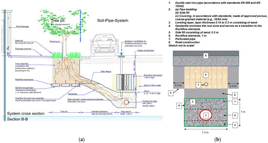
Figure 1.
System cross-section: (a) System cross-section as result of the studies at the tree pit; (b) More detailed cross-section through the pipe trench/soil-pipe system.
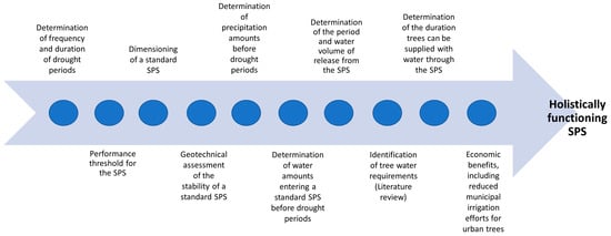
Figure 2.
Association chain of the BoRSiS research project to create a holistically functioning SPS.
2. Materials and Methods
The functionality of the SPS can best be explained using a cross-sectional view of the linear system (Figure 1a,b).
The cross-sectional view of the system illustrates the distinction between the conventional tree pit and the SPS. It is important to note that almost every tree pit, newly built or even with older and already established trees, can be connected to the SPS. The roots of the thriving tree will grow into the trench between the tree location and the SPS, following the infiltrating water, as illustrated by the blue wavy arrows in Figure 1a. The trench is composed of coarse material, which creates a large pore volume, enabling aeration and ventilation to ensure essential gas exchange within the trench. This feature is particularly critical for tree roots, which have a high oxygen demand and release carbon dioxide during growth [45]. Furthermore, nutrient-enriched soil amendments, such as biochar, are incorporated into the trench substrate, to further enhance the growing environment and to support the overall effectiveness of the SPS. The system includes several outlets to facilitate effective ventilation and maintain optimal conditions. The long-term water supply in the pipe trench is achieved through a layered construction of stone wool elements and sand.
The stone wool functions as a soakaway element for stormwater, helping to relieve the pressure on the sewer system [46]. The water primarily remains in a sand layer situated beneath the stone wool above the pipe trench, providing water and moisture to the surrounding soil. This results in an enhanced water supply for the tree for up to two weeks (Section 4). As illustrated in Figure 1b, it is important to ensure that the cast-iron pipe (1) (wastewater pipe) is correctly embedded in the coarse material (2) during installation. Firstly, a bedding layer (2a) must be created beneath the pipe, followed by the side fill (2b) to stabilize the pipe’s position. Finally, the pipe is fully encased by the coarse material with a top covering (2c). A sand layer (3), varying between 15 and 30 cm in thickness, is applied on top. The sand layer acts as a water reservoir and ensures a levelled foundation for the stone wool elements (6). To prevent the sand, the soil, and the coarse material from mixing, the coarse material is wrapped in a geotextile (4). The stone wool elements (6) must be installed with 30 cm of working space on both sides, which is subsequently backfilled with sand (5). The sand and various layers are compacted after the installation. The stone wool elements have a preformed cavity for water transport. To ensure uniform water distribution within the stone wool, an additional perforated pipe (7) should be installed. A smaller cavity is designed for the ventilation of the stone wool. Finally, the road construction (8) can be built above the installed elements.
For a holistic assessment of the system, not only is its described functionality crucial, but also the determination of the water demand (drought periods and the resulting need for tree irrigation) and water availability (water volume within the system and its gradual release). Additionally, geotechnical investigations should assess the system’s stability, and an (economic) evaluation should be conducted to determine the potential benefits of the system. These aspects can be derived from an association chain (Figure 2).
2.1. Industry Product Description
As part of the research project, the funding agency (BMBF) required a practical application component involving industry partners. The following section describes the essential products for this project—stone wool and ductile cast-iron pipes—along with their respective properties.
2.1.1. Stone Wool
The SPS concept uses stone wool as a medium to attenuate runoff peaks and to gradually infiltrate rainwater runoff. The runoff is conveyed via gullies and pipes to the subterranean stone wool soakaway located at the top half of the SPS. The solution presented in this paper consists of stone wool elements with a nominal size of 1.2 m × 1.0 m × 0.15 m. These differ from stone wool insulation products in that they are rigid, load-bearing, and hydrophilic. Subsequently, the water will slowly percolate into the sand layer and the extended root zone situated beneath it. Stone wool has been used as a soakaway system in a number of BGI projects in Europe. In this section, we will discuss its suitability for the SPS. The following selection criteria were applied in the search for an attenuation medium for the release of runoff water into the SPS, most of which are presented in Table 1:

Table 1.
Criteria for the selection of the soakaway/attenuation medium.
The product Rockflow®, manufactured by ROCKWOOL Rain Water Systems (ROCKWOOL B.V., Delfstoffenweg 2, 6045 JH Roermond, The Netherlands) from fully circular stone wool, was found to meet the above criteria. In comparison with gravel or coarse material with a void ratio of 30–40%, stone wool displays a significant higher void ratio of up to 95%. The product is currently employed in over 350 climate adaptation projects, predominantly in the Netherlands and Denmark, to facilitate the localized drainage of runoff and the prevention of pluvial flooding and sewer spills.
The expected place where the SPS will be used is under trafficked areas, e.g., roads, squares, parking, and pedestrian areas (loading class 3.2). It was, therefore, required in this project that the system met the German stiffness and deformation requirements for road foundations. These findings may also support the potential application of SPS under the trafficking areas in other countries. According to German regulations, a deformation modulus of Ev2 ≥ 45 MN/m2 or 45 MPa is required for the substructure (planum) of the road [47]. In order to achieve this value, a layer of compacted aggregate was placed on top of the stone wool as a sub-base for the road construction. The recommended aggregate is a mixture of larger, sometimes crushed stones with smaller stones or particles.
Field tests were carried out to investigate the required thickness of compacted sub-base gravel to achieve the Ev2 ≥ 45 MN/m2 deformation modulus value. To this end, a full-scale linear system of stone wool with various thicknesses of compacted sub-base aggregate on top was constructed. The test comprised ten sections on which twenty plate load tests according to DIN 18134 and sixty dynamic tests were carried out [48]. The literature describes the correlation between the modulus of the subgrade deformation and the thickness of the aggregate required to increase the modulus of subgrade deformation [49]. For example, a subsoil of 10 MN/m2 would require 0.45 m of aggregate to achieve the 45 MN/m2 required for the substructure (Figure 3).
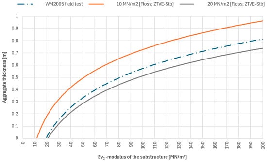
Figure 3.
Diagram to determine the modulus of deformation Ev2 for different aggregate layer thicknesses. The orange and grey lines represent a sub-base with a deformation modulus of 10 MN/m2 and 20 MN/m2, respectively, and the correlation with the compacted aggregate layer required to meet the requirement of Ev2 = 45 MN/m2 for the sub-base (planum) [49]. The blue dashed line represents the measured correlation between the modulus of deformation and the thickness of the compacted aggregate on the stone wool (WM2005).
2.1.2. Ductile Cast-Iron Pipes
About 150 years ago, the municipal infrastructure supplying drinking water to the population was built almost exclusively with cast-iron pipes. A significant proportion of the networks in operation today still date from this period. Since then, the cast-iron pipe system has undergone a significant development: ductile cast iron has made it possible to withstand higher mechanical loads while reducing the weight. Protection against internal and external chemical attack has been perfected, and pipes, fittings, valves, and accessories have provided a complete system for all the applications. Today, the system of ductile cast-iron pipes, fittings, valves, and accessories ensures the trouble-free and economical transport of mainly liquid media (water and waste water) [50].
In line with the circular economy, the components are largely made from scrap—up to 95%. Special features are the high contact pressures of the socket joints, which make the pipe system resistant to root growth, and the cement mortar coatings, which make it possible to create root zones with coarse gravel.
This and root-resistant pipes are the prerequisite for the paradigm shift proposed in this paper, as currently, pipe trenches are highly compressed to both ensure secure bedding for the pipes and to keep the roots from entering the pipe trench. By deviating from this practice, the pipe trench can be utilized with the benefits illustrated above.
Ductile cast-iron pipe systems are standardized by the European Committee for Standardization CEN/TC 203 cast-iron pipes, fittings, and their joints. The members of the committee started early to develop the rules for Sponge City applications. This was also performed with a view to the Europe-wide implementation of the construction methods developed in the BoRSiS project using ductile cast-iron pipes. These include:
- EN 598: Ductile iron pipes and associated components for sewerage applications—Requirements and test methods, 2009-10 [51];
- EN 15542: Ductile iron pipes, fittings, and accessories—External cement mortar coating for pipes—Requirements and test methods; German and English version prEN 15542:2021 [52];
- EN 17970: Ductile iron pipes—Push-in joints for ductile iron pipe systems—Resistance against root penetration—Requirements and test methods; German version EN 17970, design as a linear element 2024-08 [53].
The development of a technical code for Sponge City applications has been included in the work program of TC 203. Here, too, the results of the BoRSiS project are being incorporated directly into the work on the technical standards.
2.2. Climate Data Analyses and Dimensioning of the SPS
Climate change signals from various pilot municipalities were examined. For this purpose, the hydrometeorological grid dataset (HYRAS v5.0) for Germany, provided by the German Weather Service (DWD) as an open-source resource [54], was analyzed using the R programming language. The precipitation data cover a 92-year period from 1931 to 2022, while the temperature data (daily minimum, average, and maximum) are available for 70 years from 1951 to 2020. For consistency cross analyses, 3 × 3 grid cells (9 km2) were selected in each of the evaluated pilot municipalities. Dry days were defined as those with daily precipitation totals of ≤1 mm. This analysis enabled the evaluation of drought periods of varying lengths and their distribution over the year, offering insights into the potential frequency of drought stress for urban trees. By breaking down the data by month and incorporating knowledge of the trees’ water requirements throughout the year, the months in which the system is likely to be most frequently utilized were identified. Additionally, precipitation events prior to these drought periods were considered. These two factors provided key insights into how frequently the SPS might be relevant for water storage annually (during drought periods) and how much water would be available in the system during those times (precipitation before drought periods). Besides drought periods, heat stress is another significant factor affecting urban trees and contributing to the intensity of drought periods [55,56]. Therefore, summer days (≥25 °C) and hot days (≥30 °C) were also incorporated into the analysis. This enabled the identification of dry and warm periods, along with their frequencies. These insights were valuable in helping to dimension the system appropriately.
For the dimensioning process, the water requirements of the trees are crucial. A literature review revealed that this aspect is particularly challenging to calculate. Factors influencing the water demand include the age of the tree, its location, and the prevailing climate, among others. On average, a tree with roots reaching the pipe trench requires approximately 50 to 300 L of water per day [57,58,59,60,61].
The system’s dimensioning itself was based on current German regulatory frameworks [42,62]. The available retention volume was determined ensuring a conservative approach. The tree pit, the interface between the tree pit and the pipe trench, and the volume in the pipe trench that is connected to the interface were excluded from this calculation, because it was assumed that the tree’s roots will spread into the trench, occupying some of the pores. By excluding these parts of the system, the pore volume occupied by roots could be calculated for the entire trench. Also, the leveling layer (sand) was not included in this calculation, as it was regarded as part of the system’s permanent water storage, in contrast to the retention volume available for rainfall events. The formula used for this calculation is as follows:
Here, represents the total volume, which is composed of the volume of the stone wool and the volume of the pipe trench . These volumes are each calculated based on the porosity (), width (), height (), and length (L). For the volume of the pipe trench, the sewer pipe volume is subtracted from the total calculation.
Moreover, the potential surface area that can be connected to the system was determined. The calculation assumed the cross-section of a traffic-calmed street, including the sidewalks and adjacent buildings. Finally, local precipitation data (KOSTRA DWD) [63] were used to determine the annual return periods and duration levels for the dimensioning of the system. The permissible precipitation amount that the system can accommodate was determined by calculating the retention volume per meter of pipe trench, adjusted by subtracting the portion of the trench volume connected to the interface, assuming that trees are planted every 20 m and that the interface covers a length of 1.5 m. This value was then divided by the cross-sectional area of the road surface. Based on the available volume within the trench, the system has a sufficient capacity to retain the water volume required for the 20-year flood event standard [62] up to this point, even without infiltration. The formula used for this calculation is as follows:
Here, represents the permissible rainfall that can be absorbed by the SPS. This amount is derived from the volume of a section which in turn is calculated using the total volume determined in Equation (1), multiplied by the system length minus the tree locations (This value is then divided by the area to be connected ( and scaled to the total system length (). Therefore, infiltration was considered only after a duration of 360 min. The infiltration rate of the system was subsequently calculated according to the standard formula provided by the German regulator DWA [64].
In all the pilot municipalities, it should be proven that flooding can be prevented in a 20-year event, so that the system is approved for the German market according to the enforced regulations [62]. All the ideas and partial results were transferred from theory to practice through pilot projects. Collaboration with practice partners was a key element in the successful implementation of the theoretical system. Based on the feedback from these partners, many valuable insights were incorporated into the methodology.
2.3. Hydraulic Analyses
As part of the project, hydraulic analyses focusing on the filling and emptying processes of the SPS were carried out. The practical implementation of the system was investigated using a laboratory test facility. The system must be able to fill quickly during a rainfall event, but the emptying must be delayed in order to maximize the retention effect. A key objective of the system is to store a high proportion of the rainfall to make it available to plants and trees. From the abovementioned requirements, questions could be derived regarding the flow processes, which are of crucial importance for the filling and emptying processes.
A 1:1 scale test was set up in the Hydraulic Engineering Laboratory at the Bochum University of Applied Sciences, in which different materials, layer structures, and heights were tested (Figure 4a,b). In coordination with the project consortium, potentially suitable materials were identified and analyzed in the test setup (sand, geotextile, gravel). The test facility was equipped with a variety of measuring instruments that allow for the detailed analysis of the tests. The instrumentation included a magnetic inductive flow meter to measure the inflow volume and several water level sensors to measure the fill level. The test setup was designed as a steel tank with a width of 1.25 m, a length of 10.0 m, and a height of 2.50 m. Figure 4 shows the test tank and an example of an experimental setup of the pipe system.
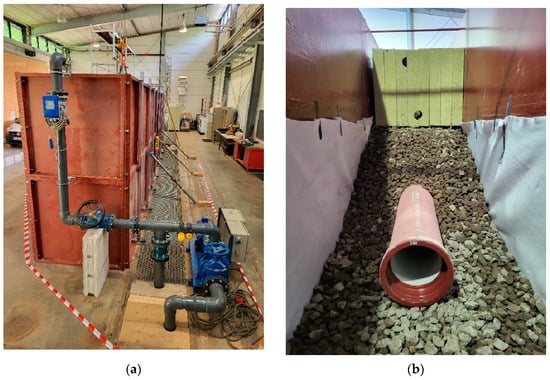
Figure 4.
(a) Side view of the tank with the feed pump and return channel and (b) exemplary illustration of the experimental setup in the 1:1 large-scale experiment.
Additional small containers measuring 0.90 m × 1.20 m × 1.20 m were also used for the preliminary tests. In these, different materials and layer structures could be experimentally evaluated without much effort.
The experiments were carried out with different quantities of water. The reactions in the system were analyzed on the basis of the data recorded. In particular, the tests were designed to answer the following questions:
- How long do the filling and emptying processes take?
- How much water can be stored in which layers?
- How long can this water be stored or made available to the tree?
2.4. Institutional Framework and Cost–Benefit Analyses
The economic evaluation encompasses two key areas of analysis. First, the institutional framework conditions necessary for the implementation of the SPS were examined. Second, a cost–benefit analysis (CBA) was conducted to evaluate the economic viability of the system.
These two subtopics are interrelated. Assuming that the benefits of the SPS outweigh its costs, the CBA serves as a critical tool to provide stakeholders with the economic justification required to support its implementation. The analysis is grounded in the principles of New Institutional Economics, particularly emphasizing the distinction between formal and informal institutions and the application of principal-agent theory. This framework facilitates a deeper understanding of the institutional and economic dynamics underpinning the feasibility and adoption of the SPS.
2.4.1. Institutions and Actor Analysis
Institutions represent the social rules and enforcement mechanisms under which action is taken [65]. Institutions can be divided into formal (laws and regulations) and informal institutions (morals, values, attitudes, tradition). They limit the actors’ room for maneuver, reduce uncertainties, and lower transaction costs for obtaining information [66]. Even if formal institutions have an important function, informal institutions are at least as important.
According to the rational choice approach, posts within an organization like a municipality have to be regarded as shells for the individual interests of the people working in these organizations [66]. This makes the analysis of what shapes their decision-making behavior relevant [67].
The asymmetrical distribution of information is an additional complicating factor here. According to the principal-agent theory, one of the negotiating partners has less information (principal; here, for example, the department responsible for water in a municipality) than the other negotiating partner (agent; here, for example, the person responsible in the road construction department). The aim of the study was to identify the conditions and best practices that prevent or at least minimize the agent from taking advantage vis-à-vis the principal [68].
To this end, an analysis of the organizations or players involved was carried out first. Such a, so-called, stakeholder analysis is used by politicians and organizations to improve the planning and implementation of projects [69,70,71]. It helps to better understand the problems affecting the project, to better coordinate interactions between the groups involved [69], and to minimize any advantage that the agent may have over the principal. Stakeholder or actor analysis is one of the most frequently used methods for identifying the parties involved and their interests [72].
The planning and implementation of the BGI involves a large number of different stakeholders with different participation rights and interests [69]. An actor analysis is particularly useful here due to the prevailing overlapping systems and stakeholder interests, the special market conditions under which wastewater is disposed of [69], and the fact that only a few political and economic actors are responsible for the management of stormwater. The interests and institutional perspectives [73] identified with the circle of stakeholders outlined in this way help to identify and eliminate conflicts of interest and uncertainties in the planning process at an early stage.
2.4.2. Cost–Benefit Analysis
The economic viability of an option considered is a key selection criterion for the stakeholders involved and authorized to make decisions [74]. Cost–benefit analyses (CBAs) are often used to assess the economic aspects in order to provide a further basis for the decision in favor of a planned system [75,76,77].
A CBA essentially comprises the following four steps [78,79]:
- Identification of all the welfare-relevant effects of the measure;
- Monetization of the relevant benefit and cost variables;
- Discounting of the future benefits and costs;
- Determination of the net values/overall assessment.
The classical CBA assumed so far claims to translate all the consequences of a measure into monetary units. In contrast, the non-monetary CBA only assigns monetary units to those benefit (and cost) categories for which these data can be determined with relatively little effort. All other benefit (and cost) categories are determined mainly qualitatively. A qualitative expert assessment is therefore required for the overall evaluation [77].
As part of this project, the costs were presented in comparison with conventional systems. The same applied for SPS regarding avoided costs, which were estimated together with the pilot municipalities. Benefits with negligible private, but great social, benefits were not calculated in our own primary evaluation. Instead, the benefit transfer methodology was used [80].
3. Results
3.1. Climate Data Analyses and Dimensioning of the SPS
As an example, the pilot municipality of Leichlingen (Rhineland, Germany) was analyzed to examine the distribution and frequency of drought periods from 1931 to 2022. Leichlingen is characterized by a temperate oceanic climate (Köppen–Geiger classification: Cfb) [81]. Leichlingen was selected because it represents the most advanced stage of project implementation. This analysis aimed to determine how often trees are exposed to drought stress conditions and assess how the SPS could help to mitigate these effects.
Drought periods were defined as sequences of at least 7, 14, 21, or 28 consecutive days with daily precipitation totals of ≤1 mm. The depiction of drought periods using the example of Leichlingen is illustrated in Figure 5.
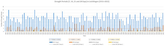
Figure 5.
Depiction of drought periods in the pilot city of Leichlingen from 1931–2022.
There was an inverse relationship between the duration of the drought periods and their frequency of occurrence. Between 1931 and 2022, a 7-day drought period occurred on average 9 times per year (range: 5–14 times), while a 14-day drought period occurred on average 2 times per year (range: 0–7 times). For these drought periods, assuming that sufficient rainfall precedes the drought, the SPS can ideally provide stored rainwater to the roots (Section 4). The longer drought periods depicted occur less than once per year. In such cases, the SPS can significantly reduce either the duration of drought stress or, alternatively, the duration of irrigation required. All the analyzed drought periods exhibit negligible trends of increased frequency over time.
The distribution of the drought periods throughout the year is essential for understanding when the system is most frequently needed to mitigate drought stress for the trees. An analysis of the distribution of the drought periods by month for the city of Leichlingen is presented in Figure 6.
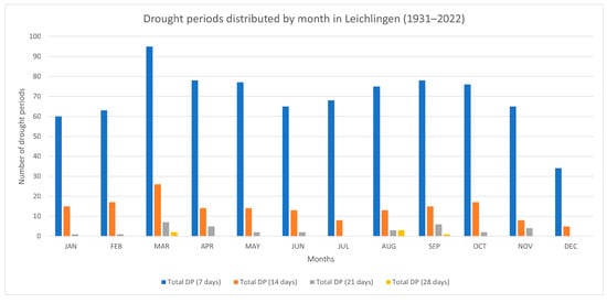
Figure 6.
Depiction of the monthly distribution of drought periods in the pilot city of Leichlingen from 1931–2022.
The drought periods showed variability throughout the year, with a notable increase in spring, particularly in March. Comparing the drought period distribution with the tree water demand highlights that the peak water needs occur in spring, particularly in March [56,61,82]. This emphasizes the critical need for water availability during this period to meet the heightened demand of the trees.
Additionally, precipitation events occurring prior to the drought periods were analyzed to assess the water availability in the system during these phases. The results of this analysis, exemplified by the city of Leichlingen, are presented in Table 2.
Table 2.
Precipitation before drought periods in Leichlingen (1931–2022).
As shown in Table 2, in 75% of cases (Table 2, 25th percentile), 4.7 mm of precipitation would have been available to be directed into the SPS. In 50% of cases (Table 2, median), this amount reached 9.7 mm. These values were calculated based on the average number of days with precipitation prior to a drought period (three days) and the cumulative precipitation sum over those days. These results were further utilized to determine the amount of water available to the trees over a period of approximately 14 days after the rain event (see Section 4).
Theoretically, based on the daily water consumption of 50–300 L mentioned in Section 2.2 and the values of 1028–1285 L discussed in Section 4, which are released gradually over time, the trees could be irrigated for approximately 3.4 days (1028/300—at maximum consumption) to 25.7 days (1285/50—at minimum consumption).
Building on Martonne’s insights [55], it is evident that the drought conditions are influenced not only by precipitation levels but also by temperature. Consequently, additional analyses were undertaken to assess the occurrence of summer days (Tmax ≥ 25 °C) and hot days (Tmax ≥ 30 °C), providing a more comprehensive understanding of drought dynamics. Both parameters followed the global trend and have approximately doubled over the past 70 years. As a result, increasing transpiration and a corresponding rise in the water demand of trees are to be expected in the future.
For the dimensioning process, the calculations followed the methodology outlined in the Materials and Methods section, based on the construction details illustrated in Figure 1. The key results are presented in Table 3.
Table 3.
Evaluations of the dimensioning for a standard soil-pipe system (SPS).
Based on Table 3, it is evident that a standard element of 20 m length, connected to a surface area of 26.5 m2/m, can accommodate precipitation volumes of 55.3 mm. With increasing hydraulic conductivity (kf-values), and with longer rainfall duration periods, the additional capacity due to infiltration increases absolutely and as a percentage of the total absorption capacity. In suitably permeable soils (kf-values), this ensures that even for long-duration rainfall events, the failure frequency can be kept to less than once in 20 years. To illustrate the system’s performance, local precipitation data (KOSTRA DWD) for the city of Leichlingen were used.
Figure 7 illustrates that for the city of Leichlingen, the SPS can manage flood control (T = 20 years) for durations up to D = 540 min. The system is capable of retaining events with a return period of T = 100 years for a duration of D = 180 min. As previously mentioned, the performance of SPS during longer-duration rainfall events is expected to be influenced by infiltration, which is in turn determined by the kf-values, duration steps, and return periods.
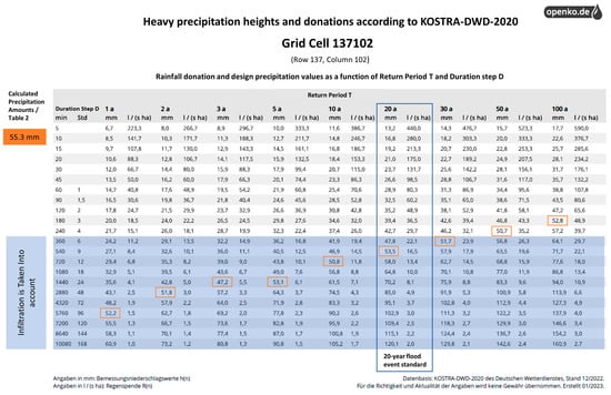
Figure 7.
Representation of precipitation in Leichlingen based on KOSTRA data from German Weather Service (DWD) provided via openko.de [63]. The values highlighted in orange refer to the permissible precipitation amount that the SPS can accommodate without infiltration, considering a single tree pit in this specific example. They illustrate the system’s retention capacity. The area highlighted in light blue indicates from which duration steps (D) onward site-specific infiltration can additionally be taken into account.
3.2. Hydraulic Analyses
On the basis of the tests carried out, the previously posed questions could be answered. The experiments started by analyzing the effect of the stone wool elements. The investigations also showed that the storage effect of the system does not depend on the stone wool elements, but rather on the sand layer underneath them. As demonstrated in Figure 8, two identical tests were conducted, with 54 L of water introduced into the system within a 15-min timeframe. The distinguishing factor between these experiments was the method of water introduction: in the first experiment (a), the water was introduced into the stone wool elements, while in the second experiment (b), these elements were removed and the water was directed directly onto the sand layer. A comprehensive analysis of the water discharges reveals only negligible differences between the two experiments. Specifically, in experiment (a), a water volume of 40 L was attained after 1.5 days, while in experiment (b), the same outcome was observed after 2.5 days. Subsequent to a 7-day period, the water output in both trials converged at a comparable value of approximately 45 L. Nevertheless, the stone wool elements are an essential component of the SPS as they ensure rapid water absorption.
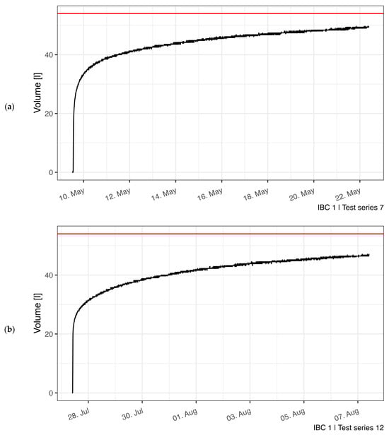
Figure 8.
Comparison of the water output (a) with Rockflow and (b) without Rockflow. The remaining parameters of the test setup were identical for both tests.
Different sand layer thicknesses and different infill materials for the leveling layer were also analyzed. No significant differences were found in the results; therefore, the system cross-section (Figure 1a) shows a range in the layer thickness of 0.15–0.3 m of sand. The large-scale test also showed that the distribution of water injected through the integrated pipe of the Rockflow® elements was not as expected. An analysis of the water level sensors revealed that the release occurred within the initial one or two Rockflow® elements and not over the entire length. In some instances, a reverse flow was observed. Consequently, a drainage pipe was installed within the integrated pipeline, which markedly enhanced the inflow into the stone wool elements. Furthermore, it was established that the release of water to the root area occurs within a period of 30 min to 2 hours following a precipitation event. Over a period of 6–12 twelve hours, approximately 60–70% of the water was released to this area, and after a maximum of 24 h, 75–80%. The results of a test are shown as an example in Figure 9. The red line represents the amount of water discharged and the black line the amount of water released from the sand layer, showing that most of the injected water has seeped through the sand layer into the lower part of the system after just one day. Even after 14 days, not all of the water had been released from the sand layer (Figure 9). Additionally, the maximum quantity of water that the distinct layers can accommodate was ascertained. It should be noted that all the values are associated with the 1:1 test setup and its dimensions. By the time the initial water level was detected in the lower area, a volume of approximately 0.86 m3 of water could be introduced into the system. Therefore, this quantity could be retained by the sand and the Rockflow® elements. Until the root area was completely filled with water, a total of 11 m3 was introduced. Subtracting the 0.86 m3 from this value results in a volume for the root zone of 10.14 m3 with a pipe zone length of 10 m.
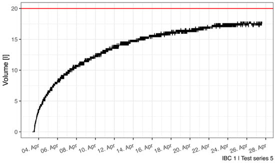
Figure 9.
Exemplary representation of the water output from the sand layer over time.
3.3. Institutional Framework and Cost-Benefit Analyzes
The results are divided into two key areas within the economic evaluation. Firstly, the institutional framework conditions for implementing the SPS were analyzed to identify potential enablers and barriers. Secondly, a CBA quantifies the economic viability of the system.
3.3.1. Institutions and Actor Analysis
The analysis of formal institutions focused on the federal state of North Rhine-Westphalia, as most formal institutions differ slightly in the various German federal states. In essence, the framework conditions that require the use of underground and above-ground areas for SPS were compiled. The degree of pollution of the rainwater discharged, the infiltration capacity of the soil and the absence of contaminated sites in the subsoil were also relevant. These factors are to be discussed with the lower water authority as part of an application for a water permit.
The analysis of the informal institutions began with the stakeholder analysis and a stakeholder survey. It was found that the information asymmetries between the organizations involved can best be reduced through transparency and widely available information. For example, there was a desire to transform construction requirements into the “Regeln der Technik” (state-of-the-art techniques) and to provide concrete planning aids.
3.3.2. Cost–Benefit Analysis and Financing
Stakeholders whose work is made more complicated by the increased considerations of water aspects like to use their information advantages in the sense of the principal-agent theory to nip measures such as SPS in the bud. A positive cost–benefit ratio is an important internal communication tool for the implementation of the SPS.
Compared with conventional drainage systems, the implementation of the SPS entails additional expenses, primarily due to higher construction and material costs. The increased material costs are mainly attributed to the cast-iron pipe, stone wool, and porous coarse-grained material. Furthermore, it is important to account for the costs associated with pre-cleaning road runoff, which may involve the use of a channel or filter shaft. Regarding construction costs, the primary factor is the larger excavation volume required to accommodate both the interface and the stone wool.
These additional costs were compared with the advantages of the SPS. First of all, these are the advantages that a tree site has over conventional drainage, such as an improved microclimate due to the increased cooling capacity [15] and the increase in biodiversity [83]. Compared with the currently common tree locations, a tree in the SPS is more vital due to the expanded root space, ventilation, and improved water supply, so that fewer costs are incurred for replacement planting. The storage of rainwater is also expected to significantly reduce irrigation costs. The high storage capacity of the system also leads to less damage from flooding. The summarized studies, which are applied using the benefit transfer method, suggest that the identified benefits will exceed the costs incurred in the medium term. However, they largely depend on the particular circumstances encountered in a region.
In particular, the expert interviews with the participating pilot municipalities showed the range of variation in financing. The primary question is the system category that is locally defined for the SPS. If it is primarily seen as a drainage system, the investment and operating costs can be financed via rainwater charges. Alternatively, the SPS could be declared as a hydrologically optimized tree site, which would involve investment costs for both the green spaces and the roads construction departments. The designation of SPS as a climate adaptation measure enables refinancing via the rainwater fee, the municipal budget, or subsidies.
3.4. Overview of the Pilot Projects in Leichlingen and Cologne
Stormwater network operatives and municipalities were involved in the BoRSiS project at an early stage. During the project, further municipalities joined to transfer knowledge into practice. These include the cities of Detmold, Leichlingen, Cologne, Wuppertal, and Solingen, as well as the Emschergenossenschaft water board. With the objective of implementing the SPS already in 2025, plans are underway in the cities of Detmold, Leichlingen, Cologne, and Wuppertal. The plans in the cities of Leichlingen, at the project site Friedensstraße, and in Cologne–Dellbrück, at the project site An der Kemperwiese (marketplace), are presented here.
3.4.1. Leichlingen, Friedensstraße Construction Project
On Friedensstraße in Leichlingen, a section of an existing concrete combined sewer system from the 1960s will be replaced with the SPS. This section, approximately 26 m in length, is located outside the street on municipal property. Additionally, the roof areas of the houses next to the street, which are also situated on municipal property and owned by the city, will be disconnected from the existent sewer network and redirected into the SPS. The system’s design at this site was adapted to account for the steeper gradient of the implementation area and incorporates a cascading arrangement of the stone wool elements. This configuration ensures efficient water conveyance and an enhanced retention capacity. The cascading arrangement also allows the stone wool to be installed relatively horizontally, preventing water from simply flowing through the stone wool along the slope and promoting gradual infiltration. Furthermore, the placement of the pipe under the pedestrian walkway introduces unique spatial and functional considerations. Trees are not positioned directly adjacent to the pipe trench but instead serve as separating elements between the cascading stone wool modules, effectively being part of the trench system. This arrangement still optimizes root growth within the trench, while also creating a spatial buffer. The thoughtful integration of trees as structural separators highlights the multifunctional nature of the SPS in urban landscapes, seamlessly balancing ecological and technical objectives.
3.4.2. Cologne, An der Kemperwiese (Marketplace)—Construction Project
As mentioned in Section 3.1 for Leichlingen, Cologne is also characterized by a temperate oceanic climate (Köppen–Geiger classification: Cfb) [81]. In the construction project “An der Kemperwiese (marketplace)” in the Dellbrück district of Cologne, a marketplace is being redesigned for multifunctional use. This includes interests to implement the blue–green infrastructure as part of Cologne’s “Water-Must-go-to-the-Tree” project. A total of 13 new trees will be planted in three rows on the market square, with planting pits designed as interconnected tree pits with a water infiltration function (Figure 10a). At the eastern edge of the square, the SPS will be installed as an extension, and one of the 13 trees will be connected to the SPS (Figure 10b). A unique aspect of this project is that it will enable performance monitoring of the SPS for the connected tree over several years. Moreover, since all 13 trees are being planted at the same time, their growth can be compared over time. This will demonstrate whether the tree connected to the SPS, which benefits from additional root space, shows increased vitality compared with the other trees.
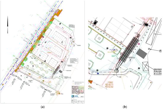
Figure 10.
Layout plans of the construction project “An der Kemperwiese (Marktplatz)” in Cologne–Dellbrück. (a) Overall view of the market square with the 13 new trees to be planted on the south side (green circles around black squares) and the soil-pipe system on the eastern edge of the three-row tree planting [84]; (b) Detail of the soil-pipe system with ductile iron pipe (in red) between the manholes 272443 and 10962, the 3 m × 12 m (w × l) stone wool elements (black grid), and the manholes and pipes for filling the stormwater storage system (in black) [84].
The draft design also includes a root zone with a width of 1.3 m and a height of approximately 1.0 m (green rectangle in Figure 10b between tree pit and stone wool). Above this, a stormwater reservoir made of stone wool elements measuring 3.0 m × 12.0 m × 1.0 m (w × l × h) will be installed. The connecting sewer from shaft 272443 to shaft 10692 will be constructed using ductile cast-iron pipes.
4. Discussion
The SPS was developed to address the key limitations of existing tree pit designs. While previous approaches, such as BC-Ts, structured soil substrates, and large-scale tree pits, have improved stormwater infiltration and soil aeration, they remain limited by spatial constraints, drought stress, insufficient root expansion, and waterlogging risks [30,34,35,36]. These challenges highlight the need for a multifunctional approach that optimally balances root growth, water retention, and urban infrastructure compatibility—the key objectives for which the SPS was designed.
Unlike sidewalk-integrated tree pits, which often compete with underground utility lines [40,41], the SPS repurposes pre-existing pipe trenches, reducing installation complexity and avoiding spatial conflicts. A fundamental requirement for implementing the SPS is to ensure its structural stability in the urban streetscape. The SPS utilizes stone wool elements, which were tested for their load-bearing capacity in urban environments. Initial applications of the system are implemented in residential areas with lower traffic volumes, where a minimum deformation modulus of Ev2 ≥ 45 MN/m2 is required by German road construction standards [49]. Geotechnical tests confirmed that the SPS, with a 0.3 m compacted sub-base layer, meets these requirements (Figure 3). However, since these tests were conducted under laboratory conditions, a thicker sub-base layer has been incorporated into the system sketch for real-world applications (Figure 1a). These results demonstrate that the SPS ensures sufficient road stability, enabling seamless integration into the existing infrastructure. By providing structural support, the stable stone wool elements also allow for the expansion of root space beneath them. This design overcomes the spatial limitations and excavation challenges commonly associated with conventional tree pits, making it a more efficient solution for dense urban environments. Beyond structural integration, hydrological performance is a critical factor for urban tree sites. Conventional tree pits frequently suffer from two issues: waterlogging due to insufficient drainage and inadequate long-term water availability, leading to unsustainable irrigation for trees [30,34,39]. The SPS circumvents these problems by spatially separating the water retention from the tree planting site. Instead of storing water directly at the planting location, the system retains water within the pipe trench above the expanded rooting zone. The SPS minimizes waterlogging risks while maintaining a stable moisture supply within the expanded rooting zone. This controlled release mechanism is particularly crucial in mitigating drought stress, a prevalent issue in urban environments.
To assess the effectiveness of the SPS system in mitigating drought stress, a systematic analysis was conducted. This analysis examined drought periods, precipitation events preceding dry spells, large-scale experimental trials on water availability over time (conducted in the Hydraulic Engineering Laboratory), tree water demand, and overall system performance. Climate data from the pilot municipalities indicate that 7-day and 14-day drought periods occur most frequently, with an annual frequency of 9 and 2 events, respectively. This underscores the necessity of a system that is capable of buffering recurring dry periods. To enable buffering through the SPS, precipitation data from pilot sites were evaluated to determine the average amount of rainfall preceding a drought period, thereby identifying the water available within the system during the drought period. The results indicate that in 50% of cases (median), 9.7 mm of rainfall occurs before a drought period. For a standard SPS module (a 20 m trench length, one connected tree, a total storage capacity of approximately 29,300 L, and a connected surface area of 530 m2), this equates to 5141 L of water that are available to the system. Large-scale experimental trials were conducted using this knowledge, revealing that approximately 20–25% of the rainfall is retained within the sand layer for up to 24 h. Given this volume, the system provides a buffer of 1028–1285 L of stored water. The large-scale experimental trials demonstrated a gradual release of stored water over 7–14 days (without trees), ensuring sustained moisture availability. The tree water demand varies depending on species, climate, and soil conditions, with an average daily requirement ranging from 50 to 300 L per tree [57,58,61]. Based on these parameters, the SPS can sustain trees for 3.4 to 25.7 days, significantly enhancing drought resilience compared with conventional tree pits, which primarily facilitate rapid infiltration rather than long-term water retention. Additionally, the role of stone wool elements in facilitating rapid water uptake was validated. Moreover, water infiltration from the root zone into the surrounding soil can further enhance storage potential, depending on site-specific conditions. A bypass overflow system is recommended where necessary to prevent excessive water accumulation and waterlogging. While these technical optimizations enhance system efficiency, the successful implementation also requires strong stakeholder collaboration and mutual respect. This includes interdisciplinary cooperation between urban planners, engineers, and ecologists to ensure the system’s optimal design and functionality. Early planning of exchange formats that raise awareness of urban water management challenges is essential. A best practice example is the Klima–Werk initiative in the Ruhr region, which brings together municipal representatives, experts, and planners to discuss urban water-related challenges. Regular meetings within this network foster improved collaboration and a heightened awareness of sustainable water management strategies.
While the initial findings confirm the feasibility of the SPS, continuous monitoring and further refinement are essential to facilitate widespread adoption and long-term sustainability. The SPS presents a promising tool for urban water management, yet its integration into existing planning frameworks and adaptation to future climatic challenges require further regulatory adjustments. Despite the SPS system’s effectiveness in reducing drought stress and retaining precipitation, several practical considerations must be addressed. Evaporation and increased transpiration during high-temperature periods were not included in the primary calculations but must be incorporated into long-term performance evaluations. Nonetheless, drought events lasting up to 14 days are well-buffered by the SPS, particularly in spring when the tree water demand is high, but extreme temperatures are less frequent. During this period, stored water remains available, further reducing drought stress. Additionally, the SPS system mitigates surface runoff, thereby reducing the burden on the urban drainage infrastructure through efficient water retention. However, prolonged droughts may exceed the system’s capacity, necessitating supplemental irrigation. As part of a broader BGI strategy, the SPS should be integrated with additional adaptation measures to enhance urban resilience. Its adaptability has been demonstrated in pilot cities, such as Leichlingen and Cologne, where site-specific modifications optimized performance. Future research should investigate long-term water storage efficiency, regulatory integration, and regional climate variations to further enhance the system functionality.
5. Conclusions
This study introduces the SPS as a novel, multifunctional approach to urban stormwater management and climate adaptation, addressing research gaps in the BGI. Unlike conventional tree pit systems, which are often constrained by spatial limitations and hydrological inefficiencies, the SPS utilizes existing underground pipe trenches to expand the root space and water storage capacity without competing for additional urban land, making it a practical and scalable solution for dense urban environments. The SPS provides structural stability, ensuring that the system can be implemented effectively and remains compatible with the existing infrastructure. In addition, its advanced water retention and controlled release mechanisms enhance tree vitality, mitigate flood risks, and improve overall stormwater management. Data analyses and experimental trials demonstrated that each SPS module (20 m trench) can store an average of 1028–1285 L of water, enabling drought buffering for 3.4 to 25.7 days, depending on the species and site conditions. Climate data from pilot sites show that 7- and 14-day drought periods occur with annual frequencies of 9 and 2, respectively—periods that the system can effectively buffer. These quantified results demonstrate the SPS added value over conventional tree pits, which typically cannot retain water long enough to buffer such events. An advantage of the SPS is its separation of water retention from the immediate planting site, which prevents waterlogging and ensures sustained moisture availability during drought periods. Unlike conventional tree pits that either retain excessive water or drain quickly, the SPS effectively balances infiltration and storage, demonstrating improved efficiency in both retention duration and drought resilience. Additionally, by alleviating the pressure on urban drainage systems and reducing runoff peaks during extreme precipitation events, the SPS contributes significantly to urban climate resilience. Its design as a linear system allows for efficient water distribution, while the high storage capacity of the stone wool component enables the temporary retention of large rainfall volumes. Its multifunctional design enables urban trees to provide long-term ecosystem services, including urban cooling, air quality improvement, and flood mitigation, further strengthening the city-wide adaptation to climate change. The practical viability and scalability of the SPS were demonstrated in pilot municipalities involved in the BoRSiS project. These pilot projects provided valuable insights on the system implementation, stakeholder coordination, and cost-effective integration into urban planning. The ability to leverage “windows of opportunity”, such as aligning the SPS installation with planned infrastructure projects, has proven to be a key driver in reducing costs, improving public acceptance, and accelerating adoption. However, despite its promising performance, certain challenges remain that require further investigation.
While initial findings confirm the system’s feasibility in residential areas with low traffic volumes, further research is needed to assess its long-term performance. Additionally, its transferability to diverse urban settings also with high-traffic conditions and different climatic regions should be evaluated, as variations in precipitation patterns, soil permeability, and evaporation rates may impact the system’s efficiency. Certain environmental factors, such as high groundwater tables, could limit the system’s retention capacity, while steep road gradients may complicate water retention and controlled release functions. From an infrastructure and implementation perspective, scaling the SPS presents additional technical and regulatory challenges. As the system relies on pre-existing pipe trenches and cast-iron pipes, its widespread adoption depends on the integration into ongoing urban development or redevelopment projects. Future studies should explore opportunities for optimization, particularly in enhancing cost-efficiency, refining installation techniques, and adapting the system for broader climate resilience strategies.
By bridging the gap between urban tree-root expansion, stormwater retention, and infrastructure integration, the SPS represents a scalable, nature-based solution that enhances the BGI for climate-resilient cities. The knowledge gained from pilot implementations provides a solid foundation for future research, allowing for the continuous refinement and adaptation of the system. Moving forward, collaborative research efforts, cross-sector partnerships, and real-world applications will be crucial to unlocking the full potential of the SPS as a key component of sustainable urban water management strategies.
Author Contributions
Conceptualization, H.W., M.Q., and C.B.; methodology, H.W., M.Q., M.O., C.M., D.J.B., and C.B.; software, H.W., F.S., and D.J.B.; formal analysis, H.W., F.S., and D.J.B.; investigation, H.W., F.S., S.S., and D.J.B.; resources, C.B. and D.J.B.; data curation, H.W.; writing—original draft preparation, H.W., M.Q., C.B., D.J.B., F.S., C.M., M.O., S.S., and M.S.; writing—review and editing, H.W. and M.Q.; visualization, H.W.; supervision, M.Q.; project administration, M.Q.; funding acquisition, M.Q., C.M., and C.B. All authors have read and agreed to the published version of the manuscript.
Funding
This research work is part of the research project “BoRSiS–Boden-Rohr-System als innovatives Element der klimaangepassten Stadtentwässerung” (soil-pipe system as an innovative element of climate-adapted urban drainage) funded by the Federal Ministry of Education and Research (BMBF), Germany (grant number 13FH002KA0).
Data Availability Statement
The climate data utilized in this study are sourced from the publicly accessible HYRAS dataset provided by the German Weather Service (DWD). HYRAS is a high-resolution gridded dataset specifically developed for hydrological research in Germany, offering comprehensive precipitation and climate data across multiple timeframes. The test data generated during this research are part of ongoing studies and are therefore not publicly available at this time. These data include results from laboratory experiments and field tests conducted as part of the project. They will be made accessible upon the completion and publication of the associated research.
Acknowledgments
The authors would like to express their gratitude to all the project partners for their invaluable support and collaboration. Special thanks go to the cities of Detmold, Leichlingen, Cologne, Bochum, Solingen, and Wuppertal, as well as the Emschergenossenschaft water board, for their professional expertise and cooperation in the pilot areas. Their contributions were essential to the successful implementation and progress of this research.
Conflicts of Interest
Author Dirk Jan Boudeling was employed by the company Rockflow Rainwater Systems. Author Christoph Bennerscheidt was employed by the company European Associations of Ductile Iron Pipe Systems. The remaining authors declare that the research was conducted in the absence of any commercial or financial relationships that could be construed as a potential conflict of interest.
References
- Liao, K.-H.; Deng, S.; Tan, P.Y. Blue-Green Infrastructure: New Frontier for Sustainable Urban Stormwater Management. In Advances in 21st Century Human Settlements; Springer: Singapore, 2017; pp. 203–226. [Google Scholar] [CrossRef]
- Douglas, I.; Anderson, P.M.L.; Goode, D.; Houck, M.C.; Maddox, D.; Nagendra, H.; Tan, P.Y. The Routledge Handbook of Urban Ecology, 2nd ed.; Routledge Taylor & Francis Group: London, UK; New York, NY, USA, 2021; ISBN 9781138581357. [Google Scholar]
- Richter, M.; Heinemann, K.; Meiser, N.; Dickhaut, W. Trees in Sponge Cities—A Systematic Review of Trees as a Component of Blue-Green Infrastructure, Vegetation Engineering Principles, and Stormwater Management. Water 2024, 16, 655. [Google Scholar] [CrossRef]
- Berland, A.; Shiflett, S.A.; Shuster, W.D.; Garmestani, A.S.; Goddard, H.C.; Herrmann, D.L.; Hopton, M.E. The role of trees in urban stormwater management. Landsc. Urban Plan. 2017, 162, 167–177. [Google Scholar] [CrossRef] [PubMed]
- Fletcher, T.D.; Shuster, W.; Hunt, W.F.; Ashley, R.; Butler, D.; Arthur, S.; Trowsdale, S.; Barraud, S.; Semadeni-Davies, A.; Bertrand-Krajewski, J.-L.; et al. SUDS, LID, BMPs, WSUD and more—The evolution and application of terminology surrounding urban drainage. Urban Water J. 2015, 12, 525–542. [Google Scholar] [CrossRef]
- European Commission. Green and Blue Infrastructures. Available online: https://knowledge4policy.ec.europa.eu/glossary-item/green-blue-infrastructures_en?utm (accessed on 13 February 2025).
- Pauleit, S.; Duhme, F. Assessing the environmental performance of land cover types for urban planning. Landsc. Urban Plan. 2000, 52, 1–20. [Google Scholar] [CrossRef]
- Wong, T.H.F.; Brown, R.R. The water sensitive city: Principles for practice. Water Sci. Technol. 2009, 60, 673–682. [Google Scholar] [CrossRef]
- Livesley, S.J.; McPherson, G.M.; Calfapietra, C. The Urban Forest and Ecosystem Services: Impacts on Urban Water, Heat, and Pollution Cycles at the Tree, Street, and City Scale. J. Environ. Qual. 2016, 45, 119–124. [Google Scholar] [CrossRef]
- Pataki, D.E.; Alberti, M.; Cadenasso, M.L.; Felson, A.J.; McDonnell, M.J.; Pincetl, S.; Pouyat, R.V.; Setälä, H.; Whitlow, T.H. The Benefits and Limits of Urban Tree Planting for Environmental and Human Health. Front. Ecol. Evol. 2021, 9, 603757. [Google Scholar] [CrossRef]
- Zheng, S.; He, C.; Guldmann, J.-M.; Xu, H.; Liu, X. Heat Mitigation Benefits of Urban Trees: A Review of Mechanisms, Modeling, Validation and Simulation. Forests 2023, 14, 2280. [Google Scholar] [CrossRef]
- Hatfield, J.L.; Dold, C. Water-Use Efficiency: Advances and Challenges in a Changing Climate. Front. Plant Sci. 2019, 10, 103. [Google Scholar] [CrossRef]
- Watson, G.W. The Landscape Below Ground IV: Proceedings of the Fourth International Workshop on Tree Root Development in Urban Soils; International Society of Arboriculture: Atlanta, Georgia, 2020; ISBN 9781943378074. [Google Scholar]
- Miesbauer, J.W. Landscape Below Ground V: Introduction to a Special Issue. Arboric. Urban For. 2025, 51, 1–2. [Google Scholar] [CrossRef]
- Gillner, S.; Vogt, J.; Tharang, A.; Dettmann, S.; Roloff, A. Role of street trees in mitigating effects of heat and drought at highly sealed urban sites. Landsc. Urban Plan. 2015, 143, 33–42. [Google Scholar] [CrossRef]
- Czaja, M.; Kołton, A.; Muras, P. The Complex Issue of Urban Trees—Stress Factor Accumulation and Ecological Service Possibilities. Forests 2020, 11, 932. [Google Scholar] [CrossRef]
- Rahman, M.A.; Armson, D.; Ennos, A.R. A comparison of the growth and cooling effectiveness of five commonly planted urban tree species. Urban Ecosyst. 2015, 18, 371–389. [Google Scholar] [CrossRef]
- Lindsey, P.; Bassuk, N. Redesigning the urban forest from the ground below: A new approach to specifying adequate soil volumes for street trees. Arboric. J. 1992, 16, 25–39. [Google Scholar] [CrossRef]
- Egerer, M.; Schmack, J.M.; Vega, K.; Barona, C.O.; Raum, S. The challenges of urban street trees and how to overcome them. Front. Sustain. Cities 2024, 6, 1394056. [Google Scholar] [CrossRef]
- GreenBlue Urban. Soil Requirements of Healthy Urban Trees. Available online: https://greenblue.com/wp-content/uploads/2019/09/Soil-Requirements-of-Healthy-Urban-Trees-eBook-2019.pdf (accessed on 16 February 2025).
- Gillner, S.; Vogt, J.; Roloff, A. Climatic response and impacts of drought on oaks at urban and forest sites. Urban For. Urban Green. 2013, 12, 597–605. [Google Scholar] [CrossRef]
- Layman, R.M.; Day, S.D.; Mitchell, D.K.; Chen, Y.; Harris, J.R.; Daniels, W.L. Below ground matters: Urban soil rehabilitation increases tree canopy and speeds establishment. Urban For. Urban Green. 2016, 16, 25–35. [Google Scholar] [CrossRef]
- Rahman, M.A.; Pawijit, Y.; Xu, C.; Moser-Reischl, A.; Pretzsch, H.; Rötzer, T.; Pauleit, S. A comparative analysis of urban forests for storm-water management. Sci. Rep. 2023, 13, 1451. [Google Scholar] [CrossRef]
- Grey, V.; Livesley, S.J.; Fletcher, T.D.; Szota, C. Tree pits to help mitigate runoff in dense urban areas. J. Hydrol. 2018, 565, 400–410. [Google Scholar] [CrossRef]
- Embren, B. Urban Trees and Stormwater Management in Stockholm: A Sustainable Solution, Trees and Design Action Group. United Kingdom. 2015. Available online: https://coilink.org/20.500.12592/ccksnb (accessed on 6 May 2025).
- Elliott, R.M.; Adkins, E.R.; Culligan, P.J.; Palmer, M.I. Stormwater infiltration capacity of street tree pits: Quantifying the influence of different design and management strategies in New York City. Ecol. Eng. 2018, 111, 157–166. [Google Scholar] [CrossRef]
- Frosi, M.H. Street Tree Pits as Bioretention Units: Analysis of Their Performance in a Residential Area of Montreal, Canada; McGill University: Montreal, QC, Canada, 2019. [Google Scholar]
- Dickhaut, W.; Richter, M. Decentralized Stormwater Management: Experiences with Various Measures in Germany; Wang, F., Prominski, M., Eds.; Springer: Singapore, 2020. [Google Scholar]
- Li, H.; Ding, L.; Ren, M.; Li, C.; Wang, H. Sponge City Construction in China: A Survey of the Challenges and Opportunities. Water 2017, 9, 594. [Google Scholar] [CrossRef]
- Siering, N.; Grüning, H. Stormwater Tree Pits for Decentralized Retention of Heavy Rainfall. Water 2023, 15, 2987. [Google Scholar] [CrossRef]
- Embrén, B. Plant Beds in Stockholm City: A Handbook. 2017. Available online: https://www.biochar.info/docs/urban/Planting_beds_in_Stockholm_2017.pdf (accessed on 21 February 2022).
- Novak, L.; Kabelkova, I.; Hora, D.; Stransky, D. Optimization of a Tree Pit as a Blue–Green Infrastructure Object. Sustainability 2023, 15, 15731. [Google Scholar] [CrossRef]
- Bell, D.L.; Doick, K.J.; Sinnett, D.E. The role of engineered tree pit solutions in nature-positive civil engineering. Proc. Inst. Civ. Eng.—Civ. Eng. 2024, 1–12. [Google Scholar] [CrossRef]
- Gartenamtsleiterkonferenz; Vereinigung Schweizerischer Stadtgärtnereien und Gartenbauämter. Positionspapier: Einsatz von Streusalz—Konsequenzen für Straßenbäume. Available online: https://www.galk.de/startseite/downloads/?task=download.send&id=823:flyer-positionspapier-streusalz-2022&catid=3 (accessed on 20 October 2024).
- Shi, F.; Meng, Q.; Pan, L.; Wang, J. Key factors influencing street tree root conflicts with planting pits and sidewalks in old Guangzhou, China. Urban For. Urban Green. 2024, 101, 128538. [Google Scholar] [CrossRef]
- Bell, D.L. The Impact of Engineered Tree Pit Solutions on Street Tree Growth and Survival. Doctoral Dissertation, University of the West of England, Bristol, UK, 2024. [Google Scholar]
- Mullaney, J.; Lucke, T.; Trueman, S.J. A review of benefits and challenges in growing street trees in paved urban environments. Landsc. Urban Plan. 2015, 134, 157–166. [Google Scholar] [CrossRef]
- Nazarpour, S.; Gnecco, I.; Palla, A. Evaluating the Effectiveness of Bioretention Cells for Urban Stormwater Management: A Systematic Review. Water 2023, 15, 913. [Google Scholar] [CrossRef]
- Thom, J.K.; Fletcher, T.D.; Livesley, S.J.; Grey, V.; Szota, C. Supporting Growth and Transpiration of Newly Planted Street Trees With Passive Irrigation Systems. Water Resour. Res. 2022, 58, 1. [Google Scholar] [CrossRef]
- Smiley, E.T. Comparison of Methods to Reduce Sidewalk Damage from Tree Roots. AUF 2008, 34, 179–183. [Google Scholar] [CrossRef]
- Randrup, T.B.; McPherson, E.G.; Costello, L.R. A review of tree root conflicts with sidewalks, curbs, and roads. Urban Ecosyst. 2001, 5, 209–225. [Google Scholar] [CrossRef]
- Forschungsgesellschaft Landschaftsentwicklung Landschaftsbau e.V. Empfehlungen für Baumpflanzungen: Teil 2: Standortvorbereitungen für Neupflanzungen; Pflanzgruben und Wurzelraumerweiterung, Bauweisen und Substrate; Forschungsgesellschaft Landschaftsentwicklung Landschaftsbau eV: Bonn, Germany, 2010. [Google Scholar]
- Grabosky, J.; Bassuk, N. A New Urban Tree Soil to Safely Increase Rooting Volumes Under Sidewalks. AUF 1995, 21, 187–201. [Google Scholar] [CrossRef]
- Walther, H.; Bennerscheidt, C.; Quirmbach, M.; Boudeling, D.-J.; Streckenbach, M. (Eds.) Mehr Raum für Regenwasser und Baumwurzeln im Straßenraum: Das Boden-Rohr-System zur Anpassung von Städten an den Klimawandel; Aqua Urbanica: Graz, Austria, 2024. [Google Scholar]
- Schmiege, S.C.; Heskel, M.; Fan, Y.; Way, D.A. It’s only natural: Plant respiration in unmanaged systems. Plant Physiol. 2023, 192, 710–727. [Google Scholar] [CrossRef] [PubMed]
- Rockwool. Design and Build: All Tools for a Successful Rockflow System in One Place. Available online: https://rain.rockwool.com/uk/design-and-install/ (accessed on 15 January 2025).
- Forschungsgesellschaft für Straßen- und Verkehrswesen. RStO 12: Richtlinien für die Standardisierung des Oberbaus von Verkehrsflächen. Available online: https://www.fgsv-verlag.de/rsto (accessed on 25 April 2023).
- DIN 18134:2012-04; Baugrund—Versuche und Versuchsgeräte—Plattendruckversuch. DIN Media GmbH: Berlin, Germany, 2012.
- Floss, R. Handbuch ZTV E-StB; Kirschbaum Verlag: Bonn, Germany, 2019. [Google Scholar]
- European Association for Ductile Iron Pipe Systems. Cast Iron Pipes Manual of the European Association of Ductile Iron Pipe Systems. Available online: https://en.eadips.org/manual-cast-iron-pipe-systems/ (accessed on 17 October 2024).
- EN 598:2009-10; Ductile Iron Pipes, Fittings, Accessories and Their Joints for Sewerage Applications—Requirements and Test Methods. DIN Media GmbH: Berlin, Germany, 2009.
- EN 15542:2021; Ductile Iron Pipes, Fittings and Accessories—External Cement Mortar Coating for Pipes—Requirements and Test Methods. DIN Media GmbH: Berlin, Germany, 2021.
- DIN EN 17970:2024-08; Ductile Iron Pipes—Push-in Joints for Ductile Iron Pipe Systems—Resistance Against Root Penetration—Requirements and Test Methods. DIN Media GmbH: Berlin, Germany, 2024.
- Deutscher Wetterdienst. HYRAS—Hydrometeorologischer Rasterdatensatz. Available online: https://www.dwd.de/DE/leistungen/hyras/hyras.html?nn=16102&lsbId=499730 (accessed on 22 October 2024).
- de Martonne, E. Une nouvelle fonction climatologique: L’indice d’aridité. La Météorologie. Meteorologie 1926, 2, 449–458. [Google Scholar]
- Nisbet, T. Forestry Commission Information Note: Water Use by Trees; Forestry Commission: Edinburgh, UK, 2005; ISBN 0-85538-654-1. [Google Scholar]
- Wullschleger, S.D.; Hanson, P.J.; Tschaplinski, T.J. Whole-plant water flux in understory red maple exposed to altered precipitation regimes. Tree Physiol. 1998, 18, 71–79. [Google Scholar] [CrossRef] [PubMed]
- Wullschleger, S.D.; Meinzer, F.C.; Vertessy, R.A. A review of whole-plant water use studies in tree. Tree Physiol. 1998, 18, 499–512. [Google Scholar] [CrossRef]
- Kendzia, N. Bewässern Nach Regeln—Wasserbedarf urbaner Grünflächen: Beratungsblatt, 1st ed.; Arbeitsgemeinschaft Landtechnik und Landwirtschaftliches Bauwesen in Bayern e.V. (ALB): Freisingen, Germany, 2020. [Google Scholar]
- Deutsches Institut für Normung e, V. DIN 18919 | 2016-12: Vegetationstechnik im Landschaftsbau—Instandhaltungsleistungen für die Entwicklung und Unterhaltung von Vegetation (Entwicklungs- und Unterhaltungspflege). Available online: https://www.baunormenlexikon.de/norm/din-18919/93cab356-0c19-426f-af30-433a7512fac7 (accessed on 10 October 2024).
- Matyssek, R.; Fromm, J.; Rennenberg, H.; Roloff, A. Biologie der Bäume: Von der Zelle zur Globalen Ebene; Verlag Eugen Ulmer; UTB: Stuttgart, Germany, 2010; ISBN 978-3-8001-2840-2. [Google Scholar]
- Deutsche Vereinigung für Wasserwirtschaft. Abwasser und Abfall. Arbeitsblatt DWA-A 118: Bewertung der Hydraulischen Leistungsfähigkeit von Entwässerungssystemen; Deutsche Vereinigung für Wasserwirtschaft: Hennef, Germany, 2024; ISBN 9783968626581. [Google Scholar]
- openko.de. KOSTRA-DWD-2020: Öffentlich zugängliche Tabelle basierend auf den Daten des KOSTRA-DWD-2020 Atlas. Available online: https://www.openko.de/ (accessed on 16 August 2024).
- Deutsche Vereinigung für Wasserwirtschaft. Abwasser und Abfall. Arbeitsblatt DWA-A 138-1: Anlagen zur Versickerung von Niederschlagwasser Teil 1: Planung, Bau, Betrieb; Deutsche Vereinigung für Wasserwirtschaft: Hennef, Germany, 2024. [Google Scholar]
- Erlei, M.; Leschke, M.; Sauerland, D. Neue Institutionenökonomik; Schäffer Poeschel Verlag: Stuttgart, Germany, 2007; ISBN 9783791022963. [Google Scholar]
- Rogall, H. Volkswirtschaftslehre für Sozialwissenschaftler: Eine Einführung; VS Verlag für Sozialwissenschaften/GWV Fachverlage GmbH: Wiesbaden, Germany, 2006; ISBN 978-3-531-14538-9. [Google Scholar]
- Simon, H.A. Administrative Behavior: A Study of Decision-Making Processes in Administrative Organization; Free Press: New York, NY, USA, 1976. [Google Scholar]
- Blum, U.; Dudley, L.; Leibbrand, F.; Weiske, A. Angewandte Institutionenökonomik: Theorien, Modelle, Evidenz; Gabler Verlag: Wiesbaden, Germany, 2005; ISBN 978-3-409-14273-1. [Google Scholar]
- Grimble, R.; Wellard, K. Stakeholder methodologies in natural resource management: A review of principles, contexts, experiences and opportunities. Agric. Syst. 1997, 55, 173–193. [Google Scholar] [CrossRef]
- Project Management Institute, Inc. A Guide to the Project Management Body of Knowledge: (PMBOK Guide); Project Management Institute, Inc.: Newtown Square, PA, USA, 2008. [Google Scholar]
- Tiemeyer, E. Projektumfeldanalyse—Stakeholdermanagement. In Projektmanagement: Handbuch für die Praxis; Konzepte—Instrumente—Umsetzung; Litke, H.-D., Ed.; Hanser: München, Germany, 2005; pp. 622–639. ISBN 9783446229075. [Google Scholar]
- Lienert, J.; Schnetzer, F.; Ingold, K. Stakeholder analysis combined with social network analysis provides fine-grained insights into water infrastructure planning processes. J. Environ. Manag. 2013, 125, 134–148. [Google Scholar] [CrossRef]
- Trapp, J.H.; Stieß, I.; Nenz, D. Akteure der Planungsprozesse. In Blau-Grün-Graue Infrastrukturen Vernetzt Planen und Umsetzen; Trapp, J.H., Winker, M., Eds.; Deutsches Institut für Urbanistik gGmbH: Berlin, Germany, 2020; pp. 109–113. ISBN 978-3-88118-660-5. [Google Scholar]
- Landesamt für Natur, Umwelt und Verbraucherschutz Nordrhein-Westfalen. Dezentrale Niederschlagswasserbehandlung in Trennsystemen: Umsetzung des Trennerlasses. Abschlussbericht des Forschungsprojekts—Kurzfassung; Landesamt für Natur, Umwelt und Verbraucherschutz Nordrhein-Westfalen: Recklinghausen, Germany, 2011. [Google Scholar]
- Ward, F.A. Cost–benefit and water resources policy: A survey. Water Policy 2012, 14, 250–280. [Google Scholar] [CrossRef]
- Grothmann, T.; Denhardt, A.; Wagner, J.; Welling, M. Kosten-Nutzen-Analysen in der Klimaanpassungs- Planung und -Politik: Wofür Sie Nutzbar Sind und Was für ihre Nutzbarkeit Wichtig Ist. BREsilient, 2021. Available online: https://bresilient.de/wp-content/uploads/2021/03/BREsilient-Bericht_Kosten-Nutzen-Analysen_Nutzbarkeit_in_Klimaanpassungspolitik.pdf (accessed on 16 February 2022).
- Holländer, R.; Ammermüller, B.; Fälsch, M.; Klauer, B.; Sigel, K.; Mewes, M.; Bräuer, I.; Grüning, M.; Ehlers, M. Entwicklung Einer Methodik zur Nicht-Monetären Kosten-Nutzen- Abwägung im Umsetzungsprozess der EG-Wasserrahmenrichtlinie. Abschlussbericht, 2008. Available online: https://www.flussgebiete.nrw.de/system/files/atoms/files/abschlussbericht-kosten-nutzen-2008.pdf (accessed on 1 March 2022).
- Hanley, N.; Spash, C.L. Cost–Benefit Analysis and the Environment 1993. Available online: https://www.e-elgar.com/shop/gbp/cost-benefit-analysis-and-the-environment-9781852789473.html?srsltid=AfmBOorJqPKj6oIpz1n1UsWVG0gyMRqiU_k6rFDhHXdfn3LyRAeqBFLh (accessed on 4 March 2022).
- Marggraf, R.; Streb, S. Ökonomische Bewertung der Natürlichen Umwelt; Spektrum Akademischer Verlag: Heidelberg, Germany, 1997. [Google Scholar]
- Rosenberger, R.S.; Loomis, J.B. Benefit Transfer. In A Primer on Nonmarket Valuation, 2nd ed.; Champ, P.A., Boyle, K.J., Brown, T.C., Eds.; Springer: Dordrecht, The Netherlands, 2017; pp. 431–462. ISBN 978-94-007-7103-1. [Google Scholar]
- Beck, H.E.; Zimmermann, N.E.; McVicar, T.R.; Vergopolan, N.; Berg, A.; Wood, E.F. Present and future Köppen-Geiger climate classification maps at 1-km resolution. Sci. Data 2018, 5, 180214. [Google Scholar] [CrossRef]
- Forner, A.; Valladares, F.; Bonal, D.; Granier, A.; Grossiord, C.; Aranda, I. Extreme droughts affecting Mediterranean tree species’ growth and water-use efficiency: The importance of timing. Tree Physiol. 2018, 38, 1127–1137. [Google Scholar] [CrossRef]
- Ronchi, S.; Scholz, T.; Hof, A. Ökosystemdienstleistungen von Stadtbäumen in urban-industriellen Stadtlandschaften: Analyse, Bewertung und Kartierung mit Baumkatastern. J. Für Angew. Geoinformatik 2016, 2, 462–471. [Google Scholar]
- Elis, K. Pilot Project of StEB Cologne for BoRSiS: Marketplace “An der Kemperwiese” in Cologne-Dellbrück; Cologne Municipal Drainage Authority: Mülheim an der Ruhr, Germany, 2024. [Google Scholar]
Disclaimer/Publisher’s Note: The statements, opinions and data contained in all publications are solely those of the individual author(s) and contributor(s) and not of MDPI and/or the editor(s). MDPI and/or the editor(s) disclaim responsibility for any injury to people or property resulting from any ideas, methods, instructions or products referred to in the content. |
© 2025 by the authors. Licensee MDPI, Basel, Switzerland. This article is an open access article distributed under the terms and conditions of the Creative Commons Attribution (CC BY) license (https://creativecommons.org/licenses/by/4.0/).