Article

Analytical Solution for Water Inflow into Deeply Buried Symmetrical Subsea Tunnels with Excavation Damage Zones

1
College of Harbour and Coastal Engineering, Jimei University, Xiamen 361021, China
2
State Key Laboratory of Hydraulic Engineering Simulation and Safety, Tianjin University, Tianjin 300072, China
3
Hunan Provincial Key Laboratory of Geotechnical Engineering for Stability Control and Health Monitoring, School of Civil Engineering, Hunan University of Science and Technology, Xiangtan 411100, China
*
Author to whom correspondence should be addressed.
Water 2023, 15(20), 3556; https://doi.org/10.3390/w15203556
Submission received: 6 September 2023 / Revised: 28 September 2023 / Accepted: 9 October 2023 / Published: 12 October 2023

Abstract

:
The water inflow into tunnels will vary with the development of excavation damage zones (EDZs). Currently, there are few analytical studies on the evaluation of the water inflow into deeply buried symmetrical subsea tunnels, considering the influence of EDZs. Therefore, a solution was analytically developed using seepage mechanics, conformal mappings, and the superposition principle. The proposed solution was verified with a simplified solution and a numerical solution. A range of parametric analyses were performed to determine the effects of EDZs and spatial parameters on the water inflow, and an application to an engineering case was carried out. The results in this study reveal that the relative error between the proposed solution and the numerical solution is always less than 2.5% when the ratio of the buried depth to the radius of the tunnel is greater than or equal to 4. The water inflow increases significantly at an early stage of increasing the EDZ permeability coefficient, then gradually stabilizes and increases approximately linearly with the EDZ thickness. The effects of EDZs are greater with smaller buried depths and greater distances between the two tunnel centres. Compared with a single subsea tunnel, there is a diverting effect between the symmetrical subsea tunnels, which can be promoted by increasing the EDZ parameters. Moreover, this diverting effect increases as the buried depth increases and the distance between the two tunnel centres decreases. The application in this study shows that an increase of 13.82% to 30.42% in the water inflow occurred after considering the EDZs’ effects. The proposed solution can provide an efficient method to evaluate the water inflow into the deeply buried symmetrical subsea tunnels with EDZs.

1. Introduction

The technology and the number of subsea tunnels have dramatically developed in recent decades [1,2,3]. For instance, numerous subsea tunnels have been constructed in Chinese coastal cities, such as the Xiamen Haicang Tunnel, the Qingdao Jiaozhou Bay Tunnel, and the Dalian Bay Tunnel [4,5]. Scientific assessments of the water inflow are critical but arduous for subsea tunnels [6,7]. Due to the unlimited water supply above subsea tunnels, inaccurate predictions of the water inflow can lead to severe water ingress disasters or an overly conservative design of the drainage system [8,9,10,11]. Hence, considerable efforts have been devoted to water inflow assessments that employ analytical [12,13,14,15,16,17,18,19,20,21,22,23,24,25,26,27], empirical [28,29], and numerical [30,31,32] methods.
As the most common method for predicting the water inflow into tunnels, analytical solutions are convenient, reliable, and cost-effective. In recent years, many analytical solutions have been proposed for various conditions, using different types of methods, such as the image method [12,13,14,15,16], conformal mappings [17,18,19,20,21,22,23], and other methods [24,25,26,27]. Several analytical studies have been carried out on the seepage field of symmetrical underwater tunnels. Qin et al. [14] and Wang et al. [15] developed analytical models for the seepage field of symmetrical subsea tunnels based on the mirror image method and the superposition principle. Zhang [16] derived an analytical solution for the steady seepage field of twin parallel tunnels in a semi-infinite plane based on the mirror image method and the theory of seepage mechanics. Guo et al. [17] presented an analytical solution of the seepage field for underwater twin parallel tunnels using the Schwartz alternating method combined with conformal mappings. Zhu et al. [18] obtained analytical solutions for the seepage field of underwater twin parallel tunnels using conformal mappings and the method of superposition.
An excavation damage zone normally exists around various engineering structures excavated underground such as tunnels [24,33]. The results of extensive studies have shown that the evolution of EDZs is characterized by changes in fractures, and varying degrees of EDZ permeability have been reported in numerous field tests [34,35,36,37]. As a result, the EDZs provide easier access to seepage and will lead to more water inflow into tunnels. For an underwater single-hole tunnel, Pan et al. [8] performed a comparative study using analytical and numerical methods to investigate the influence of EDZs on the water inflow. When compared with a single-hole tunnel, the seepage in symmetrical subsea tunnels with EDZs is more complicated and the corresponding changing patterns of water inflow with EDZ parameters urgently needs to be clarified.
However, it is worth noting that the analytical methods for the water inflow assessments of the symmetrical subsea tunnels with EDZs have rarely been considered in previous studies, and it is useful for the design, construction, and operation of the symmetrical subsea tunnels to derive an analytical solution for this situation. In this study, the goal is to propose an analytical solution to assess the water inflow into the symmetrical subsea tunnels with EDZs. To achieve the above objective, this work employed seepage mechanics, conformal mappings, and the superposition principle to perform a theoretical derivation, and the presented solution was confirmed by comparisons with a simplified analytical solution from the literature and a numerical solution. By means of this developed solution, the effects of EDZs and spatial parameters on the water inflow were analysed. The differences between the water inflow into a single subsea tunnel and into the symmetrical subsea tunnels, while taking EDZs into account, were discussed, and the application to an engineering case was carried out.

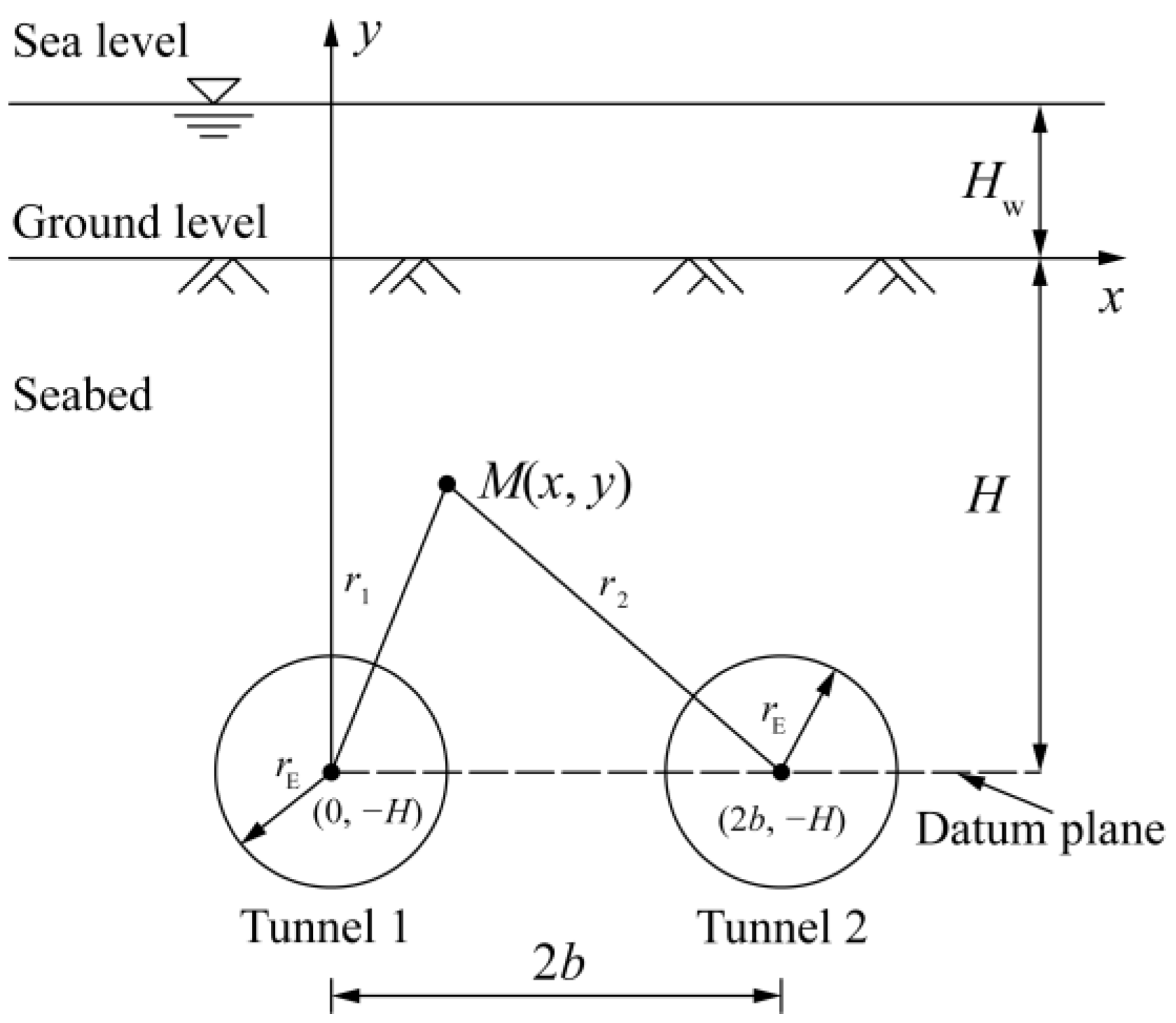
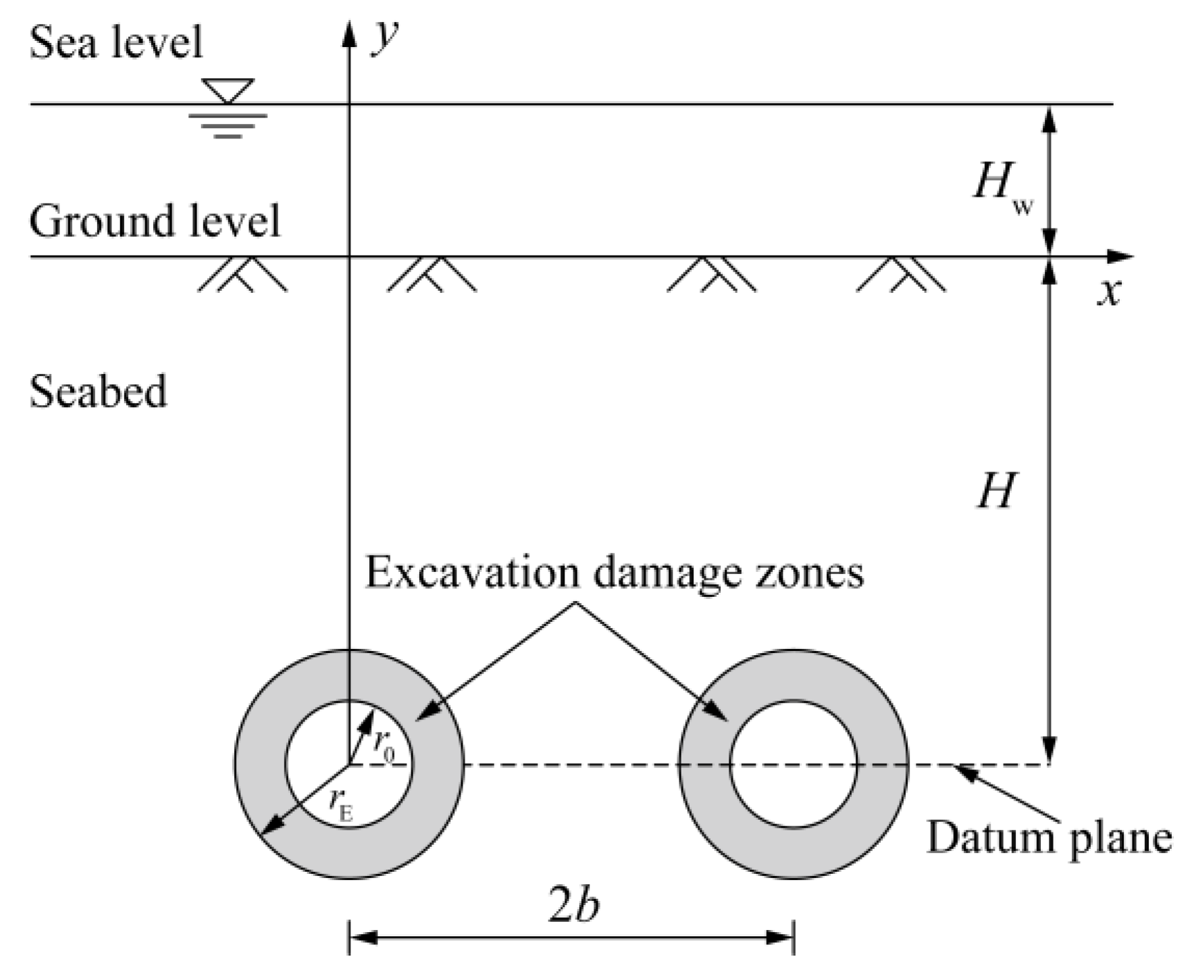
2. Problem Description

2.1. Theoretical Model and Assumptions

Figure 1 shows that the symmetrical subsea tunnels with EDZs are deeply buried in a seabed and that the sea level is horizontal and stable in this theoretical model. The parameters r 0 and r E represent the radii of tunnels and the radii of tunnels with EDZs, respectively. The distance from the sea level to the ground level is H w . The distance from the ground level to the tunnel centre is H. The distance between the two tunnel centres is 2b. The dotted line in Figure 1 is chosen as the datum plane.
The assumptions are summarized as follows:
(1)
The seabed and EDZs are saturated, homogeneous, and isotropic.
(2)
The subsea tunnels are circular and symmetrical. The radii of tunnels with EDZs are far smaller than H, namely, H > > r E . Hence, the groundwater flows into the tunnels along the radial direction [4,26].
(3)
A steady and incompressible flow, which obeys Darcy’s law, is employed in this model. The hydraulic heads on the circumference of the tunnels and the EDZs are constant.

2.2. Governing Equation and Boundary Conditions

The two-dimensional stable seepage through a saturated, homogeneous, and isotropic medium is dominated by the equation below:
2 h x 2 + 2 h y 2 = 0
h = p γ w + y + H
where h is the hydraulic head, p is the water pressure, and γ w is the unit weight of water.
Furthermore, five boundary conditions (BCs) are determined according to the model and the assumptions below:
BC 1 :   h | y = 0 = H w + H
BC 2 :   h | x 2 + ( y + H ) 2 = r E 2 = h E
BC 3 :   h | ( x 2 b ) 2 + ( y + H ) 2 = r E 2 = h E
BC 4 :   h | x 2 + ( y + H ) 2 = r 0 2 = h 0
BC 5 :   h | ( x 2 b ) 2 + ( y + H ) 2 = r 0 2 = h 0
where h E is the hydraulic head at the interface between the seabed and the EDZ, and h 0 is the hydraulic head at the interface between the EDZ and the tunnel.

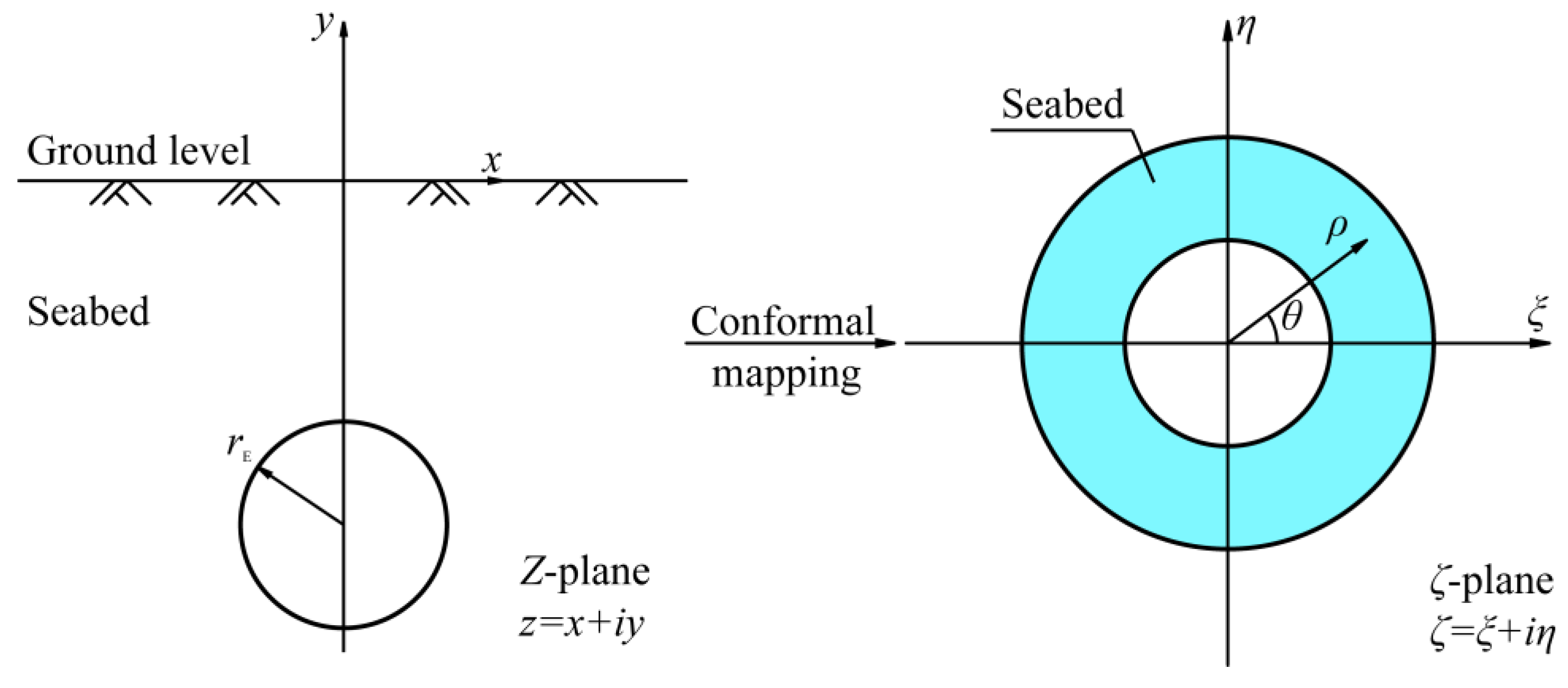
3. Analytical Solution

3.1. Seepage in the Seabed

First, for the seepage in the seabed, the flow function and the hydraulic head function of radial seepage into a single-hole tunnel in an infinite plane were solved. Then, the superposition principle was employed to calculate the hydraulic head of any point M in the seabed when the two tunnels interfere with each other. Finally, the uncertain constants were determined according to the BCs, and the final solution was acquired. The theoretical model of the seepage in the seabed is shown in Figure 2. The parameters r 1 and r 2 are the distances from the centres of Tunnel 1 and Tunnel 2 to any point in the seabed, respectively.
r 1 = x 2 + ( y + H ) 2
r 2 = ( x 2 b ) 2 + ( y + H ) 2
For the symmetrical subsea tunnels, the equal water inflow into both tunnels is denoted by Q. For the polar coordinate system, Equation (1) for seepage in the seabed is converted to the following equation:
d 2 h d r 2 + 1 r d h d r = 0
where r is the seepage radius.
The expression for the water inflow is derived from Darcy’s law as:
Q = 2 π r k S d h d r
where k S is the permeability coefficient of the seabed.
The function of the hydraulic head is acquired by integrating Equation (11):
h = Q 2 π k S ln r + C
where C is the integration constant that can be determined using the BCs.
For the symmetrical tunnels buried deeply in an aquifer, the hydraulic head of an arbitrary point M (x, y) is given according to the superposition principle:
h M = Q 2 π k S ln r 1 + Q 2 π k S ln r 2 + C 0 = Q 2 π k S ln r 1 r 2 + C 0
where C 0 is the integration constant that can be determined using the BCs.
When point M is on the ground surface, the formulations of r 1 and r 2 can be written as follows:
r 1 = x 2 + H 2
r 2 = ( x 2 b ) 2 + H 2
Based on Equations (14) and (15), the following equation can be obtained:
r 2 = r 1 2 + 4 b 2 4 b x
The following equation can then be determined from Equations (13) and (16) and BC1 as:
H w + H = Q 2 π k S ln r 1 r 1 2 + 4 b 2 4 b x + C 0
Conformal mapping, which is illustrated in Figure 3, is applied in this study to obtain r 1 . The seabed in plane Z is represented as an annular field in plane ζ using the following function:
ζ = ξ + i η = z + i a z i a
where z is a point in plane Z, ζ , with coordinates ξ and η , is the mapped point in plane ζ , i is an imaginary unit, and a is a constant that describes the size of the tunnel with an EDZ and is defined as follows:
a = H 2 r E 2
The distance ρ 1 , which is mapped by the distance r 1 in the plane ζ , can be written as:
ρ 1 = | d ζ d z | z = i a r 1 = | 2 i a ( 2 i a ) 2 | r 1 = 1 2 a r 1 = 1
According to Equation (20), r 1 can be obtained as:
r 1 = 2 a
Due to x ( , + ) and H > > r E , x is equal to the average value of the domain of definition (x = 0). Hence, Equation (17) is rewritten by substituting Equation (21) into Equation (17):
H w + H = Q 2 π k S ln ( 4 a a 2 + b 2 ) + C 0
C 0 = H w + H Q 2 π k S ln ( 4 a a 2 + b 2 )
The hydraulic head of an arbitrary point on the circumference of Tunnel 2 can be expressed from Equation (13) and BC3 as follows:
h E = Q 2 π k S ln ( r E r E 2 + 4 b x 4 b 2 ) + C 0
Because x [ 2 b r E , 2 b + r E ] and r E is sufficiently small for 2b, x is equal to the average value of the domain of definition (x = 2b). Then, Equation (24) can be rewritten as:
h E = Q 2 π k S ln ( r E r E 2 + 4 b 2 ) + C 0
Based on Equations (23) and (25), the water inflow into the EDZ is obtained:
Q I = 2 π k S H w + H h E ln 4 ( H 2 r E 2 ) ( H 2 r E 2 + b 2 ) r E r E 2 + 4 b 2

3.2. Seepage in Excavation Damage Zones

The hydraulic head distribution still obeys Equation (10) for EDZs, and the water inflow into the tunnel is given below:
Q II = 2 π r k E d h d r
By performing definite integration on Equation (27) according to BC2 and BC4, Equation (27) is rewritten as follows:
Q II = 2 π k E h E h 0 ln r E r 0
where k E is the permeability coefficient of the EDZs.

3.3. Final Analytical Solution
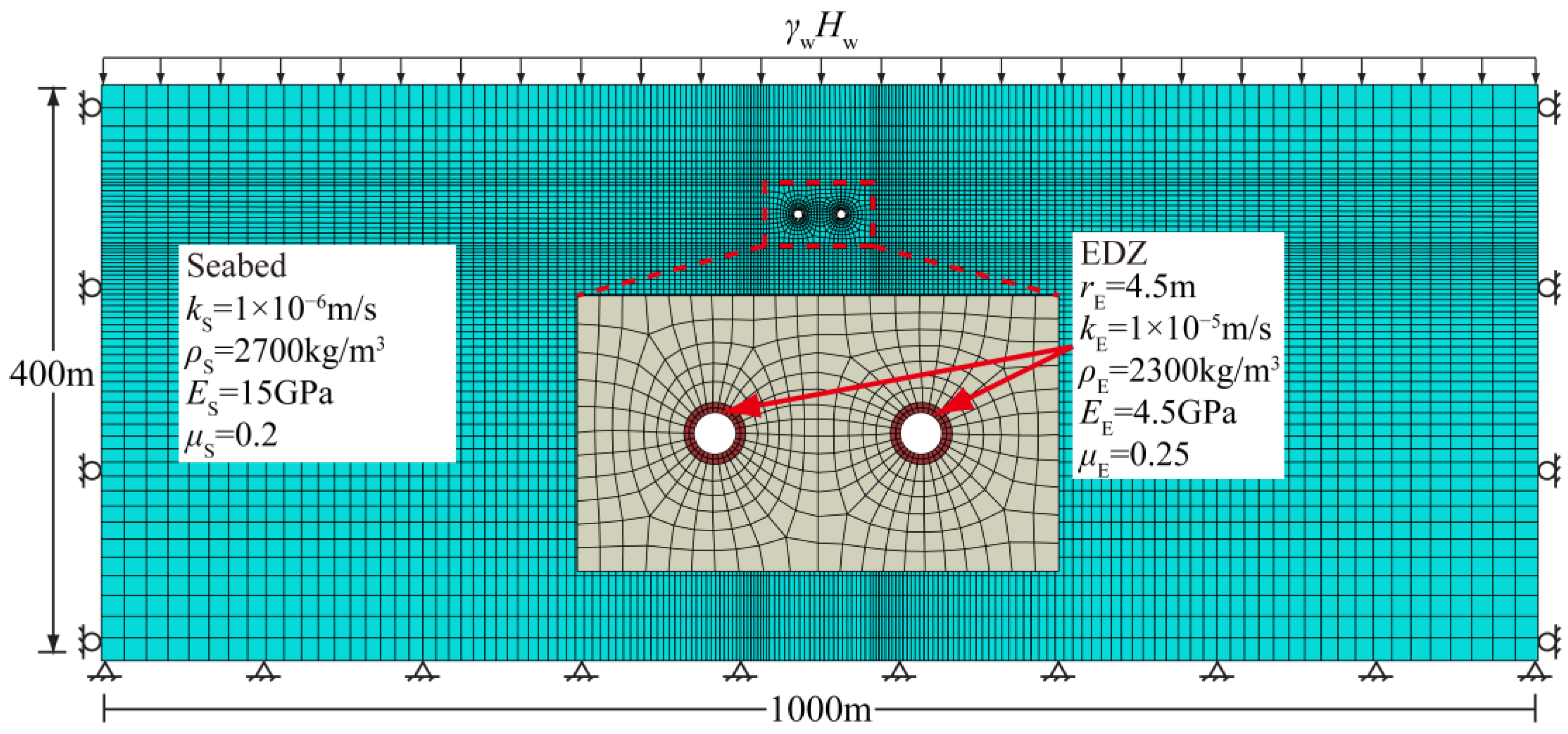
In accordance with the continuity condition, the water inflow into the EDZ is equal to the water inflow into the tunnel, namely,
Q I = Q II
The water inflow into the deeply buried symmetrical subsea tunnels with EDZs ( Q E ) is acquired by substituting Equations (26) and (28) into Equation (29):
Q E = 2 π k S H w + H h 0 A + B
A = ln 4 ( H 2 r E 2 ) ( H 2 r E 2 + b 2 ) r E r E 2 + 4 b 2
B = k S k E ln r E r 0

4. Verification

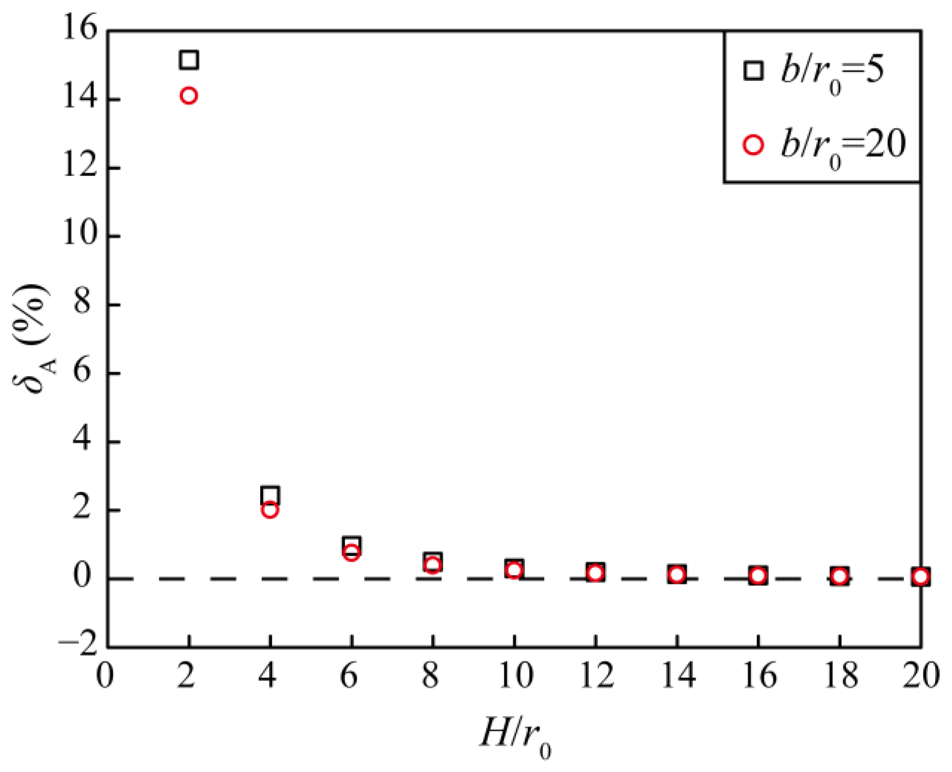
4.1. Comparison with a Simplified Analytical Solution

Wang [15] developed a solution for the water inflow into the symmetrical subsea tunnels without EDZs ( Q W ) as follows:
Q W = 2 π k S H w + H h 0 ln ( 4 H 2 + r 0 2 ) ( 4 H 2 + 4 b 2 + r 0 2 ) r 0 r 0 2 + 4 b 2
If the EDZs are not accounted for, then the proposed analytical solution degenerates to the following form:
Q 0 = 2 π k S H w + H h 0 ln 4 ( H 2 r 0 2 ) ( H 2 r 0 2 + b 2 ) r 0 r 0 2 + 4 b 2
The discrepancy between Q W and Q 0 is compared by a series of calculations, the parameters of which are given in Table 1. The relative error between the above two analytical solutions can be calculated as follows:
δ A = Q 0 Q W Q W × 100 %
Figure 4 shows the relative errors between the above two analytical solutions. In Figure 4, δ A varies from 0.06% to 15.14% when b / r 0 = 5 and varies from 0.06% to 14.10% when b / r 0 = 20 . The relative error is at a maximum when H / r 0 = 2 and gradually tends to zero as H / r 0 increases. The relative error is less than 2.5% when H / r 0 = 4 , and the difference in δ A for b / r 0 = 5 and b / r 0 = 20 gradually tends to zero as H / r 0 increases. The above results indicate that the difference between the two analytical solutions is more pronounced for shallowly buried tunnels ( H / r 0 = 2 ), while there is almost no difference for deeply buried tunnels. In addition, the effect of the distance between the two tunnel centres is small, and the effect disappears with increasing buried depth.

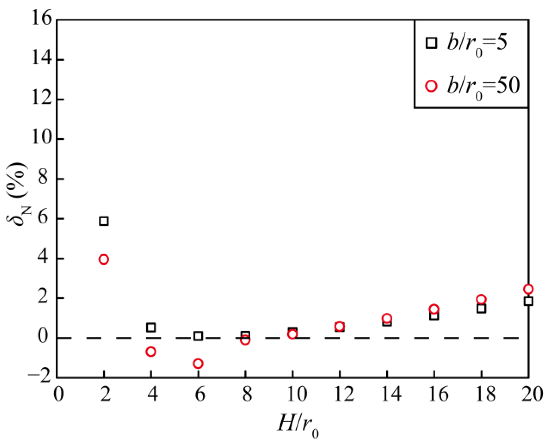
4.2. Comparison with the Numerical Solution

The finite element method (FEM) was utilized to calculate the water inflow under varying circumstances, and then comparisons were made with the results acquired by the proposed solution to examine its dependability. In this study, the commercial software package ABAQUS 2022 was employed for modelling and calculations. Figure 5 illustrates the numerical model and Table 2 presents the dimensional and material parameters. Additional information on the numerical model is given below:
The numerical model is 1000 m wide and 400 m high. In this numerical model, the symmetrical subsea tunnels with EDZs are deeply buried in a seabed and the sea level is horizontal and stable. Both tunnels are 6 m in diameter, and the distance from the ground level to the tunnel centre is H m. The effects of the boundaries can be neglected because the distances from the tunnel centres to the sides and bottom of the model are more than 50 times the diameter. The materials of the numerical model consist of the seabed and the EDZs, which are Mohr–Coulomb constitutive models.
The horizontal displacements on both lateral sides and the displacements at the bottom are constrained in this model. The hydraulic head on both sides is constant, and the underside is impermeable. A zero hydraulic head along the internal perimeter of the tunnels is applied to both the numerical and analytical calculations. A uniform force is assumed to represent the water pressure at the ground level. The relative error between Q E and Q N is calculated as follows:
δ N = Q E Q N Q N × 100 %
Figure 6 depicts the relative errors between Q E and Q N for different values of H / r 0 . In Figure 6, δ N varies from 0.10% to 5.88% when b / r 0 = 5 and varies from −1.29% to 3.95% when b / r 0 = 20 . The relative error is greatest when H / r 0 = 2 and tends to decrease and then increase as H / r 0 increases. The relative error varies from −2% to 2.5% when H / r 0 is greater than or equal to 4. The difference in δ N for b / r 0 = 5 and b / r 0 = 20 is small and decreases and then increases with increasing H / r 0 . The proposed and numerical solutions are in good agreement with each other, and the relative error is slightly larger for smaller H / r 0 but still less than 6% ( b / r 0 = 5 ). Moreover, the change in the distance between the two tunnel centres has a small effect on the relative error.

5. Discussion

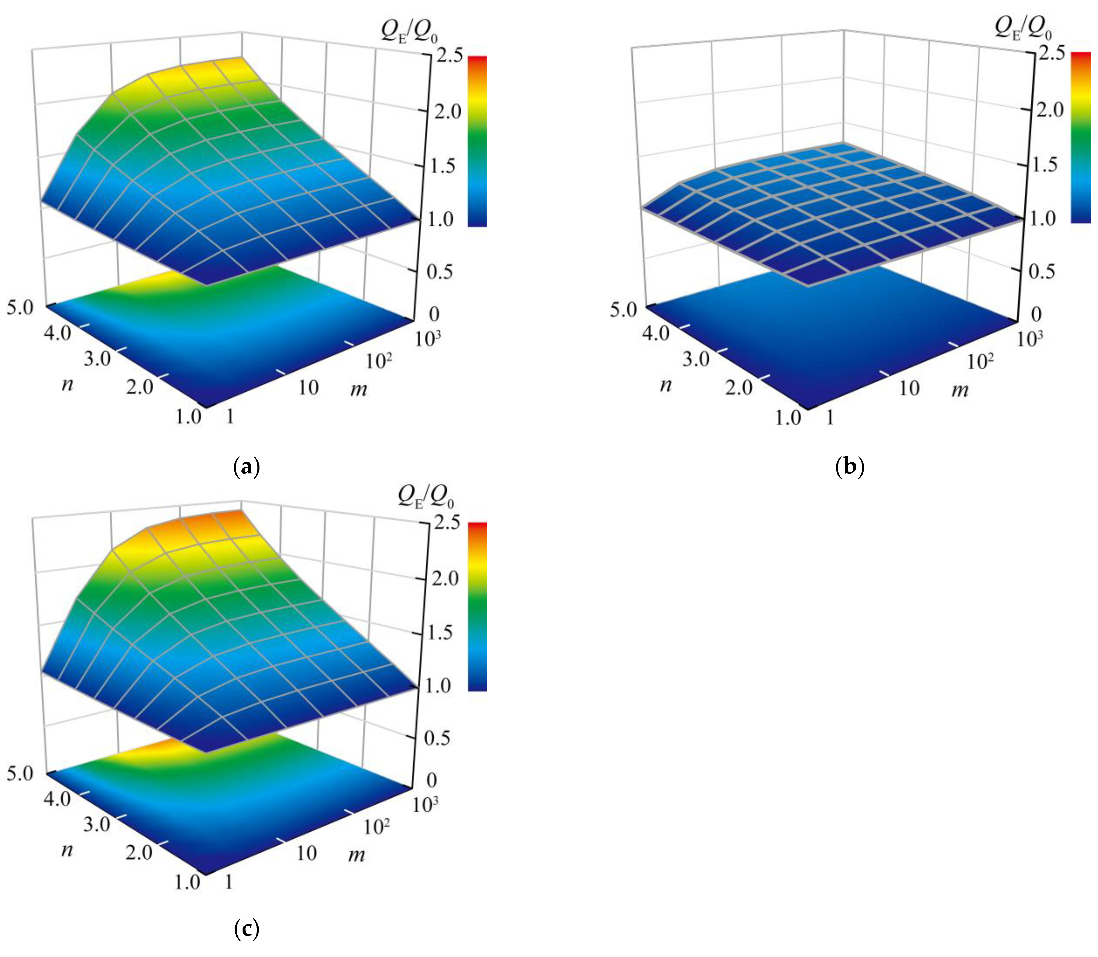
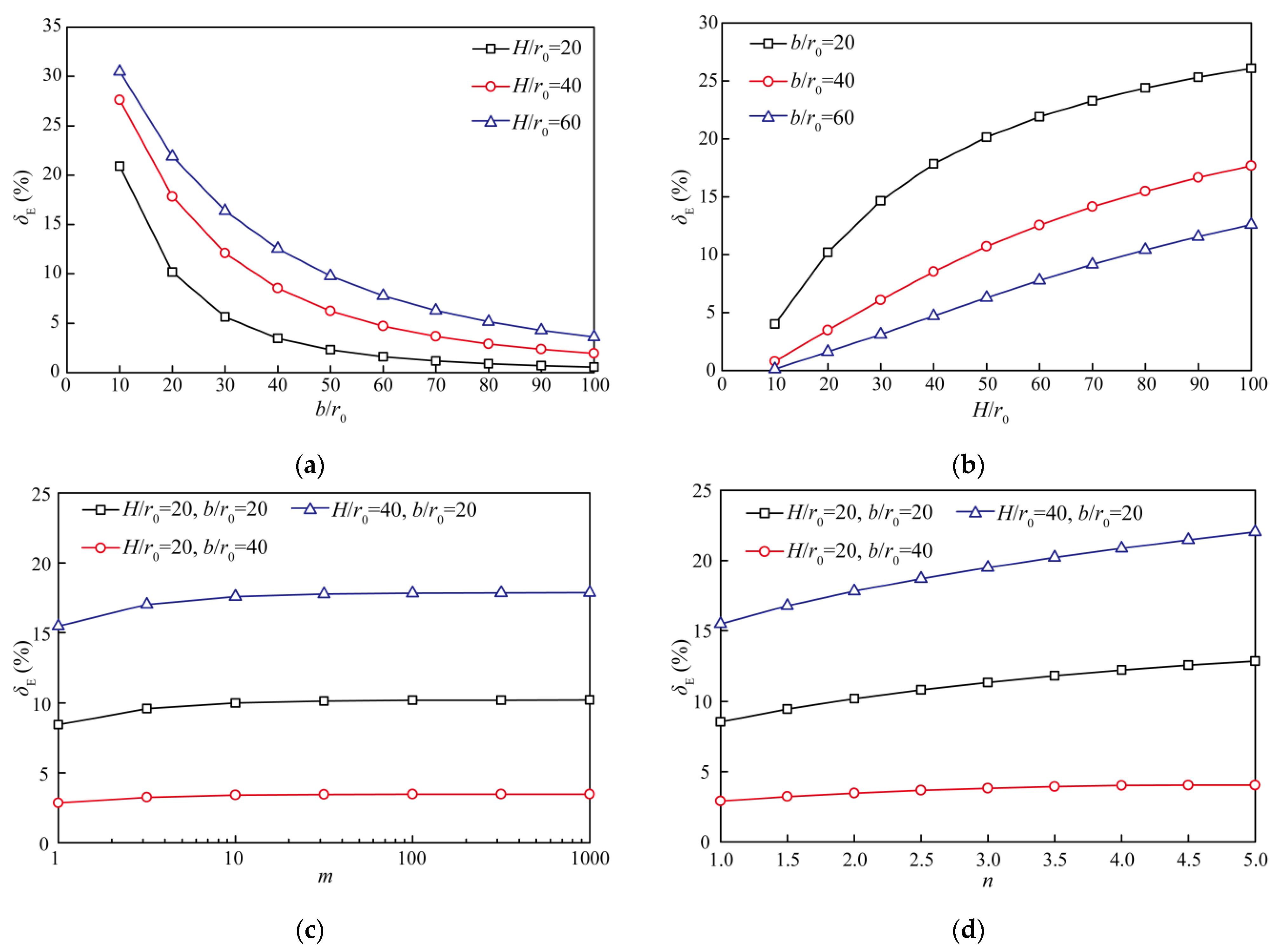
5.1. Effects of Excavation Damage Zones

To further discuss the effects of EDZs on the water inflow, the ratio of the water inflow into tunnels with and without EDZs was calculated and analysed as a function of various EDZ thicknesses and permeability coefficients. The ratio of Equation (30) to Equation (34) is described as follows:
Q E Q 0 = D A + B
D = ln 4 ( H 2 r 0 2 ) ( H 2 r 0 2 + b 2 ) r 0 r 0 2 + 4 b 2
By denoting m = k E / k S and n = r E / r 0 , the EDZ permeability coefficient and thickness are reflected in m and n, respectively, if k S and r 0 are constant. Table 3 shows the parameters for computational analyses regarding the effects of EDZs, and Figure 7 illustrates the variations in Q E / Q 0 under different values of m and n.
In this section, k S and r 0 are kept constant, while the parameter m varies from 1 to 1000 and the parameter n varies from 1 to 5. As shown in Figure 7, Q E / Q 0 reaches a minimum value of 1 when either m or n is equal to 1. Furthermore, Q E / Q 0 increases with increasing parameters m and n, which implies that more water inflow will come with increasing permeability coefficient and thickness of EDZs.
For Figure 7a,c, it should be noted that Q E / Q 0 increases sharply with m when m 10 , whereas Q E / Q 0 increases only very little with increasing m when m exceeds 100. This indicates that there is a relatively significant increase in the water inflow at an early stage of increasing k E , but this effect gradually vanishes as the permeability coefficient further increases.
In addition, Q E / Q 0 increases approximately linearly with n, and the slope increases with m. According to Figure 7c, when m = 1000, the Q E / Q 0 values for n = 2.5 and n = 5 are 1.46 and 2.40, respectively. The thickness of the EDZs has a great impact on the water inflow. Notably, the Q E / Q 0 value in Figure 7b ranges from 1 to 1.27, which is significantly smaller than that in Figure 7a,c. This result suggests that the EDZs have a greater impact on the water inflow into shallower tunnels.

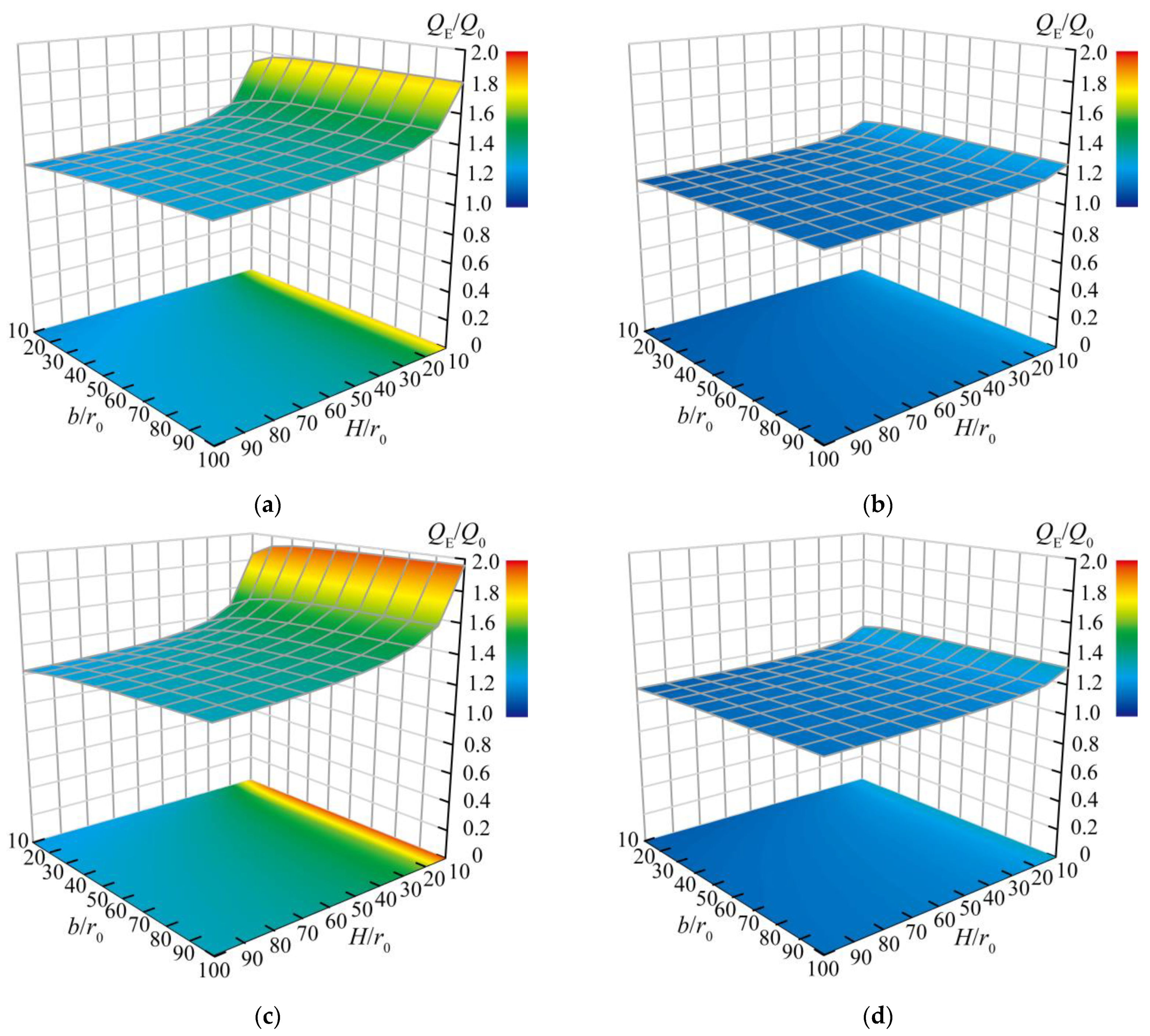
5.2. Effects of Spatial Parameters

In addition to the EDZ parameters, spatial parameters also have an effect on the water inflow. Therefore, a range of computations were performed on the effect of spatial parameters, and the input parameters are detailed in Table 4. The variation in Q E / Q 0 with parameters H / r 0 and b / r 0 is shown in Figure 8.
In Figure 8, Q E / Q 0 decreases as H / r 0 increases, and the magnitude of the decrease also decreases as H / r 0 increases. Taking b / r 0 = 100 in Figure 8c as an example, Q E / Q 0 decreases from 1.96 to 1.61 as H / r 0 increases from 10 to 20 and decreases from 1.34 to 1.33 as H / r 0 increases from 90 to 100. Moreover, Q E / Q 0 increases as b / r 0 increases, but the magnitude of increase decreases as b / r 0 increases. The range of variation in Q E / Q 0 with b / r 0 is obviously smaller than that with H / r 0 . In terms of H / r 0 = 10 in Figure 8c, Q E / Q 0 ranges from 1.84 to 1.96. The above results suggest that the effects of the EDZs are more significant with a smaller buried depth and a greater distance between the two tunnel centres and that the influence of buried depth is stronger.
It is notable that the scopes of variation in Q E / Q 0 when n = 4 in Figure 8a,c are apparently larger than those of n = 2 in Figure 8b,d. In addition, a comparison in Figure 8a,c shows that the Q E / Q 0 value grows with increasing m. The results are consistent with the findings of the previous section. Therefore, we need to consider both the EDZ parameters and the spatial parameters to accurately assess the influence of EDZs.

5.3. Comparison with Analytical Solution for Water Inflow into a Tunnel with an EDZ

Due to the interaction of the symmetrical subsea tunnels, it is meaningful to determine the differences between the analytical solutions for the water inflow into a single subsea tunnel with an EDZ and the water inflow into the symmetrical subsea tunnels with EDZs. Therefore, a range of investigations were performed to examine the differences among the analytical solutions for different spatial parameters ( b / r 0 and H / r 0 ) and EDZ parameters (m and n).
The analytical solution for the water inflow into a single tunnel with an EDZ proposed by Pan [8] is as follows:
Q P = 2 π k S H w + H h 0 ln H + H 2 r E 2 r E + k S k E ln r E r 0
The variance between Q P and Q E can be calculated as follows:
δ E = Q P Q E Q P × 100 %
The parameters for the computational analyses used for a comparison with Pan’s analytical solution are given in Table 5. The variations in δ E with the spatial parameters ( b / r 0 and H / r 0 ) and the EDZ parameters (m and n) are presented in Figure 9. As shown in Figure 9a, δ E decreases and tends to zero with increasing b / r 0 , and the decreasing rate gradually slows. However, δ E increases as H / r 0 increases, and the growth rate gradually slows according to Figure 9b.
The computational results of the proposed solution are always less than those obtained with Pan’s solution, and the differences gradually disappear as the distance between the two tunnel centres increases and the buried depth decreases. The results indicate that there is a diverting effect between the symmetrical subsea tunnels, and this effect will decrease with increasing b / r 0 and decreasing H / r 0 .
Figure 9c,d shows that δ E increases as the EDZ parameters (m and n) increase and the growth rate of δ E slows. For H / r 0 = 20 and b / r 0 = 40 , δ E varies from 2.84% to 3.47% when m increases from 1 to 1000 and varies from 2.91% to 4.03% when n increases from 1 to 5. For H / r 0 = 40 and b / r 0 = 20 , δ E varies from 15.47% to 17.86% when m increases from 1 to 1000 and varies from 15.50% to 22.03% when n increases from 1 to 5.
The above results imply that the EDZs can promote the diverting effect between the two tunnels, and this promotion increases as the buried depth increases and the distance between the two tunnel centres decreases. Moreover, the diverting effect is more sensitive to the EDZ thickness than to the EDZ permeability coefficient.

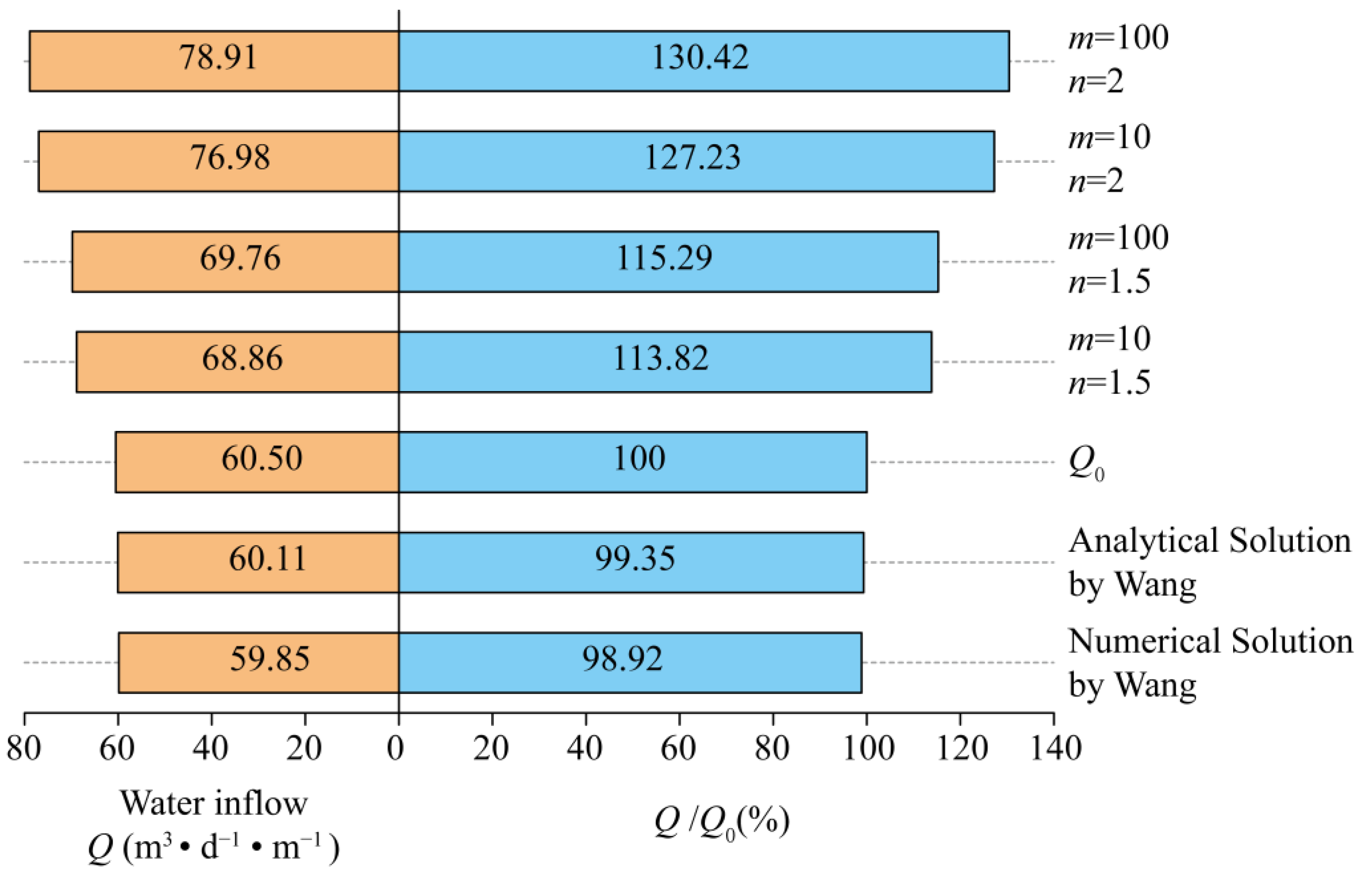
5.4. Application in an Engineering Case

The proposed solution offers a quantitative evaluation method for the water inflow into the deeply buried symmetrical subsea tunnels with EDZs. According to the investigations in Section 5.1, ignoring the effects of EDZs would underestimate the water inflow. To demonstrate that it is necessary to consider the EDZs, the water inflow into the Xiamen Xiang’an tunnel in China was computed using the proposed solution. The data posted in Table 6 for the Xiamen Xiang’an tunnel are found in Wang et al. [15]. The parameters m and n were set to 10 and 100 and 1.5 and 2, respectively.
The computational outcomes of the proposed solution were compared with those obtained by Wang, ignoring the effect of EDZs, as shown in Figure 10. Notably, the calculations in the literature [15] were performed with the assumption of zero water pressure around the tunnel periphery, but zero hydraulic head around the tunnel periphery was applied in this study.
Figure 10 suggests that the result acquired by the proposed solution without EDZs is similar to that obtained by Wang’s solutions, which confirms that the proposed analytical solution has good accuracy. Furthermore, there is a notable growth in the water inflow into the Xiang’an subsea tunnel after considering the EDZs, as shown in Figure 10, where Q / Q 0 varies from 113.82% to 130.42%. The above computational analyses affirm that it is necessary for the assessment of the water inflow into the symmetrical subsea tunnels to account for the effects of EDZs.

6. Conclusions

This research presents an analytical solution for predicting the water inflow into the deeply buried symmetrical subsea tunnels with EDZs by adopting seepage mechanics, conformal mappings, and the superposition principle. The key conclusions are listed below:
(1)
The water inflow into the deeply buried symmetrical subsea tunnels with EDZs is related to parameters that include the permeability coefficients of the seabed and the EDZs ( k S , k E ), the radii of the tunnels and the tunnels with EDZs ( r 0 , r E ), the distance from the sea level to the ground level ( H w ), the distance from the ground level to the tunnel centre ( H ), the distance between the two tunnel centres (2b), and the hydraulic head on the circumference of the tunnels ( h 0 ).
(2)
If the effects of the EDZs are neglected, the relative error between the proposed solution and an analytical solution for the water inflow into the symmetrical subsea tunnels without EDZs developed by Wang is always less than 2.5% when H / r 0 4 . If the effects of the EDZs are accounted for, the relative error between the proposed solution and the numerical solution is still always less than 2.5% when H / r 0 4 . The comparisons prove that the proposed solution is applicable to the evaluation of the water inflow into the deeply buried symmetrical subsea tunnels.
(3)
The effects of EDZs on the water inflow into the deeply buried symmetrical subsea tunnels were analysed based on the EDZ parameters m ( k E / k S ) and n ( r E / r 0 ). Firstly, Q E / Q 0 increases significantly at an early stage of increasing m and then gradually stabilizes as m increases further. Moreover, Q E / Q 0 increases approximately linearly with n, which implies that the thickness of EDZs has a strong effect on the water inflow.
(4)
For spatial parameters, Q E / Q 0 decreases as H / r 0 increases but increases as b / r 0 increases. The effects of the EDZs are more significant with smaller buried depths and greater distances between the two tunnel centres and this effect gradually stabilizes as buried depth and distance between the two tunnel centres increase. Changes in H affect the effects of EDZs more than changes in 2b.
(5)
Compared with a single subsea tunnel, there is a diverting effect between the symmetrical subsea tunnels. This diverting effect can be promoted by increasing the EDZ parameters and is more sensitive to the EDZ thickness than to the EDZ permeability coefficient. In addition, this diverting effect increases as the buried depth increases and the distance between the two tunnel centres decreases.
(6)
The application in the engineering case shows that the proposed solution has good reliability and that the effects of EDZs should be accounted for when assessing the water inflow into the deeply buried symmetrical subsea tunnels with EDZs. In this paper, for m = 100 and n = 2, the water inflow into tunnels considering EDZs is 30.42% higher than that without considering EDZs’ effects. Further efforts can be made to conduct relevant research on prevention methods to diminish the effects of EDZs and on analytical solutions for the water inflow into asymmetrical subsea tunnels with EDZs.

Author Contributions

Conceptualization, Y.P. (Yiheng Pan), J.Q. and P.X.; Methodology, Y.P. (Yiheng Pan), J.Z. and Y.P. (Yaxiong Peng); Validation, P.X. and Y.P. (Yaxiong Peng); Writing—original draft preparation, Y.P. (Yiheng Pan), J.Q. and P.X.; Writing—review and editing, J.Q., J.Z. and Y.P. (Yaxiong Peng); Funding acquisition, Y.P. (Yiheng Pan) and J.Z. All authors have read and agreed to the published version of the manuscript.

Funding

This work was funded by the National Key Research and Development Program of China, grant number 2021YFB2601100, and the Natural Science Foundation of Fujian, grant number 2020J05145.

Data Availability Statement

Data is available on request from the corresponding author.

Conflicts of Interest

The authors declare no conflict of interest.

References

  1. Nilsen, B. Characteristics of Water Ingress in Norwegian Subsea Tunnels. Rock Mech. Rock Eng. 2014, 47, 933–945. [Google Scholar] [CrossRef]
  2. Zhu, C.; Ying, H.; Gong, X.; Wang, X.; Wu, W. Analytical solution for wave-induced hydraulic response on subsea shield tunnel. Ocean Eng. 2021, 228, 108924. [Google Scholar] [CrossRef]
  3. Liu, X.; Wang, D.; Zhang, Y.; Jiang, A.; Fang, Q.; Zhang, R. Analytical solutions on non-Darcy seepage of grouted and lined subsea tunnels under dynamic water levels. Ocean Eng. 2023, 267, 113276. [Google Scholar] [CrossRef]
  4. Li, P.; Wang, F.; Long, Y.; Zhao, X. Investigation of steady water inflow into a subsea grouted tunnel. Tunn. Undergr. Sp. Technol. 2018, 80, 92–102. [Google Scholar] [CrossRef]
  5. Wang, H.; Chen, J.; Liu, H.; Guo, L.; Lu, Y.; Su, X.; Zhu, Y.; Liu, T. Study on the Influence of Mud Properties on the Stability of Excavated Face of Slurry Shield and the Quality of Filter Cake Formation. J. Mar. Sci. Eng. 2020, 8, 291. [Google Scholar] [CrossRef]
  6. Li, S.; Zhou, Z.; Li, L.; Xu, Z.; Zhang, Q.; Shi, S. Risk assessment of water inrush in karst tunnels based on attribute synthetic evaluation system. Tunn. Undergr. Sp. Technol. 2013, 38, 50–58. [Google Scholar] [CrossRef]
  7. Zhou, J.; Liu, H.; Li, C.; He, X.; Tang, H.; Zhao, X. A semi-empirical model for water inflow into a tunnel in fractured-rock aquifers considering non-Darcian flow. J. Hydrol. 2021, 597, 126149. [Google Scholar] [CrossRef]
  8. Pan, Y.; Qi, J.; Zhang, J.; Peng, Y.; Chen, C.; Ma, H.; Ye, C. A Comparative Study on Steady-State Water Inflow into a Circular Underwater Tunnel with an Excavation Damage Zone. Water 2022, 14, 3154. [Google Scholar] [CrossRef]
  9. Liu, R.; Liu, Y.; Xin, D.; Li, S.; Zheng, Z.; Ma, C.; Zhang, C. Prediction of water inflow in subsea tunnels under blasting vibration. Water 2018, 10, 1336. [Google Scholar] [CrossRef]
  10. Zhao, J.; Tan, Z.; Ma, N. Development and application of a new reduction coefficient of water pressure on sub-sea tunnel lining. Appl. Sci. 2022, 12, 2496. [Google Scholar] [CrossRef]
  11. Zhao, J.; Tan, Z.; Zhou, Z. Discussion on the waterproof and drainage system of the coastal tunnel and analysis of water pressure law outside lining: A case study of the gongbei tunnel. Adv. Civ. Eng. 2021, 2021, 6610601. [Google Scholar] [CrossRef]
  12. Harr, M.E. Groundwater and Seepage. Soil Sci. 1963, 95, 289. [Google Scholar] [CrossRef]
  13. Goodman, R.E.; Moye, D.G.; Schalkwyk, A.; Javandel, I. Ground water inflow during tunnel driving. Eng. Geol. 1965, 2, 39–56. [Google Scholar]
  14. Qin, Z.; He, W.; Zhou, H. Analytical study on seepage field of subsea twin tunnels constructed by NATM. Ocean Eng. 2022, 264, 112345. [Google Scholar] [CrossRef]
  15. Wang, F.; Li, P. An Analytical Model of Seepage Field for Symmetrical Underwater Tunnels. Symmetry 2018, 10, 273. [Google Scholar] [CrossRef]
  16. Zhang, B. Analytical Solution for Seepage Field of Twin-parallel Tunnels in Semi-infinite Plane. J. China Railw. Soc. 2017, 39, 125–131. [Google Scholar]
  17. Guo, Y.; Wang, H.; Jiang, M. Analytical solutions of seepage field for underwater shallow-buried parallel twin tunnels. Chin. J. Geotech. Eng. 2021, 43, 1088–1096. [Google Scholar]
  18. Zhu, C.; Ying, H.; Gong, X.; Shen, H.; Wang, X. Analytical solutions to seepage field of underwater twin parallel tunnels. Chin. J. Geotech. Eng. 2019, 41, 355–360. [Google Scholar]
  19. Pan, Y.; Luo, Q.; Zhou, B.; Chen, J. Analytical study on seepage field of deep tunnel with grouting circle in half plane. J. Zhejiang Univ. Eng. Sci. 2018, 52, 1114–1122. [Google Scholar]
  20. Huangfu, M.; Wang, M.; Tan, Z.; Wang, X. Analytical solutions for steady seepage into an underwater circular tunnel. Tunn. Undergr. Sp. Technol. 2010, 25, 391–396. [Google Scholar] [CrossRef]
  21. Park, K.; Owatsiriwong, A.; Lee, J. Analytical solution for steady-state groundwater inflow into a drained circular tunnel in a semi-infinite aquifer: A revisit. Tunn. Undergr. Sp. Technol. 2008, 23, 206–209. [Google Scholar] [CrossRef]
  22. Kolymbas, D.; Wagner, P. Groundwater ingress to tunnels—The exact analytical solution. Tunn. Undergr. Sp. Technol. 2007, 22, 23–27. [Google Scholar] [CrossRef]
  23. El Tani, M. Circular tunnel in a semi-infinite aquifer. Tunn. Undergr. Sp. Technol. 2003, 18, 49–55. [Google Scholar] [CrossRef]
  24. Huang, Z.; Zhu, S.; Zhao, K.; Li, X.; Wu, R.; Wang, Y.; Wang, X. Influence of Structural Variation of Host Rock Induced by Engineering Activities on Water Inrush of Tunnels. Chin. J. Geotech. Eng. 2018, 40, 449–458. [Google Scholar]
  25. Yang, G.; Wang, X.; Wang, X.; Cao, Y. Analyses of seepage problems in a subsea tunnel considering effects of grouting and lining structure. Mar. Georesour. Geotec. 2016, 34, 65–70. [Google Scholar] [CrossRef]
  26. Wang, X.; Tan, Z.; Wang, M.; Zhang, M.; Ming, H. Theoretical and experimental study of external water pressure on tunnel lining in controlled drainage under high water level. Tunn. Undergr. Sp. Technol. 2008, 23, 552–560. [Google Scholar] [CrossRef]
  27. Hwang, J.; Lu, C. A semi-analytical method for analyzing the tunnel water inflow. Tunn. Undergr. Sp. Technol. 2007, 22, 39–46. [Google Scholar] [CrossRef]
  28. Farhadian, H.; Katibeh, H.; Huggenberger, P. Empirical model for estimating groundwater flow into tunnel in discontinuous rock masses. Environ. Earth Sci. 2016, 75, 471. [Google Scholar] [CrossRef]
  29. Farhadian, H.; Katibeh, H. New empirical model to evaluate groundwater flow into circular tunnel using multiple regression analysis. Int. J. Min Sci. Technol. 2017, 27, 415–421. [Google Scholar] [CrossRef]
  30. Nikvar Hassani, A.; Farhadian, H.; Katibeh, H. A comparative study on evaluation of steady-state groundwater inflow into a circular shallow tunnel. Tunn. Undergr. Sp. Technol. 2018, 73, 15–25. [Google Scholar] [CrossRef]
  31. Nikvar Hassani, A.; Katibeh, H.; Farhadian, H. Numerical analysis of steady-state groundwater inflow into Tabriz line 2 metro tunnel, northwestern Iran, with special consideration of model dimensions. B. Eng. Geol. Environ. 2016, 75, 1617–1627. [Google Scholar] [CrossRef]
  32. Farhadian, H.; Katibeh, H.; Huggenberger, P.; Butscher, C. Optimum model extent for numerical simulation of tunnel inflow in fractured rock. Tunn. Undergr. Sp. Technol. 2016, 60, 21–29. [Google Scholar] [CrossRef]
  33. Zhu, W.C.; Wei, J.; Zhao, J.; Niu, L.L. 2D numerical simulation on excavation damaged zone induced by dynamic stress redistribution. Tunn. Undergr. Sp. Technol. 2014, 43, 315–326. [Google Scholar] [CrossRef]
  34. Siren, T.; Kantia, P.; Rinne, M. Considerations and observations of stress-induced and construction-induced excavation damage zone in crystalline rock. Int. J. Rock Mech. Min. 2015, 73, 165–174. [Google Scholar] [CrossRef]
  35. Martino, J.B.; Chandler, N.A. Excavation-induced damage studies at the Underground Research Laboratory. Int. J. Rock Mech. Min. 2004, 41, 1413–1426. [Google Scholar] [CrossRef]
  36. Bossart, P.; Meier, P.M.; Moeri, A.; Trick, T.; Mayor, J. Geological and hydraulic characterisation of the excavation disturbed zone in the Opalinus Clay of the Mont Terri Rock Laboratory. Eng. Geol. 2002, 66, 19–38. [Google Scholar] [CrossRef]
  37. Souley, M.; Homand, F.; Pepa, S.; Hoxha, D. Damage-induced permeability changes in granite: A case example at the URL in Canada. Int. J. Rock Mech. Min. 2001, 38, 297–310. [Google Scholar] [CrossRef]
Figure 1. Theoretical model of symmetrical subsea tunnels with excavation damage zones in an aquifer with a horizontal water level.
Water 15 03556 g001
Figure 2. Theoretical model of seepage in the seabed.
Water 15 03556 g002
Figure 3. Plane of conformal mapping.
Water 15 03556 g003
Figure 4. Difference between analytical solutions with different H / r 0 values.
Water 15 03556 g004
Figure 5. Numerical model for water inflow into deeply buried symmetrical subsea tunnels with excavation damage zones.
Water 15 03556 g005
Figure 6. Difference between the analytical and numerical solutions with various H / r 0 values.
Water 15 03556 g006
Figure 7. Variation in Q E / Q 0 with parameters m and n: (a) H / r 0 = 10 , b / r 0 = 10 ; (b) H / r 0 = 100 , b / r 0 = 10 ; and (c) H / r 0 = 10 , b / r 0 = 100 .
Water 15 03556 g007
Figure 8. Variation in Q E / Q 0 with H / r 0 and b / r 0 : (a) m = 10, n = 4; (b) m = 10, n = 2; (c) m = 1000, n = 4; and (d) m = 1000, n = 2.
Water 15 03556 g008
Figure 9. Variation in δ E with the spatial parameters ( b / r 0 and H / r 0 ) and the EDZ parameters (m and n): (a) b / r 0 (m = 100, n = 2); (b) H / r 0 (m = 100, n = 2); (c) m; and (d) n.
Water 15 03556 g009
Figure 10. Water inflow into Xiamen Xiang’an Tunnel under various EDZ parameters.
Water 15 03556 g010
Table 1. Parameters for comparison of Q W and Q 0 .
Distance between Two Tunnel Centres
2 b (m)
Permeability Coefficient of Seabed
k S (m/s)
Radii of Tunnels
r 0 (m)
Distance from Sea Level to Ground Level
H w (m)
Hydraulic Head on the Circumference of Tunnels
h 0 (m)
Distance from Ground Level to Tunnel Centre
H (m)
301 × 10−634506–60
120
Table 2. Dimensional and material parameters of the numerical model.
Dimensional ParametersMaterial Parameters
Radii of tunnels r 0 (m)3Permeability coefficient of seabed k S (m/s)1 × 10−6
Distance from sea level to ground level H w (m)45Permeability coefficient of EDZs k E (m/s)1 × 10−5
Distance from ground level to tunnel centre H (m)6–60Density of seabed ρ S (kg/m3)2700
Hydraulic head on the circumference of tunnels h 0 (m)0Density of EDZs ρ E (kg/m3)2300
Distance between two tunnel centres
2 b (m)
30, 300Young’s modulus of seabed
E S (GPa)
15
Radii of tunnels with EDZs
r E (m)
4.5Young’s modulus of EDZs
E E (GPa)
4.5
Seabed thickness (m)400Poisson’s ratio of seabed
μ S (m/s)
0.2
Seabed width (m)1000Poisson’s ratio of EDZs
μ E (m/s)
0.25
Table 3. Parameters for computational analyses on the effects of excavation damage zones.
Permeability Coefficient of Seabed
k S (m/s)
Ratio of EDZ Permeability to Seabed Permeability
m
Radii of Tunnels
r 0 (m)
Ratio of Radii of Tunnels with EDZs to Radii of Tunnels
n
Distance from Sea Level to Ground Level
H w (m)
Distance between Two Tunnel Centres
2 b (m)
Distance from Ground Level to Tunnel Centre
H (m)
Hydraulic Head on the Circumference of Tunnels
h 0 (m)
1 × 10−61–100031–54560, 60030, 3000
Table 4. Parameters for computational analyses on the effects of spatial parameters.
Permeability Coefficient of Seabed
k S (m/s)
Ratio of EDZ Permeability to Seabed Permeability
m
Radii of Tunnels
r 0 (m)
Ratio of Radii of Tunnels with EDZs to Radii of Tunnels
n
Distance from Sea Level to Ground Level
H w (m)
Distance between Two Tunnel Centres
2 b (m)
Distance from Ground Level to Tunnel Centre
H (m)
Hydraulic Head on the Circumference of Tunnels
h 0 (m)
1 × 10−610, 100032, 44560–60030–3000
Table 5. Parameters for computational analyses for a comparison with the analytical solution for water inflow into a tunnel with an EDZ.
Permeability Coefficient of Seabed
k S (m/s)
Ratio of EDZ Permeability to Seabed Permeability
m
Radii of Tunnels
r 0 (m)
Ratio of Radii of Tunnels with EDZs to Radii of Tunnels
n
Distance from Sea Level to Ground Level
H w (m)
Distance between Two Tunnel Centres
2 b (m)
Distance from Ground Level to Tunnel Centre
H (m)
Hydraulic Head on the Circumference of Tunnels
h 0 (m)
1 × 10−61–100031–54560–60030–3000
Table 6. Parameters for application in an engineering case.
Permeability Coefficient of Seabed
k S (m/s)
Ratio of EDZ Permeability to Seabed Permeability
m
Radii of Tunnels
r 0 (m)
Ratio of Radii of Tunnels with EDZs to Radii of Tunnels
n
Distance from Sea Level to Ground Level
H w (m)
Distance between Two Tunnel Centres
2 b (m)
Distance from Ground Level to Tunnel Centre
H (m)
Hydraulic Head on the Circumference of Tunnels
h 0 (m)
5 × 10−6101007.41.522066.852.40
Disclaimer/Publisher’s Note: The statements, opinions and data contained in all publications are solely those of the individual author(s) and contributor(s) and not of MDPI and/or the editor(s). MDPI and/or the editor(s) disclaim responsibility for any injury to people or property resulting from any ideas, methods, instructions or products referred to in the content.

