Abstract
In the past four decades, membrane development has occurred based on the demand in pressure driven processes. However, in the last decade, the interest in osmotically driven processes, such as forward osmosis (FO) and pressure retarded osmosis (PRO), has increased. The preparation of customized membranes is essential for the development of these technologies. Recently, several very promising membrane preparation methods for FO/PRO applications have emerged. Preparation of thin film composite (TFC) membranes with a customized polysulfone (PSf) support, electorspun support, TFC membranes on hydrophilic support and hollow fiber membranes have been reported for FO/PRO applications. These novel methods allow the use of other materials than the traditional asymmetric cellulose acetate (CA) membranes and TFC polyamide/polysulfone membranes. This review provides an outline of the membrane requirements for FO/PRO and the new methods and materials in membrane preparation.
1. Introduction
The phenomenon of osmosis was first investigated in 1748 by the French cleric Abbé Nollet [1,2]. The membranes used in the experiments then were primarily from animals and plants. The first synthetic semi-permeable membrane, a gelatinous film of copper ferrocyanide, was prepared by Traube more than a hundred years later [1,3]. However, the breakthrough in synthetic membrane fabrication took place in 1963 when Loeb and Sourirajan prepared an asymmetric cellulose acetate membrane with superior properties compared to what had been tested at that time [4]. This was a turning point in membrane science and initiated a lot of research. Thus, in the early 1970s, composite polyamide membranes were patented by Cadotte [5,6,7]. Interfacial polymerization (IP) proved to be an excellent method to obtain a very thin active layer on a support membrane [8,9]. Since then, a lot of progress has been made in the field of osmotic membrane fabrication. Figure 1 illustrates the number of publications containing “reverse osmosis” (RO) “pressure retarded osmosis” (PRO) and “forward osmosis” (FO). Before the mid-60s not much research were published on RO, but after the development of the Loeb-Sourirajan membrane there was a drastic increase in the number of publications. The increased scientific interest in RO continued with the development of the composite membranes, and from 1990, an almost exponential increase in publications is observed.
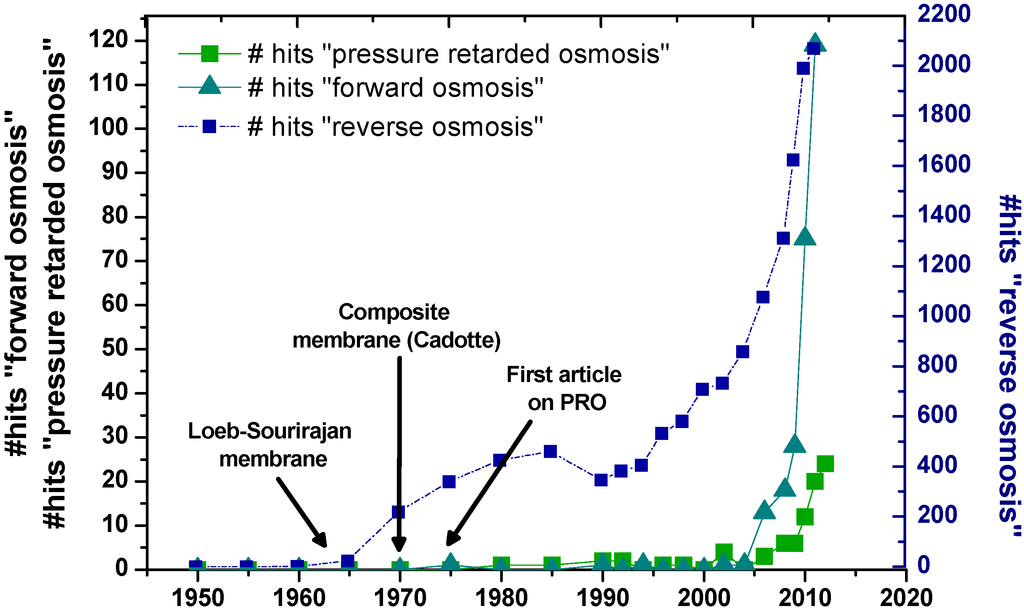
Figure 1.
The number (#) of publications on pressure retarded osmosis, forward osmosis and reverse osmosis from 1950 until 2012 [10].
In 1976, Sidney Loeb proposed pressure retarded osmosis (PRO) as a novel application for osmotic membranes [11,12]. The oil prices at that time were low and therefore the interest in further development of this technology was low. However, in the 1980’s the researchers Dr. Thor Thorsen and Dr. Torleif Holt at SINTEF (Norway) started to investigate the theoretical potential of PRO. In 1997, they started a project together with the Norwegian company Statkraft [13,14]. Statkraft identified the commercial potential and opened the world’s first PRO pilot plant in 2009. PRO utilizes the osmotic pressure difference between two source waters of different salinity to perform work and thus produce energy. Osmotic pressure provided by saline water draws fresh water through a semi-permeable membrane. The diluted draw solution, with a greater volume and/or pressure, moves through a turbine to produce electricity. An illustration of a PRO plant is presented in Figure 2A.
FO as a method to desalinate water has been investigated for almost four decades, stimulating great advances in FO membrane preparation and theory. With the right draw solution, the technology can desalinate water by the use of waste heat or low-grade heat. Batchelder patented in 1965 a method of FO-desalination suggesting a draw solution with sulfur dioxide [15]. Following this, several methods and designs were reported and patented [16,17,18,19,20,21]. Different draw solutions were suggested: precipitable salts, sugar, gas, solvents potassium nitrate and even magnetic nanoparticles [22]. A potentially suitable draw solution is ammonium bicarbonate, a salt that decomposes into ammonia (NH3) and carbon dioxide (CO2) upon moderate heating [23]. Other FO applications are: concentration of digested biomass, direct potable reuse for advanced life support systems, hydration bags, food processing and osmotic pumps for drug delivery in the pharmaceutical industry [24,25,26,27,28,29].
A review on the future of RO and FO seawater desalination was published in 2011 by Elimelech and Phillip [30]. Several other reviews on PRO and FO have been published in the last decade [24,31,32,33,34,35,36,37,38]. However, few of them deal with membrane materials and methods in detail. Recently, several very promising membrane preparation methods for FO/PRO applications have emerged. These novel methods might also allow the use of other materials than the traditional cellulose acetate (CA) and thin film composite (TFC) polyamide/polysulfone. This review provides an outline for these new methods and materials.
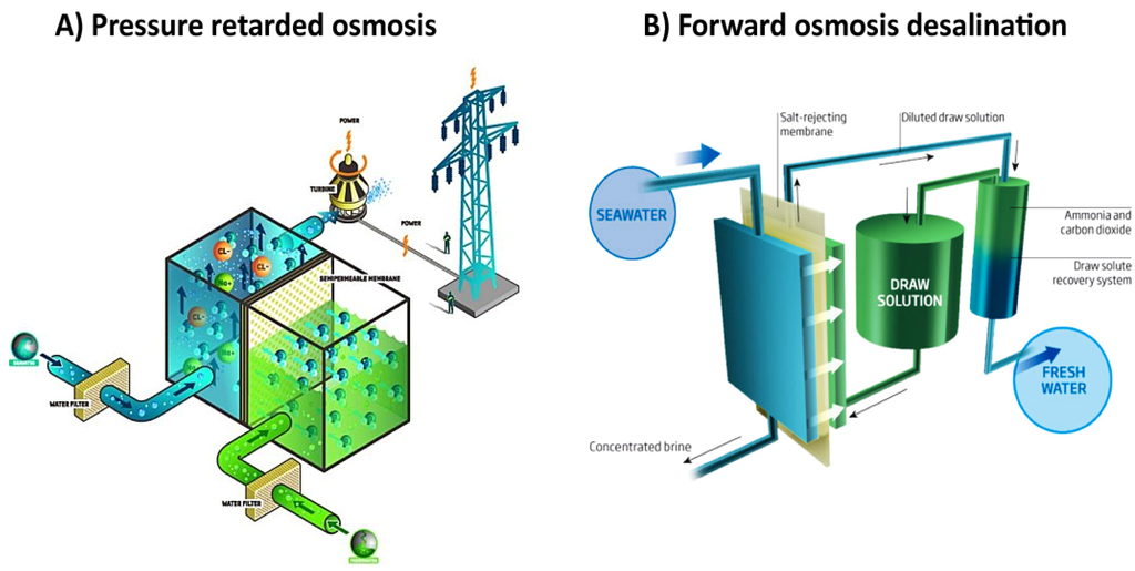
Figure 2.
(A) An illustration of a PRO power plant [13]; (B) An illustration of forward osmosis desalination [39].
1.1. Osmotically Driven Membrane Processes
Osmosis is spontaneous transport of solvent molecules from a dilute solution to a more concentrated solution across a semipermeable membrane. In RO, ΔP > Δπ and in FO, ΔP = 0. PRO is defined as the region between osmosis and osmotic equilibrium, where ΔP < Δπ. Figure 3 illustrates the different classifications of osmotic processes. An ideal semipermeable membrane allows passage of the solvent molecules but not the passage of solutes. The osmotic pressure (π) is defined as a function of the number of solute molecules (n), the volume of the pure solvent (Vm) and the temperature (T). R is the ideal gas constant and i the dimensionless Van’t Hoff factor:


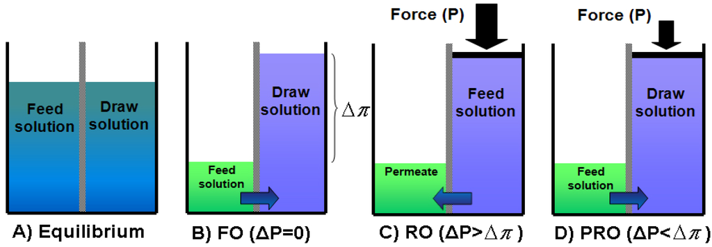
Figure 3.
The different classifications of osmotic pressures: (A) osmotic equilibrium; (B) FO (ΔP =0); (C) RO (ΔP > Δπ) and (D) PRO (ΔP < Δπ). Illustration adapted from [24].
The driving force is the difference in chemical potential of solvent A across the membrane (∆μ). At equilibrium the chemical potential of the pure solvent (  ) is equal to the chemical potential of the solvent in solution (μA) [40]:
 xA is the mole fraction of the solvent, P is the pressure and π is the osmotic pressure.
 ) is equal to the chemical potential of the solvent in solution (μA) [40]:

1.2. The A, B and S Parameters
The water permeability coefficient (A), the solute permeability coefficient (B) and the structure parameter (S) describe the inherent properties of an osmotic membrane (Figure 4). An osmotically driven membrane process should achieve high water flux and minimize the reverse solute flux (high A and low B) [41]. Furthermore, the S parameter should be minimized to reduce internal concentration polarization (ICP, Section 1.3) [42]. The general equation of water transport in an osmotically driven process is:
 where JW is the water flux and A is the water permeability coefficient of the membrane.

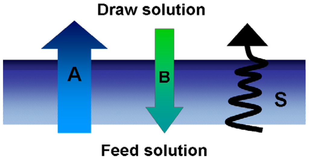
Figure 4.
Illustration of the A, B and S parameters of an osmotic membrane (in PRO mode). A describes the water permeation, B describes the solute permeation and S describes the pathway of the water through the membrane.
The solute permeability coefficient B, is described by [40,43]:
 where k is the mass transfer coefficient for a given membrane cell. The structure parameter (S) describes the support layer [44]:
 where x is the thickness of the support layer, τ is the tortuosity and φ is the porosity. The desired value for the structure parameter in a PRO membrane is lower than 1500 μm [44]. Standard RO membranes have a structure parameter ~10,000 μm [44]. Table 1 presents the structure parameters of some FO/PRO membranes and one commercial RO membrane.


Table 1.
The S-values reported in literature for some FO/PRO membranes and one commercial RO membrane.
| Membrane Characteristics | S (μm) | Reference | ||
|---|---|---|---|---|
| FS * | Commercial FO membrane (CA) HTI | 481 | [41] | |
| 575 | [45] | |||
| FS * | TFC polysulfone-polyamide | 431 | [46] | |
| FS * | 670 | [47] | ||
| HF ** | TFC polyethersulfone-polyamide | 219 | [48] | |
| HF ** | 595 | [49] | ||
| FS * | Commercial RO membrane, DowFilmTec BW30 | With backing fabric | 37 500 | [47] |
| Without backing fabric | 14 000 | |||
* Flat sheet membrane; ** Hollow fiber membrane.
1.3. Internal Concentration Polarization
Internal concentration polarization (ICP) is closely related to external concentration polarization (ECP) at the surface of the active layer. ECP occurs in both pressure driven processes and in osmotically driven membrane processes. However, ICP occurs exclusively in osmotically driven membrane processes (FO and PRO). The concentration polarization occurs within the porous support layer and cannot be reduced by altering the shear rate and/or turbulence of flow across the membrane. The nature of ICP depends on membrane orientation. When the active layer is facing the draw solution the orientation is generally called PRO mode, when the support layer is facing the draw solution it is called FO mode (Figure 5). Concentrative ICP occurs when the active layer of the membrane is facing the draw solution. Draw solute accumulated at the interface between the active layer and the support layer reduces the effective driving force. Dilutive ICP occurs when the active layer of the membrane is facing the feed solution. The water flux from the feed solution dilutes the draw solution in the porous support, resulting in a decrease in the transmembrane osmotic pressure. ICP in both PRO mode and FO mode is illustrated in Figure 5. Dilutive ICP will be more severe with larger molecular weight solutes that cannot diffuse as quickly through the porous support. Furthermore, concentration polarization was found to be more severe in FO mode [50,51].
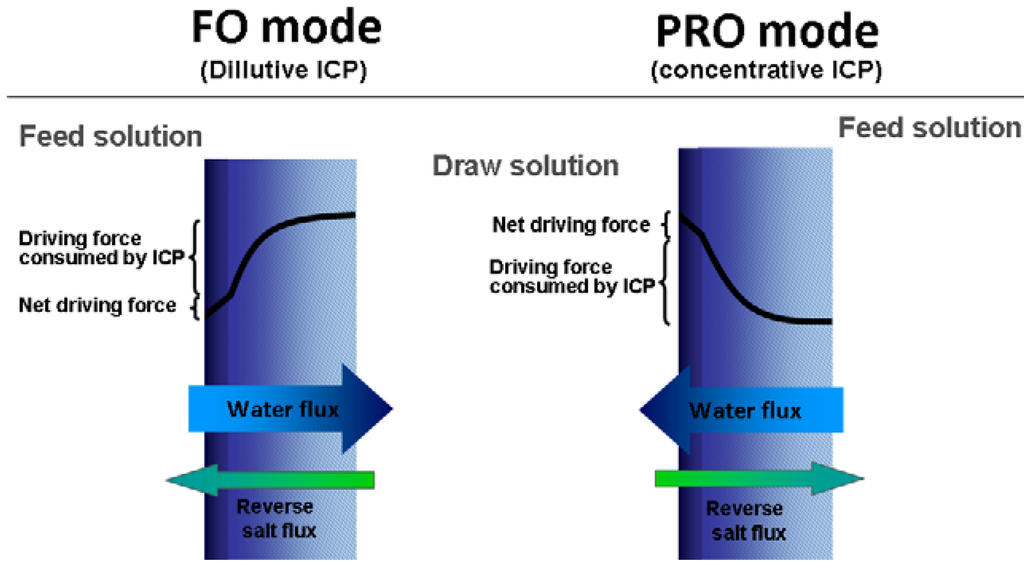
Figure 5.
Illustration of dilutive and concentrative internal concentration polarization (ICP). Figure adapted from [50].
1.4. Reverse Draw Solute Permeation
Reverse permeation of solutes from the draw solution into the feed solution decreases the osmotic driving force. Consequently this reduces the membrane efficiency in both PRO and FO [52]. In a FO system, this could dramatically increase the costs of the process. Phillip et al. developed a model describing the reverse draw solute permeation in forward osmosis [41]. This model was in strong agreement with experimental results. They introduced the term reverse flux selectivity, which is the ratio of the water flux to the reverse solute flux (Jw/Js). Interestingly, the results showed that the reverse flux selectivity is not dependent on the S-value, but determined only by the selectivity of the membrane active layer. Even though these results highlight the need to select a membrane with a highly selective active layer, it does not diminish the importance of the S-value. A low S-value is still important to minimize ICP [41].
Hancock et al. investigated bidirectional and coupled permeation of solutes in numerous systems [53,54]. Their investigations supported the theory that size exclusion and electrostatic interactions have a substantial role in controlling solute transport through the membrane. Low molar fluxes for cations like Mg2+, Ca2+ and Ba2+ imply that ions with a large hydration radii and divalent charge diffuse less readily trough the membrane than smaller, monovalent ions or neutral compounds. In all experiments, ions were observed to diffuse at rates that maintained electro-neutrality [53,54]. Young et al. observed lower experimental water fluxes than predicted when using neutral draw solutes (urea and ethylene glycol) with a higher solute permeability. The effects of concentration polarization alone would not explain these low fluxes, indicating a coupling between water and the solutes. A reflection coefficient (σ) was introduced to account for this coupling [55]. The reflection coefficient describes the ability of a membrane active layer to preferentially allow solvent permeation over solute permeation [56].
The reflection coefficient can be determined by taking the ratio of the experimental water flux (Jw,exp) and the predicted water flux (Jw,pred) [55]:


A perfectly selective membrane that allows solvent to pass but not the solute would have a reflection coefficient of 1. The experimental values of the reflection coefficient of urea and ethylene glycol were 0.67 and 0.69. Hence, the predicted water flux of systems with urea and ethylene glycol as draw solutes would be higher than experimental water fluxes. By incorporating the reflection coefficient Young et al. [55] were able to predict water fluxes in much better agreement with experimental data.
1.5. Fouling in Osmotically Driven Membrane Processes
Fouling is the deposition of retained matter (particles, colloids, macromolecules salts, etc.) at the membrane surface or inside the pores. Fouling can generally be classified into four groups; colloidal fouling, biofouling, inorganic fouling (scaling) and organic fouling [57]. The interaction between the foulants and the membrane surface reduces the membrane water flux either temporarily or permanently. Furthermore, the foulants might also chemically degrade the membrane material [58]. Membrane fouling is a result of coupled influence of chemical and hydrodynamic interactions in the system [59]. Fouling is a considerable problem that occurs in most liquid membrane processes and consequently influences the economics of the operation. Hence, a lot of research has been done to reduce the impacts of fouling in pressure driven membrane processes. The problem can be addressed by changing operation conditions, cleaning or by improving the membrane. Surface modification and material choices are strategies to mitigate membrane fouling properties. Rana et al. published an extensive review with 305 references on surface modifications for antifouling membranes in pressure driven processes [58].
However, fouling in osmotically driven membrane processes is different from fouling in pressure driven membrane processes (Figure 6). Depending on the membrane orientation, the deposition of foulants occurs on different membrane surfaces. In FO mode, foulant deposition occurs on the relatively smooth active layer. In PRO mode foulant deposition takes place on the rough support layer side, or even within the support layer [59]. A challenge in PRO will then be to develop a suitable membrane to reduce support layer fouling. The roughness of the support layer surface and the material should be considered. Thorsen reported that polysulfone NF/UF membranes had a tendency of absorbtive fouling [60]. However, CA membranes showed almost no natural organic matter (NOM) fouling and were easier to clean [61]. Lee at al. used alginate as a model foulant and compared the flux decline experiments of both FO and RO [62]. They observed a much more severe flux decline in FO than in RO when NaCl was used in either the draw solute (FO) or the feed (RO). However, when dextrose was used as draw solute the flux decline was almost identical to the RO behavior, indicating accelerated cake formation from reverse salt flux. Flux decline curves obtained using humic acid (HA) also displayed more flux decline in FO than in RO. These results could be explained by intermolecular “bridging” by the salt ions [62]. Boo et al. confirmed the importance of reverse salt diffusion in FO fouling and found that the phenomenon also occur in colloidal fouling of silica particles [63].
Mi et al. [64] observed a strong correlation between intermolecular adhesion and fouling in FO. Experimental results indicated that strong foulant-foulant interactions, such as adhesion, caused faster accumulation of foulant on the membrane surface. They also concluded that calcium binding, permeation drag and hydrodynamic shear force are major factors influencing the rate of membrane fouling [64]. Liu et al. studied the combined effect of organic and inorganic fouling using alginate and gypsum (CaSO4) as model foulants. They observed a synergistic effect between the two foulants; the coexistence of the two foulants displayed a more severe flux decline than the algebraic sum of the individual foulants. The synergistic effect was attributed to aggravated gypsum scaling in the presence of alginate. However, the effect of gypsum on alginate fouling seemed to be negligible [65].

Figure 6.
Illustration of the fouling mechanisms in pressure driven and osmotically driven membrane processes. (A) Fouling in PRO mode; (B) fouling in FO mode and (C) fouling in RO.
Investigations have demonstrated that fouling in FO is more reversible than in RO [62,66]. The structure of the organic fouling layer is influenced by the applied hydraulic pressure in RO, resulting in a more compact fouling layer. The more loose and sparse fouling layer in FO is easier to remove by physical cleaning [62]. Alginate fouling proved to be almost fully reversible by simple physical cleaning on a CA membrane surface in FO mode (foulant deposition on the active layer side) [66]. The same observations were made for gypsum scaling on a CA membrane (FO mode). However, tests performed on a TFC membrane displayed less flux recovery after physical cleaning of gypsum on the PA surface [61]. Mi et al. [64] used AFM adhesion measurements to isolate the effects of membrane materials on fouling and cleaning behavior. CA-alginate adhesion forces were distributed in a relative narrow range (0.4–1.2 mN/m) compared to PA-alginate adhesion (0.2–2.0 mN/m). These findings suggest that a higher alginate fouling potential of PA is attributed to a few highly adhesive sites on the surface, which potentially attracts alginate molecules [61,66]. Investigation of gypsum scaling using the same method indicated two different crystallization mechanisms for the CA and the PA surface. Gypsum scaling on PA seemed to be dominated by surface crystallization, while gypsum in the CA membrane system seemed to crystallize in the bulk prior to surface deposition [61]. These findings demonstrate that membrane surface modification and material choices could be an effective strategy to mitigate membrane fouling.
It is clear that the nature of fouling in osmotically driven membrane processes is different from fouling in pressure driven processes. Further investigations of the mechanism of FO fouling are required to fully understand the differences. The mechanism of fouling is complex and depends on many factors such as water quality, temperature, system design, cleaning, water flow, membrane surface etc. To mitigate fouling, these factors need to be considered in process design and development.
2. Membrane Materials
2.1. Cellulose Acetate
Cellulose is the world’s most abundant organic compound; it makes up more than one third of all vegetable matter. Cellulose acetate (CA) is the most important synthetic cellulose ester, and it was first prepared in 1865 by heating cotton with acetic anhydride. Different reactions occur since there are two “types” of hydroxyl groups on cellulose. The ring hydroxyl groups are acetylated prior to the C-6 exo-cyclic hydroxyl (Figure 7A). In cellulose triacetate (CTA) only ~1% of the hydroxyl groups remain free, and of these about 80% are the C-6 hydroxyls. In what is commonly known as cellulose acetate, no less than 92% of the hydroxyl groups are acetylated. Low acetylation results in a more hydrophilic polymer, high acetylation can bring about a high degree of crystallinity when heat is applied. Cellulose acetate esters are known for their toughness and smoothness, which makes them suitable for membrane synthesis [67]. The hydrophilic nature of cellulose acetate is desirable in osmotically driven membrane processes. Wetting of the membrane will reduce ICP and increase the water flux [68].
2.2. Polysulfone and Polyethersulfone
Polysulfone (PSf) is a synthetic polymer containing the subunit aryl-SO2-aryl (Figure 7B). It is known for its good chemical resistance and good mechanical properties. It displays excellent thermal oxidative resistance, resistance to hydrolysis and industrial solvents. PSf became available in 1966 under the tradename Udel [67]. Polysufone is widely used as support membrane material in TFC membranes. Polyethersulfone (PES) has a shorter repeating unit than PSf (Figure 7C). However, the properties of PSf and PES are quite the same. PSf’s are always amorphous and, despite their regular structure, cannot be crystallized [69]. The hydrophilic nature of PSf and PES is unfavorable in osmotically driven membrane processes. The lack of support layer wetting will increase ICP and disrupt water continuity within the membrane, and thereby reduce the water flux [68].
2.3. Polybenzimidazole
Polybenzimidazole (PBI) is known for its ability to maintain its physical properties at higher temperatures. PBI can withstand prolonged heating in air at temperatures up to 250 °C with little change in properties [69]. Furthermore, it also possess good mechanical strength and excellent chemical stability [70]. The chemical structure of PBI is presented in Figure 7D. Sawyer et al. reported the first PBI RO membranes in 1984 [71]. However, the potential as a material in hollow fiber membranes for FO applications was first introduced by Wang et al. in 2007 [70]. The PBI hollow fiber membranes will be discussed in Section 3.6.
2.4. Poly(amide-imide)
Torlon® 4000T is the trade name of a commercially available poly(amide-imide) (PAI) used in membrane preparation. According to the technical data sheet, provided by Solvay Speciality Polymers, Torlon® 4000T is a resin designed for compounding with other polymers and speciality additives [72]. Torlon® displays good performance under extreme conditions, and excellent resistance against wear, creep and chemicals. Robertson et al. [73] investigated Torlon® 4000T by NMR spectroscopy and proposed the general structure presented in Figure 7E. PAI was used to prepare hollow fiber nanofiltration membranes [74].
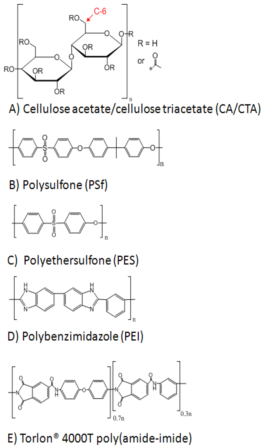
Figure 7.
(A) The chemical structure of cellulose acetate (the red text marks the exocyclic C-6 carbon in one of the rings); (B) the chemical structure of polysulfone; (C) the chemical structure of polyethersulfone; (D) the chemical structure of polybenzimidazole and (E) the proposed structure of Torlon®4000T poly(amide-imide) [73].
2.5. Polyamide
Polyamides (PA) are generally produced by a Shotten-Bauman reaction between an acid chloride and an amine (Reaction (7)). In 1959 Emerson et al. introduced the concept of interfacial polymerization (IP); dissolving the monomers in two immiscible liquids so that the reaction takes place at the liquid-liquid interface [75,76]. The acid chloride is usually dissolved in an organic solvent (e.g., hexane, cyclohexane, isopar) and the amine in water. Cadotte first introduced the method of preparation of TFC-membranes by IP [6].


Table 2 presents some examples of amine-acid chloride combinations used in the preparation of osmotic TFC membranes. IP is described in more detail in Section 3.3.

Table 2.
Some examples of amine-acid chloride combinations used in interfacial polymerization in osmotic membrane fabrication.
| Acid Chloride | Amine | Properties of Polyamide | Reference |
|---|---|---|---|
 Trimesoyl chloride (TMC) |  m-Phenylene diamine (MPD) | TMC-MPD is by far the most common combination of monomers in FO/PRO applications. This polyamide displays excellent flux and salt rejection properties. | [45,77,78,79] |
 p-Phenylene diamine (PPD) | Compared to the TMC-MPD polymer, the TMC-PPD membrane has lower molecular chain mobility. Resulting in a lower flux and higher salt rejection. | [80] | |
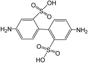 2,2′-Benzidinedisulfonic acid (BDSA) | BDSA was used in addition to MPD and resulted in a more hydrophilic surface. Flux in RO increased as a function of BDSA concentration. Salt rejection increased with BDSA concentration (until 5% BDSA). | [81] | |
 2,6-Diaminetoluene(2,6-DAT) | Membranes synthesized from 2,6-DAT displayed a better chlorine tolerance than TMC-MPD membranes | [82] | |
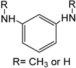 Methylated MPD | Methylated amino groups in MPD increases the average free volume of the polyamide. This resulted in decreased NaCl rejection and increase chlorine resistance. | [83] | |
 3,3,5,5-Biphenyl tetra-acyl chloride (BTEC) |  m-Phenylene diamine (MPD) | This combination gives a three-layer structure of polyamide. The dense middle layer consists of over 86% amide bonds. | [84] |
 Meta: Isophthaloyl chloride (IPC) Para: Terephthaloyl chloride (TPC) | The addition of diacyl chloride (IPC or TPC) in the organic solution resulted in enhanced flux in RO. | [85,86] |
3. Methods
3.1. Asymmetric Cellulose Acetate Membranes
Since the 1960s, when Loeb and Sourirajan prepared the first asymmetric cellulose acetate membranes, asymmetric CA membranes have been used extensively in RO. Hydration Technology Innovations (HTI, Albany, OR) have been providing asymmetric cellulose based membranes for nearly 25 years. A commercial CTA based membrane designed for osmotically driven processes is available from HTI (Figure 8). This membrane contains an embedded support screen and has a dense rejection layer (10–20 μm) far thicker than commercially available composite membranes [87,88]. However, this membrane has performed much better in osmotically driven membrane processes than other commercially available membranes. The hydrophilic nature of the membrane ensures proper wetting and reduced ICP and increased water flux in osmotically driven processes. As a result, this membrane has been extensively used in research of osmotically driven membrane processes. In addition, the hydrophilic cellulose acetate membranes have been reported to have a lower fouling potential than more hydrophilic membranes (e.g., PSf) [60]. This is especially important in PRO where NOM-fouling on the fresh water side is the main fouling problem.
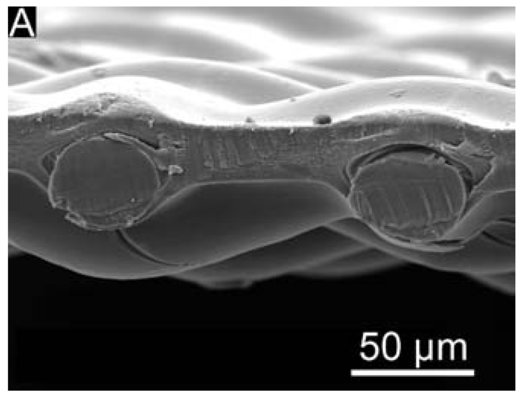
Figure 8.
A cross section SEM micrograph of the commercially available HTI membrane. Picture from [46].
HTI recently reported the development and production of a new thin film forward osmosis membrane. According to a press release from HTI, this membrane is pH tolerant in a 2–12 range, with a salt rejection of 99.3% and has more than double the water flux compared to the previous HTI CTA membrane [88,89].
3.2. Membrane Support Design
The porous support layer in TFC membranes acts as a diffusive boundary layer in osmotically driven membrane processes. This diffusive boundary layer, that is unaffected by stirring, reduces the osmotic driving force across the active layer by ICP [46]. By modifying the support layer, the membrane performance-limiting effects can be reduced. Yip et al. [46] proposed that finger-like structure in the support would reduce ICP. However, a thin sponge layer structure on top would be necessary to enable the formation of a highly selective PA layer. They prepared high performance TFC FO membranes with this structure, as illustrated in Figure 9. These membranes displayed a water flux of 18 LMH and maintained a salt rejection greater than 97%. Tiraferri et al. [43] systematically investigated the properties of TFC membranes prepared using PSf support casted from different polymer solution concentrations. They used a 1-methyl-2-pyrrolidone (NMP, solvent), dimethylformamide (DMF, solvent), water (nonsolvent) and PSf dope solution system. The thermodynamic conditions during phase separation are affected by rates of nonsolvent influx and solvent outflux from the polymer film. Hence, the final membrane morphology depends on the dope solution system. NMP is a more favorable solvent for PSf and have a slower solvent outflux than DMF. Therefore, the velocity of the phase separation can be tailored by controlling the relative amounts of the two solvents. They prepared membranes from a 12% PSf dope solution with varying NMP/DMF ratios and found that when NMP was present the membranes morphology was dominated by macrovoids. These findings were consistent with the theory that NMP in the solvent mixture cause the non-solvent diffusion front to move faster than the polymer vitrification front. Which in turn puts the system under rapid demixing, resulting in the formation of large macrovoids. The membranes prepared by Tiraferri et al. displayed good NaCl rejections in the range 95.8%–99.3% and B-coefficients in the range of 0.25–0.84 LMH. The highest FO water flux was 25.0 LMH, using a 1 M NaCl draw solution.
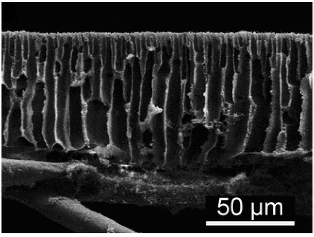
Figure 9.
SEM micrograph of the cross section of a PSf TFC membrane [46].
3.3. Interfacial Polymerization
IP was first introduced by Emerson and Morgan in 1959. They found the Schotten-Bauman reaction to be the basis of this simple, versatile laboratory process [75,76]. Cadotte first introduced the concept of IP-coating on membranes to obtain osmotic TFC membranes [6]. IP produces defect free ultrathin PA-films by a self-sealing and self-terminating mechanism. The method is simple; a support membrane is first soaked in an aqueous amine solution, the excess solution is then removed from the surface to prevent uneven polymerization. The membrane is subsequently soaked in an organic acid chloride solution for a short time to ensure polymerization. Eventually, the membrane is post-treated (curing, chemical reaction, etc.). It is commonly believed that the reaction takes place at the organic side of the interface due to asymmetric solubility. The amine is usually fairly soluble in the organic solvent, whereas the solubility of the acid chloride in water is negligible [90].
IP has been a widely used coating method for TFC membranes since Cadotte first introduced the method. However, until recently little work was done to increase the understanding of the PA-layer’s function. Freger et al. presented a mathematical model for IP and investigated TEM-cross sections of membranes. They concluded that the PA-layer is heterogeneous and cannot be characterized by a single value of parameters such as charge or local polymer density [90,91]. Furthermore, they proposed that IP proceeds in three markedly different kinetic regimes. First the incipient film formation, secondly the slowdown of polymerization and finally diffusion limited growth. The permeability of the polymer and monomer diffusivity will influence the overall composition of the PA-layer [92]. The existence of two oppositely charged layers in the polyamide skin was investigated using uranyl and tungstate-stained samples in TEM. It was proposed that the outmost layer of the PA had a negative charge and that the PA close to the support membrane had an intermediate positive charge [90]. Direct titration experiments revealed the simultaneous presence of negative and positive charged groups on the PA surface of NF membranes [93]. However, Pacheo et al. [94] did not support the proposed theory of the existence of regions of loose PA on the support side of the film [94]. They proposed the existence of a relatively smooth base of dense nodular PA forming the interface with the polysulfone support (Figure 10B). The membrane they tested consisted of a compact base of 30–60 nm PA from which the ridge and valley structure extended outwards [94]. PA-films formed by IP displays a characteristic ridge and valley structure on the surface as illustrated in Figure 10. Ghosh et al. [95] studied the impacts of reaction, curing conditions and support membrane structure in PA-TFC membranes [95,96]. They demonstrated that the support membrane structure played an important role in determining the final characteristics of the polyamide films [95]. Interestingly, they concluded that the PA film thickness and morphology are not intrinsically related to water permeability. This observation indicates that the permeation occurs at the dense inner barrier layer and that the visible ridge and valley surface morphology is just an unfortunate byproduct of the polymerization [96].

Figure 10.
Electron micrographs of the polyamide layer: (A) the ridge and valley structure of the PA surface, micrograph from [94]; (B) TEM cross section of an isolated PA-layer, micrograph from [96]; (C) SEM cross section an on TFC membrane, micrograph from [44].
3.4. Interfacial Polymerization on Hydrophilic Support
Hydrophilic CA/CTA membranes generally have lower water permeability in osmotically driven processes because of their thick selective layer (10–20 μm) [60,88]. Hence, TFC membranes are generally considered the most promising membranes for osmotically driven processes due to their very thin selective layer [44]. However, a wetted hydrophilic support would improve water flux and might reduce internal concentration polarization (ICP) by increasing the wetting of small pores within the support layer [68]. Furthermore, CA/CTA membranes are less prone to absorptive fouling than more hydrophobic membranes [60]. It would be desirable to develop a membrane combining the hydrophilic nature of CA/CTA and the thin selective layer of the TFC. Interfacial polymerization of PA on hydrophilic support is not trivial, as the active layer easily delaminates from the support. Because conventional TFC membranes rely on adhesive forces between the polymers in the support and selective layers to keep the layers together, the polymer choices are limited.
IP on a hydrophilic CTA support was successfully achieved by Alsvik et al. [77,97]. They developed a modified IP method by reacting hydrolyzed CTA with a linking molecule (TMC, succinyl chloride or malonyl chloride) prior to IP, resulting in a covalent bond between the support and the PA layer [77] (Figure 11). Linking molecules could become an important tool in membrane synthesis, increasing the number of possible material choices in TFC membranes.
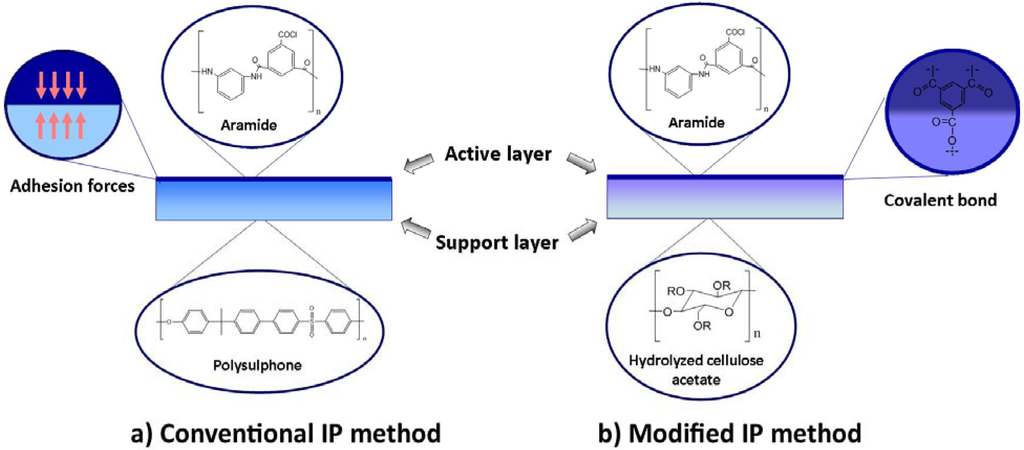
Figure 11.
A comparison of a conventional TFC membrane (a) where the active layer stays on the support by adhesion forces; and the modified IP method (b) with a covalent bond between the active layer and the support layer.
3.5. Electrospun Support
Electrospinning is a process driven by the electrical charges inside or on the surface of a polymeric liquid. An electrospining jet driven by an electrical potential, applied between the polymer solution and a collector, emerges from a needle [98,99]. As the jet stretches and dries, the solidified fibers are collected on an electrically conducting screen of lower potential (Figure 12). This process enables the production of structured polymer fibers with diameters in the range 40–2000 nm at a low cost [99,100]. Although electrospinning is a simple process requiring just a simple laboratory setup, the science behind it is not simple. The process requires the understanding of rheology, polymer solution properties and electrostatics. However, it is a very versatile process and fibers of a range of polymers, sizes and different morphologies can be prepared [98,101].
Bui et al. recently introduced a new membrane preparation method; flat-sheet polyamide composite membranes supported by a nonwoven web of electrospun nanofibers [102]. The nonwoven nanofiber displayed a superior porosity. Furthermore, the high surface porosity reduced the area “masked” by the support layer and therefore increased the effective area of the PA-layer. Electrospun PSf and polyethersulfone (PES) nanofiber supports were coated by IP. PSf supports displayed stronger adhesion to the PA-layer than PES supports. The membranes displayed a water flux two to five times higher than a commercial HTI-CTA osmotic membrane. This new method of designing composite membranes displays great promise for FO applications and might give new insight into the osmotic transport phenomenon [102].
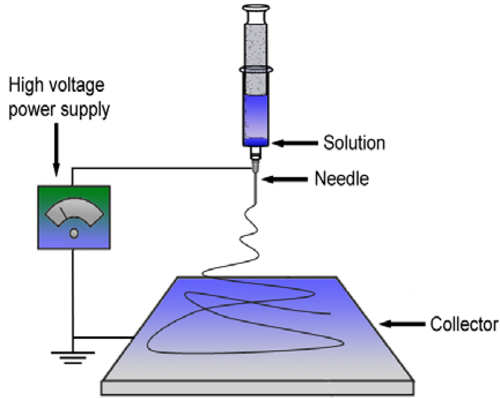
Figure 12.
Illustration of an electrospinning setup. High voltage is applied to a polymer solution in the needle. Subsequently, the electrospinning jet travels towards the collector (lower potential).
3.6. Hollow Fiber Membranes
A hollow fiber membrane is a tubular, self-supporting membrane with a fiber diameter less than 500 μm [40]. These membranes are prepared by phase inversion in a hollow fiber spinning setup. A viscous polymer solution (dope solution) is pumped through a spinneret and the bore solution fluid is pumped through the inner tube of the spinneret. After a short residence time in air or a controlled atmosphere, the fiber is soaked in a coagulation bath [40,103]. Figure 13 illustrates a hollow fiber spinning setup.
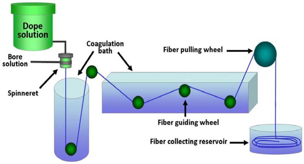
Figure 13.
Illustration of a hollow fiber membrane spinning setup. The dope solution emerges from the spinneret into the coagulation baths and is collected in a reservoir.
The morphology and self-supporting shape of the hollow fibers allows for a wider range of material choices in membrane preparation. Recently, several articles have been published on the formation of hollow fiber membranes specially designed for osmotically driven processes. PBI as material for hollow fiber membranes in osmotically driven processes was first proposed by Wang et al. [70]. PBI hollow fiber membranes cross-linked with p-xylylene dichloride were also prepared. The cross-linked membranes displayed NaCl rejection around 60% and MgCl2 rejection around 95% [104]. Setiawan et al. fabricated FO hollow fiber membranes from Torlon® 40000T poly(amide-imide) (PAI) [75]. The PAI hollow fiber was coated with PEI, resulting in a positively charged NF-like selective layer. The NaCl rejection of the membranes was only 49% and MgCl2 rejection 94% [74]. Fang et al. also prepared double-skinned PAI hollow fiber membranes. However, IP was performed on the inner surface of these membranes to obtain a NF/RO-like active layer [105]. These membranes exhibited a high water flux in FO (41.3 LMH, 2 M NaCl draw) and 85% salt rejection. They also proposed that, compared with single-skinned membranes, the double-skinned membranes offer the advantage of less scaling and ICP (when the feed contains divalent ions) [105].
Shi et al. investigated the relationship between the surface structure of a PES hollow fiber and the performance of the PA layer [79]. They concluded that a substrate with a molecular weight cut off (MWCO) of <300 kDa would be preferable to obtain a good PA layer. Chou et al. prepared polyamide TFC membranes on a commercial hollow fiber PES support with macrovoids [45]. The structure parameters for the membranes were 550–595 μm, comparable with the HTI FO flat-sheet membrane S-value of 575 μm. Sukitpaneenit et al. prepared PA coated macrovoid free PES hollow fibers [48]. These membranes had structure parameters in the range of 219–261 μm and higher flux than the membrane prepared from a support containing macrovoids. Both these membranes displayed a much higher flux than the commercial HTI membrane. The hollow fibers had a water flux in FO mode of 29.5–34.5 LMH compared to a water flux of 13.0 LMH of the HTI membrane (2 M NaCl draw). In PRO mode the water fluxes of the hollow fibers were in the range of 57.1–68.0 LMH and the HTI had a water flux of 11.2 LMH (2 M NaCl draw). Sukitpaneenit et al. proposed that a macrovoid free hollow fiber with a highly sponge like structure could reduce ICP, and thus enhance water flux [48]. Investigations on fouling of PES-PA hollow fibers indicated a high fouling potential. However, a relatively dense membrane surface seemed to reduce the fouling potential of the hollow fiber [79].
3.7. Support Membrane Modification to Increase Hydrophilicity
As discussed in Section 0, improved wetting of support membrane will increase water flux and reduce ICP in osmotically driven membrane processes [69]. Arena et al. [106] coated the support layers of two commercially available RO membranes (BW30 and SW30-XLE from Dow) with polydopamine (PDA) to increase their hydrophilicity. Polydopamine is a bio-inspired polymer capable of adhering to substrates in water without surface preparation. An in-situ polymerization/precipitation of dopamine hydrochloride was performed on the two membranes. Both membranes, displayed improved osmotic water fluxes (PRO mode). The osmotic flux of the SW30-XLE membrane increased by ~20% after the PDA-treatment [106].
3.8. New Trends in Composite Membrane Design
The progress in FO/PRO membrane development depends on that new design strategies of the materials will improve the performance of these membranes. One strategy is to functionalize the membrane surface and/or embedding functionalized nanoparticles in the polymer. In this way the surface may be tailored to possess properties, which may both decrease fouling and enhance water flux. As an example, Tiraferri et al. [107] investigated a polyamide FO-membrane with optimized surface properties by using silica nanoparticles coated with very hydrophilic ligands, and demonstrated that a barrier was formed reducing foulant adhesion. Other types of surface coatings and functionalization can be used to immobilize small particles as well as kill harmful organisms (bacteria) in the feed solution. Another aspect is the need for re-engineering the support structure of the membranes to make the membrane more suitable to withstand stress. In general, the use of nanoparticles embedded in the structures, such as carbon nanoparticles or cellulose fibrils, will improve the mechanical strength of the support membrane. Increased mechanical strength can also be achieved by adding electrospun nanofibers in a thin-film composite membrane as documented by Hoover et al. [108]. The membrane will then be more suitable for application in harsh environment (i.e., PRO for saline power production).
3.9. Draw Solutions (DS) an Important Variable to Consider along with the Material
There is an important aspect related to the FO and PRO processes which has only been briefly mentioned in the Introduction of the current paper; that is the importance of the draw solution (DS) for a successful process. The performance of the process will not only depend on the material, but will greatly depend on the selection of a suitable DS as this is the main source of the driving force. It is hence of great importance not only to evaluate the type of material, but also which DS will be the most suitable for a specific application. In the many review papers available for FO and PRO processes, the DS is discussed with sample processes, as indicated in the Introduction part of the current paper. However, only few papers discuss the alternative choices there may be for the DS. Recovery, regeneration and recycling of the DS are major challenges for these processes as it very quickly will add significant costs to the process. Each of the DS exhibits different characteristics with respect to osmotic pressure, water solubility, viscosity or molecular weight. The standard solutes which are extensively used are the various inorganic compounds; mainly electrolyte solutions [109,110]. Later also organic compounds (glucose, fructose) have been tested, especially for seawater desalination [111]. Then more recently, DS with nanoparticles, in particular hydrophilic magnetic nanoparticles, has become an area of great interest [21,112]. Their main advantage is their extremely high surface area-to volume ratio and their bigger size compared to salts and organic molecules. Other DS choices may be the use of concentrated brine from RO-processes, hence this may lower the energy costs for a desalination process. There are numerous other choices for DS which are being investigated: ionic polymer hydrogel particles, dendrimers and colloidal systems such as micellar solutions. A nice overview and discussion of the various choices for draw solutions suitable for FO and PRO processes is presented in the review paper of Checkli et al. [113], likewise in the paper of Chung et al. [36] a review of emerging FO technologies is presented.
4. Conclusions and Outlook
The FO and PRO processes are not only considered for desalination and water purification, but has a big potential also within energy production, biomedical applications and food processing. In the current paper, we have reviewed the materials used for preparation of suitable FO and PRO membranes as well as methods for preparing the membranes.
At the present time, only few membranes for osmotically driven processes are commercially available. Membranes for osmotically driven processes should have large water permeability (high A), low reverse solute permeation (low B) and low structure parameter (low S). ICP and fouling are considerable problems in osmotically driven processes. Several novel membrane material choices and design strategies for FO/PRO membranes have emerged the last few years: preparation of TFC membranes with a customized PSf support, electorspun support, TFC membranes on hydrophilic support, hollow fiber FO/PRO membranes and membranes with modified support. Depending on the system, the membranes may be functionalized for enhanced water flux and/or reduce potential fouling These new membranes display promising results in lab scale and the next challenge will be to investigate upscaling and durability of the novel membranes. The progress in FO/PRO membrane development the last few years shows that new design strategies and materials can improve the performance of the membranes. Last but not least, it should be remembered that the choice of draw solution will play a very important role in combination with the material itself in order to have a successful, low energy demanding process where the DS can easily be regenerated.
Acknowledgments
The authors acknowledge the Norwegian Research Council, Statkraft, Statoil and Aqualyng for financial support.
References and Notes
- Glater, J. The early history of reverse osmosis membrane development. Desalination 1998, 117, 297–309. [Google Scholar] [CrossRef]
- Nollet, A. Lecons de Physique Experimentale; Chez les Frères Guérin: Paris, France, 1748. [Google Scholar]
- Traube, M. Experimente zur Theorie der Zellenbildung und Endosmose. Archiv für Anatomie Physologie und wisserschlaftliche Med. 1867, 87–165. [Google Scholar]
- Loeb, S. The loeb-sourirajan membrane: How it came about. In Synthetic Membranes; American Chemical Society: Washington, DC, USA, 1981; Volume 153, pp. 1–9. [Google Scholar]
- Cadotte, J.E. Reverse Osmosis Membrane. U.S. Patent 4,039,440, 2 August 1977. [Google Scholar]
- Cadotte, J.E. Interfacially Synthesized Reverse Osmosis Membrane. U.S. Patent 4,277,344, 7 July 1981. [Google Scholar]
- Cadotte, J.E. Reverse Osmosis Membrane. U.S. Patent 4,259,183, 31 March 1981. [Google Scholar]
- Cadotte, J.E.; Petersen, R.J.; Larson, R.E.; Erickson, E.E. A new thin-film composite seawater reverse osmosis membrane. Desalination 1980, 32, 25–31. [Google Scholar] [CrossRef]
- Larson, R.E.; Cadotte, J.E.; Petersen, R.J. The FT-30 seawater reverse osmosis membrane—Element test results. Desalination 1981, 38, 473–483. [Google Scholar] [CrossRef]
- ACS Scifinder Home Page. Available online: http://www.cas.org/products/scifinder (accessed on 11 March 2013).
- Sidney, L. Production of energy from concentrated brines by pressure-retarded osmosis: I. Preliminary technical and economic correlations. J. Membr. Sci. 1976, 1, 49–63. [Google Scholar] [CrossRef]
- Loeb, S.; van Hessen, F.; Shahaf, D. Production of energy from concentrated brines by pressure-retarded osmosis: II. Experimental results and projected energy costs. J. Membr. Sci. 1976, 1, 249–269. [Google Scholar] [CrossRef]
- Statkraft Home Page. Available online: http://www.statkraft.no/jobb-og-karriere/ (accessed on 11 March 2013).
- Skilhagen, S.E.; Dugstad, J.E.; Aaberg, R.J. Osmotic power—Power production based on the osmotic pressure difference between waters with varying salt gradients. Desalination 2008, 220, 476–482. [Google Scholar] [CrossRef]
- Batchelder, G.W. Process for the Demineralization of Water. U.S. Patent 3,171,799, 3 February 1965. [Google Scholar]
- Glew, D.N. Process for Liquid Recovery and Solution Concentration. U.S. Patent 3,216,930, 11 September 1965. [Google Scholar]
- Frank, B.S. Desalination of Sea Water. U.S. Patent 3,670,897, 20 June 1972. [Google Scholar]
- Kravath, R.E.; Davis, J.A. Desalination of sea water by direct osmosis. Desalination 1975, 16, 151–155. [Google Scholar] [CrossRef]
- Stache, K. Apparatus for Transforming Sea Water, Brackish Water, Polluted Water or the Like into a Nutritious Drink by Means of Osmosis. U.S. Patent 4,879,030, 11 July 1989. [Google Scholar]
- Yaeli, J. Method and Apparatus for Processing Liquid Solutions of Suspensions Particularly Useful in the Desalination of Saline Water. U.S. Patent 5,098,575, 24 March 1992. [Google Scholar]
- McGinnis, R. Osmotic Desalination Process. U.S. Patent 7,560,029 B2, 14 July 2009. [Google Scholar]
- Ling, M.M.; Wang, K.Y.; Chung, T.-S. Highly water-soluble magnetic nanoparticles as novel draw solutes in forward osmosis for water reuse. Ind. Eng. Chem. Res. 2010, 49, 5869–5876. [Google Scholar] [CrossRef]
- McCutcheon, J.R.; McGinnis, R.L.; Elimelech, M. A novel ammonia-carbon dioxide forward (direct) osmosis desalination process. Desalination 2005, 174, 1–11. [Google Scholar] [CrossRef]
- Cath, T.Y.; Childress, A.E.; Elimelech, M. Forward osmosis: Principles, applications, and recent developments. J. Membr. Sci. 2006, 281, 70–87. [Google Scholar] [CrossRef]
- Cath, T.Y.; Gormly, S.; Beaudry, E.G.; Flynn, M.T.; Adams, V.D.; Childress, A.E. Membrane contactor processes for wastewater reclamation in space: Part I. Direct osmotic concentration as pretreatment for reverse osmosis. J. Membr. Sci. 2005, 257, 85–98. [Google Scholar] [CrossRef]
- Hydration Technology Innovations Home Page. Available online: http://www.htiwater.com/ (accessed on 11 March 2013).
- Dalla Rosa, M.; Giroux, F. Osmotic treatments (OT) and problems related to the solution management. J. Food Eng. 2001, 49, 223–236. [Google Scholar] [CrossRef]
- Wright, J.C.; Johnson, R.M.; Yum, S.I. Duros® osmotic pharmaceutical systems for parenteral & site-directed therapy. Drug Dev. Deliv. 2003, 3, 64–73. [Google Scholar]
- Holloway, R.W.; Childress, A.E.; Dennett, K.E.; Cath, T.Y. Forward osmosis for concentration of anaerobic digester centrate. Water Res. 2007, 41, 4005–4014. [Google Scholar] [CrossRef]
- Elimelech, M.; Phillip, W.A. The future of seawater desalination: Energy, technology, and the environment. Science 2011, 333, 712–717. [Google Scholar] [CrossRef]
- Zhao, S.; Zou, L.; Tang, C.Y.; Mulcahy, D. Recent developments in forward osmosis: Opportunities and challenges. J. Membr. Sci. 2012, 396, 1–21. [Google Scholar] [CrossRef]
- Chung, T.-S.; Zhang, S.; Wang, K.Y.; Su, J.; Ling, M.M. Forward osmosis processes: Yesterday, today and tomorrow. Desalination 2012, 287, 78–81. [Google Scholar] [CrossRef]
- Hoover, L.A.; Phillip, W.A.; Tiraferri, A.; Yip, N.Y.; Elimelech, M. Forward with osmosis: Emerging applications for greater sustainability. Environ. Sci. Technol. 2011, 45, 9824–9830. [Google Scholar]
- Achilli, A.; Cath, T.Y.; Childress, A.E. Power generation with pressure retarded osmosis: An experimental and theoretical investigation. J. Membr. Sci. 2009, 343, 42–52. [Google Scholar] [CrossRef]
- Achilli, A.; Cath, T.Y.; Marchand, E.A.; Childress, A.E. The forward osmosis membrane bioreactor: A low fouling alternative to mbr processes. Desalination 2009, 239, 10–21. [Google Scholar] [CrossRef]
- Chung, T.-S.; Li, X.; Ong, R.C.; Ge, Q.; Wang, H.; Han, G. Emerging forward osmosis (FO) technologies and challenges ahead for clean water and clean energy applications. Curr. Opin. Chem. Eng. 2012, 1, 246–257. [Google Scholar] [CrossRef]
- Achilli, A.; Childress, A.E. Pressure retarded osmosis: From the vision of sidney loeb to the first prototype installation—Review. Desalination 2010, 261, 205–211. [Google Scholar] [CrossRef]
- Zhang, S.; Fu, F.; Chung, T.-S. Substrate modifications and alcohol treatment on thin film composite membranes for osmotic power. Chem. Eng. Sci. 2013, 87, 40–50. [Google Scholar] [CrossRef]
- Greentech Media Home Page. Available online: http://www.greentechmedia.com/ (accessed on 11 March 2013).
- Mulder, M. Basic Principles of Membrane Technology; Kluver Academic Publishers: Dordrecht, The Netherlands, 1996. [Google Scholar]
- Phillip, W.A.; Yong, J.S.; Elimelech, M. Reverse draw solute permeation in forward osmosis: Modeling and experiments. Environ. Sci. Technol. 2010, 44, 5170–5176. [Google Scholar] [CrossRef]
- Loeb, S.; Titelman, L.; Korngold, E.; Freiman, J. Effect of porous support fabric on osmosis through a loeb-sourirajan type asymmetric membrane. J. Membr. Sci. 1997, 129, 243–249. [Google Scholar]
- Tiraferri, A.; Yip, N.Y.; Phillip, W.A.; Schiffman, J.D.; Elimelech, M. Relating performance of thin-film composite forward osmosis membranes to support layer formation and structure. J. Membr. Sci. 2011, 367, 340–352. [Google Scholar] [CrossRef]
- Gerstandt, K.; Peinemann, K.V.; Skilhagen, S.E.; Thorsen, T.; Holt, T. Membrane processes in energy supply for an osmotic power plant. Desalination 2008, 224, 64–70. [Google Scholar] [CrossRef]
- Chou, S.; Shi, L.; Wang, R.; Tang, C.Y.; Qiu, C.; Fane, A.G. Characteristics and potential applications of a novel forward osmosis hollow fiber membrane. Desalination 2010, 261, 365–372. [Google Scholar] [CrossRef]
- Yip, N.Y.; Tiraferri, A.; Phillip, W.A.; Schiffman, J.D.; Elimelech, M. High performance thin-film composite forward osmosis membrane. Environ. Sci. Technol. 2010, 44, 3812–3818. [Google Scholar]
- Wei, J.; Qiu, C.; Tang, C.Y.; Wang, R.; Fane, A.G. Synthesis and characterization of flat-sheet thin film composite forward osmosis membranes. J. Membr. Sci. 2011, 372, 292–302. [Google Scholar] [CrossRef]
- Sukitpaneenit, P.; Chung, T.-S. High performance thin-film composite forward osmosis hollow fiber membranes with macrovoid-free and highly porous structure for sustainable water production. Environ. Sci. Technol. 2012, 46, 7358–7365. [Google Scholar] [CrossRef]
- Wang, R.; Shi, L.; Tang, C.Y.; Chou, S.; Qiu, C.; Fane, A.G. Characterization of novel forward osmosis hollow fiber membranes. J. Membr. Sci. 2010, 355, 158–167. [Google Scholar] [CrossRef]
- Gray, G.T.; McCutcheon, J.R.; Elimelech, M. Internal concentration polarization in forward osmosis: Role of membrane orientation. Desalination 2006, 197, 1–8. [Google Scholar] [CrossRef]
- McCutcheon, J.R.; Elimelech, M. Influence of concentrative and dilutive internal concentration polarization on flux behavior in forward osmosis. J. Membr. Sci. 2006, 284, 237–247. [Google Scholar] [CrossRef]
- Lee, K.L.; Baker, R.W.; Lonsdale, H.K. Membranes for power generation by pressure-retarded osmosis. J. Membr. Sci. 1981, 8, 141–171. [Google Scholar] [CrossRef]
- Hancock, N.T.; Cath, T.Y. Solute coupled diffusion in osmotically driven membrane processes. Environ. Sci. Technol. 2009, 43, 6769–6775. [Google Scholar] [CrossRef]
- Hancock, N.T.; Phillip, W.A.; Elimelech, M.; Cath, T.Y. Bidirectional permeation of electrolytes in osmotically driven membrane processes. Environ. Sci. Technol. 2011, 45, 10642–10651. [Google Scholar] [CrossRef]
- Yong, J.S.; Phillip, W.A.; Elimelech, M. Coupled reverse draw solute permeation and water flux in forward osmosis with neutral draw solutes. J. Membr. Sci. 2012, 392–393, 9–17. [Google Scholar]
- Zelman, A. Membrane permeability: Generalization of the reflection coefficient method of describing volume and solute flows. Biophys. J. 1972, 12, 414–419. [Google Scholar] [CrossRef]
- Amy, G. Fundamental understanding of organic matter fouling of membranes. Desalination 2008, 231, 44–51. [Google Scholar] [CrossRef]
- Rana, D.; Matsuura, T. Surface modifications for antifouling membranes. Chem. Rev. 2010, 110, 2448–2471. [Google Scholar] [CrossRef]
- Seidel, A.; Elimelech, M. Coupling between chemical and physical interactions in natural organic matter (NOM) fouling of nanofiltration membranes: Implications for fouling control. J. Membr. Sci. 2002, 203, 245–255. [Google Scholar] [CrossRef]
- Thorsen, T. Concentration polarisation by natural organic matter (NOM) in NF and UF. J. Membr. Sci. 2004, 233, 79–91. [Google Scholar] [CrossRef]
- Mi, B.; Elimelech, M. Gypsum scaling and cleaning in forward osmosis: Measurements and mechanisms. Environ. Sci. Technol. 2010, 44, 2022–2028. [Google Scholar] [CrossRef]
- Lee, S.; Boo, C.; Elimelech, M.; Hong, S. Comparison of fouling behavior in forward osmosis (FO) and reverse osmosis (RO). J. Membr. Sci. 2010, 365, 34–39. [Google Scholar] [CrossRef]
- Boo, C.; Lee, S.; Elimelech, M.; Meng, Z.; Hong, S. Colloidal fouling in forward osmosis: Role of reverse salt diffusion. J. Membr. Sci. 2012, 390–391, 277–284. [Google Scholar]
- Mi, B.; Elimelech, M. Chemical and physical aspects of organic fouling of forward osmosis membranes. J. Membr. Sci. 2008, 320, 292–302. [Google Scholar] [CrossRef]
- Liu, Y.; Mi, B. Combined fouling of forward osmosis membranes: Synergistic foulant interaction and direct observation of fouling layer formation. J. Membr. Sci. 2012, 407–408, 136–144. [Google Scholar] [CrossRef]
- Mi, B.; Elimelech, M. Organic fouling of forward osmosis membranes: Fouling reversibility and cleaning without chemical reagents. J. Membr. Sci. 2010, 348, 337–345. [Google Scholar] [CrossRef]
- Carraher, C.E. Polymer Chemistry, 6th ed; Marcel Dekker: New York, NY, USA, 2003. [Google Scholar]
- McCutcheon, J.R.; Elimelech, M. Influence of membrane support layer hydrophobicity on water flux in osmotically driven membrane processes. J. Membr. Sci. 2008, 318, 458–466. [Google Scholar] [CrossRef]
- Saunders, K.J. Organic Polymer Chemistry, 2nd ed; Chapman Hall: New York, NY, USA, 1988. [Google Scholar]
- Wang, K.Y.; Chung, T.-S.; Qin, J.-J. Polybenzimidazole (pbi) nanofiltration hollow fiber membranes applied in forward osmosis process. J. Membr. Sci. 2007, 300, 6–12. [Google Scholar] [CrossRef]
- Sawyer, L.C.; Jones, R.S. Observations on the structure of first generation polybenzimidazole reverse osmosis membranes. J. Membr. Sci. 1984, 20, 147–166. [Google Scholar] [CrossRef]
- Solvay Specicality Polymers. Technical Data Sheet, Torlon®4000t. Available online: http://catalog.ides.com/datasheet.aspx?I=42041&FMT=PDF&E=135275 (accessed on 11 March 2013).
- Robertson, G.P.; Guiver, M.D.; Yoshikawa, M.; Brownstein, S. Structural determination of torlon® 4000t polyamide–imide by nmr spectroscopy. Polymer 2004, 45, 1111–1117. [Google Scholar] [CrossRef]
- Setiawan, L.; Wang, R.; Li, K.; Fane, A.G. Fabrication of novel poly(amide–imide) forward osmosis hollow fiber membranes with a positively charged nanofiltration-like selective layer. J. Membr. Sci. 2011, 369, 196–205. [Google Scholar] [CrossRef]
- Wittbecker, E.L.; Morgan, P.W. Interfacial polycondensation. I. J. Polym. Sci. 1959, 40, 289–297. [Google Scholar] [CrossRef]
- Morgan, P.W.; Kwolek, S.L. Interfacial polycondensation. II. Fundamentals of polymer formation at liquid interfaces. J. Polym. Sci. 1959, 40, 299–327. [Google Scholar] [CrossRef]
- Alsvik, I.L.; Hägg, M.B. Preparation of thin film composite membranes with polyamide film on hydrophilic supports. J. Membr. Sci. 2013, 428, 225–231. [Google Scholar] [CrossRef]
- Nilsen, T.-N.; Alsvik, I.L. Thin Film Composites. WO Patent 2011/152735, 8 December 2011. [Google Scholar]
- Shi, L.; Chou, S.R.; Wang, R.; Fang, W.X.; Tang, C.Y.; Fane, A.G. Effect of substrate structure on the performance of thin-film composite forward osmosis hollow fiber membranes. J. Membr. Sci. 2011, 382, 116–123. [Google Scholar] [CrossRef]
- Juhn Roh, I. Effect of the physicochemical properties on the permeation performance in fully aromatic crosslinked polyamide thin films. J. Appl. Polym. Sci. 2003, 87, 569–576. [Google Scholar] [CrossRef]
- Baroña, G.N.B.; Lim, J.; Jung, B. High performance thin film composite polyamide reverse osmosis membrane prepared via m-phenylenediamine and 2,2′-benzidinedisulfonic acid. Desalination 2012, 291, 69–77. [Google Scholar] [CrossRef]
- Son, S.H.; Jegal, J. Preparation and characterization of polyamide reverse-osmosis membranes with good chlorine tolerance. J. Appl. Polym. Sci. 2011, 120, 1245–1252. [Google Scholar] [CrossRef]
- Shintani, T.; Shimazu, A.; Yahagi, S.; Matsuyama, H. Characterization of methyl-substituted polyamides used for reverse osmosis membranes by positron annihilation lifetime spectroscopy and md simulation. J. Appl. Polym. Sci. 2009, 113, 1757–1762. [Google Scholar] [CrossRef]
- Liu, Y.; He, B.; Li, J.; Sanderson, R.D.; Li, L.; Zhang, S. Formation and structural evolution of biphenyl polyamide thin film on hollow fiber membrane during interfacial polymerization. J. Membr. Sci. 2011, 373, 98–106. [Google Scholar] [CrossRef]
- Yu, S.; Liu, M.; Liu, X.; Gao, C. Performance enhancement in interfacially synthesized thin-film composite polyamide-urethane reverse osmosis membrane for seawater desalination. J. Membr. Sci. 2009, 342, 313–320. [Google Scholar]
- Zhou, Y.; Yu, S.; Liu, M.; Chen, H.; Gao, C. Effect of mixed crosslinking agents on performance of thin-film-composite membranes. Desalination 2006, 192, 182–189. [Google Scholar]
- Herron, J. Asymmetric Forward Osmosis Membranes. U.S. Patent 7,445,712, 4 November 2008. [Google Scholar]
- Herron, J. Two-Layer Membrane. U.S. Patent 0,175,300 A1, 12 July 2012. [Google Scholar]
- Smoke, J. HTI’s New Thin Film Forward Osmosis Membrane in Production. Available online: http://www.htiwater.com/news/press-room/content/2012/press-HTI-HTIThinFilmMembrane042512.pdf (accessed on 11 March 2013).
- Freger, V. Nanoscale heterogeneity of polyamide membranes formed by interfacial polymerization. Langmuir 2003, 19, 4791–4797. [Google Scholar] [CrossRef]
- Freger, V.; Srebnik, S. Mathematical model of charge and density distributions in interfacial polymerization of thin films. J. Appl. Polym. Sci. 2003, 88, 1162–1169. [Google Scholar] [CrossRef]
- Freger, V. Kinetics of film formation by interfacial polycondensation. Langmuir 2005, 21, 1884–1894. [Google Scholar] [CrossRef]
- Schaep, J.; Vandecasteele, C. Evaluating the charge of nanofiltration membranes. J. Membr. Sci. 2001, 188, 129–136. [Google Scholar] [CrossRef]
- Pacheco, F.A.; Pinnau, I.; Reinhard, M.; Leckie, J.O. Characterization of isolated polyamide thin films of ro and nf membranes using novel tem techniques. J. Membr. Sci. 2010, 358, 51–59. [Google Scholar] [CrossRef]
- Ghosh, A.K.; Hoek, E.M.V. Impacts of support membrane structure and chemistry on polyamide–polysulfone interfacial composite membranes. J. Membr. Sci. 2009, 336, 140–148. [Google Scholar] [CrossRef]
- Ghosh, A.K.; Jeong, B.-H.; Huang, X.; Hoek, E.M.V. Impacts of reaction and curing conditions on polyamide composite reverse osmosis membrane properties. J. Membr. Sci. 2008, 311, 34–45. [Google Scholar] [CrossRef]
- Alsvik, I.L.; Katherine, Z.; Elimelech, M.; Hägg, M.-B. Polyamide formation on a cellulose triacetate support for osmotic membranes: Effect of linking molecules on membrane performance. Desalination 2013, 312, 2–9. [Google Scholar] [CrossRef]
- Ramakrishna, S. Introduction to Electrospinning and Nanofibers; World Scientific Publishing Co.: River Edge, NJ, USA, 2005. [Google Scholar]
- Reneker, D.H.; Chun, I. Nanometre diameter fibres of polymer, produced by electrospinning. Nanotechnology 1996, 7, 216. [Google Scholar] [CrossRef]
- He, J.-H. Electrospun Nanofibers and Their Applications; Smithers Rapra: Shrewsbury, UK, 2008. [Google Scholar]
- Stranger, J.; Tucker, N.; Staiger, M. Electrospinning; Smithers Rapra: Shrevsbury, UK, 2009. [Google Scholar]
- Bui, N.-N.; Lind, M.L.; Hoek, E.M.V.; McCutcheon, J.R. Electrospun nanofiber supported thin film composite membranes for engineered osmosis. J. Membr. Sci. 2011, 385–386, 10–19. [Google Scholar]
- Clausi, D.T.; Koros, W.J. Formation of defect-free polyimide hollow fiber membranes for gas separations. J. Membr. Sci. 2000, 167, 79–89. [Google Scholar] [CrossRef]
- Wang, K.Y.; Yang, Q.; Chung, T.-S.; Rajagopalan, R. Enhanced forward osmosis from chemically modified polybenzimidazole (pbi) nanofiltration hollow fiber membranes with a thin wall. Chem. Eng. Sci. 2009, 64, 1577–1584. [Google Scholar] [CrossRef]
- Fang, W.; Wang, R.; Chou, S.; Setiawan, L.; Fane, A.G. Composite forward osmosis hollow fiber membranes: Integration of RO- and NF-like selective layers to enhance membrane properties of anti-scaling and anti-internal concentration polarization. J. Membr. Sci. 2012, 394–395, 140–150. [Google Scholar]
- Arena, J.T.; McCloskey, B.; Freeman, B.D.; McCutcheon, J.R. Surface modification of thin film composite membrane support layers with polydopamine: Enabling use of reverse osmosis membranes in pressure retarded osmosis. J. Membr. Sci. 2011, 375, 55–62. [Google Scholar] [CrossRef]
- Tiraferri, A.; Kang, Y.; Gianellis, E.P.; Elimelech, M. Highly hydrophilic thin-film composite forward osmosis membranes functionalized with surface-tailored nanoparticles. ACS Appl. Mater. Interf. 2012, 4, 5044–5053. [Google Scholar] [CrossRef]
- Hoover, L.A.; Schiffman, J.D.; Elimelech, M. Nanofibers in thin-film composite membrane support layers: Enabling expanded application of forward and pressure retarded osmosis. Desalination 2013, 308, 73–81. [Google Scholar] [CrossRef]
- Phuntsho, S.; Shon, H.K.; Hong, S.; Lee, S.; Vigneswaran, S. A novel low energy fertilizer driven forward osmosis desalination for direct fertigation: Evaluation the performance of fertilizer draw solutions. J. Membr. Sci. 2011, 375, 172–181. [Google Scholar] [CrossRef]
- Achili, A.; Cath, T.Y.; Childress, A.E. Selection of inorganic-based draw solutions for forward osmosis applications. J. Membr. Sci. 2010, 364, 233–241. [Google Scholar] [CrossRef]
- Ngu, H.Y.; Tang, W. Forward (direct) osmosis: A novel and prospective process for brine control. Water Environ. Found. 2006, 4345–4352. [Google Scholar]
- Ling, M.M.; Chung, T.-S. Novel dual–stage FO system for sustainable protein enrichment using nanoparticles as intermediate draw solutes. J. Membr. Sci. 2011, 372, 201–209. [Google Scholar] [CrossRef]
- Checkli, L.; Phuntsho, S.; Shon, H.K.; Vigneswaran, S.; Kandasamy, J.; Chahan, A. A review of draw solutes in forward osmosis process and their use in modern applications. Desalin. Water Treat. 2012, 43, 167–184. [Google Scholar] [CrossRef]
© 2013 by the authors; licensee MDPI, Basel, Switzerland. This article is an open access article distributed under the terms and conditions of the Creative Commons Attribution license (http://creativecommons.org/licenses/by/3.0/).