Abstract
This paper addresses the challenge of producing lightweight, low-cost, and highly functional devices and components for the electronics industry. To tackle this issue, functionally graded materials consisting of a polymer base and a metallic conductive layer were developed. Technology for producing functionally graded materials was created and optimized. To evaluate the influence of key process parameters on the functional and mechanical properties of the composites, three-dimensional models were constructed and mathematical equations were formulated. The continuity and thickness of the surface layer were examined, the dielectric properties of the polymer material were measured, the resistance of the conductive surface layer was assessed, and adhesion tests of the surface layer were performed.
1. Introduction
The challenge of producing lightweight, low-cost, and highly functional devices and components is critical to modern industry. Addressing this challenge requires combining multiple materials with different properties and adapting them to various device elements or components within a simple manufacturing process. One common material combination used to achieve this goal involves metals and polymers, which are among the most frequently employed functionally graded materials [1,2,3,4,5]. These materials find applications in such fields as aerospace, automotive, instrumentation, electronics, and medicine [6,7]. Polymer materials are widely used due to their light weight, flexibility, ease of fabrication, and low cost. With the recent advances in materials science, it is essential to have materials with high strength and ductility. These mechanical properties can be achieved by using materials with a gradient structure. In the review [8], some methods for creating gradient structures, such as SMAT, SMGT, RASP, USP and Torsion, are briefly described. Using these methods, the evolution of the microstructure, strength and ductility of various materials is considered. In the work [9], the authors summarize data on gradient polymer materials with a wide range of mechanical, optical, and other properties. The term “type-one gradient materials” refers to materials with a smoothly changing elastic modulus in the range of 3–2000 MPa with no layers and interfaces, gluing, heat sealing, etc. in the material. The term “type-two gradient materials” refers to materials with a sharply changing elastic modulus and a transition zone between the glassy and highly elastic states. In the work [10], gradient materials were obtained by mixing mixtures of polyacrylic acid/sodium salt and its copolymers with acrylamide and Fe and Ce particles in an applied electric field. The authors of the article [11] developed printing strategies for multiple copper-based composites and multi-component gradient materials. This allowed us to create multiple metallic and non-metallic compounds, as well as multi-gradient materials with different compositions and structures with simultaneous gradient properties.
Additive manufacturing technologies offer significant potential for creating complex objects with multiple functions. In particular, these technologies can be used to produce embedded electronics, 3D structural electronics, conformal electronics, stretchable electronics, and more [7,12,13]. By using additive manufacturing to fabricate complex 3D geometries from multiple materials, it becomes possible to create devices that are unattainable through traditional 2D printing methods originally developed for the graphics industry. Examples include multilayer printed circuit boards, electrical connectors, 3D antennas, mission-specific satellite components, 3D structures with embedded electronics, and batteries. The field of 3D printed electronics enables low-volume production of highly complex and customizable electronic structures while reducing material waste, energy consumption, prototyping time, and costs compared to conventional methods [14,15,16,17,18,19].
The functionality of products can be enhanced by applying functional coatings to their surfaces. Currently, a wide variety of methods are used for this purpose. They include physical vapor deposition (PVD), chemical vapor deposition (CVD), spin coating, dip coating, chemical synthesis, vacuum deposition, flame and arc spraying, electrolytic deposition, chemical coating, and others. However, PVD, CVD, and thermal spray processes operate at high deposition temperatures, which can sometimes exceed the melting point of polymer substrates. Operating temperatures for CVD are approximately 200–600 °C for PVD, 800–1100 °C, while thermal spray methods can reach up to 1000 °C [20,21,22]. These methods also involve significant setup and operating costs. Additionally, the electrolytic process is unsuitable for applying coatings to non-metallic substrates [23]. In comparison, chemical vapor deposition (CVD) is a feasible option, as it can deposit layers of metals or metallic compounds onto plastics and polymers. This process offers several advantages, like uniform coating application on complex geometric contours, low deposition temperatures well below the melting point of plastics and polymers, good wear and corrosion resistance, low cost, and ability to impart electrical conductivity to the surface [24,25,26,27].
Polymer modification, including surface metallization with metallic layers, has been widely used in industry and science since its inception [28,29,30,31]. In the early years of metallization technology, plastic metallization was primarily employed to enhance decorative properties. Later, with the advancement of metallization methods, attempts were made to improve the technical properties of polymers. Consequently, plastic metallization has become increasingly prevalent in electronics and micromechanics. The development of printed circuit boards using various types of polymer materials has marked a significant breakthrough in the technological industry [32,33,34,35].
Electroless plating is a promising method for metallizing plastic 3D-printed details. However, current techniques depend on surface activation using costly metal catalysts such as palladium [36,37]. Therefore, it is essential to explore alternative solutions for metallizing polymeric materials. Electroless plating is an autocatalytic process that reduces metal ions from a solution with a chemical reducing agent. This method is highly efficient on catalytically active surfaces and does not require complex electrochemical equipment. Nevertheless, this technology relies on noble metals (Pd, Pt) as catalysts, uses highly toxic reagents during surface activation, and is unable to selectively deposit coatings without additional masking technologies [38,39,40]. Despite these drawbacks, electroless plating remains a viable option because it does not require control of current density or uniform electrode distribution. It is most commonly used to form conductive sublayers for subsequent galvanic metal deposition [41,42,43].
The metallization of polymer details produced via 3D printing presents several technological challenges due to the unique additive manufacturing characteristics. Key issues include increased surface layer porosity, pronounced anisotropy in mechanical properties, low adhesion strength at the metal-polymer interface, and unpredictable material behavior during chemical processing. As studies have demonstrated [44,45,46], the combined effect of these factors significantly degrades the quality of metallic coatings. Incorrect selection of process parameters can lead to defects such as selective metal deposition in surface imperfections, coating delamination or intense gas evolution at the interface [47,48]. These issues significantly undermine the benefits of additive manufacturing technologies, despite their exceptional flexibility and extensive shaping capabilities. Nevertheless, the combination of additive manufacturing and metallization techniques opens new prospects for rapid prototyping of functional devices.
After reviewing a number of studies [49,50,51], we decided to focus on SLA printing when developing metallization technology. It enables the production of miniature, complex-shaped components for the electronics industry.
Thus, improving metallization methods for additively manufactured details is a critical scientific and technical challenge. Addressing this challenge will broaden the application of additive technologies from experimental prototyping to mass production of functional devices.
In this study, 3D printing and chemical metallization technologies were developed. They encompass sensitization, activation, and copper plating processes. The technology utilizes volumetric resin sensitization with tannin, thereby eliminating the need for costly surface activators such as platinum and palladium, as well as avoiding the use of chemically aggressive (toxic) electrolytes.
The goal of this work is to develop composite materials with a gradient distribution of properties, combining a polymer-based material (fabricated via SLA printing) with layers of conductive metal (applied through chemical metallization). These composites demonstrate enhanced strength (compared to the polymer alone), surface-layer conductivity, and improved durability, thereby achieving the desired functional and mechanical characteristics.
2. Materials and Methods
The process included the following steps:
1—tannin hydration;
2—resin homogenization with a modifying additive in an emulsifying unit (AE30);
3—the resulting stable resin composition retains its properties even after storage;
4—product printing (can be a single-step process if a continuous layer is required, or a two-step process involving printing a substrate from a standard material, followed by replacing the material with a modified one to print individual structures that will be metallized);
5—exposure to an AgNO3 solution to create copper deposition sites on the electrolyte;
6—rinsing with distilled water, followed by drying in a specialized oven;
7—exposure to a copper plating electrolyte.
Table 1 presents the key process parameters for 3D printing and subsequent metallization used in developing the technology for producing polymer-copper materials. The composition of the electrolyte used in developing the technology for producing metallic copper layers on the polymer surface is presented in Table 2.

Table 1.
Main parameters of the technological process for the formation of a polymer-copper gradient material.

Table 2.
Composition of homemade electrolyte.
The layered composite material consisted of a polymer material produced via 3D printing and copper layers applied through chemical metallization. The polymer was fabricated by 3D printing of a photopolymer resin (Anycubic Water Wash, Jinhua, Zhejiang, China) combined with tannic acid (CAS 1401-55-4, China). The additive was incorporated following the procedure described below, and the resulting modified resin composition was used to 3D print the samples.
The preparation of the modified photopolymer resin involved the following steps:
- -
- Precise weighing of tannin (accuracy ± 10−4 g) using a VLTE-510T (Gosmetr, St. Persburg, Russia) analytical balance;
- -
- Gradual addition of distilled water to achieve the optimal level of hydration;
- -
- Controlled swelling of the additive. It is essential to prevent gelatinization because it reduces homogenization;
- -
- Thoroughly homogenize the mixture using an AE30 emulsifying unit (Shanghai Yiken Machinery Equipment Co., Ltd., Shanghai, China).
3D printing of polymer materials was conducted using an Anycubic Photon Mono M5s photopolymer 3D printer, featuring autoleveling, fast printing speeds of up to 105 mm/h, and smart control. Samples printed from the modified resin were activated in a 0.1 M silver nitrate solution for a predetermined time. After activation, the samples were rinsed with distilled water and dried, followed by chemical copper plating using electrolytes based on Rochelle salt and trilon copper complexes. The appearance of the samples after each step is shown in Figure 1. It is recommended to pre-dry the surfaces rather than allowing them to dry freely in the air, as uneven drying can create areas where droplets accumulate, resulting in uneven coating and potential discontinuities. Additionally, insufficient drying immediately before copper plating—due to residual moisture from the introduction of the modifying additive, washing, and sensitizer treatment—leads to a loose, non-glossy copper layer with a higher tendency to peel off.
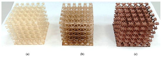
Figure 1.
Lattice structures: (a) lattice structure printed from modified resin; (b) lattice structure immersed in an activator solution; (c) lattice structure with a copper coating applied.
The continuity achieved during the chemical metallization of the composite material was examined using scanning electron microscopy method SEM (VEGA3 TESCAN electron microscope, Brno, Czech Republic).
The dielectric properties of the material were measured in accordance with GOST 22372-77 [52], using a Jinko JK2832 LCR universal tester (Changzhou Jinko Electronic Technology Co., Ltd., Changzhou, China) [53,54]. Measurements were performed on two sets of samples: one set comprised samples printed from pure commercial resin, and the other set consisted of resin modified with tannin.
The thickness of the material layers was measured using scanning electron microscopy. Modern, high-precision, versatile thickness gauges, such as the PCE-CT 27FN (PCE Group, Meschede, Germany) and PCE-CT 100 (PCE Group, Meschede, Germany), were also used to measure the thickness of the surface layers.
Film resistance was measured using a two-configuration four-point probe method in accordance with ASTM F1529-02 on three samples.
The measured current and voltage values were used in calculations according to the following Formulas (1)–(4) [54]:
- -
- for values obtained using the connection diagram A:
- -
- for the values obtained using the connection diagram B:
where Vf and Vr are the forward and reverse voltages;
If and Ir are the current values.
- -
- the coefficient Ka is calculated using the empirical formula:
- -
- surface resistance was calculated using the formula:
To test the adhesion of copper layers to a polymer substrate, qualitative methods (quick, visual, and requiring no sophisticated equipment) are used:
1. Scotch tape method (ASTM D3359). Adhesive tape is applied to the surface of the copper film, held in place for 30 s, and then quickly removed [55].
2. Grid Cut Method (ISO 2409). Using a Konstanta KN-1 knife (Konstanta-MSK LLC, Russia), a 5 × 5 grid of cuts is made with a pitch of 1–2 mm. Tape is applied over the cuts and then removed. Adhesion is assessed on a 6-point scale, ranging from 0 (no delamination) to 5 (complete delamination) [56].
3. Results and Discussion
Given the tendency of tannins to coagulate in concentrated solutions and at elevated temperatures, special measures were implemented to minimize thermal exposure during the printing process. Temperature conditions were maintained at the minimum permissible level (+18 °C) during both resin emulsification and printing, in accordance with the technical requirements for the resin used. If these conditions were not met, tannin coagulated. The coagulate could appear on the sample surface, creating zones with increased reducing capacity. This led to enhanced formation of silver deposition sites from the activator solution and subsequently more active copper deposition from the electrolyte. Consequently, the copper layer exhibited areas of loose coating.
During the formation of the polymer composite material, IR spectroscopy was employed to monitor the chemical interactions between the resin and the modifying additive (Figure 2). To optimize the functional and mechanical properties of the composite materials, we studied polymer samples printed from unmodified resin, modified resin, modified resin followed by curing in an AgNO3 solution, as well as a region with tannin coagulate exposed on the surface, which resulted in a darkened area. Based on the obtained spectra (Figure 2), we concluded that there is no significant chemical interaction between the modifying additive and the base resin; their interaction is limited to the distribution of the additive within the bulk, as is typical for a composite.
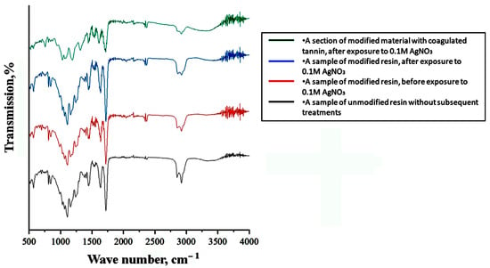
Figure 2.
IR spectra of unmodified and modified resin samples before and after exposure to the activator, including the area of local darkening.
Moreover, since the tannin is contained within the bulk of the product, it is not washed off the surface and does not cause damage to the AgNO3 solution. As it was suggested, the tannin film readily dissolves in an aqueous AgNO3 solution, triggering the release of atomic silver throughout the activator solution. Bulk-sensitized samples do not release tannin into the solution, and their shelf life exceeds 24 h when stored in a shaded area.
The degree of cross-linking in the polymer material can influence its ability to form deposition sites on the surface. To test this hypothesis, a series of samples were printed with varying layer exposure times of 9, 16, 23, 30, and 37 s. Shorter exposure times were not feasible due to delamination of the samples from the build platform. After printing, washing, and weighing on a VLTE-510T analytical balance (GOSMETR, Russia), the samples were soaked in 0.1 M AgNO3 for the same time. Following soaking, the samples were blotted to remove excess moisture and reweighed. This process is clearly reflected in the samples’ appearance, which acquires a characteristic color. The color intensity varies, as shown in Table 3.

Table 3.
Changes in the appearance of samples and mass during the experiment.
Copper was selected as the surface layer of the composite material because its electrical conductivity is second only to gold and silver, which are significantly more expensive. Additionally, copper offers excellent adhesion and conductivity for electroplated coatings of other metals, such as nickel and silver, making it widely used in the production of various instrumentation and electronic products. A polymer base was chosen as the functional substrate due to its low cost and advanced processing capabilities—it is easier to shape using various molding technologies. However, polymers are generally inferior to other materials in both mechanical and functional properties. Applying metallic surface layers imparts conductive and shielding properties to polymer products, providing protection against photodegradation and accelerated wear. Ultimately, metallized coatings enable the rapid and cost-effective manufacturing of products that would otherwise be very expensive or even impossible to produce using metals alone.
The results of a study on the structure of a polymer-copper composite material are presented in Figure 3. Macro- and microanalysis of the surface layers of the composites, produced using the established technology, revealed a sufficiently dense structure. The interface between the layers was free of visible defects (Figure 3d). The copper layer thickness ranged from 0.7 to 0.8 µm, which is optimal for the mechanical properties of the composites.
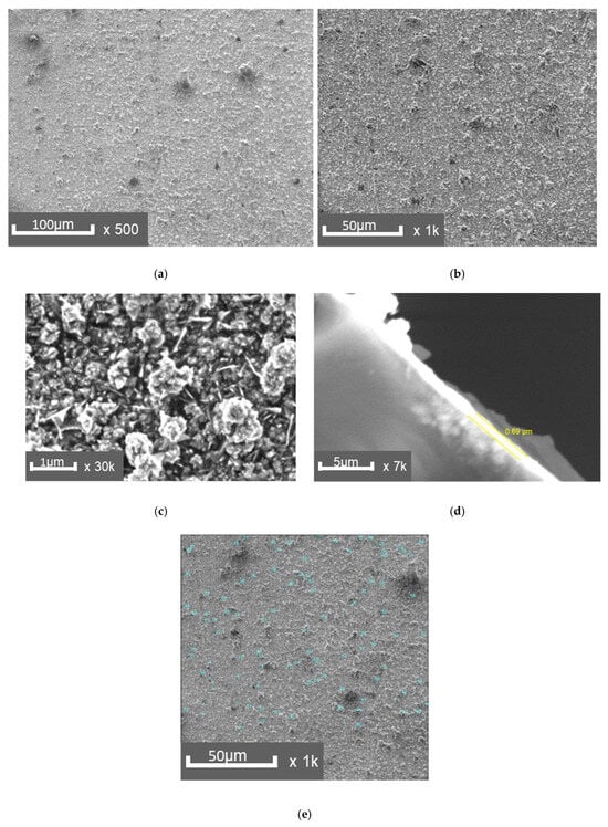
Figure 3.
SEM images of the copper layer surface: (a)—×500, (b)—×1000, (c)—×30,000, (d)—×7000, side section of the layer, (e)—measurement of defects on the copper layer.
A chemical analysis of the copper layer in the composite material was performed (Figure 4): Cu = 98%, C = 0.1%, O = 1.1%, P = 0.2%, Ag = 0.6%.
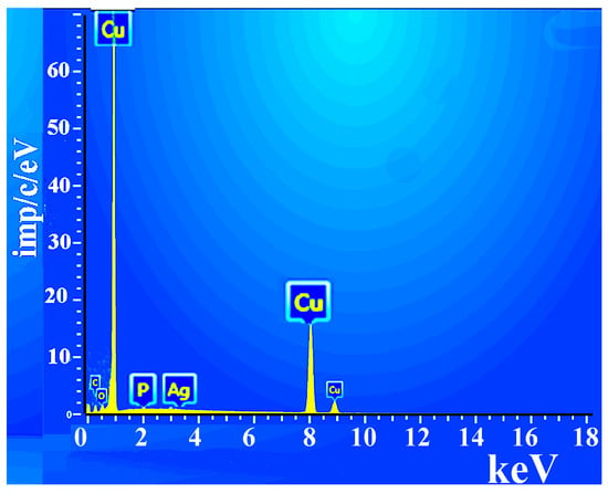
Figure 4.
Elemental analysis of the composite surface.
As a result of experimental and mathematical analysis using Statistica 10.0, a 3D model was constructed, and an empirical mathematical equation was developed to describe the effect of time and solution temperature on the surface layer thickness (δl) (Equation (5)). The surface layer thickness increases more rapidly as the solution temperature rises (Figure 5).
where Ts—temperature of the chemical metallization solution, °C; tp—process time, min.
δl = −111.8548 + 2.6313·Ts + 2.5637·tp − 0.015·Ts2 − 0.0302·Ts·tp − 0.0146 · tp2, (μm)
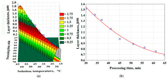
Figure 5.
The effect of time and temperature of the solution on the thickness of the surface layer of the composite—(a); the effect of saturation time on the thickness of the surface layer (Red line-average values of layer thickness; Blue dots are the values obtained as a result of the experiment)—(b).
3.1. Dielectric Properties of Materials
Dielectric parameter measurements showed that the modifying additive caused minor changes to the material’s properties. The loss tangent increased from 0.025794 (pure material) to 0.028595 (modified composition), indicating an 11.28% increase in dielectric loss. Simultaneously, the permittivity rose from 4.20371 to 4.31546 (a 2.62% increase), reflecting a change in the material’s polarization behavior. These results demonstrate that the modifying additive has a complex effect on the dielectric characteristics: it enhances permittivity while also increasing energy loss. Such changes may result from structural transformations in the material induced by the additive, which affect polarization mechanisms and relaxation processes within the dielectric.
3.2. Resistance Measurement
As shown in Figure 6, the layers formed in the Rochelle salt-based electrolyte exhibit a characteristic copper color. The coating is uneven, featuring shiny areas alongside redeposition zones with a looser, matte appearance. In contrast, the sample produced using the trilonate complex-based electrolyte lacks the rich red color, but has a smoother and glossier coating.
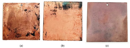
Figure 6.
Appearance of copper-plated samples obtained in an electrolyte based on Rochelle salt (a,b) and in an electrolyte based on Trilon (c).
Our studies revealed significant differences in the properties of copper layers deposited from a homemade Rochelle salt-based electrolyte compared to those from a commercial Trilon electrolyte. Although the coating from our electrolyte was non-continuous, exhibiting bald spots and a reddish-copper color, the films demonstrated superior conductivity (0.056 and 0.024 Ω/□) relative to the Trilon electrolyte sample (0.091 Ω/□), which produced a continuous, glossy, but lighter-colored coating.
This paradox—the superior conductivity of a coating with less perfect morphology—can be explained by several factors. First, the composite layers obtained from the electrolyte likely have a coarser crystalline structure with fewer grain boundaries, which are the primary centers of electron scattering. Second, the commercial electrolyte likely contains nickel additives to improve adhesion, resulting in increased resistivity. Third, organic components in the commercial electrolyte (if present) could leave impurities in the film, creating additional barriers to charge movement.
Thus, the visual continuity of a composite layer does not always correlate with its electrical properties. In this case, local defects in the composite layer may be compensated for by the high purity of the copper phase and the favorable crystal orientation of the layer obtained from the electrolyte.
As a result of mathematical processing of the data obtained during the experiment, a 3D model was constructed (Figure 7a). Moreover, empirical mathematical equations were developed to describe the effects of time and solution temperature on the surface layer resistance (Rs, Ω/□) (Equation (6)). The surface layer resistance increases more rapidly with rising solution temperature (Figure 7a). Additionally, as the surface layer thickness increases, the specific surface resistance also increases (Figure 7b) (Equation (7)). This parameter measures the electrical resistance of thin layers and conductors, independent of their area.
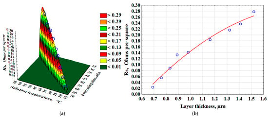
Figure 7.
The effect of time and temperature of the solution on the resistance of the surface layer of the composite—(a); the effect of the thickness of the surface layer on the resistance value—(b).
The resistance of the surface layer (Rs, Ω/□) is described by the following equations:
where Ts—temperature of the chemical metallization solution, °C; tp—process time, min; δl—surface layer thickness, µm.
Rs = −35.1116 + 0.7575·Ts + 0.8595·tp − 0.004·Ts2 − 0.0092·Ts · tp − 0.0053 · tp2, (Ω/□)
Rs = −0.3226 + 0.6242 · δl − 0.1567 · δl2, (Ω/□)
By developing a 3D printing technology for polymer materials and evaluating the impact of key process parameters on electrophysical properties and layer thickness, we plotted the relationships between relative permittivity and polymer layer thickness as functions of layer exposure time (Figure 8). Layer exposure time refers to the time during which ultraviolet light illuminates the resin in the printer vat to cure and form a single layer of the printed model. The figure demonstrates that incorporating tannin into the polymer matrix increases the relative permittivity.
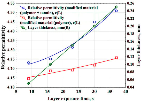
Figure 8.
Dependences of the relative permittivity and thickness of the polymer layer on the exposure time of the layer.
As a result of statistical processing of the experimental data, the relative permittivity (ε), layer exposure time (Et), and the thickness of the polymer layer (δlp) are related by the following mathematical relationships:
- -
- relative permittivity (tannin + polymer)
ε = 4.2008 + 0.0004 · Et +0.0002 · Et2
- -
- relative permittivity (polymer)
ε = 4.129 + 0.0025 · Et + 2.4536 · 10−5 · Et2
- -
- thickness of the polymer layer
δl p = −0.0143 + 0.0071 · Et (mm)
3.3. Evaluation of the Adhesion Strength of the Surface Layer of a Composite Material
Tests of copper layers on a polymer substrate composite material demonstrated that all samples exhibited excellent surface layer durability (Figure 9). No delamination of the surface layer was observed after applying cross-hatch notches and subsequent testing, indicating a high adhesion class (0–1 according to ISO 2409 or 5B according to ASTM D3359).
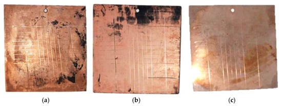
Figure 9.
Appearance of samples after making lattice cuts with the Constant KN-1 adhesion tester knife—(a–c).
Therefore, all samples meet the standard requirements, confirming the reliability of the surface layer under operating conditions.
The adhesive strength of the metallic copper layer ranged from 2.1 to 2.3 MPa. Statistical analysis of the experimental data enabled the construction of graphical dependencies illustrating the effect of surface layer thickness on adhesion (Figure 10a) and the derivation of mathematical equations describing the influence of surface layer thickness (δl) and key process parameters (Ts, tp) on adhesion (Equations (11) and (12)) (Figure 10b).
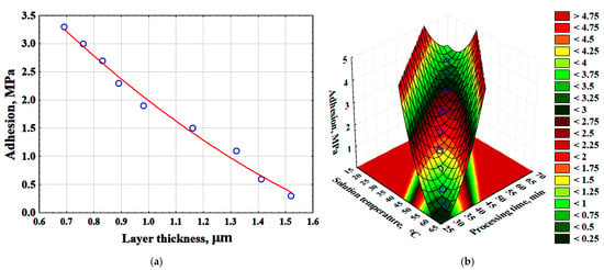
Figure 10.
Effect of surface-modified layer thickness on adhesion (red line-average values of adhesion; blue dots are the values obtained as a result of the experiment)—(a); effect of time and temperature of the solution on adhesion—(b).
The adhesive strength of surface layers in functionally graded materials is described by the following equations:
where Ts—temperature of the chemical metallization solution, °C; tp—process time, min; δl—surface layer thickness, µm.
Sa = 6.9263 − 6.1407 · δl + 1.2009 · δl2 (MPa)
Sa = 72.6531 − 1.6225 · Ts − 1.6046 · tp + 0.0087 · Ts2 + 0.0186 · Ts · tp + 0.0094 · tp2 (MPa)
4. Conclusions
Technology has been developed for creating composite materials with a gradient distribution of properties, combining a polymer material (produced using SLA printing) with layers of conductive metal (applied using chemical metallization). These composites exhibit increased strength (compared to pure polymer), surface layer electrical conductivity, and increased durability, enabling the achievement of the required functional and mechanical characteristics.
As a result of technological advancements, optimal process parameters for the formation of graded materials were determined. To demonstrate the influence of key process parameters on the functional and mechanical properties of the composites, three-dimensional models were constructed and mathematical equations were developed. The influence of a modifying additive (tannin) on the dielectric characteristics of the polymer substrate was described: on one hand, the additive increases permittivity; on the other, it leads to an increase in energy loss. These changes may result from structural transformations in the material induced by the additive, which affect polarization mechanisms and relaxation processes in the dielectric. A correlation was established between the layer exposure settings and the efficiency of deposition center formation. Samples exposed for longer periods during printing exhibited lower recovery capacity, whereas samples with shorter exposure times showed more active silver deposition. This phenomenon can be exploited to selectively deposit a layer on areas printed with shorter exposure times.
SEM analysis revealed that chemical vapor deposition produces a nanocrystalline copper coating with grain sizes predominantly up to 100 nm. The morphology of the surface layer reflects controlled deposition conditions and influences its functional properties, including specific surface area and adhesion characteristics.
The electrolyte composition influenced the quality of the copper film. An electrolyte based on trilon complexes ensured better adhesion of the coating to the substrate, higher gloss, and more stable deposition compared to a Rochelle salt-based electrolyte. However, surface resistance measurements indicated that the samples prepared with the Rochelle salt-based electrolyte exhibited higher conductivity.
To determine the properties of surface conductive layers produced by the chemical metallization method, the following analyses were performed: the continuity and thickness of the copper surface layer were studied (which was found to be 0.7–0.8 μm); the dielectric properties of the polymer material were measured (relative permittivity was ε = 4.2–4.3); the resistance of the copper surface layer was measured at 0.021–0.278 Ohm/sq; and adhesion tests were conducted on the surface layer.
The obtained surface resistance values suggest that the formation of surface metal layers in functionally graded materials, using the proposed technology, can be used to create conductive structures in the electronics industry.
Author Contributions
Conceptualization, P.R.; Methodology, S.T., V.K. and P.R.; Software, V.K.; Validation, S.T., V.K. and P.R.; Formal analysis, S.T., V.K. and V.D.; Investigation, V.K. and V.D.; Resources, V.D.; Data curation, V.K. and V.D.; Writing—original draft, P.R.; Writing—Review And Editing, S.T., C.Z. and P.R.; Supervision, S.T.; Project administration, S.T. and V.D. All authors have read and agreed to the published version of the manuscript.
Funding
This study was conducted as part of the project “Development of a Technology for the Production of New-Generation Nanostructured Composite Materials with Low Volume Electrical Resistivity and Functional Coatings” to achieve the results of the federal project “Universities for a Generation of Leaders” of the national project “Youth and Children,” with the support of the Ministry of Science and Higher Education of the Russian Federation.
Institutional Review Board Statement
Not applicable.
Data Availability Statement
The original contributions presented in this study are included in the article. Further inquiries can be directed to the corresponding author.
Conflicts of Interest
The authors declare no conflicts of interest.
References
- Yadav, S.; Liu, S.; Singh, R.K.; Sharma, A.K.; Rawat, P. A state-of-art review on functionally graded materials (FGMs) manufactured by 3D printing techniques: Advantages, existing challenges, and future scope. J. Manuf. Process. 2024, 131, 2051–2072. [Google Scholar] [CrossRef]
- Van Doan, D.; Van Minh, P.; Van Ke, T.; Nhung, N.T.C.; Van Thom, D. An Overview of Functionally Graded Materials: From Civil Applications to Defense and Aerospace Industries. J. Vib. Eng. Technol. 2025, 13, 68. [Google Scholar] [CrossRef]
- Silva, R.F.; Coelho, P.G.; Gustavo, C.V.; Almeida, C.J.; Farias, F.W.C.; Duarte, V.R.; Xavier, J.; Esteves, M.B.; Conde, F.M.; Cunha, F.G.; et al. Functionally Graded Materials and Structures: Unified Approach by Optimal Design, Metal Additive Manufacturing, and Image-Based Characterization. Materials 2024, 17, 4545. [Google Scholar] [CrossRef]
- Li, K.; Zhang, M.; Zhang, Z.; Jin, P.; Wang, Y.; Yan, W.; Zhu, L.; Zhang, D.Z.; Murr, L.E. High performance realization of functionally graded materials based on integrated optimal design and additive manufacturing: A review. Int. Mater. Rev. 2025, 70, 497–547. [Google Scholar] [CrossRef]
- Bazyar, M.M.; Tabary, S.B.; Rahmatabdi, D.; Mohammadi, K.; Hashemi, R. A novel practical method for the production of Functionally Graded Materials by varying exposure time via photo-curing 3D printing. J. Manuf. Process. 2023, 103, 136–143. [Google Scholar] [CrossRef]
- Lin, Q. Polymeric electronic materials for microelectronics manufacturing: A review. Polymer 2023, 286, 126395. [Google Scholar] [CrossRef]
- Liang, R.; Sun, Y.; Zhu, J. Applications of Polymer Materials in Power Industry, Tissue Engineering and Fuel Cells. Highlights Sci. Eng. Technol. 2022, 13, 190–197. [Google Scholar] [CrossRef]
- Rambabu, K.; Gandhi, P.; Susmitha, M.; Sravanthi, K. A review on different techniques to produce gradient structured material. Mater. Today Proc. 2022, 60, 2262–2265. [Google Scholar] [CrossRef]
- Askadskii, A.A.; Goleneva, L.M.; Afanas’ ev, E.S.; Petunova, M.D. Gradient polymeric materials. Rev. J. Chem. 2012, 2, 105–152. [Google Scholar] [CrossRef]
- Bronstein, L.M.; Ivanovskaya, A.; Mates, T.; Holten-Andersen, N.; Stucky, G.D. Bioinspired gradient materials via blending of polymer electrolytes and applying electric forces. J. Phys. Chem. B 2009, 113, 647–655. [Google Scholar] [CrossRef]
- Zhang, Y.; Liu, Y.; Ren, G.; Yu, C. High-throughput printing of functionally gradient material from self-propagation. Nat. Commun. 2025, 16, 9706. [Google Scholar] [CrossRef] [PubMed]
- Dhinesh, S.K.; Robert, J.J.; Nair, S.T.; Moni, D.H.S.; Fowzeya, S.S.; Kumar, K.L.S.; Raghunath, M.; Nagarajan, P. Recent trends in additive manufacturing of electronics devices. Mater. Today Proceeding 2022, 66, 928–941. [Google Scholar] [CrossRef]
- Chen, J.; Yue, Y.; Qianshu, W.; Hanyu, W.; Rigoberto, C.A. Bridging Additive Manufacturing and Electronics Printing in the Age of AI. Nanomaterials 2025, 15, 843. [Google Scholar] [CrossRef]
- Zikulnig, J.; Chang, S.; Bito, J.; Rauter, L.; Roshanghias, A.; Carrara, S.; Kosel, J. Printed Electronics Technologies for Additive Manufacturing of Hybrid Electronic Sensor Systems. Adv. Sens. Res. 2023, 2, 2200073. [Google Scholar] [CrossRef]
- Lopez, A.G.; Chandra, R.; Johansson, A.J. Optimization and fabrication by 3D printing of a volcano smoke antenna for UWB applications. In Proceedings of the 2013 7th European Conference on Antennas and Propagation (EuCAP), Gothenburg, Sweden, 8–12 April 2013; p. 2013. [Google Scholar]
- Jian, J.R.; Kim, T.; Park, J.S.; Wang, J.; Kim, W.S. High performance 3D printed electronics using electroless plated copper. AIP Adv. 2017, 7, 035314. [Google Scholar] [CrossRef]
- Hong, Z.; Zhang, Z.; You, R.; Chen, J.; Li, S.; Wang, Y.; Sun, Y.; Song, B.; Ji, Z.; Loy, D.A.; et al. Dual-head multi-photon polymerization 3D printing for parallel additive manufacturing organic/inorganic materials in optics. Addit. Manuf. 2025, 103, 104772. [Google Scholar] [CrossRef]
- Vorunichev, D.S.; Kostin, M.S. Investigation of the profilogram structure of microstrip microwave modules manufactured using additive 3D-printing technology. Russ. Technol. J. 2023, 11, 34–44. [Google Scholar] [CrossRef]
- Ivanov, V.S.; Gladky, D.A.; Vorunichev, D.S. LPKF-LDS technology for the production of three-dimensional schemes on plastics. Russ. Technol. J. 2021, 9, 48–57. (In Russia) [Google Scholar] [CrossRef]
- Reis, J.P.; de Moura, M.; Samborski, S. Thermoplastic Composites and Their Promising Applications in Joining and Repair Composites Structures: A Review. Materials 2020, 13, 5832. [Google Scholar] [CrossRef]
- Romani, A.; Mantelli, A.; Tralli, P.; Turri, S.; Levi, M.; Suriano, R. Metallization of Thermoplastic Polymers and Composites 3D Printed by Fused Filament Fabrication. Technologies 2021, 9, 49. [Google Scholar] [CrossRef]
- Perna, A.S.; Auriemma Citarella, A.; De Marco, F.; Di Biasi, L.; Viscusi, A.; Tortora, G.; Durante, M. Optimizing Cold Spray Deposition on Thermoplastics: A Machine Learning Approach Focused on Powder Properties. J. Mater. Eng. Perform. 2025, 34, 6527–6538. [Google Scholar] [CrossRef]
- Sarac, E.C.; Poudeh, L.H.; Zanjani, J.S.M.; Cebeci, F.Ç.; Aydin, I.; Menceloglu, Y.; Okan, B.S. New hybrid nano additives for thermoplastic compounding: CVD grown carbon fiber on graphene. AIP Conf. Proc. 2020, 2205, 020067. [Google Scholar] [CrossRef]
- Muraliraja, R.; Selvan, R.A.S.; Selvakumar, A.; Franco, M.; Tamilarasan, T.R.; Sanjith, U.; Sha, W.; Sudagar, J. A review of electroless coatings on non-metals: Bath conditions, properties and applications. J. Alloys Compd. 2023, 960, 170723. [Google Scholar] [CrossRef]
- Sun, L.; Yuan, G.; Gao, L.; Yang, J.; Chhowalla, M.; Gharahcheshmeh, M.H.; Gleason, K.K.; Choi, Y.S.; Hong, B.H.; Liu, Z. Chemical vapour deposition. Nat. Rev. Methods Primers 2021, 1, 5. [Google Scholar] [CrossRef]
- Sabzi, M.; Mousavi Anijdan, S.H.; Shamsodin, M.; Farzam, M.; Hojjati-Najafabadi, A.; Feng, P.; Park, N.; Lee, U. A Review on Sustainable Manufacturing of Ceramic-Based Thin Films by Chemical Vapor Deposition (CVD): Reactions Kinetics and the Deposition Mechanisms. Coatings 2023, 13, 188. [Google Scholar] [CrossRef]
- Heydari Gharahcheshmeh, M. Fabrication of Conjugated Conducting Polymers by Chemical Vapor Deposition (CVD) Method. Nanomaterials 2025, 15, 452. [Google Scholar] [CrossRef] [PubMed]
- Jaitpal, S.; Chavva, S.R.; Mabbott, S. 3D Printed SERS-Active Thin-Film Substrates Used to Quantify Levels of the Genotoxic Isothiazolinone. ACS Omega 2022, 7, 2850–2860. [Google Scholar] [CrossRef] [PubMed]
- Melentiev, R.; Yudhanto, A.; Tao, R.; Vuchkov, T.; Lubineau, G. Metallization of polymers and composites: State-of-the-art approaches. Mater. Des. 2022, 221, 110958. [Google Scholar] [CrossRef]
- Tengsuthiwat, J.; Sanjay, M.R.; Siengchin, S.; Pruncu, C.I. 3D-MID Technology for Surface Modification of Polymer-Based Composites: A Comprehensive Review. Polymers 2020, 12, 1408. [Google Scholar] [CrossRef]
- Camargo, M.K.; Uebel, M.; Kurniawan, M.; Ziegler, K.F.; Seiler, M.; Grieseler, R.; Schmidt, U.; Barz, A.; Bliedtner, J.; Bund, A. Selective Metallization of Polymers: Surface Activation of Polybutylene Terephthalate (PBT) Assisted by Picosecond Laser Pulses. Adv. Eng. Mater. 2022, 24, 2100933. [Google Scholar] [CrossRef]
- Seiler, M.; Knauft, A.; Gruben, J.J.; Frank, S.; Barz, A.; Bliedtner, J.; Lasagni, A.F. Modification of Polymeric Surfaces with Ultrashort Laser Pulses for the Selective Deposition of Homogeneous Metallic Conductive Layers. Materials 2022, 15, 6572. [Google Scholar] [CrossRef]
- Nassajfar, M.N.; Deviatkin, I.; Leminen, V.; Horttanainen, M. Alternative Materials for Printed Circuit Board Production: An Environmental Perspective. Sustainability 2021, 13, 12126. [Google Scholar] [CrossRef]
- Zdráhal, J.; Reinšteinová, L.; Koc, D.; Uřičář, J.; Dušek, K.; Veselý, P. 3D Printed Circuit Boards from Recycled Plastics: Conductive Pattern Properties. In Proceedings of the 2025 International Spring Seminar on Electronics Technology (ISSE), Budapest, Hungary, 14–18 May 2025; pp. 1–7. [Google Scholar] [CrossRef]
- Fazlali, Z.; Schaubroeck, D.; Cauwe, M.; Cardon, L.; Bauwens, P.; Vanfleteren, J. Polylactic Acid and Polyhydroxybutyrate as Printed Circuit Board Substrates: A Novel Approach. Processes 2025, 13, 1360. [Google Scholar] [CrossRef]
- Honarbari, A.; Cataldi, P.; Zych, A.; Merino, D.; Paknezhad, N.; Ceseracciu, L.; Perotto, G.; Crepaldi, M.; Athanassiou, A. A Green Conformable Thermoformed Printed Circuit Board Sourced from Renewable Materials. ACS Appl. Electron. 2023, 5, 4690–5257. [Google Scholar] [CrossRef]
- Zhan, J.; Tamura, T.; Li, X.; Ma, Z.; Sone, M.; Yoshino, M.; Umezu, S.; Sato, H. Metal-plastic hybrid 3D printing using catalyst-loaded filament and electroless plating. Addit. Manuf. 2020, 36, 101556. [Google Scholar] [CrossRef]
- Díaz-Marta, A.S.; Tubío, C.R.; Carbajales, C.; Fernández, C.; Escalante, L.; Sotelo, E.; Guitián, F.; Barrio, V.L.; Gil, A.; Coelho, A. Three-Dimensional Printing in Catalysis: Combining 3D Heterogeneous Copper and Palladium Catalysts for Multicatalytic Multicomponent Reactions. ACS Catal. 2018, 8, 392–404. [Google Scholar] [CrossRef]
- Zeb, G.; Duong, X.T.; Vu, N.P.; Phan, Q.T.; Nguyen, D.T.; Ly, V.A.; Salimy, S.; Le, X.T. Chemical metallization of KMPR photoresist polymer in aqueous solutions. Appl. Surf. Sci. 2017, 407, 518–525. [Google Scholar] [CrossRef]
- Li, R.; Gao, Y.; Wang, J.; Xu, H.; Zhang, Z.; Wang, M.; Wang, H. A sustainable and palladium-free approach for ABS surface metallization using low-temperature plasma technology. Appl. Surf. Sci. 2025, 690, 162611. [Google Scholar] [CrossRef]
- Li, L.; Ma, Y.; Xie, J.; Yang, X.; Wang, H.; Tian, H.; Mu, H.; Wang, W. Metallization Process of a Polyimide Surface with Palladium-Free Activation for Electronic Field Applications. J. Electron. Mater. 2015, 44, 4042–4051. [Google Scholar] [CrossRef]
- De Leeuw, D.M.; Kraakman, P.A.; Bongaerts, P.F.G.; Mutsaers, C.M.J.; Klaassen, D.B.M. Electroplating of conductive polymers for the metallization of insulators. Synth. Met. 1994, 66, 263–273. [Google Scholar] [CrossRef]
- Augustyn, P.; Rytlewski, P.; Moraczewski, K.; Mazurkiewicz, A. A review on the direct electroplating of polymeric materials. J. Mater. Sci. 2021, 56, 14881–14899. [Google Scholar] [CrossRef]
- Stier, S.P.; Böse, H. Electroplating and Ablative Laser Structuring of Elastomer Composites for Stretchable Multi-Layer and Multi-Material Electronic and Sensor Systems. Micromachines 2021, 12, 255. [Google Scholar] [CrossRef]
- Su, X.; Li, X.; Ong, C.Y.A.; Herng, T.S.; Wang, Y.; Peng, E.; Ding, J. Metallization of 3D Printed Polymers and Their Application as a Fully Functional Water-Splitting System. Adv. Sci. 2019, 6, 1801670. [Google Scholar] [CrossRef]
- Perera, A.T.K.; Song, K.; Umezu, S.; Sato, H. Recent progress in functionalized plastic 3D printing in creation of metallized architectures. Mater. Des. 2023, 232, 112044. [Google Scholar] [CrossRef]
- Perna, A.S.; Viscusi, A.; Gatta, R.D.; Astarita, A. Integrating 3D printing of polymer matrix composites and metal additive layer manufacturing: Surface metallization of 3D printed composite panels through cold spray deposition of aluminium particles. Int. J. Mater. Form. 2022, 15, 15. [Google Scholar] [CrossRef]
- Liu, T.L.; Bent, S.F. Nanostructure fabrication by area selective deposition: A brief review. Mater. Horiz. 2025, 12, 1711–1725. [Google Scholar] [CrossRef] [PubMed]
- Kucherov, F.A.; Romashov, L.V.; Ananikov, V.P. Development of 3D+G printing for the design of customizable flow reactors. Chem. Eng. J. 2022, 430, 132670. [Google Scholar] [CrossRef]
- Levy, A.; Toker, G.B.; Chan, D.J.L.; Ermak, O.; Peled, I.; Atar, N.; Gouzman, I.; Zenou, M.; Kotler, Z.; Gelbstein, Y. Hybrid structural electronics fabrication by combined SLA and metal printing. Smart Mater. Struct. 2023, 32, 065003. [Google Scholar] [CrossRef]
- Rao, C.H.; Avinash, K.; Varaprasad, B.K.S.V.L.; Goel, S. A Review on Printed Electronics with Digital 3D Printing: Fabrication Techniques, Materials, Challenges and Future Opportunities. J. Electron. Mater. 2022, 51, 2747–2765. [Google Scholar] [CrossRef]
- Zhang, N.; Wang, Z.; Zhao, Z.; Zhang, D.; Feng, J.; Yu, L.; Lin, Z.; Guo, Q.; Huang, J.; Mao, J.; et al. 3D printing of micro-nano devices and their applications. Microsyst. Nanoeng. 2025, 11, 35. [Google Scholar] [CrossRef] [PubMed]
- GOST 22372-77; Dielectric Materials. Methods for Determining Permittivity and Dielectric Loss Tangent in the Frequency Range from 100 to 5-106 Hz. State Committee of the USSR for Standards: Moscow, Russia, 1977.
- Kharalgin, S.V.; Voytovich, M.I. Investigation of the dielectric characteristics of materials manufactured using additive technologies. Russ. Technol. J. 2021, 9, 57–65. (In Russia) [Google Scholar] [CrossRef]
- ASTM 1529-02; Standard Test Method for Sheet Resistance Uniformity Evaluation by In-Line Four-Point Probe with the Dual-Configuration Procedure. ASTM International: West Conshohocken, PA, USA, 2002. [CrossRef]
- ASTM D3359; Standard Test Methods for Adhesion by Tape Test. ASTM International: West Conshohocken, PA, USA, 2023.
Disclaimer/Publisher’s Note: The statements, opinions and data contained in all publications are solely those of the individual author(s) and contributor(s) and not of MDPI and/or the editor(s). MDPI and/or the editor(s) disclaim responsibility for any injury to people or property resulting from any ideas, methods, instructions or products referred to in the content. |
© 2025 by the authors. Licensee MDPI, Basel, Switzerland. This article is an open access article distributed under the terms and conditions of the Creative Commons Attribution (CC BY) license (https://creativecommons.org/licenses/by/4.0/).


