Article

A Novel Triple Crosslinking Strategy on Carbon Nanofiber Membranes as Flexible Electrodes for Lithium-Ion Batteries

1
Institute of Photovoltaics, Nanchang University, Nanchang 330031, China
2
Guangxi Key Laboratory of Information Materials, Guilin University of Electronic Technology, Guilin 541004, China
*
Authors to whom correspondence should be addressed.
Polymers 2022, 14(17), 3528; https://doi.org/10.3390/polym14173528
Submission received: 2 August 2022 / Revised: 24 August 2022 / Accepted: 25 August 2022 / Published: 28 August 2022
(This article belongs to the Special Issue Advanced Electrospinning Fibers)

Abstract

:
In order to solve the problem of low electrical conductivity of carbon nanofiber membranes, a novel triple crosslinking strategy, including pre-rolling, solvent and chemical imidization crosslinking, was proposed to prepare carbon nanofiber membranes with a chemical crosslinking structure (CNMs-CC) derived from electrospinning polyimide nanofiber membranes. The physical-chemical characteristics of CNMs-CC as freestanding anodes for lithium-ion batteries were investigated in detail, along with carbon nanofiber membranes without a crosslinking structure (CNMs) and carbon nanofiber membranes with a physical crosslinking structure (CNMs-PC) as references. Further investigation demonstrates that CNMs-CC exhibits excellent rate performance and long cycle stability, compared with CNMs and CNMs-PC. At 50 mA g−1, CNMs-CC delivers a reversible specific capacity of 495 mAh g1. In particular, the specific capacity of CNMs-CC is still as high as 290.87 mAh g−1 and maintains 201.38 mAh g−1 after 1000 cycles at a high current density of 1 A g−1. The excellent electrochemical performance of the CNMs-CC is attributed to the unique crosslinking structure derived from the novel triple crosslinking strategy, which imparts fast electron transfer and ion diffusion kinetics, as well as a stable structure that withstands repeated impacts of ions during charging and discharging process. Therefore, CNMs-CC shows great potential to be the freestanding electrodes applied in the field of flexible lithium-ion batteries and supercapacitors owing to the optimized structure strategy and improved properties.

1. Introduction

Energy storage technologies have embraced a golden period of development in recent decades as energy demand increases [1,2]. Carbon fiber, an interesting candidate among carbon-based anode materials, has attracted great popularity owing to a series of characteristics such as a high elastic modulus, excellent electrical conductivity, chemical stability and rich sources, which has been extensively researched as an electrode material for flexible lithium-ion batteries (LIBs) [3], lithium-metal batteries [4], lithium-sulfur batteries [5] and supercapacitors [6]. Flexible electrodes are the core component of flexible energy storage devices [7]. Metals with excellent electrical and mechanical properties have been widely employed as current collectors for various electrodes. Generally, active powder materials, conductive additives, and binders have to be coated on the rigid metal foil in the traditional electrode preparation technology. However, the shortcomings of poor mechanical strength and easy detachment from the matrix will result in irreversible deformation during the bending process, which cannot meet the flexibility requirements [8,9]. Moreover, the volume energy density of the electrode is always reduced because of carbon black used as conductive additives and some polymers used as binders in the practical applications [10,11]. Therefore, the development of freestanding flexible electrodes without a binder and a current collector has been a promising strategy for flexible LIBs [12].
Electrospinning is a versatile, simple, and inexpensive fiber manufacturing process that has a very broad potential for energy storage [13,14,15]. The principle is to prepare non-woven products with fiber diameters ranging from the submicron to nanometer scale by using high-voltage electrostatic field forces as a traction force. Electrospinning nanofibers possess many excellent properties, such as porosity, flexibility, high fiber homogeneity, high specific surface area, mild preparation conditions, wide applicability, simple process, and excellent 3D pore structure [16]. Recently, with the maturity of electrospinning technology and abundance of spinnable raw materials, its development in the preparation of flexible anode has greatly expanded the choice of new materials for the anodes of LIBs. Carbon nanofiber membranes prepared by electrospinning exhibit excellent thermal stability, chemical stability, good electrical conductivity, mechanical properties and electrochemical properties, which can shorten diffusion paths of lithium ions and expand the specific surface area of electrode materials [17,18,19]. Electrospinning porous carbon nanofibers with a self-supporting structure do not require a current collector, a conductive agent and a binder when they are directly used as anodes, which can improve the energy density of anodes and simplify preparation process to save cost of production. Compared with slurry coating technology, flexible self-supporting carbon fibers electrodes have bright prospect and enormous challenges [20].
There are many precursors for the preparation of carbon fibers by electrospinning, mainly polyacrylonitrile (PAN) [21,22,23] and polyimide (PI) [24]. PI, a general term for a class of polymers containing imide rings in their main chains, is among the most comprehensive polymeric materials available [25]. Compared with PAN, PI has a higher carbon yield, better mechanical properties and electrochemical properties that have attracted the interest of a wide range of researchers [26]. Hence, CNM derived from PI becomes a new flexible anode for LIBs with great potential due to the benefits of high specific surface area of nanofiber membranes and thermal stability and chemical stability of PI [27].
To improve the electrochemical properties of carbon membranes, various strategies have been tried by many researchers, including N-doping strategies (ammonia [28], melamine [29], and urea [30]) and increasing the specific surface area of samples. Zhao et al. [31] prepared flexible heteroatoms-doped carbon nanofiber membranes with excellent rate and cycle performances, which showed a specific capacity of 695 mAh g−1 at 100 mA g−1 and a retain value of 245 mAh g−1 at 1.5 A g−1 after 300 cycles. Jiang et al. [32] reported an electrospun composite nanofiber obtained from polyacrylonitrile/zinc chloride as a precursor. The introduction of ZnCl2 can significantly enhance the specific surface area.
However, the preparation of crosslinking carbon nanofiber membranes and their effects on the comprehensive performance are still rarely studied. In particular, the electrochemical properties of anode are strongly correlated with their microscopic morphology, surface properties [33]. Typically, electrospun fibers are stacked to form a binder-free membrane. However, carbon fibers with high porosity usually exhibit physical contact, resulting in blocked electron transfer perpendicular to membranes. Hence, establishing a continuous electron transfer path can enhance the electronic conductivity of carbon membranes and thus improve energy storage properties.
In this work, a simple and novel triple crosslinking strategy of electrospinning CNMs-CC derived from PI was proposed to improve the electrical conductivity of samples used as flexible anode material for LIBs to a certain extent. Firstly, the physical contact of the fibers is made tight by pre-rolling, and then a strong chemical crosslinking structure is formed by the combined action of solvents and imidization reagents as shown in Figure 1. By the way, the effects of a crosslinking structure on the properties of samples were investigated by the characterization analysis of SEM, TG, DSC, XRD, etc. The results show that the introduction of the crosslinking structure effectively improves the loose lap problem and increases the interaction force of fibers. Therefore, the preparation of self-supporting CNMs electrodes with triple crosslinking structures may be confirmed to be a simple and practically applicable strategy for flexible LIBs.

2. Experimental

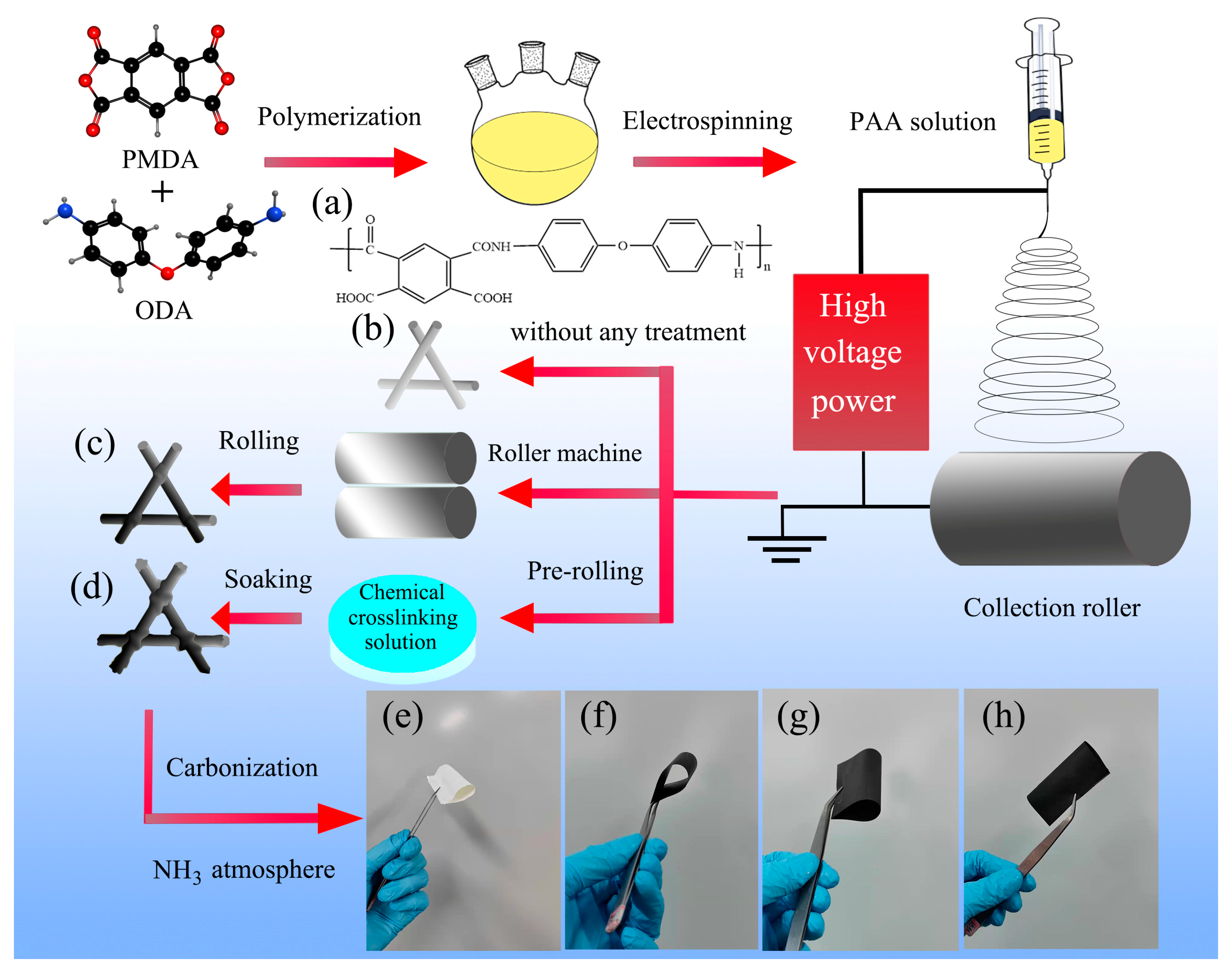
2.1. Preparation of Carbon Membranes

A two-step synthesis of polyimide was performed by condensation reaction of the pyromellitic dianhydride (PMDA, ≥99.5%) and the 4,4′-diaminodiphenyl ether (ODA, ≥99.5%) in a molar ratio of 1:1 to synthesize the precursor polyamide acid (PAA) solution. PMDA and ODA were supplied by Tianjin Haopu Chemical Co. Firstly, ODA was dissolved in 100 mL dimethylacetamide (DMAc) and stirred well under nitrogen. DMAc was purchased from Sinopharm Group Chemical Reagent Co. Next, PMDA was added to the solution in several portions for the polymerization reaction and mechanically stirred for 6 h. The total amount of solvent used was 135 g to form a ~10 wt% solution.
Then, the as-obtained PAA was placed in a 5 mL syringe as the spinning solution, and the PAA nanofiber membrane (PAANMs) was prepared by electrospinning technique. The precursor solution was pushed out by the syringe with the rate of 0.1 mm/min at the spinning voltage of 15 kV.
PAANMs were rolled by the electric roller press, and the thickness was reduced to approximately 50% of the original thickness to obtain physically crosslinking PAANMs (PAANMs-PC). The PAANMs and PAANMs-PC were imidized at 150 °C, 250 °C and 350 °C for 1 h, respectively, to obtain PINMs and PINMs-PC. The chemical reagents were obtained by mixing acetic anhydride, isoquinoline and DMAc with molar ratio of 1:0.5:0.1, where the acetic anhydride and the isoquinoline were acted as dehydrating agent and catalyst, respectively. Isoquinoline (97%) was provided by Shanghai Aladdin Biochemical Technology Co. (Shanghai, China). Acetic anhydride (AR) was provided Chengdu Kolon Chemical Co. (Chengdu, China) PAANMs-PCs were dipped into the above chemical reagents and kept at 60 °C, 70 °C and 80 °C for 10 min, and then imidized at the same conditions to obtain chemical crosslinking PINMs (PINMs-CC). Then, the three samples were carbonized at 700 °C for 0.5 h under argon, and activated by NH3 to obtain samples recorded as CNMs, CNMs-PC, and CNMs-CC, respectively.

2.2. Characterization

The morphologies of carbon membranes were observed by a scanning electron microscope (SEM, phenom pharos-type, Phenom-World, Eindhoven, Netherlands). Fourier-transform infrared spectroscopy was measured on a Nicolet iS50 infrared spectroscopy instrument (FT-IR, Nicolet iS50, Thermo fisher Scientific, MA, USA). Thermogravimetric analyzer (TGA, STA 2500, NETZSCH, Selb, Germany) was employed to analyze the pyrolysis behaviors of samples in flowing N2 at a heating rate of 10 °C/min from 30 to 800 °C. The tensile mechanical properties of samples (5 × 2 cm) were tested using an intelligent electronic tension machine (XLM, Labthink, Jinan, China) with a speed of 50 mm/min. The X-ray diffraction (XRD, D8 ADVANCE, Bruker, Karlsruhe, Germany) was performed by using Cu Kα radiation (λ = 0.154nm) with 2θ from 10 to 80 °. The Bruner-Emmet-Teller (BET) specific surface areas of the samples were obtained by the isothermal nitrogen adsorption and desorption measurements on a surface analyzer (TriStar II 3020, Micromeritics, Atlanta, USA). The electric conductivity was tested by a four-point probes resistivity tester (HPS2662, Changzhou, China). Contact angle measuring instrument (WAM-100, Shenzhen, China) was employed to identify the wettability. The variations of element state in the electrodes before and after NH3 treatment were investigated using X-ray photoelectron energy spectra (XPS, ESCALAB 250Xi, Thermo Fisher Scientific, MA, USA).

2.3. Electrochemical Measurement

The as-prepared CNMs, CNMs-PC and CNMs-CC (a diameter of 14 mm) were used as work electrodes without any binders to assemble CR2025-type coin cells with 1 M LiPF6/EC: DMC electrolyte in an argon-filled glovebox. Counter electrode was Li foil (15.6 × 0.45 mm). Celgard 2400 polypropylene film was used as separator. The amount of electrolyte added was 100 µL. Electrochemical performance was performed on Neware Battery Test System (Neware CT-4000, Shenzhen, China). Cyclic voltammetry (CV) tests with a rate of 0.1 mV s−1 between 0.01 and 1.5 V and electrochemical impedance spectroscopy (EIS) tests in the frequency range from 100 kHz to 0.1 Hz were performed on Princeton Applied Research Spectrometer (Versa STAT 3, DE, USA).

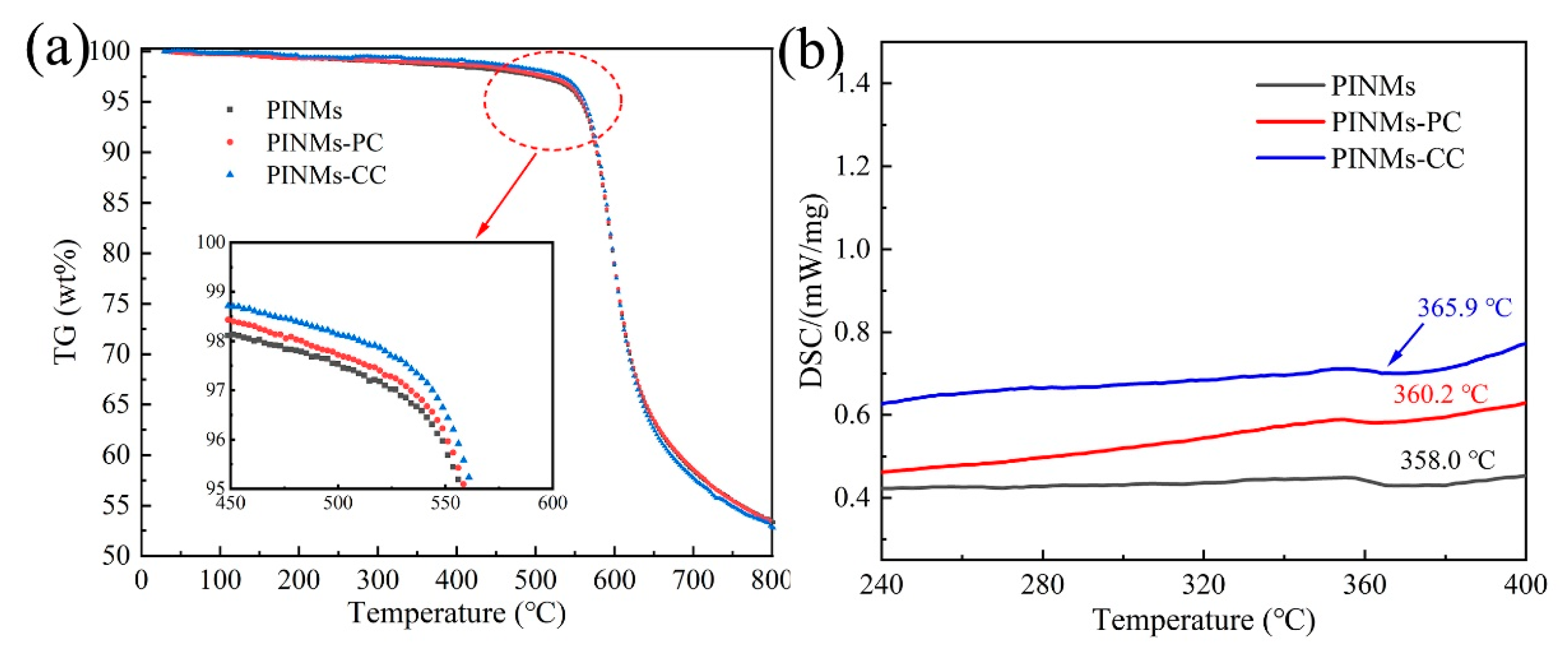
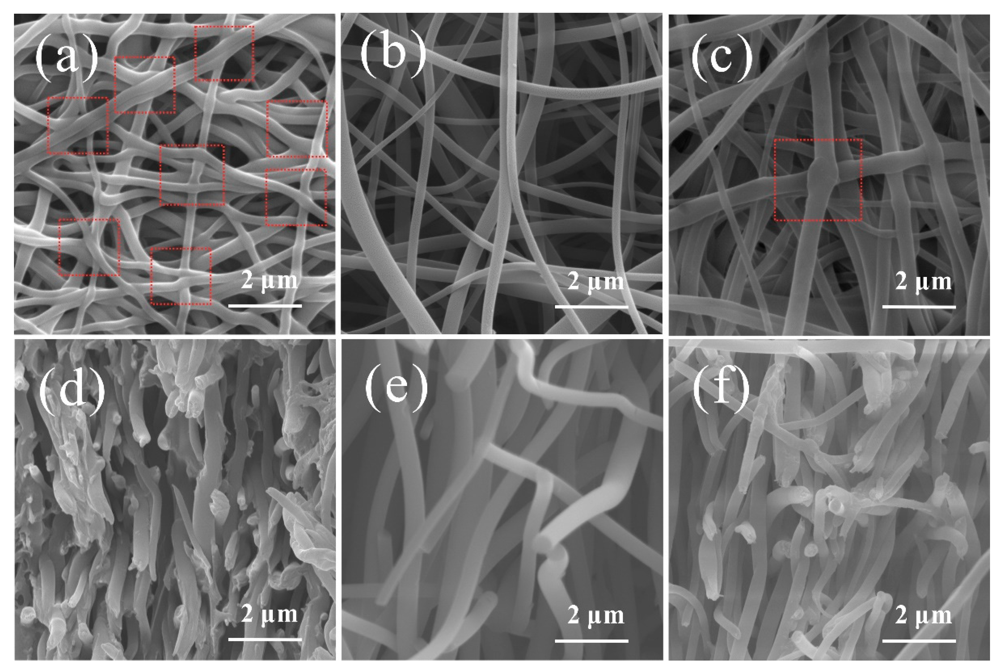
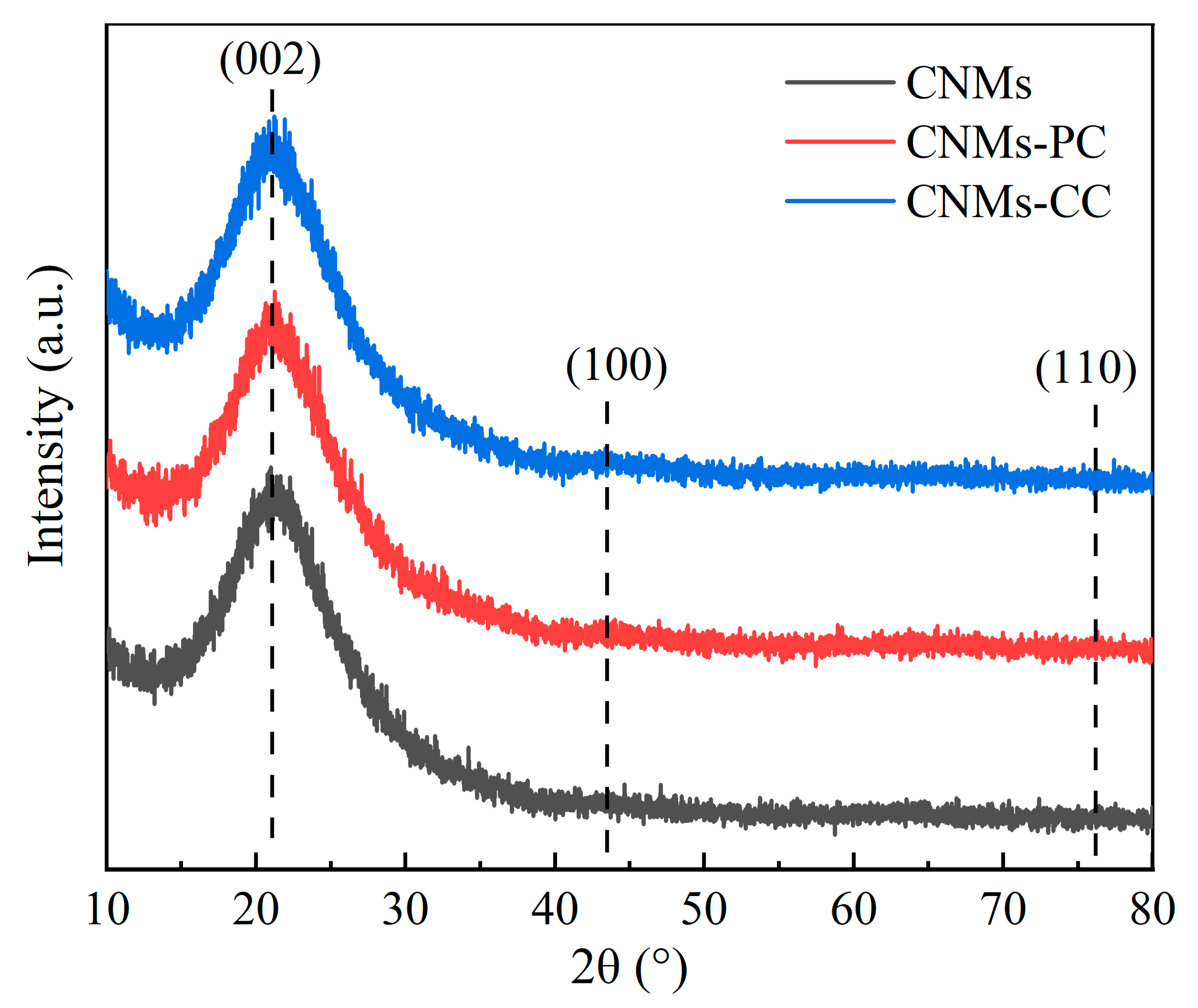
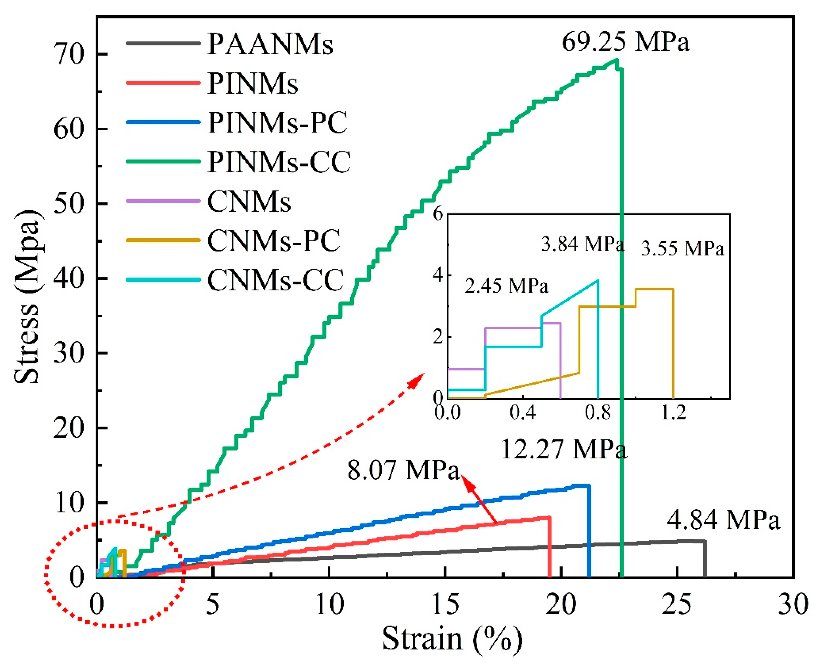
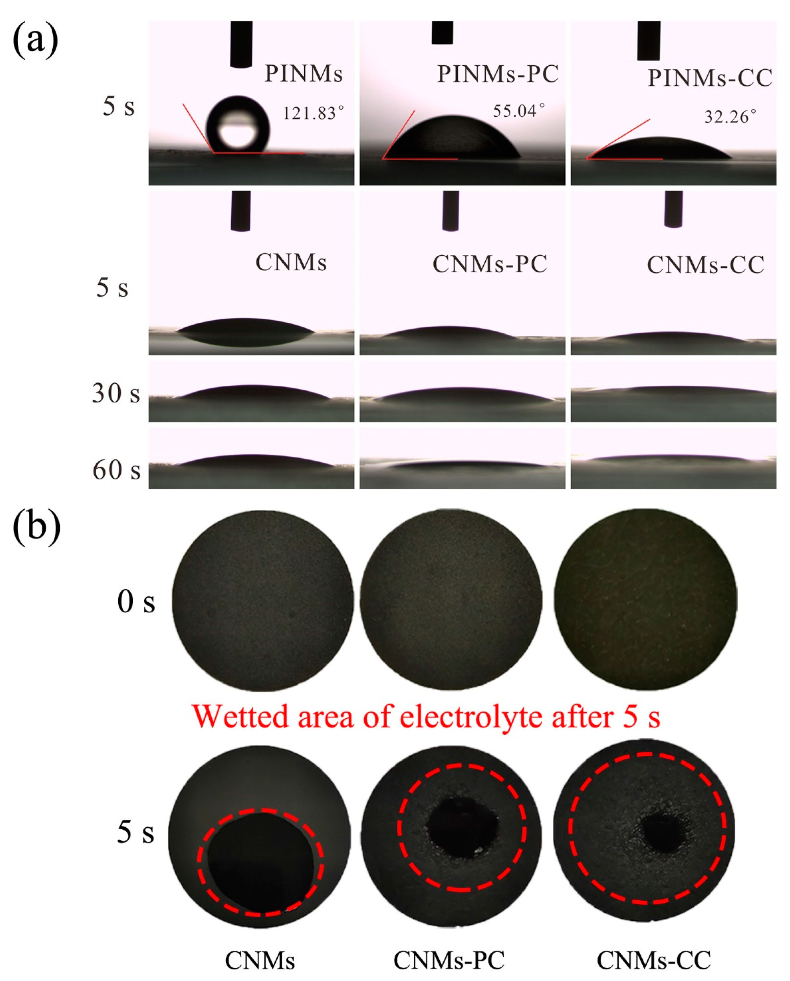
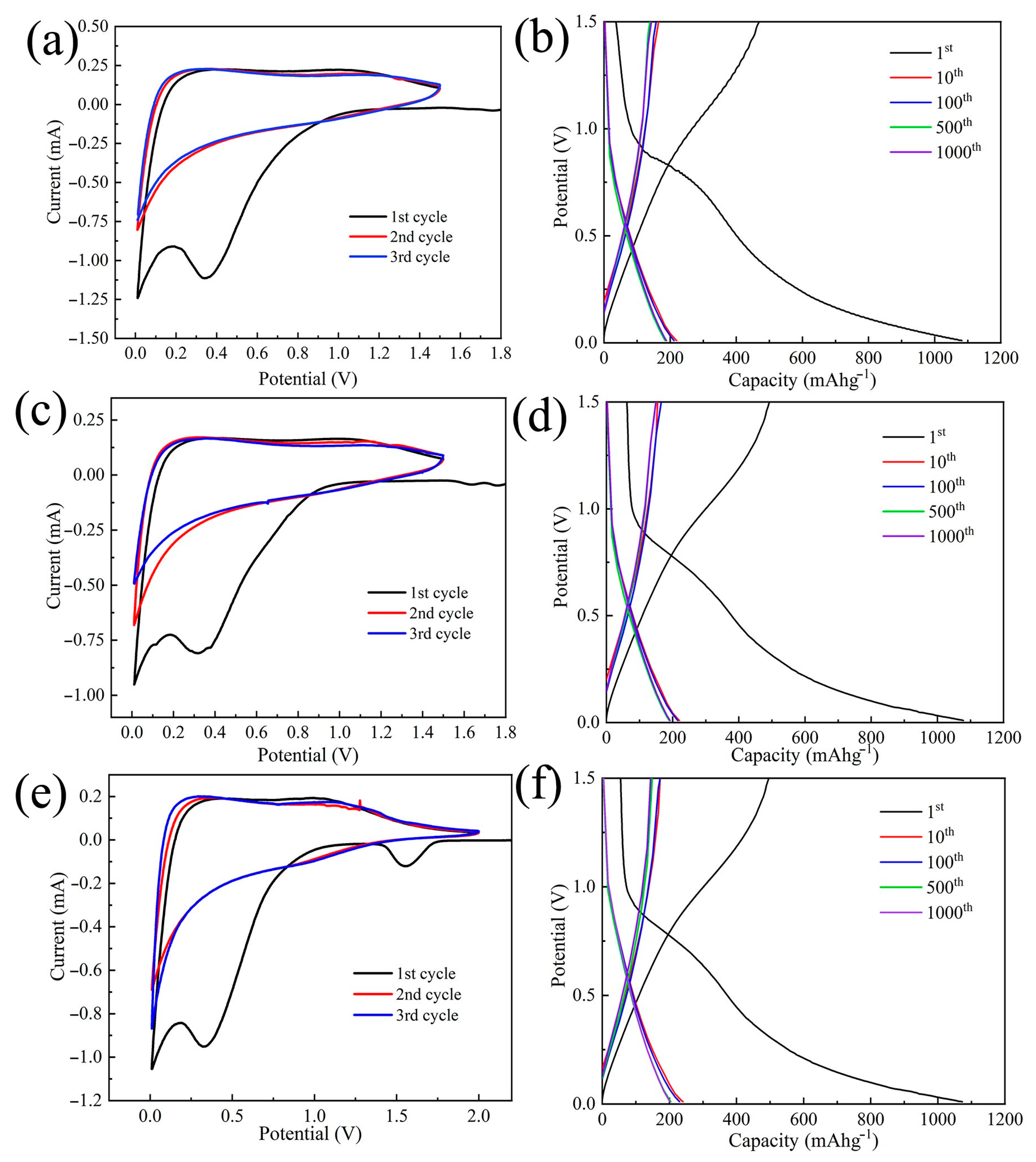
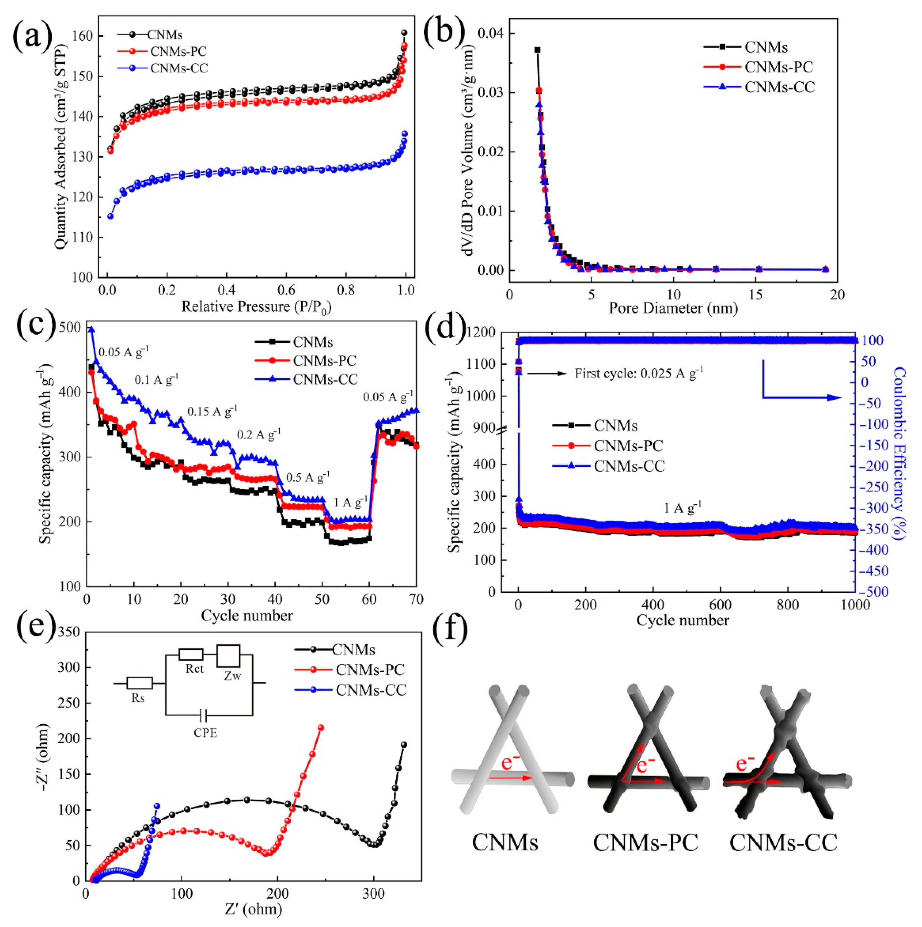
3. Results and Discussion

Figure 2 shows the infrared characterization spectrum of the as-prepared PI membranes. On the one hand, the appearance of the characteristic absorption peaks of the five-membered imine ring in the main chain of PI proves that PI has been successfully obtained, which is the C=O symmetric stretching vibration absorption peak on the imide ring at 1776 cm−1. The asymmetric stretching vibration peak of imide bond corresponds to 1725 cm−1. The peak at 1375 cm−1 belongs to C-N stretching vibration absorption peak on imide ring. The stretching vibration peak of C-O-C bond and the stretching vibration peak of the representative imide ring are the peaks of 1243 and 725 cm−1, respectively. It is proved that the samples are completely imidized and the structure is consistent with the target polymer. On the other hand, the peaks at 1562–1685 cm−1 and the peak at 3440 cm−1 representing the free amine groups in the system almost disappeared after imidization, including unreacted amine groups and free amine groups on the molecular chain. The disappearance of the characteristic absorption peaks of PAA indicates that the PAA membranes have finished imidization. The characteristic absorption peaks of the chemical bonds and characteristic functional groups of the polymer do not change with the crosslinking treatment conditions.
The effects of crosslinking treatment on the thermal stability of PI membranes were analyzed by TG and DSC tests in N2 atmosphere. Figure 3a is the thermal weight loss curve of samples under nitrogen protection, exhibiting the inherent thermal stability of PI membranes. Firstly, an obvious plateau exists before 500 °C, suggesting that PI has good heat resistance. Secondly, a sharp drop of the curve from 500 °C to 700 °C shows the significant loss of mass, which means that PI membranes undergo a violent decomposition reaction. Notably, at 500 °C, PINMs, PINMs-PC and PINMs-CC lose 2.47%, 2.27% and 1.83% by weight, respectively, indicating that the crosslinking structure strengthens the molecular chains and slightly improves the heat resistance performance. The formation of the crosslinking structure is beneficial to increase the glass transition temperature (Tg) of membranes as seen from DSC curve (Figure 3b). Notably, the mass retention rates of CNMs, CNMs-PC and CNMs-CC are 58.45%, 58.61% and 57.74%, respectively, at 700 °C. The thermogravimetric analysis indicates that morphology of nanofibers has changed from the initial cylindrical structure to a flat structure, which is more conducive to the evaporation of non-carbon atoms in the carbonization process.
The surface and cross-section morphologies of CNMs-CC, CNMs, and CNMs-PC are shown in Figure 4. Many crosslinking points are formed in the CNMs-CC sample as shown in Figure 4a due to the triple crosslinking strategy, which are marked with red dotted lines. The 3D network structure of CNMs-CC facilitates the wetting of electrolyte and electron transport. From the cross-section morphology shown in Figure 4d, a dense lamellar structure is formed between layers, which is beneficial to the improvement of mechanical strength. As references, Figure 4b,c,e,f are the surface and cross-section morphologies of CNMs and CNMs-PC, respectively. There are many smooth cylindrical fibers in CNMs as shown in Figure 4b,e. The fibers are loosely lapped and stacked together to form fluffy voids, exhibiting the morphological characteristics of non-woven fabrics. After physical rolling, the fibers of CNMs-PC display flattened forms and very few crosslinking points could be observed on the cross-section of the fibers.
The crystal structures of CNMs, CNMs-PC and CNMs-CC are observed by X-ray diffraction patterns (XRD), as shown in Figure 5. The diffraction peaks of CNMs-CC are similar to those of CNMs and CNMs-PC. There is no obvious difference in the structural order of the aggregated state, indicating that the crystal structure is less affected the triple crosslinking strategy. “Steamed bun” like peaks at approximately 2θ = 20° are considered as diffuse diffraction peaks caused by amorphous structures in the molecules, suggesting that the composition of the prepared samples is still dominated by amorphous carbon [34,35,36]. Since the carbonization temperature is not high enough relative to the graphitization temperature, the samples have not yet turned into the structure of graphite. The radial arrangement of molecules is disrupted, with tiny crystals, an undeveloped structure and irregular arrangement. In addition, the polyimide of PMDA/ODA owns the planar molecular structure, and the presence of ether bonds disturbs the orientation regularity of the molecular chain. The axial lateral stacking density of the molecular chain is small, which is not conducive to obtaining graphite microcrystals with large crystallite dimensions.
In general, the mechanical strength can be improved by making the structure dense through physical rolling. As shown in Figure 6, the tensile strength of the original PAANMs is only 4.84 MPa. However, the tensile strengths of PINMs and PINMs-PC are 8.07 and 12.27 MPa, respectively. Furthermore, the tensile strength of PINMs-CC increases to as high as 69.25 MPa, demonstrating that the triple crosslinking approach effectively and substantially improves the mechanical properties of PINMs through the formation of a large number of physical intersection points. By previous thermogravimetric analysis, the PI precursor shows excellent heat resistance due to the retention of the aromatic amide structure, which leads to the fiber membranes maintaining high mechanical properties. After carbonization, there is a dramatic decrease in mass and gas release that occurs inside the membranes due to the breakage and reorganization of molecular bonds, resulting in a significant decrease in mechanical properties, which is consistent with the results in Figure 3 and Figure 5. Nevertheless, the mechanical strength of the CNMs-CC with the value of 3.84 MPa is still highest, which proves that the novel triple crosslinking strategy on carbon nanofiber membranes is effective and efficient.
In general, excellent compatibility between the liquid electrolyte and the electrode will reduce the internal resistance and facilitate ion conduction, which is expected to further improve the electrochemical performance of the LIBs. Therefore, the contact angle test was carried out to characterize the wettability of as-prepared samples, in which the deionized water as the dropping liquid, as shown in Figure 7a. It is obvious to see that the contact angles of the PINMs, PINMs-PC and PINMs-CC after 5 s are 121.83°, 55.04° and 32.26°, respectively, as shown in Figure 7a. After carbonization, the wettability of the corresponding carbon membranes can be further improved due to their higher surface energy. CNMs-CC with a triple crosslinking structure exhibits the best wettability. To further investigate the wettability of samples to electrolyte in battery applications, liquid electrolytes were employed to drop on the surface of the CNMs, CNMs-PC and CNMs-CC. The wetting areas of the droplets on the surfaces of samples were observed to characterize the differences in wettability, as shown in Figure 7b. It may be related to the effect of decomposition on the membrane surface and the size of the micro-crystals formed during carbonization. However, the specific reasons need to be further studied.
As shown in Figure 8, XPS is employed to describe the elemental species and the valence of N. Figure 8a shows the survey scan spectra of C, O and N. As expected, the N content is increased by the NH3 treatment (Figure 8b). The N content of the CNMs-CC with NH3 activation (5.74%) is higher than that of CNMs-CC before NH3 treatment (4.64%). The configurations of N before and after NH3 treatment are depicted in Figure 8c,d, respectively. It can be classified into three configurations by split-peak fitting, including graphitic nitrogen, pyrrole nitrogen and pyridine nitrogen at 398.4, 400.8 and 403.1 eV, respectively. Pyridine N and graphitic N can increase the electronic conductivity due to sp2 hybridized orbitals [37,38,39]. Therefore, the surface treatment with NH3 can increase the surface activity of carbon fibers while etching the surface, indicating that NH3 is of great benefit for the improvement of electrochemical properties [40,41,42].
As discussed before, PI molecular chain contains many benzene rings and aromatic heterocyclic structures, and the molecular chain breaks to form benzene ring radicals during heat treatment. Further increasing the carbonization temperature, the benzene ring radicals condense and polymerize with each other to form a hexagonal carbon network plane. The electron orbitals overlap a lot, which makes the PI-based carbon fiber have certain electrical conductivity [43,44]. The conductivities of CNMs, CNMs-PC and CNMs-CC were listed in Table 1 with the values of 10.22, 22.30, and 41.91 S/m, respectively. Obviously, the CNMs-CC shows excellent electron conductivity, which is owing to the unique triple crosslinking structure and the significant increase in crosslinking points.
As shown in Figure 9, CNMs-CC, CNMs and CNMs-PC display typical characteristics of hard carbon materials by CV and charge/discharge tests. Figure 9a,c,e show the CV curves of CNMs, CNMs-PC and CNMs-CC, of which these samples were used as anodes and metallic Li served as counter electrode. Two irreversible peaks of CV curve for CNMs-CC appeared at 0.4 and 1.5 V during the first cycle, which may be associated with the formation of solid electrolyte interphase (SEI), as the peaks disappeared during the last two cycles. After the first cycle, the curves are almost overlapped, exhibiting stable lithium-ion insertion-extraction behavior. Likewise, the charge/discharge curves of CNMs, CNMs-PC and CNMs-CC are shown in Figure 9b,d,f. In line with the CV curve, there is a voltage drop plateau at 0.2–0.8 V in the first cycle due to the SEI film [45,46,47]. Similarly, compared with CNMs and CNMs-PC, voltage plateau regions of the charge–discharge profiles for CNMs-CC also disappeared in the subsequent cycles. The capacity degradation happens dominantly during the initial cycle. The detailed parameters of the carbon electrodes during charging and discharging are summarized in Table 2.
The initial discharge capacity of CNMs-CC (1072.70 mAh g−1) is amazing, which is almost three times higher than that of commercial graphite anodes. However, owing to the highly irreversible formation of SEI film, the initial Coulomb efficiencies of CNMs, CNMs-PC and CNMs-CC are only 49.40%, 49.42% and 50.06%, respectively. Therefore, the tests results reveal that the novel triple crosslinking strategy on carbon nanofiber membranes as flexible electrodes is beneficial to improve the first Coulomb efficiency to some extent.
To characterize the porous texture, among the most important physicochemical properties of carbon-based materials, the N2 adsorption-desorption isotherms and pore size distribution curves are depicted in Figure 10a,b. All three curves are typed I adsorption curves. The adsorption and desorption plateaus decrease sequentially, which indicates that CNMs-CC has the lowest specific surface area. By calculation, the BET surface areas of CNMs, CNMs-PC and CNMs-CC are 459.35, 452.84, and 398.43 m2/g and the average pore sizes are 0.25, 0.24, and 0.20 cm3/g, respectively. Meanwhile, the sample surface exists mainly as a microporous structure, which can be judged by the almost horizontal curves with the P/P0 value between 0.2 and 0.8. Thus, the high specific surface area of electrode offers larger electrolyte/electrode interfaces and more active sites for Li+ adsorption during charging and discharging. Meanwhile, SEI film is associated with the specific surface area of the carbon membranes, so the generated irreversible capacity loss strongly depends on the specific surface area [48].
The rate performances of CNMs, CNMs-PC and CNMs-CC at various current densities are plotted in Figure 10c. CNMs-CC exhibits high stability with capacities of 495, 384, 339, 307, 260 and 213 mAh g−1 at current densities of 0.05, 0.1, 0.15, 0.2, 0.5, and 1 A g−1, respectively. However, the reversible capacity of CNMs and CNMs-PC are poorer than that of CNMs-CC at all current densities. Notably, CNMs-CC shows excellent cycling performance after 1000 cycles (Figure 10d), even at a high current density. The three electrodes exhibit excellent cycling stability and all show similar capacity decay rates. CNMs, CNMs-PC and CNMs-CC deliver discharge capacities of 265.51, 271.08 and 290.87 mAh g−1, respectively. After 1000 cycles, they remain 188.68, 191.86, and 201.38 mAh g−1, respectively. Compared to CNMs and CNMs-PC, CNMs-CC shows best rate and cycling performances, which can be attributed to the synergistic effects of its stable triple crosslinking structure, good wettability, electrical conductivity, and smaller impedance. The crosslinking network structure provides 3D fast electron paths, as evidenced by four-point probe measurements (Table 2).
EIS measurements are performed as shown in Figure 10e. The curve consists of a semicircle related to the charge transfer impedance and a diagonal line corresponding to the resistance to Li+ diffusion [49,50]. By comparison, the semicircle of CNMs-CC is smallest, demonstrating higher electron conductivity, which is particularly critical to enhance electrode rate performance. The specific values were obtained by fitting with ZVIEW, as shown in Table 3. Moreover, the triple crosslinking network structure of CNMs-CC is more compact, which can form 3D electron transport pathway through the intersection points caused by the novel triple crosslinking strategy, as demonstrated in Figure 10f. Furthermore, the Li+ transport distance is shortened to improve the electrochemical performance of LIBs. Compared with the conventional electrodes, the self-supporting flexible carbon nanofiber membranes does not require grinding and coating processes, greatly reducing the process flow. When used as electrodes, the flexible carbon nanofiber membranes not only serve as lithium-ion charge and discharge of the active material carrier, but also serve as fluid collector for electron collection.
To further explore the changes in CNMs-CC morphology after charging and discharging, Figure 11 shows the SEM morphologies of CNMs, CNMs-PC, CNMs-CC as flexible electrodes after 1000 cycles. Compared with CNMs and CNMs-PC, the surface of CNMs-CC is more tightly covered by small particles and the SEI film is more uniform. The fibers of CNMs-PC remain flat and the morphologies of CNMs are very consistent, basically maintaining the cylindrical fiber shape before cycling. The surface is covered by small particles, which is related to SEI film. As is known to all, a stable SEI film is crucial to the battery performance, because it can effectively prevent the damage of electrodes by co-embedding of solvent molecules and improve the cycling performance. As seen in Figure 11, the freestanding 3D network structure significantly suppresses the volume expansion effect during lithium embedding and de-embedding. Therefore, the CNMs-CC with stable SEI film exhibits more excellent electrochemical performance, which has been proved in the characterization of rate and cycle performances.

4. Conclusions

In summary, a triple crosslinking strategy was put forward to fabricate carbon nanofiber membranes via synergistic action of pre-rolling, solvent and chemical imidization. The novel crosslinking structure grants CNMs-CC many advantages, including excellent mechanical properties and wettability, especially electrical conductivity and fast charge transfer capability. The CNMs-CC exhibits excellent electrochemical performances, such as a good reversible capacity of 495 mAh g−1, superior rate capability with current densities from 0.05 to 1 A g−1 and an ultra-long cycling stability of 201.38 mAh g−1 over 1000 cycles at 1 A g−1. Furthermore, it can withstand the repeated impacts of lithium ions during charging and discharging owing to strong structural stability. Therefore, considering their excellent performance, flexibility, simple synthesis process and low cost, CNMs-CC could be promising binder-free anodes for flexible batteries and supercapacitors.

Author Contributions

H.X.: conceptualization, methodology, visualization, investigation, funding acquisition, and writing—original draft; X.H.: validation, methodology, formal analysis, and software; M.G.: data curation and visualization; C.Y. (Changshu Yang): methodology; J.L.: investigation; Y.C.: investigation; L.M.: funding acquisition; L.Z.: resources and project administration; C.Y. (Chuanqiang Yin): conceptualization and writing—review and editing; X.L.: funding acquisition, supervision, project administration, and writing—review and editing. All authors have read and agreed to the published version of the manuscript.

Funding

This work was financially supported by the Youth Long-term Project of Jiangxi Province to Introduce Leading Innovative Talents, China (Grant No. jxsq2018106023), the Guangxi Key Laboratory of Information Materials (211012-K), and the Postgraduate Innovation Special Fund Project of Jiangxi Province, China (Grant No. YC2021-S121).

Institutional Review Board Statement

Not applicable.

Informed Consent Statement

Not applicable.

Data Availability Statement

The data that support the findings of this study are available from the corresponding author upon reasonable request.

Conflicts of Interest

The authors declare no conflict of interest.

References

  1. Zhang, Y.; Jiao, Y.D.; Liao, M.; Wang, B.J.; Peng, H.S. Carbon nanomaterials for flexible lithium ion batteries. Carbon 2017, 124, 79–88. [Google Scholar] [CrossRef]
  2. Lee, B.S. A review of recent advancements in electrospun anode materials to improve rechargeable lithium battery performance. Polymers 2020, 12, 2035. [Google Scholar] [CrossRef] [PubMed]
  3. Kim, C.; Yang, K.S.; Kojima, M.; Yoshida, K.; Kim, Y.J.; Kim, Y.A.; Endo, M. Fabrication of electrospinning-derived carbon nanofiber webs for the anode material of lithium-ion secondary batteries. Adv. Funct. Mater. 2006, 16, 2393–2397. [Google Scholar] [CrossRef]
  4. Zhang, M.; Lu, R.C.; Yuan, H.X.; Amin, K.R.; Mao, L.J.; Yan, W.; Wei, Z.X. Nanowire array-coated flexible substrate to accommodate lithium plating for stable lithium-metal anodes and flexible lithium-organic batteries. ACS Appl. Mater. Inter. 2019, 11, 20873–20880. [Google Scholar] [CrossRef] [PubMed]
  5. Huang, J.Q.; Peng, H.J.; Liu, X.Y.; Nie, J.Q.; Cheng, X.B.; Zhang, Q.; Wei, F. Flexible all-carbon interlinked nanoarchitectures as cathode scaffolds for high-rate lithium-sulfur batteries. J. Mater. Chem. A 2014, 2, 10869–10875. [Google Scholar] [CrossRef]
  6. Lu, X.H.; Zhai, T.; Zhang, X.H.; Shen, Y.Q.; Yuan, L.Y.; Hu, B.; Gong, L.; Chen, J.; Gao, Y.H.; Zhou, J.; et al. WO3-x@Au@MnO2 core-shell nanowires on carbon fabric for high-performance flexible supercapacitors. Adv. Mater. 2012, 24, 938–944. [Google Scholar] [CrossRef]
  7. Yousaf, M.; Shi, H.T.H.; Wang, Y.S.; Chen, Y.J.; Ma, Z.M.; Cao, A.Y.; Naguib, H.E.; Han, R.P.S. Novel pliable electrodes for flexible electrochemical energy storage devices: Recent progress and challenges. Adv. Energy Mater. 2016, 6, 1600490. [Google Scholar] [CrossRef]
  8. Lee, Y.K. The effect of active material, conductive additives, and binder in a cathode composite electrode on battery performance. Energies 2019, 12, 658. [Google Scholar] [CrossRef]
  9. Zhou, G.M.; Li, F.; Cheng, H.M. Progress in flexible lithium batteries and future prospects. Energy Environ. Sci. 2014, 7, 1307–1338. [Google Scholar] [CrossRef]
  10. Elazari, R.; Salitra, G.; Garsuch, A.; Panchenko, A.; Aurbach, D. Sulfur-impregnated activated carbon fiber cloth as a binder-free cathode for rechargeable Li-S batteries. Adv. Mater. 2011, 23, 5641–5644. [Google Scholar] [CrossRef]
  11. Ji, L.W.; Zhang, X.W. Fabrication of porous carbon/Si composite nanofibers as high-capacity battery electrodes. Electrochem. Commun. 2009, 11, 1146–1149. [Google Scholar] [CrossRef]
  12. Xia, L.; Wang, S.Q.; Liu, G.X.; Ding, L.X.; Li, D.D.; Wang, H.H.; Qiao, S.Z. Flexible SnO2/N-doped carbon nanofiber films as integrated electrodes for lithium-ion batteries with superior rate capacity and long cycle life. Small 2016, 12, 853–859. [Google Scholar] [CrossRef]
  13. Santangelo, S. Electrospun Nanomaterials for energy applications: Recent advances. Appl. Sci. 2019, 9, 1049. [Google Scholar] [CrossRef]
  14. Gee, S.; Johnson, B.; Smith, A.L. Optimizing electrospinning parameters for piezoelectric PVDF nanofiber membranes. J. Membrane Sci. 2018, 563, 804–812. [Google Scholar] [CrossRef]
  15. Ero-Phillips, O.; Jenkins, M.; Stamboulis, A. Tailoring crystallinity of electrospun Plla fibers by control of electrospinning parameters. Polymers 2013, 4, 1331–1348. [Google Scholar] [CrossRef]
  16. Barik, R.; Raulo, A.; Jha, S.; Nandan, B.; Ingole, P.P. Polymer-derived electrospun Co3O4@C porous nanofiber network for flexible, high-performance, and stable supercapacitors. ACS Appl. Energy Mater. 2020, 3, 11002–11014. [Google Scholar] [CrossRef]
  17. Zhao, B.T.; Cai, R.; Jiang, S.M.; Sha, Y.J.; Shao, Z.P. Highly flexible self-standing film electrode composed of mesoporous rutile TiO2/C nanofibers for lithium-ion batteries. Electrochim. Acta. 2012, 85, 636–643. [Google Scholar] [CrossRef]
  18. Noerochim, L.; Wang, J.Z.; Chou, S.L.; Wexler, D.; Liu, H.K. Free-standing single-walled carbon nanotube/SnO2 anode paper for flexible lithium-ion batteries. Carbon 2012, 50, 1289–1297. [Google Scholar] [CrossRef]
  19. Xu, H.; Yin, C.Q.; Hou, X.R.; Gong, M.; Yang, C.S.; Xu, L.X.; Luo, J.P.; Ma, L.; Zhou, L.; Li, X.M. Polyimide-derived carbon nanofiber membranes as free-standing anodes for lithium-ion batteries. RSC Adv. 2022, 12, 21904–21915. [Google Scholar] [CrossRef]
  20. Kuroda, S.; Tobori, N.; Sakuraba, M.; Sato, Y. Charge-discharge properties of a cathode prepared with ketjen black as the electro-conductive additive in lithium ion batteries. J. Power Sources 2003, 119, 924–928. [Google Scholar] [CrossRef]
  21. Nataraj, S.K.; Yang, K.S.; Aminabhavi, T.M. Polyacrylonitrile-based nanofibers A state-of-the-art review. Prog. Polym. Sci. 2012, 37, 487–513. [Google Scholar] [CrossRef]
  22. Jin, J.; Shi, Z.Q.; Wang, C.Y. Electrochemical performance of electrospun carbon nanofibers as free-standing and binder-free anodes for sodium-ion and lithium-ion batteries. Electrochim. Acta. 2014, 141, 302–310. [Google Scholar] [CrossRef]
  23. Chen, L.; Shen, Z.G.; Liu, J.; Liang, J.Y.; Wang, X.X. Effects of oxygen on the structural evolution of polyacrylonitrile fibers during rapid thermal treatment. RSC Adv. 2020, 10, 6356–6361. [Google Scholar] [CrossRef] [PubMed]
  24. Yang, K.S.; Kim, C.; Park, S.H.; Kim, J.H.; Lee, W.J. Fabrications and electrochemical properties of activated carbon nanofibers from electrospinning of various polymers. J. Biomed. Nanotechnol. 2006, 2, 103–105. [Google Scholar] [CrossRef]
  25. Vanherck, K.; Koeckelberghs, G.; Vankelecom, I.F.J. Crosslinking polyimides for membrane applications: A review. Prog. Polym. Sci. 2013, 38, 874–896. [Google Scholar] [CrossRef]
  26. Zhang, Z.X.; Du, H.D.; Li, J.; Gan, L.; Chiang, S.W.; Li, B.H.; Kang, F.Y. Preparation of aligned polyimide-based carbon nanofibers by electrospinning. New Carbon Mater. 2015, 30, 289–294. [Google Scholar] [CrossRef]
  27. Wang, J.G.; Yang, Y.; Huang, Z.H.; Kang, F.Y. MnO-carbon hybrid nanofiber composites as superior anode materials for lithium-ion batteries. Electrochim. Acta. 2015, 170, 164–170. [Google Scholar] [CrossRef]
  28. Zang, K.J.; Han, P.X.; Gu, L.; Zhang, L.X.; Liu, Z.H.; Kong, Q.S.; Zhang, C.J.; Dong, S.M.; Zhang, Z.Y.; Yao, J.H.; et al. Synthesis of Nitrogen-doped MnO/graphene nanosheets hybrid material for lithium ion batteries. ACS Appl. Mater. Inter. 2012, 4, 658–664. [Google Scholar] [CrossRef]
  29. Wan, H.R.; Hu, X.F. Nitrogen doped biomass-derived porous carbon as anode materials of lithium ion batteries. Solid State Ionics. 2019, 341, 115030. [Google Scholar] [CrossRef]
  30. He, Z.X.; Jiang, Y.Q.; Meng, W.; Zhu, J.; Liu, Y.; Dai, L.; Wang, L. Advanced LiTi2(PO4)3@N-doped carbon anode for aqueous lithium ion batteries. Electrochim. Acta. 2016, 222, 1491–1500. [Google Scholar] [CrossRef]
  31. Zhao, F.Y.; Zhao, X.; Peng, B.; Gan, F.; Yao, M.Y.; Tan, W.J.; Dong, J.; Zhang, Q.H. Polyimide-derived carbon nanofiber membranes as anodes for high-performance flexible lithium ion batteries. Chin. Chem. Lett. 2017, 29, 1692–1697. [Google Scholar] [CrossRef]
  32. Jiang, Q.T.; Pang, X.; Geng, S.T.; Zhao, Y.H.; Wang, X.M.; Qin, H.; Liu, B.; Zhou, J.; Zhou, T. Simultaneous cross-linking and pore-forming electrospun carbon nanofibers towards high capacitive performance. Appl. Surf. Sci. 2019, 479, 128–136. [Google Scholar] [CrossRef]
  33. Ma, Z.Q.; Li, X.X. The study on microstructure and electrochemical properties of Al-Mg-Sn-Ga-Pb alloy anode material for Al/AgO battery. J. Solid State Electr. 2011, 15, 2601–2610. [Google Scholar] [CrossRef]
  34. Yang, T.H.; Guo, Y.L.; Zhou, X.C.; Liu, Y.M. Preparation of amorphous carbon-coated nano-scale SnO2 and its performance for anode material of lithium ion secondary battery. J. Inorg. Mater. 2009, 24, 147–151. [Google Scholar] [CrossRef]
  35. Yu, X.L.; Zhang, K.Y.; Tian, N.; Qin, A.M.; Liao, L.; Du, R.; Wei, C. Biomass carbon derived from sisal fiber as anode material for lithium-ion batteries, ScienceDirect. Mater. Lett. 2015, 142, 193–196. [Google Scholar] [CrossRef]
  36. Groult, H.; Kaplan, B.; Lantelme, F.; Komaba, S.; Kumagai, N.; Yashiro, H.; Nakajima, T.; Simon, B.; Barhoun, A. Preparation of carbon nanoparticles from electrolysis of molten carbonates and use as anode materials in lithium-ion batteries. Solid State Ion. 2006, 177, 869–875. [Google Scholar] [CrossRef]
  37. Cao, Y.; Si, W.M.; Zhang, Y.H.; Hao, Q.L.; Lei, W.; Xia, X.F.; Li, J.; Wang, F.G. Nitrogen-doped graphene: Effect of graphitic-N on the electrochemical sensing properties towards acetaminophen. Flatchem 2018, 9, 1–7. [Google Scholar] [CrossRef]
  38. Peng, P.; Liu, H.T.; Wu, B.; Tang, Q.X.; Liu, Y.Q. Nitrogen doped graphene with a p-type field-effect and its fine modulation. Acta Phys.-Chim. Sin. 2019, 35, 1282–1290. [Google Scholar] [CrossRef]
  39. Li, G.C.; Huang, Y.L.; Yin, Z.L.; Guo, H.J.; Liu, Y.; Cheng, H.; Wu, Y.P.; Ji, X.B.; Wang, J.X. Defective synergy of 2D graphitic carbon nanosheets promotes lithium-ion capacitors performance. Energy Storage Mater. 2019, 24, 304–311. [Google Scholar] [CrossRef]
  40. Ko, J.H.; Park, R.S.; Jeon, J.K.; Kim, D.H.; Jung, S.C.; Kim, S.C.; Park, Y.K. Effect of surfactant, HCl and NH3 treatments on the regeneration of waste activated carbon used in selective catalytic reduction unit. J. Ind. Eng. Chem. 2015, 32, 109–112. [Google Scholar] [CrossRef]
  41. Badey, J.P.; Urbaczewski-Espuche, E.; Jugnet, Y.; Sage, D.; Duc, T.M.; Chabert, B. Surface modification of polytetrafluoroethylene by microwave plasma downstream treatment. Polymer 1994, 35, 2472–2479. [Google Scholar] [CrossRef]
  42. Nan, D.; Huang, Z.H.; Lv, R.T.; Yang, L.; Wang, J.G.; Shen, W.C.; Lin, Y.X.; Yu, X.L.; Ye, L.; Sun, H.Y.; et al. Nitrogen-enriched electrospun porous carbon nanofiber networks as high-performance free-standing electrode materials. J. Mater. Chem. A 2014, 2, 19678–19684. [Google Scholar] [CrossRef]
  43. Tian, G.F.; Zhang, H.P.; Liu, J.N.; Qi, S.L.; Wu, D.Z. Enhanced conductivity and mechanical properties of polyimide based nanocomposite materials with carbon nanofibers via carbonization of electrospun polyimide fibers. Polym. Sci. Ser. A 2014, 56, 505–510. [Google Scholar] [CrossRef]
  44. Lu, Y.H.; Hao, J.C.; Xiao, G.Y.; Chen, L.; Wang, T.H.; Hu, Z.Z. Preparation and properties of in situ amino-functionalized graphene oxide/polyimide composite films. Appl. Surf. Sci. 2017, 422, 710–719. [Google Scholar] [CrossRef]
  45. Ji, L.W.; Gu, M.; Shao, Y.Y.; Li, X.L.; Engelhard, M.H.; Arey, B.W.; Wang, W.; Nie, Z.M.; Xiao, J.; Wang, C.M.; et al. Controlling SEI formation on SnSb-porous carbon nanofibers for improved Na ion storage. Adv. Mater. 2014, 26, 2901–2908. [Google Scholar] [CrossRef]
  46. Li, N.W.; Yin, Y.X.; Yang, C.P.; Guo, Y.G. An artificial solid electrolyte interphase layer for stable lithium metal anodes. Adv. Mater. 2016, 28, 1853–1858. [Google Scholar] [CrossRef]
  47. Heiskanen, S.K.; Kim, J.; Lucht, B.L. Generation and evolution of the solid electrolyte interphase of lithium-ion batteries. Joule 2019, 3, 2322–2333. [Google Scholar] [CrossRef]
  48. Lin, Y.X.; Liu, Z.; Leung, K.; Chen, L.Q.; Lu, P.; Qi, Y. Connecting the irreversible capacity loss in Li-ion batteries with the electronic insulating properties of solid electrolyte interphase (SEI) components. J. Power Sources 2016, 309, 221–230. [Google Scholar] [CrossRef]
  49. Bai, Z.Y.; Tu, W.M.; Zhu, J.K.; Li, J.S.; Deng, Z.; Li, D.P.; Tang, H.L. POSS-derived synthesis and full life structural analysis of Si@C as Anode Material in lithium ion battery. Polymers 2019, 11, 576. [Google Scholar] [CrossRef]
  50. Mizuno, Y.; Okubo, M.; Asakura, D.; Saito, T.; Hosono, E.; Saito, Y.; Oh-ishi, K.; Kudo, T.; Zhou, H.S. Impedance spectroscopic study on interfacial ion transfers in cyanide-bridged coordination polymer electrode with organic electrolyte. Electrochim. Acta. 2012, 63, 139–145. [Google Scholar] [CrossRef]
Figure 1. Schematic illustration for fabrication process of carbon nanofiber membranes. (a) The chemical structure of PAA (polyimide precursors), (b) PAA nanofiber membranes (PAANMs) without any treatment, (c) PAANMs-PC, (d) PAANMs-CC, corresponding optical photographs of (e) PAANMs, (f) CNMs, (g) CNMs-PC, and (h) CNMs-CC in the bent state.
Polymers 14 03528 g001
Figure 2. FT−IR spectrum of PINMs, PINMs−PC and PINMs−CC.
Polymers 14 03528 g002
Figure 3. (a) TGA curve and (b) DSC curve of PI membranes at a heating rate of 10 °C/min under nitrogen atmosphere.
Polymers 14 03528 g003
Figure 4. Surface and cross-section morphologies of (a,d) CNMs-CC, (b,e) CNMs, and (c,f) CNMs-PC.
Polymers 14 03528 g004
Figure 5. X-ray diffraction patterns of CNMs, CNMs-PC and CNMs-CC.
Polymers 14 03528 g005
Figure 6. Stress–strain curves of samples.
Polymers 14 03528 g006
Figure 7. (a) Contact angle determination of PINMs, PINMs-PC, PINMs-CC, CNMs, CNMs-PC and CNMs-CC and (b) photographs of electrolyte wettability for CNMs, CNMs-PC and CNMs-CC.
Polymers 14 03528 g007
Figure 8. (a) XPS spectra, (b) ratios of N content, N1s spectra for (c) CNMs-CC before NH3 treatment and (d) CNMs-CC after NH3 treatment.
Polymers 14 03528 g008
Figure 9. CV curves of (a) CNMs, (c) CNMs−PC (e) CNMs−CC at 0.1 mVs−1 and discharge/charge profiles for (b) CNMs, (d) CNMs−PC and (f) CNMs−CC at a current density of 1A g−1.
Polymers 14 03528 g009
Figure 10. (a) N2 adsorption−desorption isotherms, (b) BJH adsorption pore size distribution, (c) rate performance, (d) cycling performance, (e) EIS (Nyquist plots), measured at an amplitude of 5 mV over a frequency range of 100 kHz−0.1 Hz, and (f) illustration of electron transfer for CNMs, CNMs−PC and CNMs−CC.
Polymers 14 03528 g010
Figure 11. SEM images of (a) CNMs, (b) CNMs-PC and (c) CNMs-CC after 1000 cycles.
Polymers 14 03528 g011
Table 1. The Resistivity and electrical conductivity of samples.
SamplesSquare Resistivity (Ω)Resistivity (Ω·cm)Electric Conductivity (S/m)
CNMs1087.36 9.78 10.22
CNMs-PC738.27 4.4822.30
CNMs-CC588.52 2.3941.91
Table 2. The parameters of charge/discharge cycle data of samples.
SamplesInitial Discharge Specific Capacity/(mAh g−1)Initial Charge Specific Capacity/(mAh g−1)Initial Coulomb Efficiency10th/(mAh g−1)100th (mAh g−1)1000th (mAh g−1)
CNMs1082.32534.6449.40%219.61211.66188.68
CNMs-PC1078.14532.8649.42%220.44215.31191.86
CNMs-CC1072.70536.9550.06%240.38230.17201.38
Table 3. The parameters by fitting EIS spectra of samples.
SamplesRs (Ω)Rct (Ω)
CNMs10.9296.3
CNMs-PC5.8198.6
CNMs-CC9.348.1
Publisher’s Note: MDPI stays neutral with regard to jurisdictional claims in published maps and institutional affiliations.

