
The Influence of Pineapple Leaf Fiber Orientation and Volume Fraction on Methyl Methacrylate-Based Polymer Matrix for Prosthetic Socket Application

 ,
,  ,
,  and
and
Abstract
:1. Introduction
2. Materials and Method
2.1. Materials
2.2. Methods
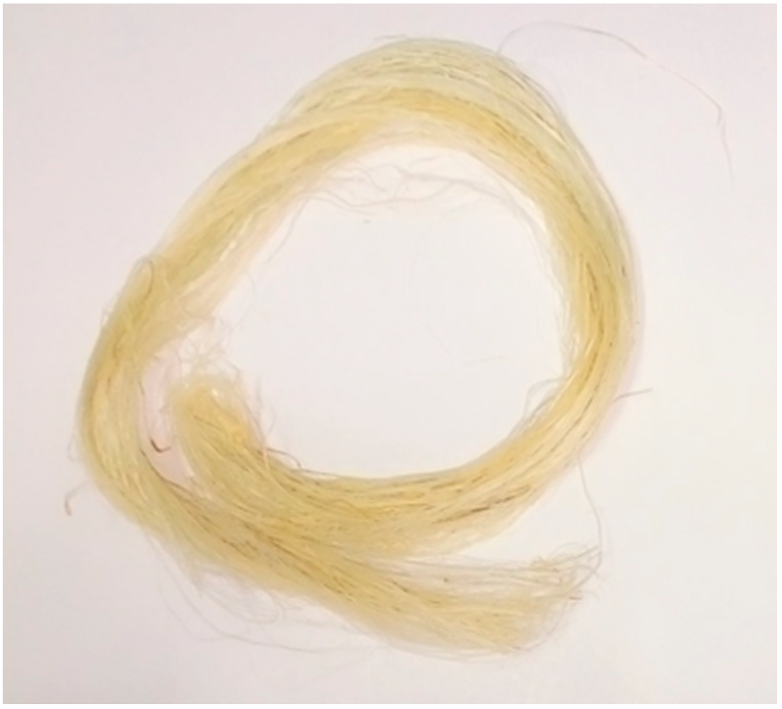
2.2.1. Treatment of PALF
2.2.2. Preparation of PALF/MMA Composites
2.2.3. Flexural Test
2.2.4. Micromechanical Models
Rule of Mixture (RoM)
Modified Rule of Mixtures (MRoM)
Halpin–Tsai (H–T) Model
2.2.5. Statistical Data Analysis
3. Results
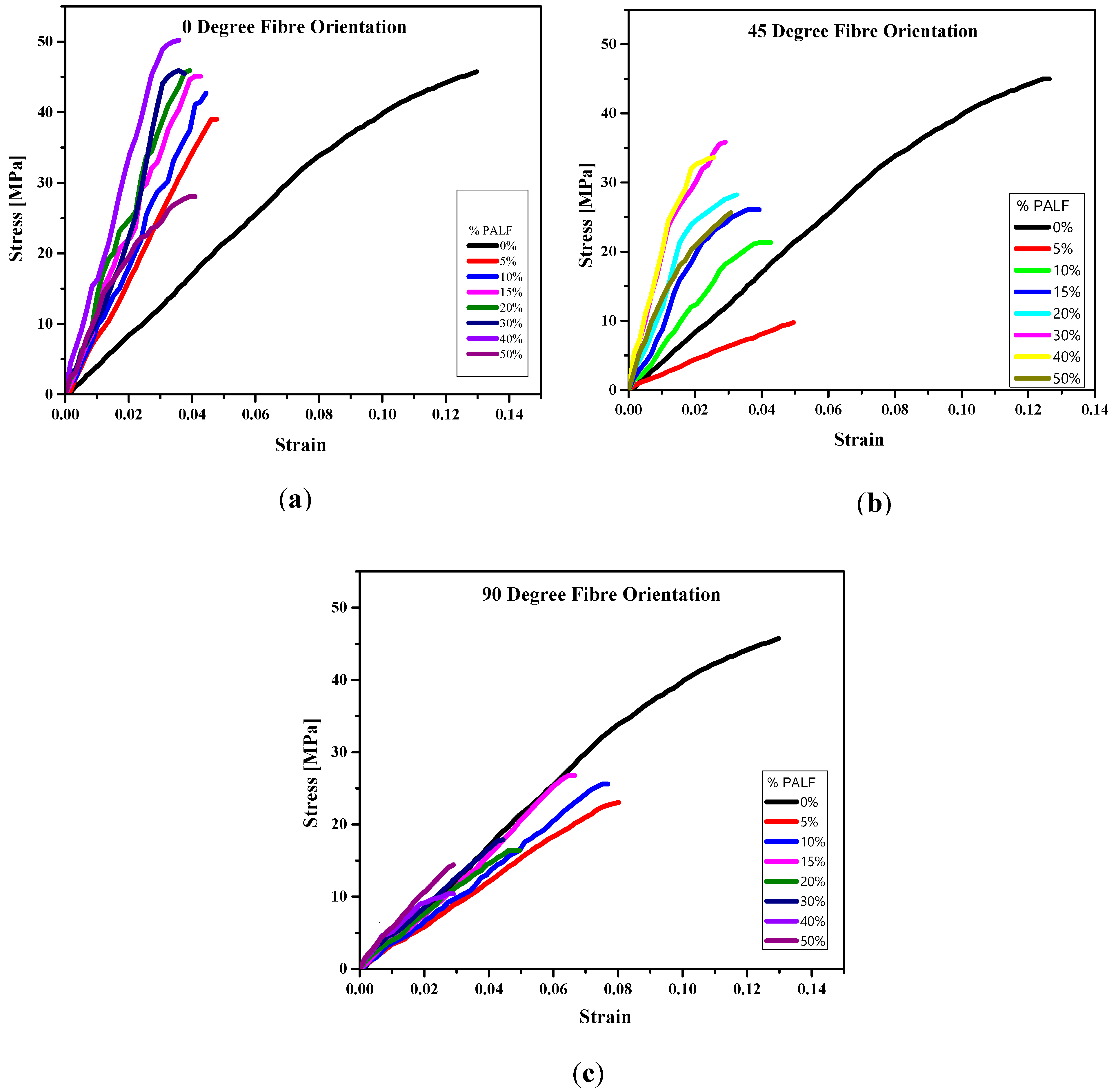
3.1. Flexural Test
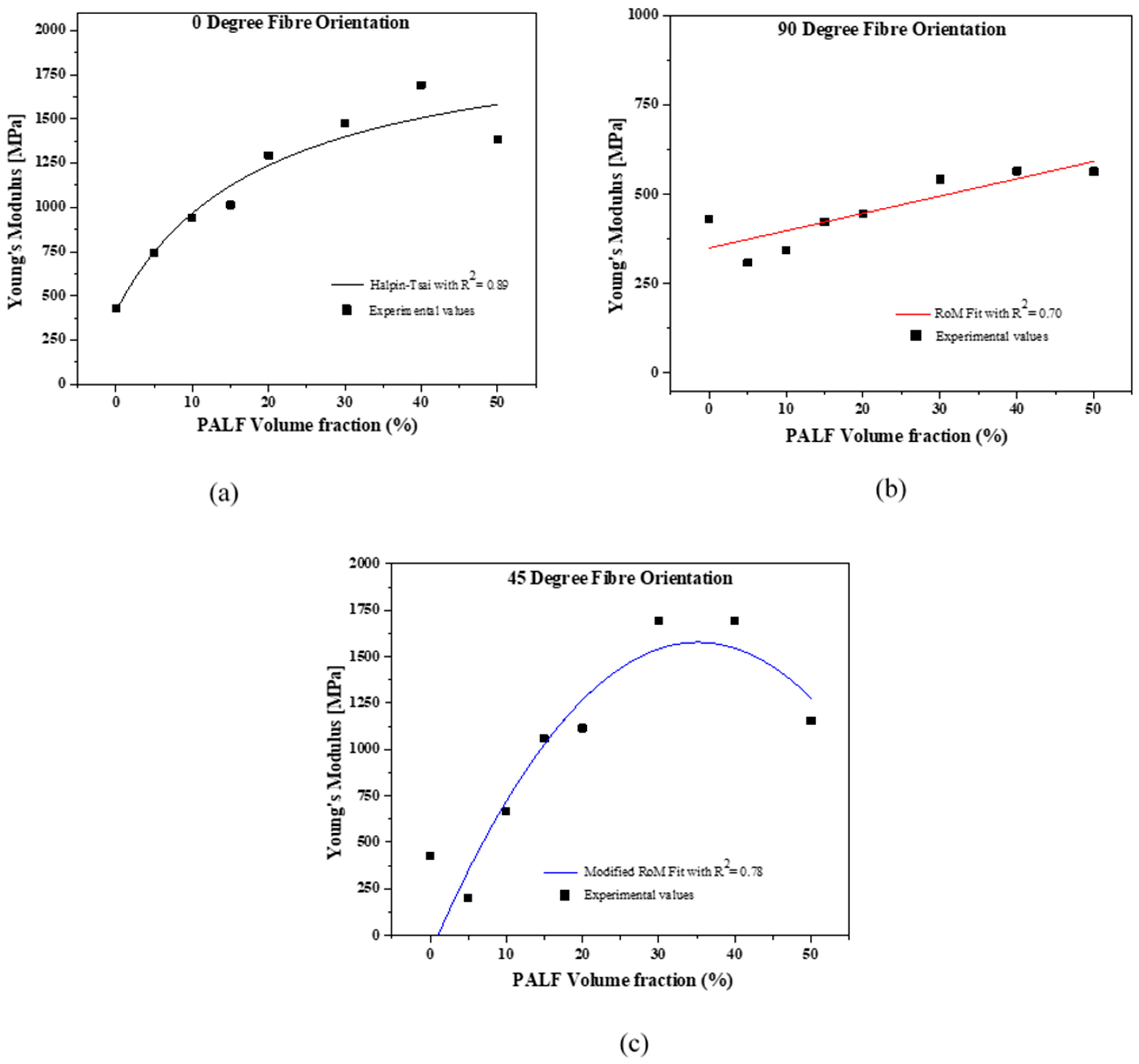
3.2. Micromechanical Model
3.3. Determining the Minimum, Critical and Maximum Fiber Volume for PALF/MMA Composites
4. Discussion
4.1. Effect of PALF Fiber Orientation and Volume Fraction on Flexural Properties of PALF/MMA Composite
4.2. Correlation between the Micromechanical Models and the Experimental Results
4.3. Maximum Practical Fiber Volume (νf.max) Relevant for PALF/MMA Composite Application
5. Conclusions
Author Contributions
Funding
Institutional Review Board Statement
Informed Consent Statement
Data Availability Statement
Acknowledgments
Conflicts of Interest
Abbreviations
| Acronym | Meaning |
| PALF | Pineapple leaf fiber |
| PS | Prosthetic Socket |
| MMA | Methyl methacrylate |
| FRC | Fiber Reinforced Composite |
| CS | Composite Strength |
| CFM | Composite flexural modulus |
| RoM | Rule of mixture |
| MRoM | Modified Rule of mixture |
| H-T | Halpin–Tsai |
| ν.min | Minimum fiber volume |
| ν.max | Maximum fiber volume |
| ν.crit | Critical fiber volume |
References
- Hsu, L.H.; Huang, G.F.; Lu, C.T.; Hong, D.Y.; Liu, S.H. The Development of a Rapid Prototyping Prosthetic Socket Coated with a Resin Layer for Transtibial Amputees. Prosthet. Orthot. Int. 2010, 34, 37–45. [Google Scholar] [CrossRef] [PubMed] [Green Version]
- Pirouzi, G.; Abu Osman, N.A.; Eshraghi, A.; Ali, S.; Gholizadeh, H.; Wan Abas, W.A.B. Review of the Socket Design and Interface Pressure Measurement for Transtibial Prosthesis. Sci. World J. 2014, 2014, 849073. [Google Scholar] [CrossRef] [PubMed] [Green Version]
- Selvam, P.S.; Sandhiya, M.; Chandrasekaran, K.; Rubella, D.H.; Karthikeyan, S. Prosthetics for Lower Limb Amputation. In Prosthetics and Orthotics; IntechOpen: London, UK, 2021. [Google Scholar]
- Rajtukova, V.; Hudak, R.; Zivcak, J.; Halfarova, P.; Kudrikova, R. Pressure Distribution in Transtibial Prostheses Socket and the Stump Interface. Procedia Eng. 2014, 96, 374–381. [Google Scholar] [CrossRef] [Green Version]
- Berry, D. Composite Materials for Orthotics and Prosthetics. Am. Orthot. Prosthet. 1987, 40, 35–43. [Google Scholar]
- Phillips, S.L.; Craelius, W. Material Properties of Selected Prosthetic Laminates. JPO J. Prosthet. Orthot. 2005, 17, 27–32. [Google Scholar] [CrossRef]
- Quintero-Quiroz, C.; Pérez, V.Z. Materials for Lower Limb Prosthetic and Orthotic Interfaces and Sockets: Evolution and Associated Skin Problems. Rev. La Fac. De Med. 2019, 67, 117–125. [Google Scholar] [CrossRef]
- Gerschutz, M.J.; Haynes, M.L.; Nixon, D.; Colvin, J.M. Strength Evaluation of Prosthetic Check Sockets, Copolymer Sockets, and Definitive Laminated Sockets. J. Rehabil. Res. Dev. 2012, 49, 405. [Google Scholar] [CrossRef]
- Harris, B. Engineering Composite Materials; Institute of Materials: London, UK, 1999. [Google Scholar]
- WHO; USAID; International Society of Prosthetics and Orthotics (ISPO). Standards for Prosthetics and Orthotics-Part 1; World Health Organization: Geneva, Switzerland, 2017; ISBN 978-92-4-151248-0. [Google Scholar]
- Koumoulos, E.P.; Trompeta, A.-F.; Santos, R.-M.; Martins, M.; dos Santos, C.M.; Iglesias, V.; Böhm, R.; Gong, G.; Chiminelli, A.; Verpoest, I.; et al. Research and Development in Carbon Fibers and Advanced High-Performance Composites Supply Chain in Europe: A Roadmap for Challenges and the Industrial Uptake. J. Compos. Sci. 2019, 3, 86. [Google Scholar] [CrossRef] [Green Version]
- Asim, M.; Abdan, K.; Jawaid, M.; Nasir, M.; Dashtizadeh, Z.; Ishak, M.R.; Hoque, M.E. A Review on Pineapple Leaves Fibre and Its Composites. Int. J. Polym. Sci. 2015, 2015, 950567. [Google Scholar] [CrossRef] [Green Version]
- Amor, N.; Noman, M.T.; Petru, M. Classification of Textile Polymer Composites: Recent Trends and Challenges. Polymers 2021, 13, 2592. [Google Scholar] [CrossRef]
- Kouhi, M.; Butan, S.; Li, Y.; Shakour, E.; Banu, M. Role of Chemically Functionalization of Bamboo Fibers on Polyethylene-Based Composite Performance: A Solution for Recycling. Polymers 2021, 13, 2564. [Google Scholar] [CrossRef]
- Belgacem, C.; Serra-Parareda, F.; Tarrés, Q.; Mutjé, P.; Delgado-Aguilar, M.; Boufi, S. Valorization of Date Palm Waste for Plastic Reinforcement: Macro and Micromechanics of Flexural Strength. Polymers 2021, 13, 1751. [Google Scholar] [CrossRef]
- Serrano-Garcia, W.; Jayathilaka, W.A.D.M.; Chinnappan, A.; Tran, T.Q.; Baskar, C.; Thomas, S.W.; Ramakrishna, S. Nanocomposites for Electronic Applications That Can Be Embedded for Textiles and Wearables. Sci. China Technol. Sci. 2019, 62, 895–902. [Google Scholar] [CrossRef]
- Tran, T.Q.; Lee, J.K.Y.; Chinnappan, A.; Jayathilaka, W.A.D.M.; Ji, D.; Kumar, V.V.; Ramakrishna, S. Strong, Lightweight, and Highly Conductive CNT/Au/Cu Wires from Sputtering and Electroplating Methods. J. Mater. Sci. Technol. 2020, 40, 99–106. [Google Scholar] [CrossRef]
- Ramamoorthy, S.K.; Skrifvars, M.; Persson, A. A Review of Natural Fibers Used in Biocomposites: Plant, Animal and Regenerated Cellulose Fibers. Polym. Rev. 2015, 55, 107–162. [Google Scholar] [CrossRef]
- Ramamoorthy, S.K.; Åkesson, D.; Rajan, R.; Periyasamy, A.P.; Skrifvars, M. Mechanical performance of biofibers and their corresponding composites. In Mechanical and Physical Testing of Biocomposites, Fibre-Reinforced Composites and Hybrid Composites; Elsevier: Amsterdam, The Netherlands, 2019; pp. 259–292. ISBN 978-0-08-102292-4. [Google Scholar]
- Gaba, E.W.; Asimeng, B.O.; Kaufmann, E.E.; Katu, S.K.; Foster, E.J.; Tiburu, E.K. Mechanical and Structural Characterization of Pineapple Leaf Fiber. Fibers 2021, 9, 51. [Google Scholar] [CrossRef]
- Ogeng’o, J.A.; Obimbo, M.M.; King’ori, J. Pattern of Limb Amputation in a Kenyan Rural Hospital. Int. Orthop. 2009, 33, 1449–1453. [Google Scholar] [CrossRef] [PubMed] [Green Version]
- Amoah, V.M.K.; Anokye, R.; Acheampong, E.; Dadson, H.R.; Osei, M.; Nadutey, A. The Experiences of People with Diabetes-Related Lower Limb Amputation at the Komfo Anokye Teaching Hospital (KATH) in Ghana. BMC Res. Notes 2018, 11, 66. [Google Scholar] [CrossRef] [Green Version]
- Herrera-Franco, P.J.; Valadez-González, A. A Study of the Mechanical Properties of Short Natural-Fiber Reinforced Composites. Compos. Part B Eng. 2005, 36, 597–608. [Google Scholar] [CrossRef]
- ASTM. Standard Test Methods for Flexural Properties of Unreinforced and Reinforced Plastics and Electrical Insulating Materials. 2017. Available online: https://www.astm.org/Standards/D790 (accessed on 27 August 2021).
- Buragohain, M.K. Micromechanics of a Lamina. In Composite Structures; Buragohain, M.K., Ed.; CRC Press: Boca Raton, FL, USA, 2017; pp. 79–132. ISBN 978-1-315-26805-7. [Google Scholar]
- Das, O.; Kim, N.K.; Bhattacharyya, D. The mechanics of biocomposites. In Biomedical Composites; Elsevier: Amsterdam, The Netherlands, 2017; pp. 375–411. ISBN 978-0-08-100752-5. [Google Scholar]
- Cordin, M.; Bechtold, T.; Pham, T. Effect of Fibre Orientation on the Mechanical Properties of Polypropylene–lyocell Composites. Cellulose 2018, 25, 7197–7210. [Google Scholar] [CrossRef] [Green Version]
- Heidari-Rarani, M.; Bashandeh-Khodaei-Naeini, K.; Mirkhalaf, S. Micromechanical Modeling of the Mechanical Behavior of Unidirectional Composites—A Comparative Study. J. Reinf. Plast. Compos. 2018, 37, 1051–1071. [Google Scholar] [CrossRef]
- Dvorak, G. Micromechanics of Composite Materials; Solid Mechanics and Its Applications; Springer: Dordrecht, The Netherlands, 2013; Volume 186, ISBN 978-94-007-4100-3. [Google Scholar]
- Shah, D.U.; Schubel, P.J.; Licence, P.; Clifford, M.J. Determining the Minimum, Critical and Maximum Fibre Content for Twisted Yarn Reinforced Plant Fibre Composites. Compos. Sci. Technol. 2012, 72, 1909–1917. [Google Scholar] [CrossRef] [Green Version]
- Asumani, O.M.L.; Reid, R.G.; Paskaramoorthy, R. The Effects of Alkali–silane Treatment on the Tensile and Flexural Properties of Short Fibre Non-Woven Kenaf Reinforced Polypropylene Composites. Compos. Part A Appl. Sci. Manuf. 2012, 43, 1431–1440. [Google Scholar] [CrossRef]
- Machado, J.S.; Knapic, S. Short term and long-term properties of natural fibre composites. In Advanced High Strength Natural Fibre Composites in Construction; Elsevier: Amsterdam, The Netherlands, 2017; pp. 447–458. ISBN 978-0-08-100411-1. [Google Scholar]
- Hine, P.; Parveen, B.; Brands, D.; Caton-Rose, F. Validation of the Modified Rule of Mixtures Using a Combination of Fibre Orientation and Fibre Length Measurements. Compos. Part A Appl. Sci. Manuf. 2014, 64, 70–78. [Google Scholar] [CrossRef]
- Hossain, R.M.; Islam, A.; Van Vuure, A.W.; Ignaas, V. Effect of Fiber Orientation on the Tensile Properties of Jute Epoxy Laminated Composite. J. Sci. Res. 2012, 5, 43–54. [Google Scholar] [CrossRef]
- Bagherpour, S. Fibre Reinforced Polyester Composites. In Polyester; Saleh, H.E.-D., Ed.; InTechOpen: London, UK, 2012; ISBN 978-953-51-0770-5. [Google Scholar]


| Mechanical Property | PALF |
|---|---|
| Density (g/cm3) | 1.53 |
| Diameter (μm) | 61 ± 0.025 |
| Tensile strength (MPa) | 1620 ± 150 |
| Young’s modulus (GPa) | 27 ± 0.9 |
| Strain at break (%) | 6.7 ± 0.5 |
| Concentration of alkali treatment of PALF (w/w) | 6% |
| Treatment time (h) | 1 |
| Fiber Volume Fractions (% v/v) | Flexural Strength (MPa) | Flexural Modulus (MPa) | Percentage Strain at Failure (%) | ||||||
|---|---|---|---|---|---|---|---|---|---|
| Mean ± SD | Mean ± SD | Mean ± SD | |||||||
| Fiber Orientation (°) | Fiber Orientation (°) | Fiber Orientation (°) | |||||||
| 0 | 45 | 90 | 0 | 45 | 90 | 0 | 45 | 90 | |
| 0 | 45.0 ± 3.6 a | 45.0 ± 3.6 a | 45.0 ± 3.6 a | 429.0 ± 34.3 a | 429.0 ± 34.3 a | 429.0 ± 34.3 a | 13 ± 1.3 a | 13 ± 1.3 a | 13 ± 1.3 a |
| 5 | 39.0 ± 2.4 b | 9.8 ± 1.1 b | 23.6 ± 1.5 b | 741.8 ± 81 b | 199.2 ± 12.0 b | 308.4 ± 33.9 b | 5.0 ± 0.5 c | 5.0 ± 0.2 b | 8.0 ± 0.9 b |
| 10 | 42.7 ± 6.0 a | 21.3 ± 2.3 c | 25.6 ± 0.2 b | 940.1 ± 103 c | 666.8 ± 40 c | 343.4 ± 37.8 c | 4.5 ± 0.9 c | 4.3 ± 0.9 c | 7.5 ± 0.3 b |
| 15 | 45.1± 10.1 a | 26.1 ± 5.1 d | 26.8 ± 1.8 c | 1013.8 ± 111 d | 1058.0 ± 63 d | 422.4 ± 46.5 d | 4.1 ± 0.8 c | 3.8 ± 0.8 c | 6.5 ± 0.6 c |
| 20 | 45.6 ± 7.2 a | 28.2 ± 2.5 d | 16.4 ± 0.5 d | 1294.3 ± 142 e | 1114.4 ± 67 e | 445.0 ± 49.0 e | 3.9 ± 0.7 c | 3.3 ± 0.3 c | 4.9 ± 0.1 d |
| 30 | 45.5 ± 5.3 a | 35.9 ± 3.2 e | 17.9 ± 3.8 d | 1473.5 ± 162 f | 1677.6 ± 186 f | 542.3 ± 59.7 f | 3.6 ± 0.9 c | 2.9 ± 0.9 d | 4.4 ± 0.1 d |
| 40 | 50.2 ± 4.9 a | 33.6 ± 2.5 e | 10.4 ± 1.1 e | 1692.0 ± 186 g | 1677.6 ± 101 f | 565.0 ± 62.1 g | 3.3 ± 0.2 d | 2.6 ± 0.6 d | 2.9 ± 0.4 e |
| 50 | 28.1 ± 2.5 c | 25.7 ± 4.0 d | 14.4 ± 3.0 d | 1382.4 ± 152 h | 1155.5 ± 69 f | 563.9 ± 62.0 g | 4.0 ± 0.5 c | 3.1 ± 0.3 d | 2.8 ± 0.6 e |
| Fiber Orientation (°) | νf.min (%) | νf.crit (%) | νf.max (%) |
|---|---|---|---|
| 0 | 5 | 20 | 40 |
| 45 | 5 | Not realized | 30 |
| 90 | 5 | Not realized | 15 |
Publisher’s Note: MDPI stays neutral with regard to jurisdictional claims in published maps and institutional affiliations. |
© 2021 by the authors. Licensee MDPI, Basel, Switzerland. This article is an open access article distributed under the terms and conditions of the Creative Commons Attribution (CC BY) license (https://creativecommons.org/licenses/by/4.0/).
Share and Cite
Gaba, E.W.; Asimeng, B.O.; Kaufmann, E.E.; Foster, E.J.; Tiburu, E.K. The Influence of Pineapple Leaf Fiber Orientation and Volume Fraction on Methyl Methacrylate-Based Polymer Matrix for Prosthetic Socket Application. Polymers 2021, 13, 3381. https://doi.org/10.3390/polym13193381
Gaba EW, Asimeng BO, Kaufmann EE, Foster EJ, Tiburu EK. The Influence of Pineapple Leaf Fiber Orientation and Volume Fraction on Methyl Methacrylate-Based Polymer Matrix for Prosthetic Socket Application. Polymers. 2021; 13(19):3381. https://doi.org/10.3390/polym13193381
Chicago/Turabian StyleGaba, Eric Worlawoe, Bernard O. Asimeng, Elsie Effah Kaufmann, E. Johan Foster, and Elvis K. Tiburu. 2021. "The Influence of Pineapple Leaf Fiber Orientation and Volume Fraction on Methyl Methacrylate-Based Polymer Matrix for Prosthetic Socket Application" Polymers 13, no. 19: 3381. https://doi.org/10.3390/polym13193381
APA StyleGaba, E. W., Asimeng, B. O., Kaufmann, E. E., Foster, E. J., & Tiburu, E. K. (2021). The Influence of Pineapple Leaf Fiber Orientation and Volume Fraction on Methyl Methacrylate-Based Polymer Matrix for Prosthetic Socket Application. Polymers, 13(19), 3381. https://doi.org/10.3390/polym13193381