Abstract
Colloidal photonic crystal (PC)-based anti-counterfeiting materials have been widely studied due to their inimitable structural colors and tunable photonic band gaps (PBGs) as well as their convenient identification methods. In this review, we summarize recent developments of colloidal PCs in the field of anti-counterfeiting from aspects of security strategies, design, and fabrication principles, and identification means. Firstly, an overview of the strategies for constructing PC anti-counterfeiting materials composed of variable color PC patterns, invisible PC prints, and several other PC anti-counterfeiting materials is presented. Then, the synthesis methods, working principles, security level, and specific identification means of these three types of PC materials are discussed in detail. Finally, the summary of strengths and challenges, as well as development prospects in the attractive research field, are presented.
1. Introduction
Photonic crystals (PCs) are a kind of artificial microstructure composed of periodic arrangements of materials with different dielectric constants [1,2,3]. Due to the periodic modulation of the dielectric constant, PCs exhibit photonic band gaps (PBGs) that can exclude the propagation of photons with a specific frequency range in a lattice [1,4,5]. When the energy of visible light is located in the PBG, the PCs show bright and iridescent reflected colors, which are well-known structural colors [6]. Based on their unique photonic band-gap properties and tunable structural colors, PCs have shown great application potential in developing optical waveguides, lasers, optical fibers [7,8,9,10,11,12], displays [13,14,15,16], sensors [17,18,19], and anti-counterfeiting materials [20,21,22,23]. When PCs are used as anti-counterfeiting materials, their stable and iridescent structural colors cannot be imitated by pigments or dyes [23]. Moreover, their distinctive reflection spectra are also useful for anti-counterfeiting [21,24,25]. Therefore, anti-counterfeiting materials based on PCs have attracted extensive attention in recent years.
In the past three decades, PCs have been prepared using various methods, such as mechanical drilling [26], layer-by-layer stacking technique [27], photolithography [28], and reactive ion beam etching [29]. The PCs prepared by these micro-fabricated approaches have precise structures but complex and time-consuming preparation processes. In addition, it is difficult to realize the band gap located in a visible light band for three-dimensional PCs fabricated by these methods [4]. Therefore, an alternative approach to overcome these limitations has been studied, which is to self-assemble colloidal nanoparticles into order colloidal PC structures. Common self-assembly methods include sedimentation [30], spray coating [31,32], spin-coating [33], electrodeposition [34], centrifugation [35], vertical deposition [36], and inkjet printing [6,16,37]. Compared to the micro-fabricated approach, the self-assembly approach is always simple and inexpensive [29]. Moreover, through careful selection of assembly methods and conditions, the colloidal PCs with different dimensions (1D, 2D, 3D) and geometry shapes (film, dots, lines, sphere, stars) can be easily realized [4,38]. These colloidal PCs show bright structural colors due to band gaps in the visible region [4]. Moreover, the structural colors and band gaps of colloidal crystals can be tuned by external stimuli, such as vapor [39,40], temperature [41], and electrical [42] and magnetic fields [23,43], which can be distinguished by the naked eye or spectrometers. These advantages of colloidal PC, such as sample preparation technology, easily tunable optical property, and flexible geometry structure, make it a more ideal candidate for anti-counterfeiting materials compared with micro-fabricated PC.
In this review, recent advances in colloidal PC materials for anti-counterfeiting purposes will be discussed from the aspects of security strategies, design and fabrication principles, and identification means. Firstly, we divide anti-counterfeiting colloidal PC materials into three categories: variable colored PC patterns, invisible PC prints, and a few other PC security materials, and discuss general strategies for creating these materials. Then, the synthesis methods, working principles, security level and specific identification means of these three kinds of colloidal PC materials are discussed in detail, respectively. Finally, a summary of anti-counterfeiting colloidal PC materials in terms of their opportunities and challenges is presented.
2. Strategies to Construct Anti-Counterfeiting Colloidal PC (ACPC) Materials
Most colloidal PCs can be used as anti-counterfeiting materials because of their tunable structural colors; however, a few are based on their other properties, such as fluorescence enhancement properties. According to this, we can divide colloidal PCs into two types: ACPC materials based on tunable structural colors and ACPC materials based on other properties. The strategies to construct the two types of ACPC materials are outlined below.
2.1. ACPC Materials Based on Tunable Structural Colors
ACPC materials based on tunable structural colors can be further classified into two types, visible ACPC patterns and invisible ACPC patterns, according to security strategies. A brief introduction to the strategies for constructing visible ACPC patterns and invisible ACPC patterns is presented in the following.
2.1.1. Principles for Constructing Visible ACPC Patterns
Visible colloidal PC patterns can be used for anti-counterfeiting purposes because their structural colors can be tuned. Therefore, it is necessary to briefly introduce the physical principles of the formation of structural colors in colloidal PCs.
Colloidal PCs are the spatially periodic structures assembled from colloidal nanoparticles, which can be divided into one-, two- or three-dimensional (1D, 2D, 3D) colloidal PCs according to their periodicity. The structural colors are originated from the diffraction of visible light from periodic microstructures. The diffraction properties can be described by Bragg’s law. For example, 1D PCs, namely Bragg stacks or Bragg reflectors, obey Bragg–Snell’s law and can be described by Equation (1) when incident light is perpendicular to the sample surface [44], where m is the order of diffraction, nl and nh represent the refractive indices of the low- and high-refractive-index components in the PC system, respectively, and dl and dh are the optical thicknesses of two components, respectively [4]:
The magnetically responsive PCs with chain-like structures are typical 1D colloidal PCs, and monolayer colloidal PCs are two-dimensional (2D) colloidal PCs [45]. The 3D colloidal PCs have opal structures and show bright structural colors due to diffraction of the 3D lattice [46]. The diffraction wavelength can be determined by Bragg–Snell’s law (Equation (2)), where m is the diffraction order, λ is the diffraction wavelength, neff is the effective refractive index of the system, θ is the incident angle, and d is the interplanar spacing [4]:
Since the colloidal particles usually self-assemble into (111) planes of face-centered cubic (FCC) lattices in the direction parallel to the sample surface, the diffraction wavelength can be also calculated using distance D between the center of the nearest spheres in (111) planes [46]. Thus, the Bragg law can be expressed by Equation (3) [47]. The effective refractive index neff can be expressed as Equation (4), where np and nm denote the refractive indices of particles and another medium, respectively, and Vp is the volume fraction of nanoparticles.
These equations provide guidance for the design of visible ACPC materials. In general, the changes in parameters of the equations that lead to the change in structural colors can be employed for constructing the visible ACPC materials, which can be summarized as follows:
- Changing the colloidal PC plane spacing is a good strategy for designing visible ACPC materials. Generally, when colloidal PCs are embedded into the polymers or the polymers with 3D inverse opal structures are formed, the expansion of the polymer under external stimulus will lead to the increase of distance between the nearest nanoparticles or pores, thereby changing their structural color. This color change is apparent to the naked eye and very useful for anti-counterfeiting.
- The change of the effective refractive index will lead to the change in the structural color. The absorption of new substances and the temperature-induced phase transition are two methods for changing the refractive index [4], where the former has been used to design visible ACPC materials. When the visible ACPC materials are composed of mesoporous nanoparticles, the hierarchical porous structure of particles is conducive to the absorption of gas molecules, thereby resulting in the change in the refractive index.
- Changing the incident angle can also cause a change in structural color. The majority of visible colloidal PC patterns utilized in the anti-counterfeit field are based on their angle-dependent structural colors. When the incident angle changes, the abundant color state transition of the patterns can be observed by the naked eye, which makes them high-level security materials.
- The transformation from disordered states to ordered states can also tune the structural color and can be applied in the field of anti-counterfeiting. A typical example here is magnetically responsive colloidal PC anti-counterfeit materials. In the absence of a magnetic field, the disordered superparamagnetic nanoparticles dispersed in solution show inherent chemical colors originating from light absorption, while these colloidal PCs exhibit bright structural colors under a magnetic field due to the ordered self-assembly of particles.
The above is a summary of the principles for constructing visible ACPC patterns. In the following section, preparation methods and working principles of different visible ACPC patterns designed using these four strategies will be discussed in detail.
2.1.2. Strategies to Create Invisible ACPC Patterns
Invisible photonic patterns are also known as invisible photonic prints. The patterns are invisible under normal circumstances and can only be displayed by applying corresponding an external stimulus [48], which makes them very useful for anti-counterfeiting. The key to constructing an invisible photonic print is to create the “pattern” and “background” with the same color and reflected wavelength (Δλ0 = 0) at a normal state, but a different color and reflected wavelength (Δλ ≠ 0) under the corresponding external stimulus [48,49,50]. In other words, the pattern and background must have very similar structures but different abilities to respond to the external stimulus, such as an electric field [14], magnetic field [50], deformation [48,51], or chemical stimuli [49,52]. According to this, many strategies to prepare invisible photonic prints have been proposed, which can be classified into four categories:
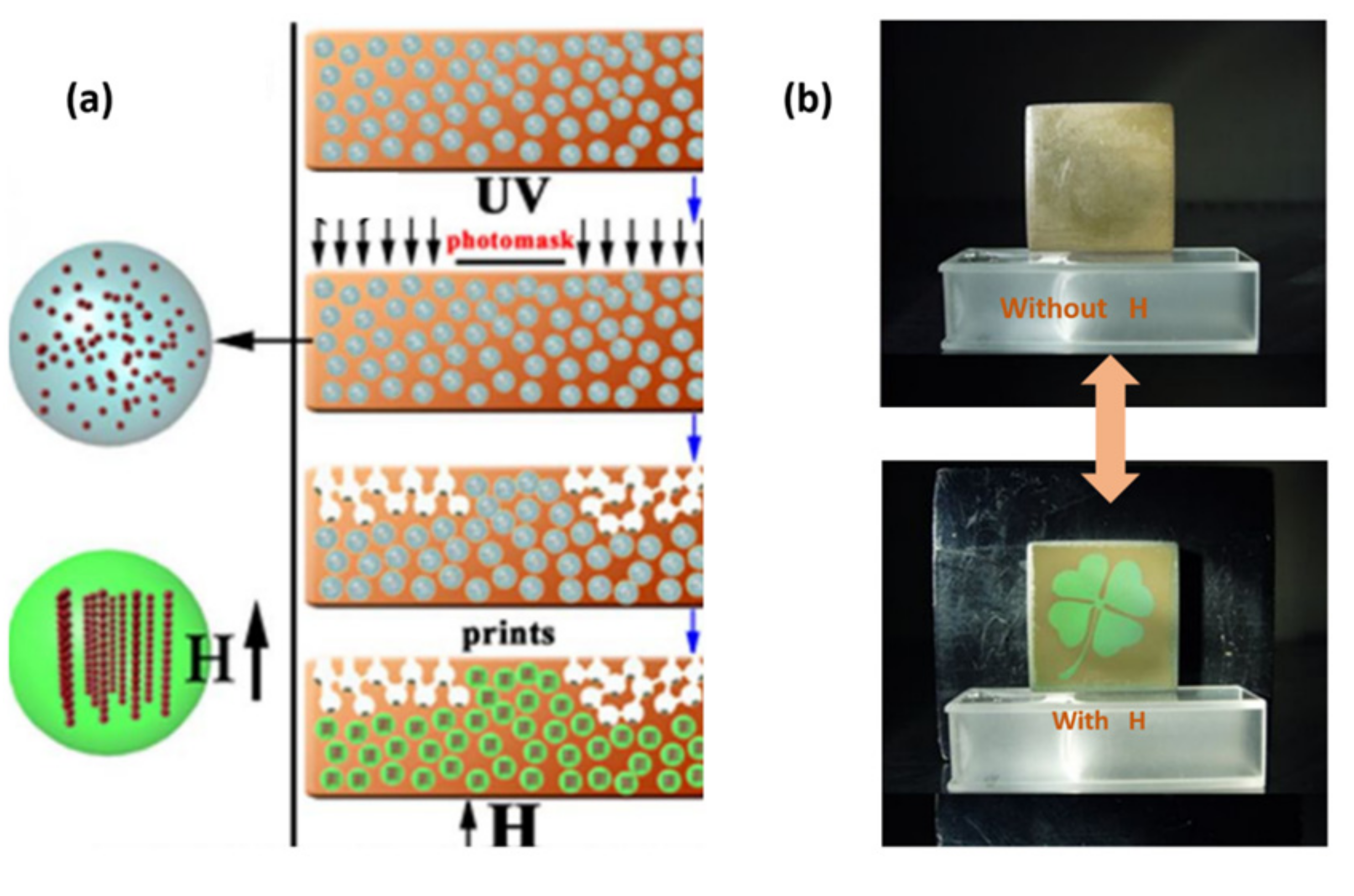
- Selective immobilization is the most widely used method to prepare invisible prints that can be shown by a magnetic field or applied stress. For the invisible print displayed in a magnetic field, in the initial state, the superparamagnetic particles are randomly dispersed into a photocurable polymer to form a stable colloidal suspension, which displays a uniform brown color derived from the selective absorption of light by particles. By using selective ultraviolet (UV) irradiation of the suspension through a hollow patterned mask, the superparamagnetic particles are fixed into the polymer matrix in the irradiated region (background region), while the particles can move freely in the non-irradiated region (pattern region). When the external magnetic field is absent, both pattern and background regions show uniform brown colors, thereby hiding the pattern. After applying the external magnetic field, the background region maintains the brown color because of the fixation of superparamagnetic particles, while the pattern region shows a bright structural color because of the self-assembly of superparamagnetic particles. The color contrast makes the pattern visible. In addition to UV curing, selective drying of the solvent in the magnetically responsive PC can be also considered as another selective immobilization method, which is because the particles are fixed after the solvent is completely removed. The reason for hiding and displaying patterns is similar to the former pattern fabricated by selective UV irradiation. As for invisible prints shown by deformation, only the pattern region is cross-linked due to the selective UV exposure. The cross-linked region and non-cross-linked region have similar color and different elasticity under the normal state, which makes different changes in lattice constants when applying the external force, thereby further leading to the color contrast between the pattern and background, and the appearance of the pattern.
- Selective modification is a simple and straightforward way of obtaining the pattern and background with different properties. Selective hydrophobic and hydrophilic modifications are common selective modification methods. The former approach is usually applied to the system in which colloidal PCs are embedded in hydrophilic polymers, where only the background region is modified by hydrophobic treatment. Thereby, the patterns on the prints are invisible in a dry state due to the similar structure and same color between pattern and background, while they can be shown by soaking in water, because the different water-absorbing swelling behaviors of the hydrophilic and hydrophobic regions result in a different lattice expansion and a large color contrast between them.
- Using nanoparticles of the same intrinsic color but different sizes to prepare invisible prints is also a good method, especially for an invisible print shown under a magnetic field. The pattern is invisible at a normal state because of the uniform inherent color of the superparamagnetic particles. The pattern can be revealed under a magnetic field because self-assembly of superparamagnetic particles with different sizes leads to the structural color contrast between pattern and background.
- In some cases, the patterned substrate will disturb the self-assembly of colloidal particles. Therefore, the introduction of the patterned substrate into the PC system can enable the formation of an invisible print. For example, the invisible print based on electrically responsive PCs has been successfully prepared in this way, where the substrate electrode was patterned by covering with an insulating polymer film. The pattern is invisible under normal circumstances due to the uniform color originating from the suspension of charged composite microspheres. The pattern can be displayed under the electric field because the pattern displays the original color derived from a random arrangement of charged microspheres, while the background showed the structural color.
In the following section, the working mechanisms, tuning methods and relative merits of invisible ACPC patterns created by these methods will be discussed in detail.
2.2. ACPC Materials Based on Their Other Properties
Almost all PC materials used for anti-counterfeiting are based on their tunable structural colors that originate from Bragg diffraction. In addition to the tunable structural colors, other important optical properties of PCs are also useful in the security field, including unique reflectivity properties and fluorescence enhancement effects. Based on these two properties, Song and co-workers designed a novel ACPC material composed of PC dots with three shapes, which were obtained by printing colloidal particles onto poly(dimethylsiloxane) (PDMS) substrates with different rheology states via an ink-jet printing method [53]. Due to the large optical differences in reflectivity property, and fluorescence enhancement of the three differently shaped PC dots, the ACPC material can show different images according to different optical conditions.
Tunable structural color generally means that the diffraction wavelength or PBG can be tuned by lattice parameters. In addition to tunable color, tunable diffraction intensity is also very useful for anti-counterfeiting. For example, Nam et al. [54] reported a monolayered PC anti-counterfeiting pattern fabricated by an inkjet-printing method, where the PC consisted of silica particles with a refractive index of 1.45 and voids with a refractive index of 1.0. The PC pattern showed an extremely weak structural color because the inkjet-printed colloidal PC possessed a short-range ordered structure and the monolayered structure further reduced the diffraction intensity of the PC [37]. This pattern was barely visible on a white background in daylight, while it became obvious by applying an external light source or changing the background. This is because the enhancement of diffraction color can be achieved by absorbing stray light through a black background or increasing the intensity of incident light.
Based on a similar security strategy, Shang et al. [55] further fabricated an anti-counterfeiting PC film by firstly constructing the magnetically responsive PC pattern and then fixing the PC pattern under a magnetic field, where the pattern was prepared by selective photo-polymerization of a photocurable colloidal suspension containing Fe3O4@C nanoparticles and a photocurable resin through a patterned mask. In the non-patterned region that was not protected by a mask, the monomer cross-links to form a polymer network and Fe3O4@C particles were steadily fixed into the network with a random arrangement, so that the non-patterned region lost its responsive ability to external magnetic fields and showed a constant brown color. In contrast, the suspension containing Fe3O4@C particles in the patterned region protected by a mask showed the structural color when a magnetic field was applied. Due to strong light scattering in the PC pattern, the pattern showed a very weak color and low diffraction intensity. The small color contrast between the patterned and non-patterned region makes it invisible when it was placed on a white background, while it was visible on a black background, because the black background can reduce array scattering and increase the signal-to-noise ratio [54].
These ACPC materials can easily realize the transition from invisible to visible state by changing light conditions or backgrounds without changing the intrinsic structure, which endows them with good durability and good usability.
3. Visible Colloidal PC Patterns for Anti-Counterfeiting
A visible colloidal PC anti-counterfeiting pattern is one that can alter the structural color when the incident angles or viewing angles change or external stimuli are applied, and remains in a visible state even in the absence of stimulations. The structural color can be tuned by angles that originate from the inherent PBG property of the PC, while tuning by the external stimulus is due to the introduction of a responsive PC. Common external stimuli include the magnetic field, temperature field, and chemical stimulus, which lead to changes of lattice parameters in the PC structure, such as the angle of incidence, the lattice constant, refractive index, and order of the photonic structure, thereby changing the structural color of the PC pattern. The color state transition can be easily observed by the naked eye, which means it has great application potential in the field of anti-counterfeiting.
3.1. Visible Single-Colored PC Patterns Based on Their Angle-Dependent Structural Colors for Anti-Counterfeiting
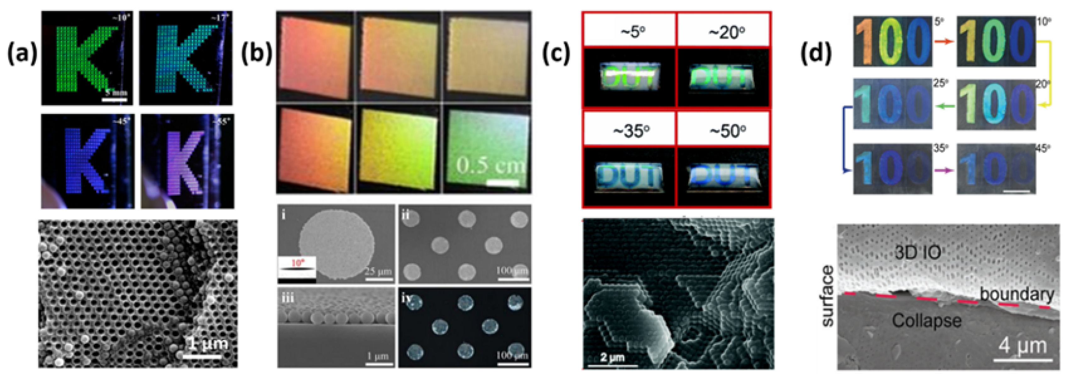
Most visible PC patterns utilized in the security field are based on their angle-dependent structural colors. Since the typical example was reported by Yang’s group [20], a lot of PC security patterns have been developed, which have the same security strategy but different structures. Typical PC structures include non-close-packed and close-packed FCC structures and inverse opal (I-opal) structures. For example, Yang’s group reported a security material that was composed of a SiO2 colloidal PC with a non-close-packed FCC structure embedded into a photocurable ethoxylated trimethylolpropane triacrylate (ETPTA) matrix. The PC film can be easily patterned by using conventional photolithography techniques. The patterned PC film showed a very bright structural color and had four-color states transition when viewing angles changed between 0° and 55° (Figure 1a), which can be attributed to the low refractive index contrast between silica (n = 1.45) and ETPTA (n = 1.4689) [20].

Figure 1.
Colloidal photonic crystal (PC) patterns with different structures based on their angular-dependent structural colors for anti-counterfeiting. (a) Anti-counterfeiting colloidal PC (ACPC) patterns with non-close-packed FCC structure. Reused with permission from Reference [20], Copyright 2013, American Chemical Society. (b) ACPC patterns composed of mono-layered closest-packed nanoparticles. Reused with permission from Reference [54], Copyright 2016, Springer Nature. (c) ACPC patterns with close-packed FCC structures. Reused with permission from Reference [56], Copyright 2018, The Royal Society of Chemistry. (d) ACPC patterns with inverse opal structures. Reused with permission from Reference [22], Copyright 2018, Wiley-VCH.
The colloidal PC with close-packed FCC structure can be further divided into two types. One is only composed of colloidal nanoparticles with the closest packing. The typical example is an inkjet-printed colloidal PC, where colloidal nanoparticles are printed onto substrates and can arrange into highly ordered FCC arrays under the evaporation-driven self-assembly process. For example, Nam et al. [54] reported an ACPC pattern which was prepared via inkjet-printing method, which consisted of mono-layered closest-packed nanoparticles. The PC pattern can change its color as the viewing angle changes (Figure 1b). Wu and co-workers also reported an inkjet-printed PC pattern composed of CdS particles that also had a close-packed structure [37]. The PC pattern showed a bright structural color when the viewing angle was relatively close to the incident angle, which was due to a relatively large refractive index contrast between CdS particles (n = 2.5) and the air voids (n = 1). Moreover, the structural color can change at different viewing angles, which is useful for security purposes. It is also should be noted that PC patterns can display a uniform yellow color resulting from the inherent color of the CdS microspheres when the viewing angle is away from the incident angle. Therefore, the pattern can realize the conversion from visible to invisible states under varied viewing angles by using monodispersed CdS nanoparticles with different sizes to construct the pattern and background, respectively, which further improves the security level of this pattern.
The other type is a composite PC material formed by filling a polymer into the interstitial space of the FCC close-packed structure. Wu’s group reported an ACPC material in which the uniform polystyrene (PS) particles self-assembled into a close-packed FCC lattice embed into the PDMS polymer matrix [56]. The anti-counterfeiting PC pattern fabricated by a spraying method showed different structural colors at different angles (Figure 1c). It is also worth mentioning that sandwiching an anti-counterfeiting pattern between two layers of PDMS can ensure its durability.
I-opal structure is also a common 3D PC structure formed by first permeating the polymers or gels into the interstitial space of an opal structure to form the composite PC structure and then removing the opal template via chemical methods. The I-opal structure always possesses low mechanical strength, thereby affecting its durability in the anti-forgery field. However, recently, Meng and coworkers reported a robust anti-counterfeiting patterned polyvinylidene fluoride (PVDF) film with I-opal structure, where the good durability of the pattern was due to intrinsically excellent mechanical properties of PVDF resin [22]. The patterned film obtained by the pressing method had a typical well-ordered I-opal structure, thereby producing the structural color with strong angle-dependency. Thus, six distinct color states transition of patterned PVDF film can be observed when viewing angles changed (Figure 1d), which makes it a good security material.
3.2. Visible ACPC Patterns Based on Magnetically Responsive PCs
3.2.1. Visible Magnetically Responsive PC Security Patterns Based on the Transition from Disorder to Order
Magnetically responsive PCs have been prepared by self-assembly of uniform colloidal superparamagnetic nanoparticles, where the nanoparticles are composed of tiny magnetite (Fe3O4) nanocrystals with an average size less than 10 nm [57]. The structures of magnetic-responsive PCs include 1D chain-like structures, 2D sheets, and 3D crystal structures, where the dimensionality of the ordered structure mainly depends on the nanoparticle concentration [58]. Magnetically responsive structures have attracted much attention in the field of anti-counterfeiting in recent years because they can achieve an instantaneous transition between assembled and disassembled states when applying or removing an external magnetic field, where the assembled and disassembled states respectively show a bright structural color and a brown color. The color contrast can be easily observed by the naked eye.
Hu et al. [23] developed a simple and cost-effective method to fabricate PC security materials based on magnetically induced self-assembly of superparamagnetic nanoparticle technology. They were patterned by firstly making letter-shaped cavities and then infiltrating the suspension containing magnetic particles into the cavities (Figure 2a). In these letter patterns, some contained carbon-capped superparamagnetic nanoparticles (Fe3O4@C) with uniform size, while others contained nanoparticles with two different sizes. All letters showed uniform pale brown colors in the absence of the magnetic field, while patterns showed bright structural colors under the magnetic field because of the formation of 1D chain-like PC structures parallel to the direction of the magnetic field (Figure 2b,c). It should be noted that the PCs containing the nanoparticles with two different sizes had double PBG heterostructures and displayed uniform structural colors (Figure 2b) due to the additive effect of monochrome. This large color contrast before and after applying magnetic fields can be easily identified by the naked eye, and special double diffraction peaks can be detected with a fiber optic spectrometer, which makes it difficult to be mimicked by conventional dyes and pigments.
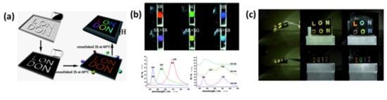
Figure 2.
Visible magnetic-responsive Photonic crystals (PC) patterns for anti-counterfeiting based on the transition from disorder to order. (a) Schematic illustrations for fabricating anti-counterfeiting PC patterns. (b) Magnetic-responsive PC patterns containing uniform nanoparticles with one or two sizes had one or two photonic band gaps (PBGs), respectively, but displayed single colors. (c) The large color contrast of PC patterns appeared when applying the external magnetic field. Reused with permission from Reference [23], Copyright 2012, The Royal Society of Chemistry.
Another security material based on magnetic-responsive PCs was also reported by Hu’s group, which was composed of uniform Fe3O4@C superparamagnetic nanoparticles in ethylene glycol (EG) emulsion droplets distributed in a cured resin matrix [59]. This lithography produced security pattern could realize a large color contrast when applying or removing a magnetic field, where the reason for the color change was the same as above. This pattern had a 1D chain-like structure and can be used as an anti-counterfeiting watermark on banknotes because of its flexibility, translucency, and ultra-thinness.
3.2.2. Visible Magnetic-Responsive PC Security Patterns Based on Their Photonic Bandgap and Birefringence Properties
In previous reports, magnetic-responsive PC security patterns always had 1D chain-like structures composed of spherical silica particles, which is because this type of PC had a lower volume fraction of superparamagnetic nanoparticles, so that they could easily realize instantaneous switching between ordered and completely disordered states [60].
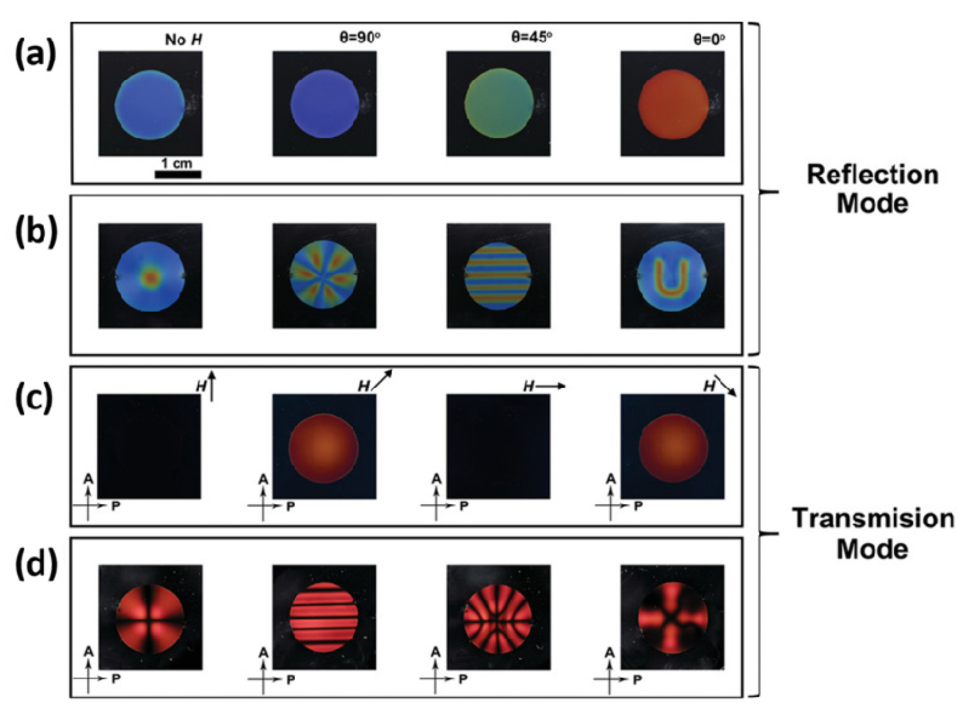
Recently, Li and coworkers reported an anti-counterfeiting device based on a 3D colloidal PC structure self-assembled from uniform Fe3O4@SiO2 nanorods in concentrated suspension [61]. Differently from the previously reported magnetic-responsive PC with 1D chain-like structures, these Fe3O4@SiO2 nanorods could also form an ordered polycrystalline structure without an external magnetic field because the particle content was over the critical concentration in the suspension. Therefore, it showed a structural color instead of a uniform brown color even in the absence of a magnetic field. When applying a vertical magnetic field, the nanorods self-assembled into a 3D monoclinic crystal structure instead of a polycrystalline structure and showed a uniform structural color. In addition to the distinct structural color, the PC also had other important optical properties, namely, the optical birefringence property produced by the shape anisotropy of the nanorods. The anti-counterfeiting device based on a unique structural color and the birefringence property was prepared by sandwiching this colloidal PC containing spontaneously arranged nanorods between two cross polarizers. When the device was exposed to daylight or other external light sources, it worked in reflection mode and showed its bright structural color. The structural color of the device can be easily changed when applying a magnetic field or rotating the magnet (Figure 3a). Moreover, controlling the field distribution can realize the display of different patterns on the device due to the large color contrast between two regions with and without an external magnetic field (Figure 3b). In addition to reflection mode, it can also work in transmission mode when it is under the illumination of the backlight. In this mode, the device can achieve a transition between dark and bright states by changing the direction of the magnetic field in the horizontal plane (Figure 3c). Moreover, the device shows different patterns when applying different shaped magnets, which is caused by the large brightness contrast between two regions under magnetic fields with different directions (Figure 3d). These rapid and reversible transitions, including color states, light and dark states, and pattern shapes, can be easily recognized by the naked eye, thereby making it a higher-level security material compared to anti-fake materials based on the transition in color states [61].
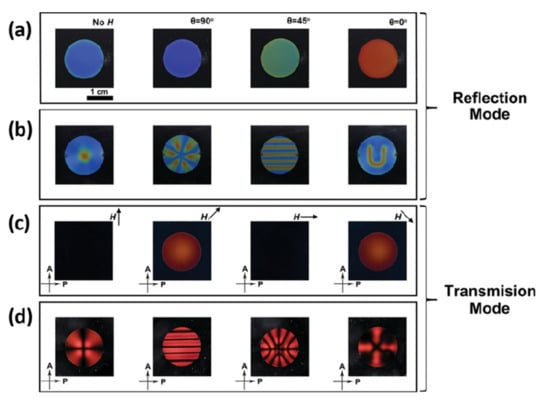
Figure 3.
Magnetic-responsive PC patterns based on their photonic band-gap and birefringence properties for anti-counterfeiting. (a) Digital photos showing that the structural color of the anti-counterfeiting device based on magnetic-responsive PC strongly depends on the magnetic field and the direction of the magnetic field. (b) Digital photos of the anti-counterfeiting device showing different patterns under different non-uniform magnetic fields. (c) The transition between dark and bright states through changing the direction of the magnetic field in the horizontal plane. (d) The device showing different patterns when applying a different non-uniform magnetic field. Reused with permission from Reference [61], Copyright 2019, Wiley-VCH.
3.3. Visible Thermoresponsive PC Security Patterns Based on the Change in Lattice Spacing
Poly(N-isopropyl acrylamide) (PNIPAM) is a temperature-sensitive polymer that has a low volume phase transition temperature of about 32 °C. When the temperature increases, the PNIPAM gel will shrink, so that integrating a temperature-sensitive PNIPAM gel into PC systems is a good strategy to prepare thermoresponsive PCs. For example, Asher et al. [62] successfully fabricated a thermoresponsive PC material [62] by embedding the colloidal PC structure into a temperature-sensitive PNIPAM gel matrix [41], where the diffraction wavelength of this thermoresponsive PC can be tuned between 704 and 460 nm when the temperature was switched between 10 and 35 °C [62]. In addition to the composite PC structure, an ordered porous PNIPAM gel with an I-opal structure can also achieve a sharp and reversible response to temperature by removing the colloidal PC framework, which has been reported by Takeoka and Watanabe et al. [63,64].
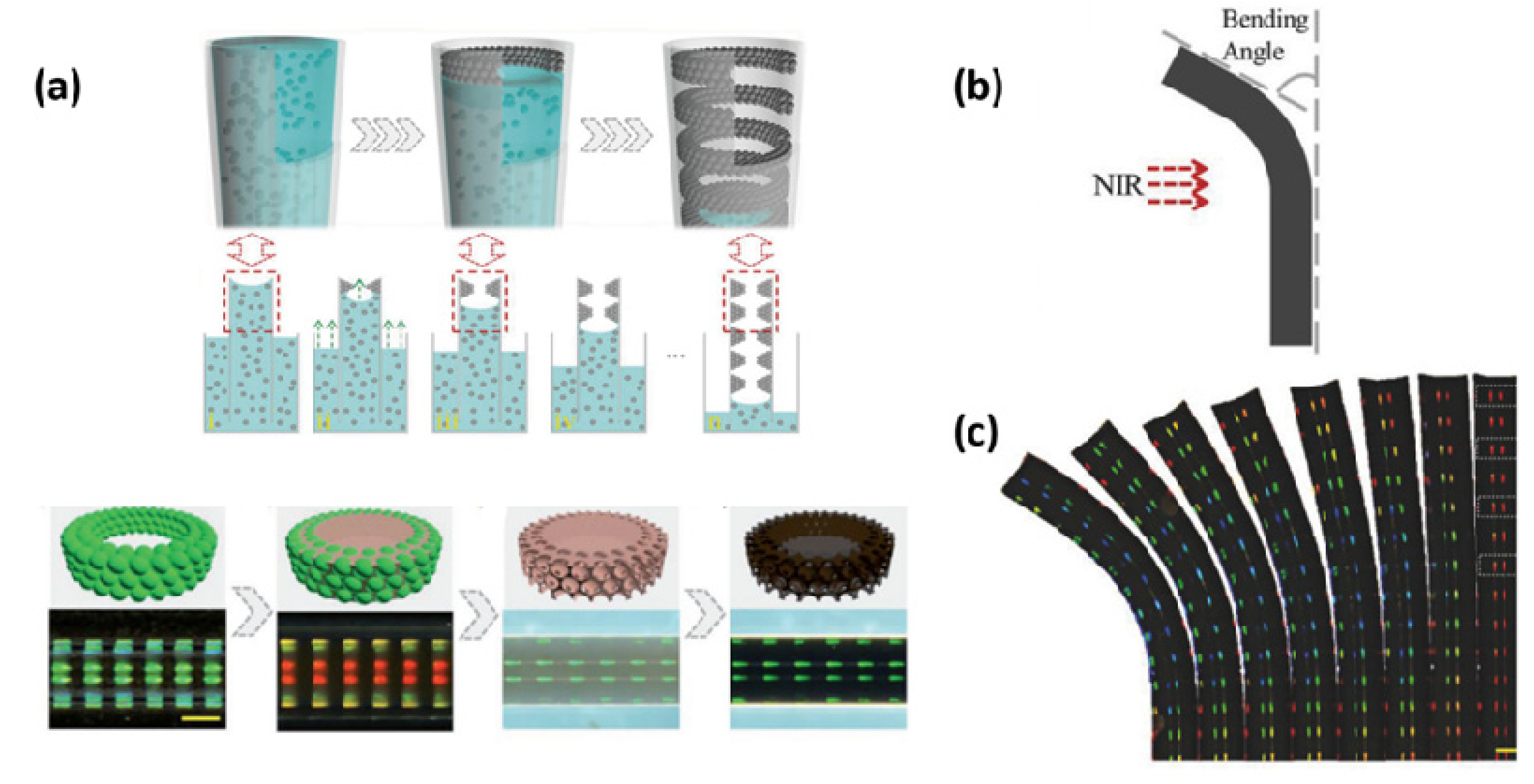
Based on the thermoresponsive PC material, Zhao’s group developed a near-infrared (NIR) light-responsive striped hydrogel fiber with an I-opal structure for anti-counterfeiting, which was composed of thermoresponsive PNIPAM and NIR light-sensitive reduced graphene oxide (rGO) [65]. The stripe-patterned PNIPAM/rGO fiber can be obtained by firstly fabricating the stripe-patterned colloidal PC on the inner surface of a capillary tube, then permeating hydrogel solutions consisting of NIPAM monomers, cross-linkers, initiators, and graphene oxide into the interstices of a striped colloidal PC and completely solidifying the solution mixtures, and finally etching the silica colloidal PC arrays and the glass capillary by HF solution (Figure 4a). It is also worth mentioning that the formation of a stripe-patterned colloidal PC instead of a homogeneous colloidal PC is caused by a lower colloid concentration of the suspension. Moreover, the width, spacing, and color of the striped pattern can be precisely controlled by adjusting the concentration of suspension and the self-assembly parameters. In the PNIPAM/rGO composite fiber, rGO had strong infrared absorption properties, high photothermal conversion efficiency, and high thermal conductivity, so that PNIPAM absorbed heat and displayed shrinking behavior when exposed to NIR light, leading to the change in lattice spacing and reflected color. Because the NIR light was only irradiated from one side of the fiber and irradiation was concentrated in the middle of the sample, the fiber showed inconsistent shrinking behavior (Figure 4b), resulting in an uneven change in lattice spacing. This further led to different degrees of bending behavior and different blue-shift values in different stripes of the fiber (Figure 4c), which can be easily observed by the naked eye. These properties have not been reported by previous materials with tunable structural colors, thereby making the material ideal for use in anti-counterfeit barcodes.
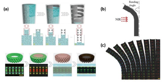
Figure 4.
Thermo-responsive PC patterns based on the change in lattice spacing for anti-counterfeiting. (a) Formation of a near-infrared (NIR) light-responsive striped Poly(N-isopropyl acrylamide)/ reduced graphene oxide (PNIPAM/rGO) fiber with I-opal structure. (b) PNIPAM/rGO fiber bending toward the direction of light. (c) A group of digital photos showing that the fiber has a varying colored striped pattern at different bending angles. Reused with permission from Reference [65], Copyright 2017, Wiley-VCH.
3.4. Visible Vapor Responsive PC Security Patterns Based on the Change in Refractive Index
In addition to introducing responsive materials or changing the incident angle of the light source, changing the effective refractive index is also a common way to tune the structural colors in PC systems, where the change of refractive index can be achieved through infiltrating chemical vapors and solvents into the porous PC structures.
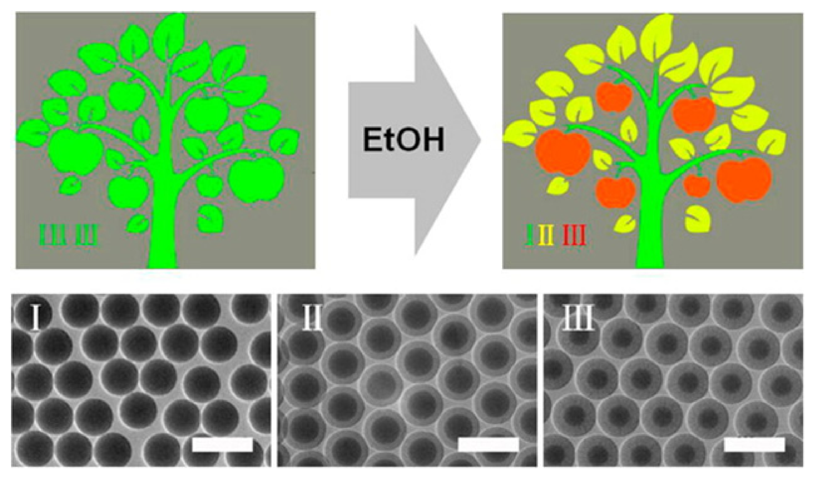
Bai and coworkers reported a security pattern based on vapor-responsive PCs, where the PCs were formed by self-assembly of mesoporous silica nanoparticles composed of SiO2 solid cores and mesoporous shells [39]. The vapor-responsive PCs possessed special hierarchical porous structures so that the vapor could be adsorbed on the structures, leading to the increase of the mean refractive index and change of structural color. It is worth mentioning that the mean refractive index of the mesoporous PC depends on the respective refractive index and volume rate of the SiO2 solid core, SiO2 in the shells, mesopores in the shells, and the void spaces between the order colloidal arrays. In fact, when the PC was exposed to different vapor conditions, only the refractive index of the mesopores changed, and the refractive index of the void spaces remained the same. Therefore, when PCs are composed of solid silica particles, they can hardly change their colors because of no response to vapor. Furthermore, the color response ranges of the vapor-responsive PCs can be adjusted through controlling the core and shell thicknesses. This security pattern was created by integrating three types of PCs with different vapor-responsive capacities into a whole via an inkjet-printing method. As shown in Figure 5, the anti-counterfeiting tree pattern was composed of tree trunks, tree leaves and fruit, respectively formed by self-assembly of solid silica particles, and mesoporous silica particles with different core and shell thicknesses, where the trunk, leaf, and fruit images were composed of PCs with very close structures but different responses to vapor. Therefore, the tree pattern showed a uniform green color under an N2 atmosphere, while in ethanol (EtOH) vapor, the tree trunk still displayed the green color, and the tree leaves and fruit turned a yellow and red color, respectively. This multicolored pattern can be easily revealed by non-toxic ethanol vapor and recognized by the naked eye, so is favorable for anti-counterfeiting.

Figure 5.
The structural color of the inkjet-printed tree pattern under N2 and saturated EtOH atmospheres, where a pattern composed of tree trunks, tree leaves and fruit, respectively, is formed by self-assembly of solid silica particles, and mesoporous silica particles with different core and shell thicknesses. Reused with permission from Reference [39], Copyright 2014, American Chemical Society.
4. Invisible Colloidal PC Prints for Anti-Counterfeiting
The invisible photonic print consists of the pattern that was hidden under normal circumstances but revealed under a specific stimulus (e.g., chemical or mechanical stimulus, and electrical or magnetic field stimulus). That transition between invisible state and visible state is instantaneous, reversible and easily recognizable to the naked eye, which makes it well-suited for an anti-counterfeiting device. To build invisible photonic prints, two kinds of PCs with the same color but different response capability to external stimuli need to be integrated into a print, where the integration strategies include selective immobilization, cross-linking and modification of prints, and selective modification of substrates and self-assembly of nanoparticles with different sizes. A good invisible photonic print for anti-counterfeiting is usually characterized by a simple and nontoxic identification method, good reversibility, fast decryption speed, good stability, and durability.
4.1. Invisible Colloidal PC Patterns Shown by Chemical Stimulus
4.1.1. Invisible Colloidal PC Patterns Shown by Water Fabricated by Selective Modification or Selective Cross-Linking
Invisible colloidal PC patterns shown by water have been fabricated by selectively cross-linking or modifying the water-responsive PC films, where the classic system of water-responsive PCs was constructed by introducing the water-swellable polymers into periodic colloidal PC structures.
For example, Ge’s group reported an invisible photonic print displayed by soaking in water, which was prepared by permeating NaOH solution or 3-aminopropyl-trimethoxysilane (APS) solution into the unshielded region (background region) on a pre-made PC film composed of a chain-like colloidal PC structure embedded in a polymer matrix [52], where the pre-made PC film was composed of Fe3O4@SiO2 colloids and the polymer matrix formed by the cross-link of three monomers (poly(ethylene glycol) diacrylate, poly(ethylene glycol) methacrylate, and 3-trimethoxysilyl-propyl-methacrylate). The NaOH or APS solution can further cross-link the polymer matrix in the background region, which makes the background region display higher levels of cross-linking than the pattern region protected by the mask. The cross-linking process rarely changed the structure of the PC, so that pattern and background regions have a low diffraction wavelength contrast, resulting in the hiding of the photonic print. Because a different cross-linking degree leads to a different swelling speed of the pattern and background, the pattern will be easily shown by soaking in water (Figure 6a). The print has good reversibility but slower decryption speed (about several minutes).
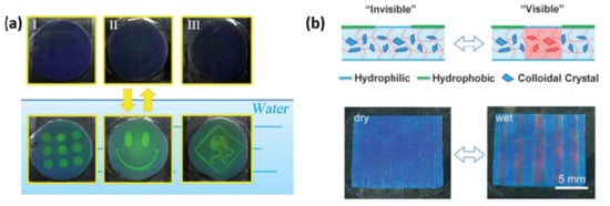
Figure 6.
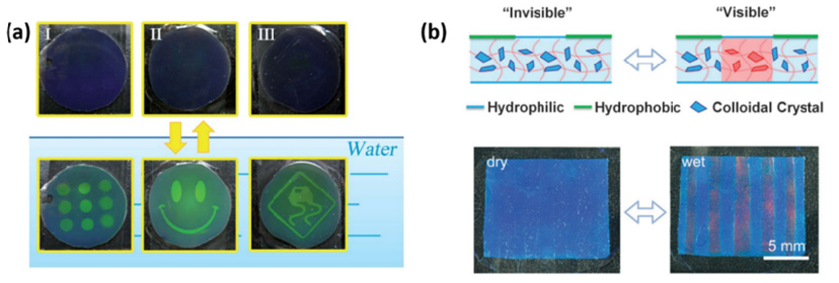
Invisible colloidal PC patterns shown by water. (a) The invisible prints prepared by selective cross-linking method revealed by soaking in water for 5 min. Reused with permission from Reference [52], Copyright 2012, The Royal Society of Chemistry. (b) The invisible print prepared by selective hydrophobic modification revealed by soaking in water within 10 s. Reused with permission from Reference [49], Copyright 2015, The Royal Society of Chemistry.
Based on similar design strategies, this group further fabricated an invisible colloidal PC pattern shown by water with a fast display speed [49]. In this case, the invisible print can be obtained by filling fluoroalkylsilane vapor into the unshielded background region on the hydrophilic PC film, where the PC consisted of a SiO2 colloidal crystal framework embedded into a poly(ethylene glycol) methacrylate (PEGMA) matrix, and the refractive indices of the two components were 1.45 and 1.46, respectively. This process of selective modification made the unshielded background region hydrophobic, while the shielded pattern region remained hydrophilic. Generally, the pattern was invisible under normal circumstances because the modification process hardly changed the lattice constant. When it was soaked in water, the pattern could appear within 10 s (Figure 6b). Its decryption speed was much faster than the former invisible photonic print shown by water, because the uncross-linked characteristic gave it superior swelling ability. The pattern could achieve reversible transformation between visible and invisible states by soaking in water or evaporating the water.
4.1.2. Invisible Colloidal PC Patterns Shown by Vapor
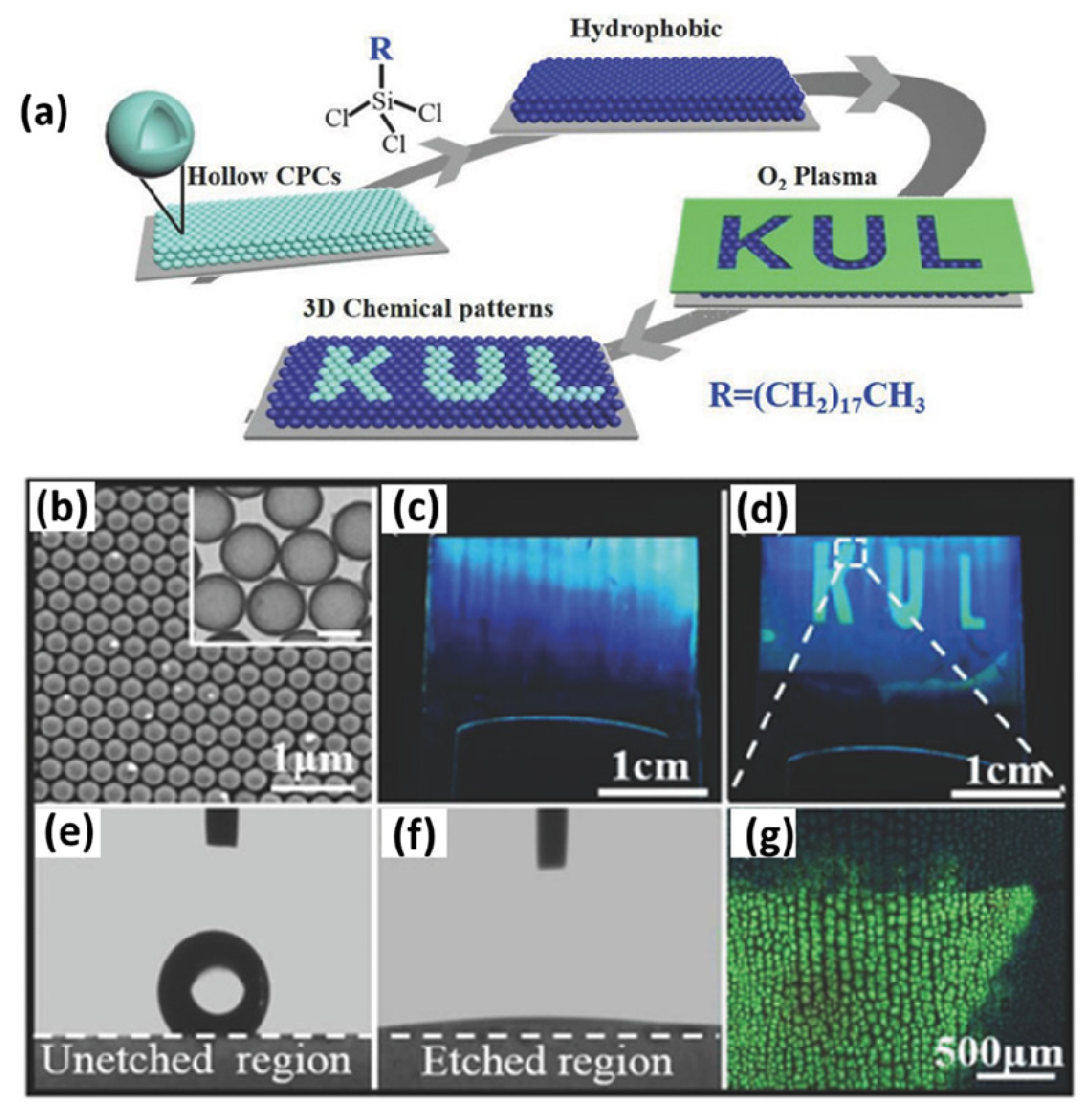
In addition to the introduction of responsive materials into the PC pattern, changing the refractive index in the pattern region by infiltrating chemicals, such as vapors or solvents, is another effective method to tune the structural color. Zhong et al. [66] reported the synthesis of invisible prints through the hydrophilic/hydrophobic modification of hollow SiO2 colloidal PC (HSCPC) film (Figure 7a). The HSPC film was composed of hollow SiO2 nanoparticles and voids, where nanoparticles were arranged into a non-packed FCC structure (Figure 7b). When the water vapor was filled into the voids between hollow particles, the reflection wavelength of the HSCPC film had a red-shift due to the increase of average reflective index caused by the exchange of water vapor, with a high reflective index (1.34), and air, with a low reflective index (1.0) in the voids. This effect can be well explained by Bragg–Snell’s law, as expressed in Equation [4] mentioned in Section 2. After the HSCPC film underwent selective hydrophilic (oxygen plasma etching) and hydrophobic (octadecyltrichlorosilane treating) modification, the hydrophilic pattern was invisible under normal conditions (Figure 7c), which is because the surface hydrophobization/hydrophilization neither changed the reflective index nor the PC structure between the pattern and the background region. The invisible “KUL” pattern can be revealed by water vapor flow, because the water vapor only diffuses into the hydrophilic pattern region, leading to an increase of the reflective index and a change of the structural color from blue to green (Figure 7d–f). In contrast, the structural color of the hydrophobic background cannot change, which makes a color contrast with the hydrophilic region. Thereby, an obvious pattern can be easily observed by the naked eye. The print can be reversibly shown and hidden by water vapor flow and evaporation. In addition, the print shows an ultrafast display speed (≈100 ms), multiple reversible cycles (at least 200 cycles) and good hiding effect (Δλ0 = 0), which favor its application in identification marking, encoding, and anti-counterfeiting.
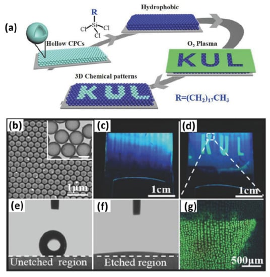
Figure 7.
Invisible colloidal PC patterns shown by vapor. (a) Schematic illustration of the preparation procedure of the invisible PC pattern. (b) The SEM image of hollow PC. (c) The optical image of the invisible PC pattern under normal circumstances. (d) The pattern revealed by water vapor flow. (g) The microscopic image of the pattern that has been revealed. (e–f) Microscopic images of the water drop deposited on the unetched region (e) and O2 plasma-etched regions (f) of the photonic print. Reused with permission from Reference [66], Copyright 2018, Wiley-VCH.
4.2. Invisible Colloidal PC Patterns Revealed by Mechanical Stretching Fabricated by Selective Immobilization
Compared with chemical stimulus, mechanical stretching or pressing is a more straightforward and readily available way for decryption of invisible patterns. To achieve an invisible pattern shown by mechanical stretching, a pattern and background region on photonic prints with the same color but different deformation capabilities should be designed.
For example, Ye and co-workers reported this type of invisible colloidal PC print, which was prepared by infiltrating a cross-linking agent (PEGDA) into pre-prepared mechanochromic PC film and selectively cross-linking the soaked mechanochromic PC film through selective UV irradiation (Figure 8a), where the mechanochromic PC film was composed of the silica colloidal crystalline array (CCA) fixed into the mixed matrix of EG and PEGMA [48]. The UV irradiation process can hardly cause the change in lattice constant, so that the irradiated region (pattern region) unprotected by a mask and un-irradiated region (background region) protected by the mask show the same color, resulting in the invisible image. The UV irradiation process can greatly improve the level of cross-linking in the pattern region, which gives it a higher hardness than the background region. When the invisible print was stretched or squeezed, the soft background region had larger deformation and color shift than the stiff pattern region, therefore revealing the pattern (Figure 8b). It is worth mentioning that the display of invisible patterns is instant once applying the external force and the pattern can be reversibly shown and hidden. Fast encryption speed and good reversibility are due to good elasticity of the background region caused by a large amount of EG solution in the mechanochromic PC system, and the elasticity of packaging material (PDMS). However, due to the inevitable evaporation of EG solution in the system, the print will lose elasticity over time and fail to display the pattern region, which means the invisible print has low durability.
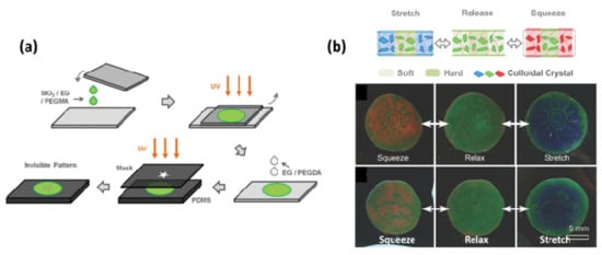
Figure 8.
(a) Schematic illustration of the preparation process of the invisible colloidal PC pattern shown by deformation. (b) Sunlight and rabbit patterns on the photonic prints hidden in a relaxed state and shown by deformation. Reused with permission from Reference [66], Copyright 2014, Wiley-VCH.
To overcome the problem of low durability caused by the presence of solvent, Ding’s group reported an all-solid-state invisible photonic print shown by deformation for anti-counterfeiting, which was prepared by selectively irradiating the polymer PC film (POF) composed of regularly arranged arrays of polystyrene core, poly(methylmethacrylate) interlayer, and poly(ethyl-acrylate) shell (PS@PMMA@PEA) nanospheres [51]. When the POF was selectively irradiated by UV light through the mask, the irradiated pattern region was hard due to the cross-linking reaction of PEA, while the un-irradiated background region was uncross-linked and showed good softness due to the good elasticity of the PEA shell. The as-prepared photonic print was invisible when the sample was not stretched (Figure 9a) because the diffraction wavelength in the pattern region (580 nm) was close to the background region (560 nm) (Figure 9b,c). The difference in diffraction wavelength was caused by the change of refractive index when cross-linking. The invisible “PhC” pattern became progressively clearer as the strain increased. When strains changed from 0% to 12%, the reflection wavelength of the soft background region changed from 560 to 490 nm (Figure 9b), showing good mechanochromic capability, and its reflection wavelength reverted to 550 nm when the strain was released. The reflection wavelength in the pattern region remained at 580 nm whether stretched or relaxed (Figure 9d). Therefore, the print had good reversibility and repeatability (Figure 9e). In addition, the print also showed good durability due to the absence of solvent in this system. When it was stored in ambient conditions for 10 months, such an invisible pattern could be reversibly shown and hidden.
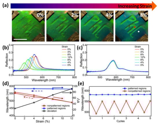
Figure 9.
The invisible photonic print shown by mechanical stretching. (a) Invisible photonic print hidden in a relaxed state and shown by tensile state. Scale bar is 1 cm. (b,c) Reflection spectra in (b) background region and (c) pattern region under a stretch–release cycle. (d) The relationship between elongation and the reflection wavelength in the background region (red line) and the pattern region (blue line). The black line shows the relationship between elongation and the reflection wavelength difference. (e) Reflection wavelength change in the pattern region (blue line) and background region (red line) in five cycles of the stretching–releasing test. Reused with permission from Reference [51], Copyright 2015, American Chemical Society.
4.3. Invisible Colloidal PC Patterns Displayed by Magnetic Field
The photonic prints as mentioned above can be hidden under normal conditions because the pattern and background region have the same structural color derived from the ordered PC structure. Differently from the invisible prints shown by chemical stimulation or mechanical stretching, photonic prints displayed by a magnetic field can achieve invisibility under normal conditions due to the same chemical color in the pattern and background region caused by the random arrangement of superparamagnetic particles in the solvents. The invisible prints shown by the magnetic field can be obtained by selectively immobilizing the background region or constructing pattern and background regions using nanoparticles with different sizes. The invisible prints have a very fast decryption speed due to fast response speed (time <1 s) of the magnetically responsive PCs [67].
4.3.1. Invisible Colloidal PC Patterns Displayed by Magnetic Field Fabricated by Selective Immobilization
The key to designing an invisible colloidal PC print displayed by a magnetic field is to create the pattern and background with the same color but different magnetochromic capabilities.
Hu’s group reported an invisible print shown by a magnetic field prepared by selectively irradiating a certain region of the photonic paper using UV light through a mask [50]. The magnetically responsive photonic paper was composed of EG droplets containing Fe3O4@C super-paramagnetic nanoparticles dispersed in the solidified PDMS matrix (Figure 10a). The UV-irradiation caused PDMS aging and resulted in the rupture of the PDMS network so that the EG solvent in the unshielded region (background region) leaked out through the ruptured PDMS, which fixed Fe3O4@C nanoparticles in the ruptured solid PDMS so that they could not respond to an applied magnetic field. Therefore, the background region remained a brown color. In contrast, in the unexposed region (pattern region) covered by the mask, the PDMS network was intact, so that the nanoparticles dispersed in EG droplets were randomly arranged without a magnetic field and arranged into an ordered 1D chain-like structure when a magnetic field was applied. The pattern respectively showed a brown color and a bright structural color when the magnetic field was withdrawn and applied (Figure 10b). The same brown color in the two regions means the print was well-hidden in the absence of a magnetic field. When applying a magnetic field, the background showed a brown chemical color and the pattern showed a bright green structural color, making the print highly visible. In addition, the state transition between the invisible and the visible state was instantaneous (responsive time usually is less than 1 s) and completely reversible, which can be attributed to the inherent advantages of magnetically responsive PCs. However, the print may exhibit low durability, because the properties of superparamagnetic nanoparticles in a ruptured solid PDMS could be easily affected by the external environment. Furthermore, the UV aging process caused the leakage of EG organic liquids, which was not environmentally friendly.
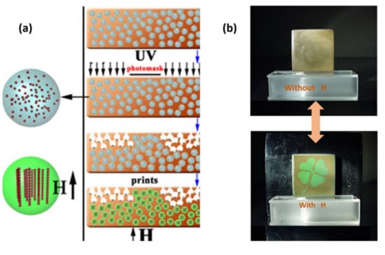
Figure 10.
Invisible print shown by a magnetic field was fabricated by selective immobilization. (a) Schematic illustration of the preparation process of the invisible colloidal PC pattern shown by magnetic field. (b) The pattern was invisible in the absence of a magnetic field but visible when applying a magnetic field. Reused with permission from Reference [50], Copyright 2012, Springer Nature.
4.3.2. Invisible Colloidal PC Patterns Displayed by Magnetic Field Fabricated by Self-Assembly of Nanoparticles with Different Sizes
Another strategy for fabricating the invisible photonic print was to use Fe3O4@SiO2 colloidal nanoparticles of different sizes to construct the pattern and background. For example, Yin’s group fabricated the print displayed by magnetic field using this strategy, where the pattern and background region were composed of EG/PDMS mixtures containing Fe3O4@SiO2 superparamagnetic particles with a core/shell size of 110/16 nm and 110/28 nm, respectively (Figure 11a,b) [68]. When the magnetic field was absent, the pattern and background both showed a brown color derived from the inherent color of the particles, thereby hiding the pattern. In contrast, the blue/green contrast could be easily observed by the naked eye when applying a strong magnetic field due to different diffraction colors of the chain-like structures self-assembled by particles with different sizes (Figure 11c). This print showed good flexibility due to the flexibility of the PDMS matrix, so it was suitable for pasting on target surfaces with various curvatures for anti-counterfeiting purposes. In addition, due to no leakage of EG in the preparation process, it was environmentally friendly. The limitation of this anti-counterfeiting print is that the pattern is not completely invisible under normal circumstances because of a deep impression on the joint between the pattern and background, which is caused by the letter molds with the same thickness as the print.
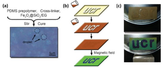
Figure 11.
Invisible colloidal PC pattern shown by the magnetic field fabricated by self-assembly of super-paramagnetic nanoparticles with different sizes. (a) The optical microscope image shows that EG solvent containing Fe3O4@SiO2 superparamagnetic particles was dispersed as circular droplets into the PDMS matrix. (b) Schematic diagram of a two-step procedure for fabricating a patterned print shown by a magnetic field. (c) The blue/green color contrast of the prints can appear with the application of an applied magnetic field. Reused with permission from Reference [67], Copyright 2008, Wiley-VCH.
4.4. Invisible Colloidal PC Pattern Shown by Electric Field Fabricated by Selective Modification of Substrates
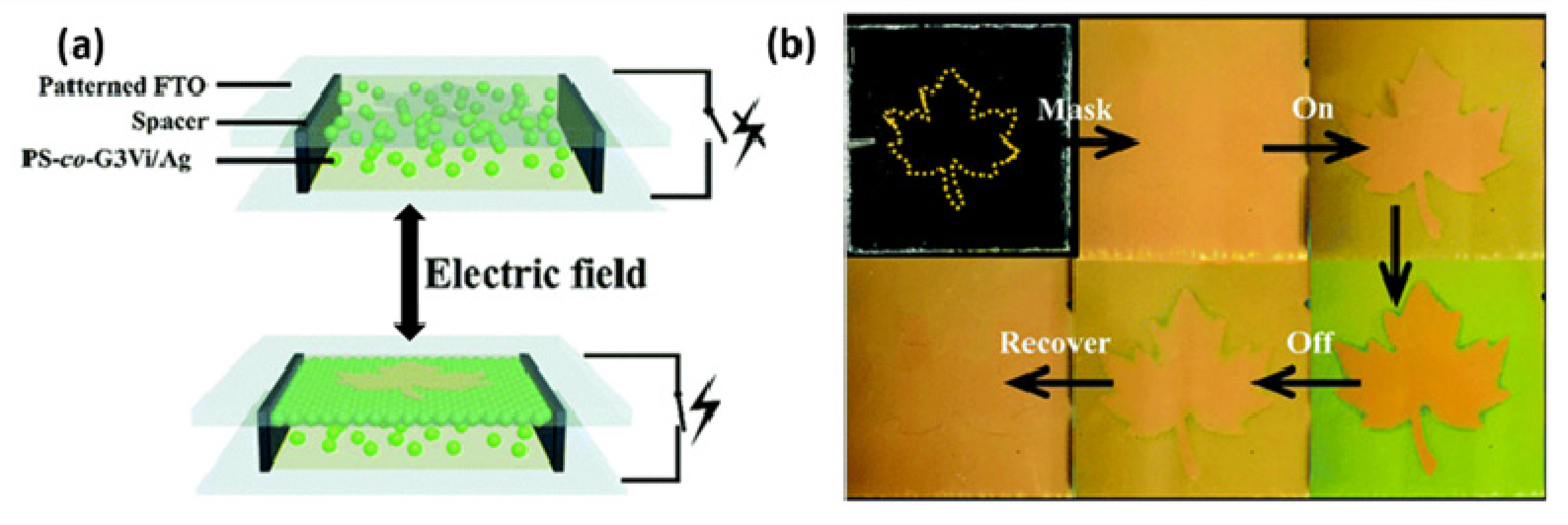
Invisible patterns can be usually obtained by selectively modifying or immobilizing a certain portion of the responsive PC. Recently, however, Chen and co-workers [14] created an invisible pattern shown by an electric field, which was realized by using a selective modified substrate obtained by taping a patterned insulating polymer onto the conductive substrate, thereby inducing the selective deposition of charged nanoparticles only on the non-patterned conductive region (background region) under an electric field. The structure of the invisible patterned photonic anti-counterfeiting device is shown in Figure 12a, where the photonic suspension containing PS-co-G3Vi/Ag composite microspheres with high surface charge density was sandwiched between two fluorine-doped tin oxide (FTO) substrates and one of the FTO glasses was glued to a “maple leaf” shaped insulated polymer film. In the absence of an electric field, the device showed a very uniform yellow color derived from the PS-co-G3Vi/Ag particle, so that the pattern was invisible (Figure 12b). Once the voltage was applied, the maple leaf-patterned region also showed a yellow color due to the disordered arrangement of particles, while the background region gradually changed from yellow to green because of the formation of an ordered PC structure composed of PS-co-G3Vi/Ag particles with a higher refractive index (n = 1.58) and deionized water with a lower refractive index (n = 1.34), resulting in the display of the maple leaf pattern. When the field was withdrawn, the pattern gradually disappeared again. Therefore, the pattern shown by the electric field possessed good hiding and display abilities, and good reversibility. However, the brittle and rigid nature of FTO substrates greatly limits their further application to flexible target surfaces.
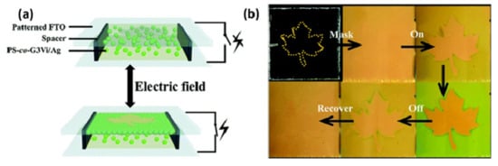
Figure 12.
Invisible colloidal PC pattern shown by an electric field. (a) Schematic diagram showing the structure of an invisible patterned photonic anti-counterfeiting device. (b) The optical images showing that the anti-counterfeiting device can be reversibly displayed and hidden with the application and removal of an electric field. Reused with permission from Reference [14], Copyright 2016, The Royal Society of Chemistry.
5. Conclusions and Perspectives
In this review, recent developments of colloidal PC based anti-counterfeiting materials composed of variable colored PC patterns, invisible PC prints, and a few other PC security materials have been summarized from the aspects of security strategies, design and fabrication principles, and identification means. These anti-counterfeiting PC materials have multiple security features, which can achieve distinct color state transitions as viewing angles change, and can realize a reversible transition between invisible state and visible state when removing or applying specific external stimuli or lighting conditions. In addition, the micro-patterned PC material can be easily obtained through a photolithography technique or inkjet-printing method. Thus, the anti-counterfeiting materials based on PCs possess almost all anti-counterfeiting features of optical anti-counterfeiting techniques in existence, such as invisible watermarks, optical variable inks, laser anti-counterfeiting markings, and miniature printing. In addition, the structural colors of PCs originate from periodic structures, not fluorescence or dye molecules, thereby providing them with higher stability than variable inks. As a result, colloidal PCs provide a new avenue to develop anti-counterfeiting systems.
However, until now, an advanced anti-counterfeiting material with fast decryption, good hiding and display effects, as well as high durability, has not been realized in reality. For example, many invisible prints fabricated by selective cross-linking methods have good display effects when applying a specific external stimulation because of the larger color contrast between the pattern and the background region. However, solvents in the PC system will evaporate over time, leading to failure in the response to the external stimuli, resulting in low durability. In addition, these prints cannot realize true (optical) invisibility because cross-linked and uncross-linked regions have different reflected wavelengths. The prints fabricated by selective hydrophilic/hydrophobic modification can be classified into two types according to their structure, with both having good hiding effects because the modification process can hardly change the structure parameters of the PC. However, one type of invisible photonic print containing a responsive polymer exhibits a slow decryption speed (several minutes). The other type, composed of well-ordered hollow nanoparticles, has an ultrafast showing time (about 200 ms) but an indistinctive display effect. To develop the performance of existing PC-based anti-counterfeiting materials, we need to study the surface modification techniques of PCs or introduce a porous structure into the PC system.
Some challenges in PC-based anti-counterfeiting materials lie beyond the PC itself. For instance, the invisible photonic print shown by an electric field has fast speed, and good hiding and revealing effects, but its rigid and brittle conductive substrates limit its further application to flexible target surfaces. Therefore, using new flexible electrodes to replace FTO, such as conductive polymer electrodes [69], will broaden their application fields.
Based on this impressive research progress, a promising future can be expected for colloidal PC-based anti-counterfeiting materials.
Author Contributions
Y.L. and L.P. designed the study; M.P. wrote the paper; L.W., S.D. and J.Z. collected the literatures; H.X., B.W. and L.Z. revised the manuscript; X.L., Y.L. and L.P. edited and proofread the manuscript.
Funding
This research was funded by National Natural Science Foundation of China (No. 51572058, 51502057, 51761135123), the National Key Research & Development Program (2016YFB0303903, 2016YFE0201600), the International Science & Technology Cooperation Program of China (2013DFR10630, 2015DFE52770), and the Foundation of Equipment Development Department (6220914010901). Heilongjiang Postdoctoral Fund (LBH-Z15078, LBH-Z16080).
Conflicts of Interest
The author declares no conflict of interest.
References
- Xia, Y.N.; Gates, B.; Li, Z.Y. Self-assembly approaches to three-dimensional photonic crystals. Adv. Mater. 2001, 13, 409–413. [Google Scholar] [CrossRef]
- Yablonovitch, E. Photonic band-gap structures. J. Opt. Soc. Am. B 1993, 10, 283–295. [Google Scholar] [CrossRef]
- Yablonovitch, E. Photonic band-gap crystals. J. Phys-Condens. Mat. 1993, 5, 2443–2460. [Google Scholar] [CrossRef]
- Ge, J.; Yin, Y. Responsive photonic crystals. Angew. Chem. Int. Ed. 2011, 50, 1492–1522. [Google Scholar] [CrossRef] [PubMed]
- John, S. Localization of light. Phys. Today 1991, 44, 32–40. [Google Scholar] [CrossRef]
- Hou, J.; Li, M.Z.; Song, Y.L. Recent advances in colloidal photonic crystal sensors: materials, structures and analysis methods. Nano Today 2018, 22, 132–144. [Google Scholar] [CrossRef]
- Rinne, S.A.; García-Santamaría, F.; Braun, P.V. Embedded cavities and waveguides in three-dimensional silicon photonic crystals. Nat. Photonics 2007, 2, 52–56. [Google Scholar] [CrossRef]
- Kim, S.-H.; Kim, S.-H.; Jeong, W.C.; Yang, S.-M. Low-threshold lasing in 3D dye-doped photonic crystals derived from colloidal self-assemblies. Chem. Mater. 2009, 21, 4993–4999. [Google Scholar] [CrossRef]
- Knight, J.C. Photonic crystal fibres. Nature 2003, 424, 847. [Google Scholar] [CrossRef]
- Zhang, H.; Zhang, X.; Li, H.; Deng, Y.; Xi, L.; Tang, X.; Zhang, W. The orbital angular momentum modes supporting fibers based on the photonic crystal fiber structure. Crystals 2017, 7, 286. [Google Scholar] [CrossRef]
- Du, C.; Wang, Q.; Zhao, Y.; Hu, S. Ultrasensitive long-period gratings sensor works near dispersion turning point and mode transition region by optimally designing a photonic crystal fiber. Opt. Laser Technol. 2019, 112, 261–268. [Google Scholar] [CrossRef]
- Wang, S.; Chen, H.; Chen, M.; Xie, S. Ultrawideband pulse generation and bipolar coding based on optical cross-polarization modulation in highly nonlinear photonic crystal fiber. Opt. Eng. 2009, 48, 105006. [Google Scholar] [CrossRef]
- Lee, S.Y.; Kim, S.-H.; Hwang, H.; Sim, J.Y.; Yang, S.-M. Controlled pixelation of inverse opaline structures towards reflection-mode displays. Adv. Mater. 2014, 26, 2391–2397. [Google Scholar] [CrossRef] [PubMed]
- Chen, M.; Tian, Y.; Zhang, J.; Hong, R.; Chen, L.; Chen, S.; Son, D.Y. Fabrication of crack-free photonic crystal films via coordination of microsphere terminated dendrimers and their performance in invisible patterned photonic displays. J. Mater. Chem. C 2016, 4, 8765–8771. [Google Scholar] [CrossRef]
- Yang, D.P.; Ye, S.Y.; Ge, J.P. From metastable colloidal crystalline arrays to fast responsive mechanochromic photonic gels: an organic gel for deformation-based display panels. Adv. Funct. Mater. 2014, 24, 3197–3205. [Google Scholar] [CrossRef]
- Kuang, M.; Wang, J.; Bao, B.; Li, F.; Wang, L.; Jiang, L.; Song, Y. Inkjet printing patterned photonic crystal domes for wide viewing-angle displays by controlling the sliding three phase contact line. Adv. Opt. Mater. 2014, 2, 34–38. [Google Scholar] [CrossRef]
- Zhou, J.; Zhou, T.J.; Li, J.G.; He, K.B.; Qiu, Z.R.; Qiu, B.C.; Zhang, Z.Y. Proposal and numerical study of a flexible visible photonic crystal defect cavity for nanoscale strain sensors. Opt. Express 2017, 25, 23645–23653. [Google Scholar] [CrossRef] [PubMed]
- Cai, Z.; Smith, N.L.; Zhang, J.T.; Asher, S.A. Two-dimensional photonic crystal chemical and biomolecular sensors. Anal. Chem. 2015, 87, 5013–5025. [Google Scholar] [CrossRef]
- Yang, D.Q.; Wang, B.; Chen, X.; Wang, C.; Ji, Y.F. Ultracompact on-chip multiplexed sensor array based on dense integration of flexible 1D photonic crystal nanobeam cavity with large free spectral range and high Q-factor. IEEE Photonics J. 2017, 9, 1–12. [Google Scholar]
- Lee, H.S.; Shim, T.S.; Hwang, H.; Yang, S.-M.; Kim, S.-H. Colloidal photonic crystals toward structural color palettes for security materials. Chem. Mater. 2013, 25, 2684–2690. [Google Scholar] [CrossRef]
- Heo, Y.; Kang, H.; Lee, J.S.; Oh, Y.K.; Kim, S.H. Lithographically encrypted inverse opals for anti-counterfeiting applications. Small 2016, 12, 3819–3826. [Google Scholar] [CrossRef] [PubMed]
- Meng, Y.; Liu, F.F.; Umair, M.M.; Ju, B.Z.; Zhang, S.F.; Tang, B.T. Patterned and iridescent plastics with 3D inverse opal structure for anticounterfeiting of the banknotes. Adv. Opt. Mater. 2018, 6, 1701351. [Google Scholar] [CrossRef]
- Hu, H.; Chen, Q.-W.; Tang, J.; Hu, X.-Y.; Zhou, X.-H. Photonic anti-counterfeiting using structural colors derived from magnetic-responsive photonic crystals with double photonic bandgap heterostructures. J. Mater. Chem. 2012, 22, 11048–11053. [Google Scholar] [CrossRef]
- Zhang, J.; Yang, S.; Tian, Y.; Wang, C.F.; Chen, S. Dual photonic-bandgap optical films towards the generation of photonic crystal-derived 2-dimensional chemical codes. Chem. Commun. 2015, 51, 10528–10531. [Google Scholar] [CrossRef] [PubMed]
- Yang, D.; Qin, Y.; Ye, S.; Ge, J. Polymerization-induced colloidal assembly and photonic crystal multilayer for coding and decoding. Adv. Funct. Mater. 2014, 24, 817–825. [Google Scholar] [CrossRef]
- Yablonovitch, E.; Gmitter, T.J.; Leung, K.M. Photonic band structure: The face-centered-cubic case employing nonspherical atoms. Phys. Rev. Lett. 1991, 67, 2295–2298. [Google Scholar] [CrossRef] [PubMed]
- Roundy, D.; Joannopoulos, J. Photonic crystal structure with square symmetry within each layer and a three-dimensional band gap. Appl. Phys. Lett. 2003, 82, 3835–3837. [Google Scholar] [CrossRef]
- Král, Z.; Ferré-Borrull, J.; Trifonov, T.; Marsal, L.F.; Rodriguez, A.; Pallarès, J.; Alcubilla, R. Mid-IR characterization of photonic bands in 2D photonic crystals on silicon. Thin Solid Films 2008, 516, 8059–8063. [Google Scholar] [CrossRef]
- Schaffner, M.; England, G.; Kolle, M.; Aizenberg, J.; Vogel, N. Combining bottom-up self-assembly with top-down microfabrication to create hierarchical inverse opals with high structural order. Small 2015, 11, 4334–4340. [Google Scholar] [CrossRef]
- Meseguer, F.; Blanco, A.; Miguez, H.; Garcia-Santamaria, F.; Ibisate, M.; Lopez, C. Synthesis of inverse opals. Colloid. Surface. A 2002, 202, 281–290. [Google Scholar] [CrossRef]
- Cui, L.; Zhang, Y.; Wang, J.; Ren, Y.; Song, Y.; Jiang, L. Ultra-fast fabrication of colloidal photonic crystals by spray coating. Macromol. Rapid Commun. 2009, 30, 598–603. [Google Scholar] [CrossRef]
- Yang, H.W.; Pan, L.; Han, Y.P.; Ma, L.H.; Li, Y.; Xu, H.B.; Zhao, J.P. A visual water vapor photonic crystal sensor with PVA/SiO2 opal structure. Appl. Surf. Sci. 2017, 423, 421–425. [Google Scholar] [CrossRef]
- Jiang, P.; McFarland, M.J. Large-scale fabrication of wafer-size colloidal crystals, macroporous polymers and nanocomposites by spin-coating. J. Am. Chem. Soc. 2004, 126, 13778–13786. [Google Scholar] [CrossRef]
- Liu, X.; Zhao, J.P.; Hao, J.; Su, B.L.; Li, Y. 3D ordered macroporous germanium fabricated by electrodeposition from an ionic liquid and its lithium storage properties. J. Mater. Chem. A 2013, 1, 15076–15081. [Google Scholar] [CrossRef]
- Johnson, N.P.; McComb, D.W.; Richel, A.; Treble, B.M.; De la Rue, R.M. Synthesis and optical properties of opal and inverse opal photonic crystals. Synthetic Met. 2001, 116, 469–473. [Google Scholar] [CrossRef]
- Ye, Y.H.; LeBlanc, F.; Hache, A.; Truong, V.V. Self-assembling three-dimensional colloidal photonic crystal structure with high crystalline quality. Appl. Phys. Lett. 2001, 78, 52–54. [Google Scholar] [CrossRef]
- Wu, S.; Liu, B.; Su, X.; Zhang, S. Structural color patterns on paper fabricated by inkjet printer and their application in anticounterfeiting. J. Phys. Chem. Lett. 2017, 8, 2835–2841. [Google Scholar] [CrossRef]
- Hou, J.; Li, M.; Song, Y. Patterned colloidal photonic crystals. Angew. Chem. Int. Ed. 2018, 57, 2544–2553. [Google Scholar] [CrossRef]
- Bai, L.; Xie, Z.; Wang, W.; Yuan, C.; Zhao, Y.; Mu, Z.; Zhong, Q.; Gu, Z. Bio-inspired vapor-responsive colloidal photonic crystal patterns by inkjet printing. Acs Nano 2014, 8, 11094–11100. [Google Scholar] [CrossRef]
- Xiong, C.; Zhao, J.; Wang, L.; Geng, H.; Xu, H.; Li, Y. Trace detection of homologues and isomers based on hollow mesoporous silica sphere photonic crystals. Mater. Horiz. 2017, 4, 862–868. [Google Scholar] [CrossRef]
- Ma, H.R.; Zhu, M.X.; Luo, W.; Li, W.; Fang, K.; Mou, F.Z.; Guan, J.G. Free-standing, flexible thermochromic films based on one-dimensional magnetic photonic crystals. J. Mater. Chem. C 2015, 3, 2848–2855. [Google Scholar] [CrossRef]
- Chen, K.; Fu, Q.; Ye, S.; Ge, J. Multicolor printing Using electric-field-responsive and photocurable photonic crystals. Adv. Funct. Mater. 2017, 27, 1702825. [Google Scholar] [CrossRef]
- Ge, J.; Hu, Y.; Yin, Y. Highly tunable superparamagnetic colloidal photonic crystals. Angew. Chem. Int. Ed. 2007, 46, 7428–7431. [Google Scholar] [CrossRef] [PubMed]
- Johnson, S.G.; Mekis, A.; Fan, S.H.; Joannopoulos, J.D. Molding the flow of light. Comput. Sci. Eng. 2001, 3, 38–47. [Google Scholar] [CrossRef]
- Ye, X.Z.; Qi, L.M. Recent advances in fabrication of monolayer colloidal crystals and their inverse replicas. Sci.China Chem. 2014, 57, 58–69. [Google Scholar] [CrossRef]
- Fenzl, C.; Hirsch, T.; Wolfbeis, O.S. Photonic crystals for chemical sensing and biosensing. Angew. Chem. Int. Ed. 2014, 53, 3318–3335. [Google Scholar] [CrossRef] [PubMed]
- Fudouzi, H. Fabricating high-quality opal films with uniform structure over a large area. J. Colloid Interf. Sci. 2004, 275, 277–283. [Google Scholar] [CrossRef]
- Ye, S.; Fu, Q.; Ge, J. Invisible photonic prints shown by deformation. Adv. Funct. Mater. 2014, 24, 6430–6438. [Google Scholar] [CrossRef]
- Ye, S.; Ge, J. Soaking based invisible photonic print with a fast response and high resolution. J. Mater. Chem. C 2015, 3, 8097–8103. [Google Scholar] [CrossRef]
- Hu, H.; Tang, J.; Zhong, H.; Xi, Z.; Chen, C.; Chen, Q. Invisible photonic printing: Computer designing graphics, UV printing and shown by a magnetic field. Sci. Rep. 2013, 3, 1484. [Google Scholar] [CrossRef]
- Ding, T.; Cao, G.; Schaefer, C.G.; Zhao, Q.; Gallei, M.; Smoukov, S.K.; Baumberg, J.J. Revealing invisible photonic inscriptions: images from strain. Acs Appl. Mater. Inter. 2015, 7, 13497–13502. [Google Scholar] [CrossRef]
- Xuan, R.; Ge, J. Invisible photonic prints shown by water. J. Mater. Chem. C 2012, 22, 367–372. [Google Scholar] [CrossRef]
- Hou, J.; Zhang, H.; Su, B.; Li, M.; Yang, Q.; Jiang, L.; Song, Y. Four-dimensional screening anti-counterfeiting pattern by inkjet printed photonic crystals. Chem. Asian J. 2016, 11, 2680–2685. [Google Scholar] [CrossRef]
- Nam, H.; Song, K.; Ha, D.; Kim, T. Inkjet printing based mono-layered photonic crystal patterning for anti-counterfeiting structural colors. Sci. Rep. 2016, 6, 30885. [Google Scholar] [CrossRef]
- Shang, S.; Zhang, Q.; Wang, H.; Li, Y. Fabrication of magnetic field induced structural colored films with tunable colors and its application on security materials. J. Colloid Interf. Sci. 2017, 485, 18–24. [Google Scholar] [CrossRef]
- Meng, Z.; Wu, S.; Tang, B.; Ma, W.; Zhang, S. Structurally colored polymer films with narrow stop band, high angle-dependence and good mechanical robustness for trademark anti-counterfeiting. Nanoscale 2018, 10, 14755–14762. [Google Scholar] [CrossRef]
- Wang, M.; Yin, Y. Magnetically responsive nanostructures with tunable optical properties. J. Am. Chem. Soc. 2016, 138, 6315–6323. [Google Scholar] [CrossRef]
- Hu, H.; Chen, C.; Chen, Q. Magnetically controllable colloidal photonic crystals: Unique features and intriguing applications. J. Mater. Chem. C 2013, 1, 6013–6030. [Google Scholar] [CrossRef]
- Hu, H.B.; Zhong, H.; Chen, C.L.; Chen, Q.W. Magnetically responsive photonic watermarks on banknotes. J. Mater. Chem. C 2014, 2, 3695–3702. [Google Scholar] [CrossRef]
- Ge, J.P.; Yin, Y.D. Magnetically responsive colloidal photonic crystals. J. Mater. Chem. 2008, 18, 5041–5045. [Google Scholar] [CrossRef]
- Li, H.; Li, C.; Sun, W.; Wang, Y.; Hua, W.; Liu, J.; Zhang, S.; Chen, Z.; Wang, S.; Wu, Z.; et al. Single-stimulus-induced modulation of multiple optical properties. Adv. Mater. 2019, 31, 1900388. [Google Scholar] [CrossRef]
- Weissman, J.M.; Sunkara, H.B.; Tse, A.S.; Asher, S.A. Thermally switchable periodicities and diffraction from mesoscopically ordered materials. Science 1996, 274, 959. [Google Scholar] [CrossRef]
- Takeoka, Y.; Watanabe, M. Tuning structural color changes of porous thermosensitive gels through quantitative adjustment of the cross-linker in pre-gel solutions. Langmuir 2003, 19, 9104–9106. [Google Scholar] [CrossRef]
- Kumoda, M.; Watanabe, M.; Takeoka, Y. Preparations and optical properties of ordered arrays of submicron gel particles: Interconnected state and trapped state. Langmuir 2006, 22, 4403–4407. [Google Scholar] [CrossRef]
- Zhao, Z.; Wang, H.; Shang, L.; Yu, Y.; Fu, F.; Zhao, Y.; Gu, Z. Bioinspired heterogeneous structural color stripes from capillaries. Adv. Mater. 2017, 29, 1704569. [Google Scholar] [CrossRef]
- Zhong, K.; Li, J.; Liu, L.; Van Cleuvenbergen, S.; Song, K.; Clays, K. Instantaneous, simple, and reversible revealing of invisible patterns encrypted in robust hollow sphere colloidal photonic crystals. Adv. Mater. 2018, 30. [Google Scholar] [CrossRef]
- Jia, X.; Wang, K.; Wang, J.; Hu, Y.; Shen, L.; Zhu, J. Full-color photonic hydrogels for pH and ionic strength sensing. Eur Polym J. 2016, 83, 60–66. [Google Scholar] [CrossRef]
- Ge, J.; Yin, Y. Magnetically tunable colloidal photonic structures in alkanol solutions. Adv. Mater. 2008, 20, 3485–3491. [Google Scholar] [CrossRef]
- Zhou, L.; Yu, M.; Chen, X.; Nie, S.; Lai, W.-Y.; Su, W.; Cui, Z.; Huang, W. Screen-printed poly(3,4-ethylenedioxythiophene):poly(styrenesulfonate) grids as ITO-free anodes for flexible organic light-emitting diodes. Adv. Funct. Mater. 2018, 28, 1705955. [Google Scholar] [CrossRef]


© 2019 by the authors. Licensee MDPI, Basel, Switzerland. This article is an open access article distributed under the terms and conditions of the Creative Commons Attribution (CC BY) license (http://creativecommons.org/licenses/by/4.0/).