Abstract
Tin bronze/steel bimetallic is a widely utilized industrial material in the field of sliding bearing applications. Arc cladding technology represents an emerging method for fabricating tin bronze/steel bimetallic materials; however, research on their microstructure and mechanical properties remains limited. This study investigates the microstructural characteristics and mechanical behavior of tin bronze/steel bimetallic materials produced via the arc cladding process, with particular emphasis on the effects of annealing treatment on these properties. The tin bronze layer consists of a fine-grained zone, a columnar dendritic zone, and a freely dendritic zone. The tin bronze/steel bimetallic material exhibits high mechanical strength and strong interfacial bonding. Nevertheless, during three-point bending tests, cracks are observed in the tin bronze layer. When annealed at temperatures ranging from 300 °C to 700 °C, the tensile strength, shear strength, and hardness of the material decrease, while the elongation increases significantly. Moreover, no cracking occurs during three-point bending tests. Upon reaching an annealing temperature of 800 °C, the overall mechanical performance deteriorates rapidly. An annealing temperature of 300 °C is identified as an optimal parameter for achieving favorable mechanical properties.
1. Introduction
Tin bronze exhibits excellent corrosion resistance, fatigue resistance, wear resistance, and high mechanical strength [1]. Additionally, it is lead-free and environmentally benign. Therefore, tin bronze has been extensively applied in high-wear-resistant structural components such as sliding bearings, bearing shells, guide rails, and rocker arms [2,3]. As a bearing material, tin bronze is typically combined with steel plates to form tin bronze/steel bimetallic materials. Commonly employed techniques for fabricating tin bronze/steel bimetallic materials include powder sintering and continuous casting/rolling processes. In the powder sintering method, tin bronze alloy powder is spread onto steel plates, followed by compaction and sintering to produce bimetallic materials [4,5]. However, a drawback of this technique is the relatively low bonding strength between the two materials. The tin bronze layer often exhibits low density, coarse grain structure, and porosity, which can reduce the load-bearing capacity and fatigue strength of the bimetallic materials. High-strength and defect-free tin bronze/steel bimetallic plates can be produced via the casting/rolling process [6]; however, macrosegregation tends to occur within the tin bronze layer. Furthermore, the contact between molten tin bronze and solid steel substrates may induce liquid metal embrittlement [7,8,9,10,11], leading to through-cracks and embrittlement failure in the steel.
In recent years, researchers have employed advanced fabrication techniques such as arc spraying, laser cladding, plasma spraying, high-velocity oxygen fuel (HVOF) spraying, and cold spraying to deposit tin bronze alloy layers onto steel substrates. While all these methods offer distinct advantages, they also present certain limitations [12,13]. For example, coatings fabricated with arc spraying, plasma spraying, and HVOF spraying are often associated with defects such as oxidation, porosity, and the presence of unmelted particles. Although laser cladding enables metallurgical bonding between tin bronze and steel, it is accompanied by relatively high costs and challenges such as a thick fusion zone, porosity, and hot cracking. Cold spraying effectively mitigates the oxidation and thermal deformation commonly observed in conventional thermal deposition processes; however, it fails to establish a fully metallurgical bond between the coating and the substrate, and the resulting coating typically exhibits a certain degree of porosity.
Arc cladding is a process that utilizes an arc as a heat source to melt metal wire and rapidly scans the surface of dissimilar metal substrates with extremely low line energy. This causes molten droplets to transfer quickly to the substrate, forming micro-melt pools that subsequently solidify at a high rate, resulting in coatings with unique properties [14,15]. The fundamental principle of arc cladding is similar to the traditional arc surfacing welding. Through the action of the arc, metallurgical bonding between the cladding layer and the substrate can be achieved. Macroscopically, the thickness of the cladding layer in arc cladding is generally lower than that in arc surfacing welding, typically ranging from 0.5 to 1.0 mm, considerably thicker than micron-level coatings obtained through arc spraying. Microscopically, compared with arc surfacing welding, arc cladding exhibits a shallower penetration depth, and nearly zero dilution rate. Wei [16] fabricated a Babbitt alloy coating on a steel substrate using arc cladding. A metallurgical bond was achieved between the Babbitt alloy and the steel substrate, and the interface of the two materials was nearly a straight line. Chen [17] also employed arc cladding to produce an AlSi12 coating on a steel substrate. The interface between the coating and the steel substrate was found to be similar to that observed in the Babbitt alloy and steel system, with minimal penetration depth. A strong metallurgical bond was formed at the bimetallic interface.
The dissimilar welding of copper alloys to steel has been extensively investigated. Studies indicate that despite the substantial differences in physical properties between copper and steel, a reliable joint can still be achieved through optimization of process parameters and the use of advanced welding equipment [18,19,20,21]. However, certain challenges remain in the arc cladding of tin bronze onto steel substrates. Compared with Babbitt alloys and aluminum-based alloys, tin bronze possesses a higher melting point and thus requires greater arc heat input. Consequently, achieving a cladding layer with thinner thickness, wide coverage, and low dilution on thin steel substrates remains technically challenging. Furthermore, tin bronze exhibits greater penetration into steel substrates than other copper alloys, which can lead to the embrittlement of the steel. Meanwhile, no systematic research has been conducted on the microstructure, mechanical properties, and bonding performance of tin bronze/steel bimetallic materials fabricated with arc cladding.
In this study, tin bronze layers were fabricated on the steel substrate to form the tin bronze/steel bimetallic materials using the arc cladding technology. A metallurgical bond was successfully established between the tin bronze and the steel substrate. The microstructure, mechanical properties, and bonding performance of the tin bronze/steel bimetallic material were systematically investigated. Additionally, the influence of heat treatment process parameters on the microstructural evolution and performance characteristics of the tin bronze/steel bimetallic was also examined.
2. Materials and Methods
Commercial tin bronze wires with a diameter of 1.2 mm were employed for the arc cladding of the tin bronze layer. Generally, tin bronze is prone to producing infiltrated cracks in steel substrates due to the serious liquid metal embrittlement phenomenon. Nickel, however, has been shown to effectively inhibit such crack formation [21]. When a nickel layer is prepared on the steel, nickel melts during the arc cladding process and leads to nickel enrichment at the interface between tin bronze and steel, which reduces the infiltration of tin bronze into steel grain boundaries. Nickel does not harm the grain boundaries of steel, and a small amount of nickel does not affect the properties of tin bronze. Therefore, nickel-plated steel was selected as the substrate material. The dimensions of the steel were 60 × 200 × 2 mm3, and the thickness of the nickel plating layer was 10 μm. The detailed chemical composition of the experimental materials is presented in Table 1. Arc cladding experiments were performed using a welding robot (Yaskawa MA1440, YASKAWA Electric Corporation, Kitakyushu, Japan) integrated with a cold metal transfer (CMT) welding power source (Yaskawa RD350, YASKAWA Electric Corporation, Kitakyushu, Japan). The specific arc cladding process parameters are summarized in Table 2. The arc cladding was conducted in a weaving pattern, as illustrated in Figure 1a. The heat treatment experiment of the tin bronze/steel bimetallic material was conducted in a box-type resistance furnace (SIOM SG-XL1200, Shanghai Institute of Optics and Fine Mechanics, Chinese Academy of Sciences, Shanghai, China). Annealing temperatures were set within the range of 300 to 800 °C, with a holding time of two hours. Following heat treatment, the samples were subjected to furnace cooling. Three samples were used for each temperature used in the heat treatment. The properties and microstructures of the three samples were similar. Therefore, we selected data and image from the most representative sample. The microstructure of the tin bronze/steel bimetallic material was examined using optical microscopy (OM, Motic BA310Met-T, Motic Industrial Group Co., Ltd., Xiamen, China), scanning electron microscopy (SEM, Zeiss SIGMA 300, Carl Zeiss AG, Oberkochen, Germany, Accelerating voltage: 20 KV, Spot size: 4.0–5.0 nm, Detector: Secondary electrons, Working distance: 4.3–21.6 mm), and transmission electron microscopy (TEM, Talos F200X, Thermo Fisher Scientific, Waltham, America, Electron source: High-brightness Schottky X-FEG electron source, Acceleration voltage: 200 KV, Mode point resolution: 0.25 nm, Mode information limit: 0.12 nm).

Table 1.
Chemical composition (wt%) of the experimental materials. Adapted from Ref. [22].

Table 2.
Detailed parameters.
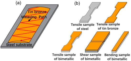
Figure 1.
Experimental methods: (a) schematic diagram of arc cladding experiment; (b) tensile, shear, and bending samples.
The mechanical properties of the tin bronze/steel bimetallic material before and after heat treatment were systematically evaluated. The evaluation included the tensile properties of the steel substrate, the tin bronze layer, and the bimetallic material as a whole, as well as the interfacial shear properties between the two materials and the bending behavior of the bimetallic materials. The sample preparation process is illustrated in Figure 1b, where the tin bronze layer has a thickness of 0.5 mm and the steel substrate measures 2 mm in thickness. Tensile testing was carried out using an electronic universal testing machine (3S CMT5105, Shenzhen SANS Testing Instruments Co., Ltd., Shenzhen, China) at a speed of 2 mm/min. Interfacial shear testing was also performed on the same apparatus at a shear rate of 1 mm/min. Furthermore, a 180° three-point bending test was conducted at a speed of 1 mm/min, with the tin bronze layer positioned externally and the steel substrate internally, to assess post-deformation cracking behavior. Following sample fracture, the morphology of the fracture was examined and analyzed under SEM. An automatic microhardness tester (FUTURE-TECH: FM-700, Future Tech Co., Ltd., Kawasaki, Japan) was adopted to perform hardness testing on the cladding layer and steel substrate. The applied load during measurement was 300 g, and the holding time was 15 s.
3. Results and Discussion
3.1. Microstructure and Properties Before Annealing
The macroscopic morphology of tin bronze/steel bimetallic is shown in Figure 2a. Two cladding layers are fabricated on the steel. There are no macroscopic defects on the cladding layers such as cracks, pores, and discontinuity. The cross-sectional morphology of the tin bronze/steel bimetallic is shown in Figure 2b. The thickness of the cladding layer is about 1 mm and the thickness is relatively uniform. The interface between tin bronze and steel exhibits a linear morphology, indicating that the degree of steel melting remains relatively limited during the arc cladding process. This observation demonstrates a marked distinction from conventional welding processes, which are characterized by curved fusion lines and expanded fusion zones [23].
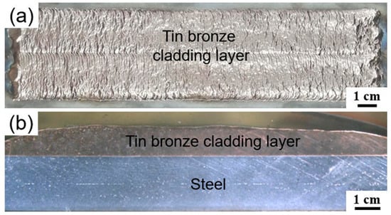
Figure 2.
Morphology of tin bronze/steel bimetallic: (a) macroscopic morphology; (b) cross-sectional morphology.
The chemical composition of the cladding layer is largely consistent with that of the tin bronze wire. The relatively low content of Fe and Ni elements in the cladding layer indicates that the steel substrate was basically not melted during the arc cladding process (Figure 3a). The tin bronze cladding layer is composed of fine grains, columnar dendrites, and equiaxed dendrites. The fine-grained area is located near the tin bronze/steel interface. Columnar dendrites are located above the fine-grained area, and the equiaxed dendrites are located above the columnar dendrites. The distribution of the microstructure is shown in Figure 3c. During the arc cladding process, the steel substrate exhibits a relatively low initial temperature, whereas the tin bronze droplets possess a significantly higher temperature. Upon contact with the steel, the molten droplets undergo rapid cooling and nucleation, leading to the formation of finer grains. Due to the thin thickness of the steel substrate, the temperature of the steel rises rapidly, and the cooling effect weakens, resulting in a thinner thickness of the fine-grained zone at the interface. The grains grow in the opposite direction of heat dissipation, thus forming a columnar dendritic zone. In the internal region of the cladding layer far from the tin bronze/steel interface, the temperature gradient further decreases, and significant compositional undercooling occurs [24,25], thus facilitating nucleation within this region. Grains exhibit dendritic growth in multiple directions, ultimately resulting in the formation of a free dendritic microstructure. Transmission electron microscopy (TEM) observations revealed that a strong metallurgical bond is formed between tin bronze and steel, with a well-defined interface present between the two materials (Figure 3d).
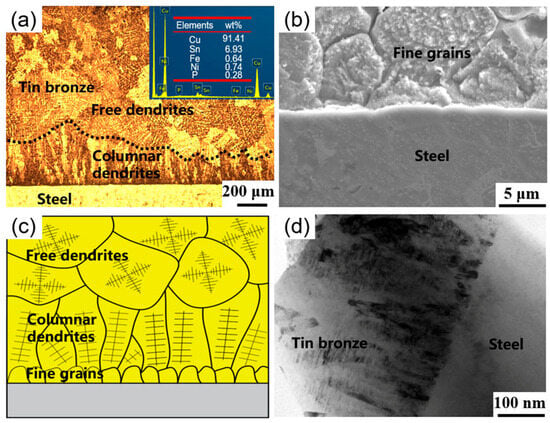
Figure 3.
Microstructure of tin bronze/steel bimetallic: (a) microstructure and chemical composition; (b) fine grains near the interface; (c) distribution of the microstructures; and (d) metallurgical bond between tin bronze and steel.
Figure 4a,b present the scanning electron microscope (SEM) morphology and the distribution of the tin element for the free dendrites, respectively. Free dendrites exhibit evident compositional segregation [26]. The tin content within the dendrites is relatively low, whereas a higher concentration is observed at the dendrite boundaries. Figure 4c displays the magnified morphology of the tin-rich region. It is evident that this region comprises three distinct phases, labeled as A1, A2, and A3. The region was examined using transmission electron microscopy (TEM). The results indicate that region A1 corresponds to the δ-Cu41Sn11 phase, region A2 to the α-Cu(Sn) phase, and region A3 to the Cu3P phase. Therefore, the regions exhibiting relatively higher tin content between dendrites constitute ternary structures composed of δ-Cu41Sn11, α-Cu(Sn), and Cu3P.
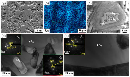
Figure 4.
Analysis of free dendrite: (a) microstructure of free dendrite; (b) distribution of the tin element; (c) δ-Cu41Sn11 + α-Cu (Sn) + Cu3P ternary structure; and (d,e) results of TEM.
Tensile property tests were conducted on the tin bronze layer, the steel substrate, and the tin bronze/steel bimetallic material. The tensile specimens are shown in Figure 1b. The thickness of the tin bronze tensile sample is 0.5 mm, that of the steel-based tensile sample is 2 mm, and that of the bimetallic tensile sample is 2.5 mm. Figure 5 presents the stress-displacement curve and Table 3 presents the tensile strength and elongation after fracture. The tin bronze cladding layer exhibits a tensile strength of 487.0 MPa and an elongation after fracture of 14.3%. The results demonstrate that the tin bronze layer has excellent mechanical properties [27].
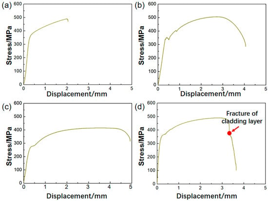
Figure 5.
Stress-displacement curves during tensile processes for different materials: (a) tin bronze layer; (b) steel after arc cladding; (c) original steel before arc cladding; and (d) tin bronze/steel bimetallic.

Table 3.
Tensile strength and elongation.
Following arc cladding, the strength of the steel substrate increased from 414.9 MPa in the original state to 505.1 MPa, whereas the elongation after fracture decreased from 36.8% to 29.1%. The tensile strength of the tin bronze/steel bimetallic material is 490.1 MPa, with an elongation after fracture of 26.6%. The tensile strength and elongation of the bimetallic material are situated within the range defined by the tin bronze and the steel [28]. During the tensile testing of the bimetallic material, the tin bronze cladding layer fractures initially, with the fracture location indicated by the red dot in Figure 5d.
Figure 6 presents the hardness distribution of the tin bronze/steel bimetallic material in comparison with that of the initial steel substrate prior to arc cladding. The hardness of the tin bronze layer ranges from 111 to 116 HV. The steel substrate exhibits a hardness of 132 to 135 HV prior to arc cladding, which increases from 136 to 146 HV following the arc cladding process. The steel substrate adjacent to the tin bronze layer underwent arc heating and air cooling processes, resulting in the transformation of granular pearlite into lamellar pearlite, which consequently enhanced the strength and hardness of the steel base plate. The steel substrate at locations distant from the tin bronze layer experiences reduced influence from arc heating, leading to diminished formation of lamellar pearlite and consequently a minimal increase in hardness.
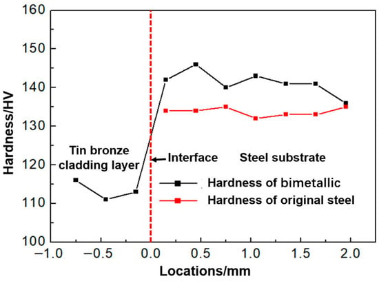
Figure 6.
Hardness distribution of bimetallic material and original steel.
Regardless of whether the material is tin bronze or steel substrate, the fracture morphology exhibits numerous dimples (Figure 7a–c), indicating that both the steel and the tin bronze layer have undergone ductile fracture. Following the fracture of the tin bronze/steel bimetallic material, the tin bronze and steel remained well bonded (Figure 7d). Although the strength and elongation of the steel substrate and tin bronze are different, these two metallic materials exhibit coordinated deformation during the tensile process, with no peeling or cracking observed at the interface.
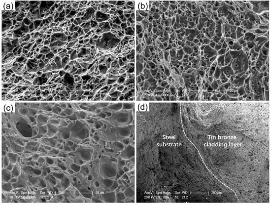
Figure 7.
Fracture morphology: (a) steel before arc cladding; (b) steel after arc cladding; (c) tin bronze layer; and (d) tin bronze/steel bimetallic.
The performance of the interfacial bonding between the tin bronze and the steel substrate was evaluated through shear testing. The stress-displacement curve obtained during the shearing process is presented in Figure 8a, with the corresponding shear strength of the specimen measured at 193 MPa. The macroscopic morphology of the shear fracture surface, along with the fracture location and microscopic morphology, is presented in Figure 8b,c. The fracture exhibits a dimpled morphology, which indicates the occurrence of ductile fracture during the shearing process. In contrast to the equiaxed dimples observed at the tensile fracture zone, the dimples present here are characterized as inclined shear dimples [29]. The compositional analysis of the fracture (Figure 8d) indicate that the primary constituents on the fracture zone are copper, suggesting that the shear fracture occurred within the tin bronze layer (Figure 8c). This further confirms the strong interfacial bonding between the tin bronze layer and the steel substrate.
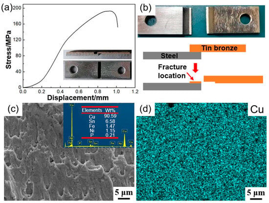
Figure 8.
Shear strength of tin bronze/steel bimetallic: (a) stress-displacement curve; (b) appearance of sample after shear fracture; (c) morphology of shear fracture; and (d) element distribution of fracture zone.
Figure 9 presents the morphological characteristics of the tin bronze/steel bimetallic following three-point bending at 180°, together with the corresponding load/displacement curve during the bending process. The tin bronze layer is positioned on the outer side with a thickness of 0.5 mm, while the steel substrate is located on the inner side with a thickness of 2 mm. When the compression displacement reaches the length of the bending diameter (20 mm), corresponding to a bending angle of 180°, the load attains its maximum value and subsequently decreases rapidly. No delamination was observed between the cladding layer and the steel substrate. However, macroscopic cracks were observed on the upper surface of the cladding layer, indicating insufficient plasticity and a tendency to crack under bending deformation.
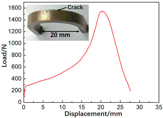
Figure 9.
Results of three-point bending tests conducted on tin bronze/steel bimetallic specimens.
3.2. Microstructure and Properties After Annealing
Figure 10 presents the three-point bending test results of the annealed tin bronze/steel bimetallic material. As the annealing temperature increases, the bending load decreases. Within the annealing temperature range of 300 °C to 700 °C, no delamination is observed between the cladding layer and the steel substrate, and neither the steel substrate nor the cladding layer exhibits any cracks. This suggests that both the cladding layer and the steel substrate exhibit good plasticity, and that a strong interfacial bond exists between the two materials. When the annealing temperature reaches 800 °C, no delamination occurs between the cladding layer and the steel substrate. However, distinct macroscopic cracks were observed on the upper surface of the cladding layer, covering its entire surface. This suggests that at this annealing temperature, the plasticity of the cladding layer was significantly diminished. The comparison of the crack observed in the as-cladded sample versus the crack-free surface after annealing at 300 °C is shown in Figure 11. This further demonstrates that annealing at 300 °C can eliminate the cracks.
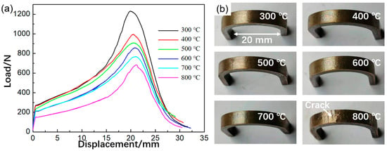
Figure 10.
Three-point bending results of tin bronze/steel bimetallic after annealing: (a) load/displacement curves; (b) morphology of tin bronze/steel bimetallic after bending.
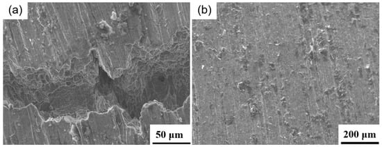
Figure 11.
Comparison of the cracks on the surface of bending sample: (a) without annealing; (b) annealing at 300 °C.
Figure 12a presents the stress-displacement curve of the annealed tin bronze/steel bimetallic material during the shearing process. The data comes from the most representative sample. As the annealing temperature increases, the shear strength gradually decreases. When the annealing temperature reaches 300 °C, the tin bronze cladding layer in the specimen undergoes shear fracture, and the fracture consists of shear dimples (Figure 12b,c), indicating that a ductile fracture mode is present during the shearing process. At annealing temperatures ranging from 400 to 700 °C, the morphology of the shear fracture is similar to that observed at 300 °C; therefore, it is not discussed in further detail in this article.
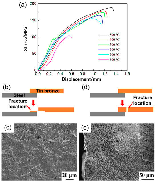
Figure 12.
Shear strength of tin bronze/steel bimetallic after annealing: (a) stress-displacement curve; (b,c) fracture position and morphology of samples annealed at 300 °C; (d,e) fracture position and morphology annealed at 800 °C.
As the annealing temperature increases, the strength of the cladding layer decreases, leading to a slight reduction in the measured shear strength. Following annealing treatment, the tin bronze maintains satisfactory interfacial bonding performance with the steel substrate. When the annealing temperature reached 800 °C, the specimen did not undergo shear fracture, whereas the tin bronze alloy layer experienced tensile fracture, exhibiting an intergranular fracture mode. The dimples on this fracture were relatively shallow (Figure 12d,e). Due to the low strength of the cladding layer, the measured nominal shear strength exhibited a sharp decline.
Figure 13 presents the stress-displacement curves of the tin bronze layer, the steel substrate, and the tin bronze/steel bimetallic material under varying annealing temperatures. Table 4 summarizes the tensile strength and elongation values of the samples. When the temperature ranges from 300 to 700 °C, an increase in the annealing temperature results in a decrease in the strength of the tin bronze layer and an increase in its elongation after fracture (Figure 13a). When the annealing temperature increases to 800 °C, the strength of tin bronze decreases significantly, and the elongation after fracture approaches 0. As the annealing temperature increases, the strength of the steel gradually decreases, whereas its elongation exhibits a continuous increase (Figure 13b). For the tin bronze/steel bimetallic materials, within the temperature range of 300 °C to 700 °C, an increase in temperature results in a decrease in strength, whereas elongation shows a corresponding increase (Figure 13c). The strength and elongation of the bimetallic material after fracture fall between the values corresponding to the steel substrate and tin bronze. When the annealing temperature reaches 800 °C, both the strength and ductility of the bimetallic material exhibit a reduction.
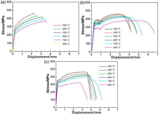
Figure 13.
Stress-displacement curves during tensile processes under varying temperature: (a) tin bronze layer; (b) steel substrate; (c) tin bronze/steel bimetallic.

Table 4.
Tensile strength and elongation of samples at different annealing temperatures.
Figure 14 presents the fracture morphologies of the tin bronze layer under different annealing temperatures. Within the temperature range of 300 to 700 °C, the fractures of the cladding layer consist of equiaxed dimples, indicating that the tin bronze layer underwent ductile fracture following annealing. As the annealing temperature increases, both the size and depth of the dimples progressively increase, suggesting a corresponding enhancement in the plasticity of the tin bronze with rising annealing temperatures.
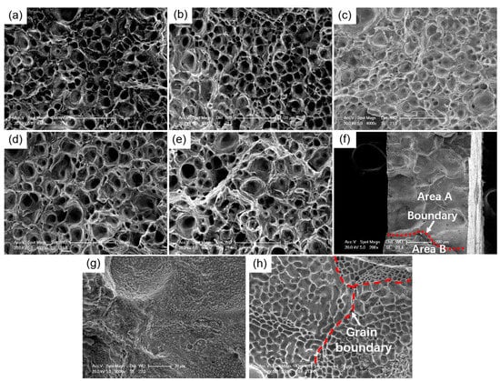
Figure 14.
Fracture morphology of the tin bronze layer at different annealing temperatures: (a) 300 °C; (b) 400 °C; (c) 500 °C; (d) 600 °C; (e) 700 °C; (f) 800 °C; (g) fracture of area A; (h) fracture of area B.
When the temperature reaches 800 °C, the fracture morphology undergoes a transformation, exhibiting an intergranular fracture mode. The intergranular fracture zone can be further classified into two distinct regions, one of which (area A) has undergone oxidation. Upon reaching 800 °C, certain grain boundaries experience melting and react with the surrounding air, resulting in the formation of an oxide film on the fracture. The unmelted region fractures along the coarse grain boundaries, and relatively shallow dimples are observed at these boundaries (area B). Therefore, following annealing at 800 °C, the strength and ductility of tin bronze remain at relatively low levels. The fracture morphology of steel substrates at different annealing temperatures is shown in Figure 15. All steel substrates at different annealing temperatures exhibit ductile fracture. With the increase in annealing temperature, the size and depth of ductile dimples increase, further indicating that the increase in annealing temperature increases the plasticity of steel substrates.
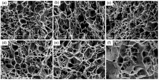
Figure 15.
Fracture morphology of steel substrate at different annealing temperatures: (a) 300 °C; (b) 400 °C; (c) 500 °C; (d) 600 °C; (e) 700 °C; and (f) 800 °C.
Figure 16 presents the hardness distribution of the tin bronze/steel bimetallic material after annealing. Following annealing at 300 °C, the hardness of the tin bronze layer decreased from 111–116 HV prior to annealing to 106–112 HV, while the hardness of the steel layer decreased from 136–146 HV to 128–133 HV. As the annealing temperature increases, the hardness of both the cladding layer and the steel substrate gradually decreases. When the annealing temperature reaches 800 °C, the hardness of the cladding layer decreases to 79–81 HV, and that of the steel substrate decreases to 95–101 HV. The decreasing trends in hardness for both the cladding layer and the steel substrate are generally consistent with the corresponding trends in their tensile strength.
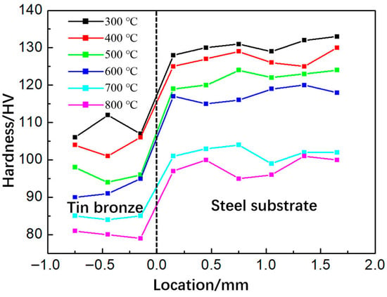
Figure 16.
Effect of annealing temperature on hardness of tin bronze/steel bimetallic materials.
Figure 17 presents the microstructural evolution of the cladding layer at various annealing temperatures. When the annealing temperature reaches 300 °C, evident dendritic segregation remains present within the cladding layer. The δ-Cu41Sn11 phase is observed in the interdendritic regions, with a reduction in its size and partial dissolution into the α-Cu(Sn) matrix. The microstructure following annealing at 400 °C remains largely similar to that observed after annealing at 300 °C, with dendritic segregation still present. A greater amount of the δ-Cu41Sn11 phase has dissolved into the α-Cu(Sn) matrix. When the annealing temperature is increased to 500–600 °C, all δ-Cu41Sn11 phases are completely dissolved into the α-Cu(Sn) matrix. When the annealing temperature reaches 700 °C, dendritic segregation is fully eliminated. Upon further increasing the annealing temperature to 800 °C, grain growth becomes evident in the cladding layer.
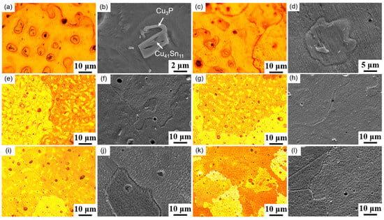
Figure 17.
Effect of annealing temperature on the microstructure of the tin bronze layer: (a,b) 300 °C; (c,d) 400 °C; (e,f) 500 °C; (g,h) 600 °C; (i,j) 700 °C; (k,l) 800 °C.
The effect of annealing temperature on the microstructure of the steel substrate is illustrated in Figure 18. At annealing temperatures ranging from 300 to 400 °C, no significant microstructural changes are observed; the microstructure remains composed of lamellar pearlite, granular cementite, and ferrite. When the annealing temperature is elevated to 500 °C, granular cementite remains largely unchanged, while the amount of lamellar pearlite decreases markedly. Upon further increasing the temperature to the range of 600–700 °C, the lamellar pearlite completely disappears, and the quantity of granular cementite gradually diminishes. At an annealing temperature of 800 °C, only a minimal amount of granular cementite persists within the steel substrate, accompanied by noticeable grain growth.
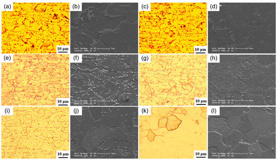
Figure 18.
Effect of annealing temperature on microstructure of steel substrate: (a,b) 300 °C; (c,d) 400 °C; (e,f) 500 °C; (g,h) 600 °C; (i,j) 700 °C; (k,l) 800 °C.
At relatively low temperatures, the diffusion of tin atoms proceeds at a significantly reduced rate. Consequently, a lower annealing temperature is insufficient to fully eliminate the segregation and hard brittle phase within the cladding layer. As the annealing temperature increases, the number of vacancies in the cladding layer rises, thereby increasing the probability that solute atoms acquire sufficient energy to overcome potential barriers and undergo diffusion [30]. Concurrently, the diffusion rate of solute atoms through defects such as dislocations and grain boundaries also increases, facilitating a more uniform microstructural evolution. Hence, temperature exerts a significant influence on the diffusion process. The δ-Cu41Sn11 phase contributes to the enhancement of strength and wear resistance in tin bronze; however, it compromises the material’s plasticity. During annealing at temperatures ranging from 300 to 500 °C, the δ-Cu41Sn11 phase gradually dissolves, leading to a reduction in strength and an improvement in plasticity. When the annealing temperature is elevated to the range of 600–700 °C, segregation is further diminished, the homogenization of the material’s microstructure and composition is enhanced, and the strength continues to decrease. The relief of residual stress and dislocation structure also improve the plasticity and elongation of the tin bronze. Upon annealing at 800 °C, the grains of tin bronze undergo growth, resulting in microstructural coarsening. This coarsening leads to a significant reduction in both the strength and plasticity of tin bronze, thereby deteriorating its overall mechanical properties. Bimetallic materials utilized in the manufacture of bearing shells must exhibit high strength along with sufficient plasticity (ensuring no cracking during 180° bending).
The relationship between annealing temperature (300–800 °C) and all key mechanical parameters (tensile strength, shear strength, hardness, and elongation) for tin bronze/steel bimetallic materials is shown in Figure 19. When the annealing temperature is 300 °C, bimetallic materials have high strength, hardness, and sufficient plasticity. An annealing temperature of 300 °C is deemed an appropriate parameter for achieving the desired mechanical properties. Tin bronze/steel bimetallic is a type of bearing material that is subjected to high-speed and heavy loads in practical working environments. In the future work, fatigue life testing and phase evolution dynamics analysis of tin bronze/steel bimetallic materials will be further systematically studied.
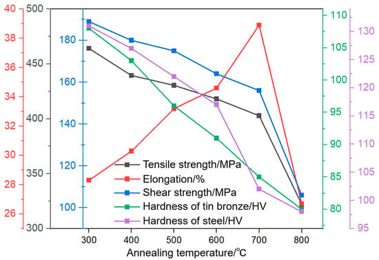
Figure 19.
Annealing temperature and mechanical parameters for tin bronze/steel bimetallic materials.
4. Conclusions
This study investigates the microstructure and properties of tin bronze/steel bimetallic materials fabricated via the arc cladding process, with a focus on examining the effects of the annealing process on these characteristics. The following conclusions have been drawn.
The microstructure of tin bronze comprises three distinct zones: the fine-grained zone, the columnar dendritic zone, and the freely dendritic zone. The dendrites are primarily composed of the α-Cu(Sn) phase. The Sn content is relatively low within the dendritic interiors, whereas it is significantly higher in the dendrite edges and grain boundaries. Additionally, an (α-Cu(Sn) + δ-Cu41Sn11 + Cu3P) ternary eutectic structure is present in the interdendritic regions.
The tin bronze layer exhibits a hardness of 111–116 HV, a tensile strength of 487.0 MPa, and an elongation after fracture of 14.3%. The steel substrate has a hardness of 132–135 HV, a tensile strength of 505.1 MPa, and an elongation after fracture of 29.1%. The bimetallic material demonstrates a tensile strength of 490.1 MPa and an elongation after fracture of 26.6%. The interfacial shear strength between the two metals is measured at 193 MPa, with shear fracture occurring within the tin bronze layer. Furthermore, the tin bronze layer in the bimetallic material exhibited cracking when subjected to a three-point bending test at 180°.
When the annealing temperature ranges from 300 to 700 °C, an increase in temperature leads to the gradual dissolution of the δ-Cu41Sn11 phase into the α-Cu(Sn) matrix, accompanied by a progressive reduction in segregation. Simultaneously, the lamellar pearlite structure in the steel substrate also gradually diminishes. As a result, the tensile strength, shear strength, and hardness of the bimetallic material decrease, while the elongation after fracture increases. The material remains free of cracking when subjected to 180° bending. However, upon reaching an annealing temperature of 800 °C, the overall mechanical performance of the bimetallic material deteriorates rapidly. An annealing temperature of 300 °C is deemed an appropriate parameter for achieving the desired mechanical properties.
Author Contributions
Z.Y.: Conceptualization, methodology and investigation; C.C.: Data curation and Supervision. All authors have read and agreed to the published version of the manuscript.
Funding
This research was funded by the Natural Science Foundation of the Jiangsu Higher Education Institutions of China, grant number 24KJD430010.
Data Availability Statement
The original contributions presented in the study are included in the article; further inquiries can be directed to the corresponding author.
Acknowledgments
The authors thank the teachers at the Jiangsu Intelligent Production Line Technology and Equipment Engineering Research Center for the help of experiments.
Conflicts of Interest
The authors declare no conflicts of interest.
References
- Wang, Z.; Huo, D.; Sun, Y.; Li, Y.; Zhou, R.; Li, Z.; Liu, Z. Unveiling ultra-high plasticity and the mechanism of microstructural evolution in semi-solid squeeze-cast leaded nickel-tin bronze through solution treatment. Mater. Charact. 2025, 229, 115521. [Google Scholar] [CrossRef]
- Jin, X.; Hou, J.; Chen, Z. Research on the influence of titanium addition on the structure and frictional performance of laser clad tin bronze coating. J. Laser. Appl. 2025, 37, 012008. [Google Scholar] [CrossRef]
- Wang, Y.; Xu, L.; Li, X. Tribological Properties of Cu-Based Self-Lubricating Materials Composed with Cu- or Ni-Plated Graphite. Lubricants 2023, 11, 271. [Google Scholar] [CrossRef]
- Marklund, P.; Berglund, K.; Larsson, R. The influence on boundary friction of the permeability of sintered bronze. Tribol. Lett. 2008, 31, 1–8. [Google Scholar] [CrossRef]
- Kostornov, A.G.; Fushchich, O.I.; Chevichelova, T.M. Structurization in sintering of antifriction powder materials based on iron-copper alloys. Powder Metall. Met. Ceram. 2007, 46, 589–594. [Google Scholar] [CrossRef]
- Santos, C.A.; Spim, J.A.; Garcia, A. Modeling of solidification in twin-roll strip casting. J. Mater. Process. Tech. 2000, 102, 33–39. [Google Scholar] [CrossRef]
- Kim, J.U.; Shojaee, M.; Sherepenko, O.; Ramachandran, D.; Betiku, O.T.; Midawi, A.R.H.; Ghassemi-Armaki, H.; Biro, E. Half-sectioned spot weld parameter optimisation for liquid metal embrittlement analysis in advanced high-strength steels. Sci. Technol. Weld. Join. 2024, 29, 61–69. [Google Scholar] [CrossRef]
- Xiao, P.; Wang, L.; Tang, Y.; Tu, X.; Song, X.; Chen, L.; Liu, F.; Zhang, Y. Effect of wire composition on microstructure and penetration crack of laser-cold metal transfer hybrid welded Cu and stainless steel joints. Mater. Chem. Phys. 2023, 299, 127480. [Google Scholar] [CrossRef]
- Sage, D.; Fink, C. Understanding temperature and dwell time dependence of liquid metal embrittlement in austenitic stainless steel by liquid zinc and copper. Materialia 2022, 24, 101502. [Google Scholar] [CrossRef]
- Chen, C.; Li, W.; Tu, F.; Qin, T. Effect of Heat Input on Tin Bronze-Induced Intergranular Cracks During Arc Cladding. Crystals 2024, 14, 926. [Google Scholar] [CrossRef]
- Zhu, Y.; Wang, H.; Wang, Y.; Hao, Y.; Lu, F. Formation mechanism of liquid metal embrittlement in laser lap welding of zinc-coated GEN3 steels. Mater. Sci. Eng. A 2021, 800, 140229. [Google Scholar] [CrossRef]
- Wang, S.; Chen, C.; Ju, J.; Zhou, J.; Xue, F. Effect of Al Bronze Interlayer on Liquid-Solid Compound Interface of Sn Bronze/Steel. Adv. Eng. Mater. 2023, 25, 2201227. [Google Scholar]
- Arias-Gonzalez, F.; Del Val, J.; Comesana, R.; Penide, J.; Pou, J. Laser cladding of phosphor bronze. Surf. Coat. Tech. 2017, 313, 248–254. [Google Scholar] [CrossRef]
- Zhao, L.; Li, J.; Yang, Q.; Wang, Y.; Zhang, X.; Li, H.; Yang, Z.; Xu, D.; Liu, J. Study on Friction and Wear Properties of New Self-Lubricating Bearing Materials. Crystals 2022, 12, 834. [Google Scholar] [CrossRef]
- Evangeline, A.; Sathiya, P. Cold metal arc transfer (CMT) metal deposition of Inconel 625 superalloy on 316L austenitic stainless steel: Microstructural evaluation, corrosion and wear resistance properties. Mater. Res. Express 2019, 6, 066516. [Google Scholar] [CrossRef]
- Wei, M.; Sun, K.; Zhang, X.; Zhang, C.; Chen, Z.; Zhou, J.; Xue, F. Microstructure and bonding strength of tin-based Babbitt alloy on ASTM 1045 steel by MIG arc brazing. J. Adhes. Sci. Technol 2018, 32, 2150–2160. [Google Scholar] [CrossRef]
- Chen, C.; Zhao, J.; Zhou, J.; Xu, F. Arc deposited AlSi12 cladding layer on steel plate without zinc coating. Mater. Sci. Tech. 2020, 36, 100–107. [Google Scholar] [CrossRef]
- Chen, J.; Yang, Y.; Song, C.; Zhang, M.; Wu, S.; Wang, D. Interfacial microstructure and mechanical properties of 316L/CuSn10 multi-material bimetallic structure fabricated by selective laser melting. Mater. Sci. Eng. A 2019, 752, 75–85. [Google Scholar] [CrossRef]
- Zhang, H.; Jiao, K.; Zhang, J.; Liu, J. Comparisons of the microstructures and micro-mechanical properties of copper/steel explosive-bonded wave interfaces. Mater. Sci. Eng. A 2019, 756, 430–441. [Google Scholar] [CrossRef]
- Liac, X.; Ivas, T.; Spierings, A.; Wegener, K.; Leinenbach, C. Phase and microstructure formation in rapidly solidified Cu-Sn and Cu-Sn-Ti alloys. J. Alloys Compd. 2018, 735, 1374–1382. [Google Scholar]
- Chen, C.; Zhou, J.; Yu, J.; Ju, J.; Zhang, Y.; Wang, J.; Fan, B. Interfacial microstructures and infiltrated cracks in tin bronze/steel bimetallic materials fabricated by arc cladding. J. Mater. Sci. 2023, 58, 4679–4693. [Google Scholar] [CrossRef]
- Chen, C.; Sun, K.; Zhao, J.; Zhou, J.; Xue, F. Effect of current on microstructures and properties of tin bronze/steel bimetallic sheets fabricated by arc deposited technique. Mater. Res. Express. 2019, 6, 126534. [Google Scholar] [CrossRef]
- Song, Q.; He, M.; Li, T.; Han, J.; He, C.; Guo, X.; Feng, G.; Xiong, L. Design and mechanism research of online control and monitoring system for laser welding quality. Mater. Des. 2025, 259, 114849. [Google Scholar] [CrossRef]
- Valloton, J.; Wagniere, J.D.; Rappaz, M. Competition of the primary and peritectic phases in hypoperitectic Cu-Sn alloys solidified at low speed in a diffusive regime. Acta. Mater. 2012, 60, 3840–3848. [Google Scholar] [CrossRef]
- Asadian, M.; Zabihi, F.; Saeedi, H. Segregation and constitutional supercooling in Nd:YAG Czochralski crystal growth. J. Cryst. Growth 2024, 630, 127605. [Google Scholar] [CrossRef]
- Wang, Z.; Zhou, R.; Li, Y.; Sun, Y.; Huo, D.; Zhang, H.; Li, Y.; Li, Z. Synergistic enhancement of strength and ductility in leaded nickel-tin bronze by constructing a core-rim dual-phase microstructure via semi-solid squeeze casting. Mater. Sci. Eng. A 2025, 944, 148902. [Google Scholar] [CrossRef]
- Liang, Y.; Jiang, H.; Lei, Q.; Jiang, L.; Zhang, X.; Xiao, S.; Liu, X.; Li, L.; Pei, Z.; Li, Q. Cr3C2 reinforced tin-bronze matrix composites with enhanced mechanical properties and wear resistance. Mater. Charact. 2024, 210, 113805. [Google Scholar] [CrossRef]
- Peng, B.; Jie, J.; Wang, M.; Dong, B.; Wang, X.; Li, S.; Li, T. Microstructure characteristics and deformation behavior of tin bronze/1010 steel bimetal layered composite by continuous solid/liquid bonding. Mater. Sci. Eng. A 2022, 844, 143155. [Google Scholar] [CrossRef]
- Ding, F.; Zhang, T.; Wang, C.; Sui, J.; Zhu, X.; Gao, K. Mechanism of chip segmentation transition from shear slip to shear fracture of Zirconium-based bulk metallic glass in mechanical machining. J. Mater. Res. Technol. 2024, 30, 7398–7412. [Google Scholar] [CrossRef]
- Zhang, H.; Ma, Z.; Li, C.; Yuan, H.; Cheng, X. Solute-vacancy complexes govern Cu diffusion anisotropy in β-Sn: Insights from first-principles and experiments. Mater. Today Commun. 2025, 48, 113364. [Google Scholar] [CrossRef]
Disclaimer/Publisher’s Note: The statements, opinions and data contained in all publications are solely those of the individual author(s) and contributor(s) and not of MDPI and/or the editor(s). MDPI and/or the editor(s) disclaim responsibility for any injury to people or property resulting from any ideas, methods, instructions or products referred to in the content. |
© 2025 by the authors. Licensee MDPI, Basel, Switzerland. This article is an open access article distributed under the terms and conditions of the Creative Commons Attribution (CC BY) license (https://creativecommons.org/licenses/by/4.0/).