Article

Terahertz Dielectric Metasurface for Reconfigurable Multifunctional Holographic Dual-Mode Imaging Controlled by Graphene

School of Electronic and Information Engineering, South China University of Technology, Guangzhou 510640, China
*
Author to whom correspondence should be addressed.
Crystals 2024, 14(8), 713; https://doi.org/10.3390/cryst14080713
Submission received: 24 July 2024 / Revised: 2 August 2024 / Accepted: 7 August 2024 / Published: 8 August 2024
(This article belongs to the Section Hybrid and Composite Crystalline Materials)

Abstract

:
Metasurfaces are considered the most promising technologies for holographic imaging applications due to their exceptional optical properties and capabilities. However, the work on terahertz (THz) metasurface holographic imaging is relatively limited. Here, we propose a THz dielectric geometric-propagation phase metasurface that can operate in dual modes (reflection and transmission) and enable reconfigurable multifunctional holographic imaging. The dual-mode operation is realized by controlling the Fermi energy level (Ef) of the graphene integrated into the metasurface unit, and the reconfigurable three-channel holographic imaging in reflection or transmission mode are achieved by switching the feed polarization among left-handed circular polarization (LCP), right-handed circular polarization (RCP), and linear polarization (LP). The metasurface is designed based on the transmission mode, and a physical model for switching to the reflection mode is established. For the first time, to the best of our knowledge, a reflection–transmission dynamic modulation THz holographic imaging metasurface has been developed. The holographic metasurface operates in transmission mode at Ef = 0.1 eV and in reflection mode at Ef = 0.9 eV. Compared with recently published holographic imaging metasurfaces, the proposed metasurface offers the following advantages: high holographic efficiencies (42.5% to 49%), more holographic imaging channels, dynamic modulation dual-mode operations, and reconfigurability. The simulation results match the theory.

1. Introduction

Holography is an advanced imaging technology where image information can be reconstructed without a lens. It is an important tool for controlling wave fields and producing highly complex and customized field distributions. Since its invention, holography has been widely used to record and reconstruct all the information of an object and has found applications in medical observation, virtual reality displays, sensing, data storage, security, secure printing [1,2], and secret sharing [3]. Recently, multiplexing techniques have been widely adopted to realize multiple holographic images or functionalities to increase the information capacity and make the optimum use of the space-bandwidth product. Particularly, with the advancement of computer-generated holograms, hologram generation can be achieved in an easier way through programming.
Metasurfaces are capable of manipulating electromagnetic fields at the subwavelength scale and enabling holographic displays with higher resolution, wider field of view, and smaller geometry size [4]. Since the introduction of a plasmonic metasurface for holography generation in 2013, metasurface-based holography has emerged as a vibrant research field [5]. Holographic multiplexing metasurfaces can record multiple images within the same spatial area, which increase information capacity while maintaining an ultrasmall footprint, subwavelength resolution, and larger field of view [6,7,8,9,10,11,12,13]. Numerous studies have been conducted across various frequency bands, including the near-IR, mid-IR, and visible spectrum. These studies include the following: a single-layer low-pass (LP) metasurface that independently projects distinct holographic images in both transmission and reflection modes at a single frequency [6]. A single-layer transmission metasurface capable of generating multi-channel grayscale images by separately and independently controlling the amplitude and phase [7]; a tri-channel single-layer transmission metasurface that simultaneously records a continuous grayscale nanoprinting image in the near field and projects two independent holographic images in the far field [8]; an all-dielectric transmission single-layer metasurface that generates polarization-multiplexed holographic images [9]. Significant advancements have also been achieved in the microwave frequency band: a single-layer reflective metasurface generating four-channel holographic images by simultaneous frequency and polarization multiplexing at 7.5 GHz and 13 GHz [10], a frequency-multiplexed single layered transmission metasurface for four-channel holography images at 7.2 GHz, 9.1 GHz, 10.9 GHz, and 15.2 GHz [11], a full-space single-layer encoding metasurface independently manipulating the images ‘F’ and ‘H’ in transmission or reflection mode based on polarization multiplexing at 10 GHz [12], reconfigurable holographic images achieved by switching the transmission metasurface shape from planar (for the letter ‘Z’ image, 14.8–15.0 GHz) to zigzag (for the letter ‘L’ image, 14.8–15.2 GHz) [13].
Terahertz (0.1–10 THz) wireless communication is a cornerstone of the next 6G wireless. THz frequencies have the potential to dramatically increase wireless capacity performance and enable high-resolution environment sensing. THz waves can penetrate substances that are opaque to visible and infrared light and possess higher spatial resolution, penetration depth, and non-ionization safety. However, the research on THz metasurface holography images is still in its nascent stages. Reference [14] reported single-pixel THz near-field imaging, achieving a λ0/45 resolution at 0.75 THz and a λ0/133 resolution at 0.5 THz. In reference [15], single-pixel computational ghost imaging with reflective multilayer metasurface holography was introduced in an optical encryption scheme. A reconfigurable and multifunctional 3-bit coding reflection single-layer metasurface at 0.95 THz is proposed by integrating photosensitive Ge material into the metasurface unit. By controlling the photosensitive germanium material under right circularly polarized (RCP) incidence, switching between vortex beams and holographic imaging is achieved [16]. A multilayer metasurface achieved reconfigurable multichannel holographic imaging in the THz band by integrating vanadium dioxide (VO2) into the metasurface unit [17]. The holographic letters ‘R’ and ‘L’ were achieved when the temperature was above 68 °C, and the holographic numbers ‘2’ and ‘6’ were generated in the other two channels when metalen’s temperature was below 68 °C.
Graphene has garnered extensive research attention due to its mechanical robustness, outstanding thermal stability, and chemical and biological stability. Reconfigurable multi-channel-reflected light beams were obtained by integrating graphene into the metasurface unit cell [18]. A multifocal graphene orbital angular momentum (OAM) metalen was designed using spatially multiplexed single-focus with different focal lengths and topological charges [19].
As mentioned above, multi-channel holographic multiplexing images have been realized using transmission, reflection, or transmission–reflection mode metasurface. Full-space meta-holograms offer the advantages of miniaturization and high integration. However, to the knowledge of the authors, the above full space metasurface is realized by controlling orthogonal linearly polarized waves, and there is no dynamic modulation of dual modes (transmission and reflection) based on phase change material. In the THz frequency band, there is no reflection–transmission dual mode metasurface for holographic imaging, and there is no dynamic modulation holographic imaging based on graphene. Here, a reflection–transmission dynamic modulation THz single-layer propagation-geometric phase dielectric metasurface is proposed, based on graphene. The reflection and transmission modes can be switched by controlling the Fermi energy level of graphene integrated into the metasurface unit. In the meantime, the metasurface is also reconfigurable in reflection or transmission mode by switching the feed polarization among RCP, LCP, and LP. As an example, a reflection and transmission propagation–geometric phase metasurface is designed, and reconfigurability between reflection and transmission modes is achieved by switching the graphene Fermi energy level between 0.1 eV and 0.9 eV. It consists of three layers: an indium telluride pillar unit layer (top), an F4B substrate (middle), and a graphene layer (bottom). The operation bandwidth for the reflection mode is from 1.15 THz to 1.35 THz (16%) and from 1.32 THz to 1.6 THz (19%) for the transmission mode. Figure 1a,b show high holographic efficiencies (42.5% to 49%), and a six-channel holographic imaging is obtained. In view of the fabrication difficulties and testing environment limitations, this article is restricted to theoretical predictions and simulation results, which exhibit satisfactory agreement.

2. Materials and Methods

Figure 1 shows the schematic diagram for the dual mode reconfigurable multifunctional metasurface, which consists of three layers: an indium telluride pillar unit layer (top), an F4B substrate (middle), and a graphene layer (bottom). Figure 1 shows the reconfigurable holographic imaging obtained by switching the incidence polarization in reflection and transmission modes, respectively. Figure 1c is the phase switching sketch map: metal when Ef = 0.9 eV, insulator when Ef = 0.1 eV. The proposed metasurface works in reflection and transmission modes when Ef = 0.9 eV and 0.1 eV, respectively. The reconfiguration among the Chinese characters ‘Crystals 14 00713 i001’, ‘Crystals 14 00713 i002’, and ‘Crystals 14 00713 i003
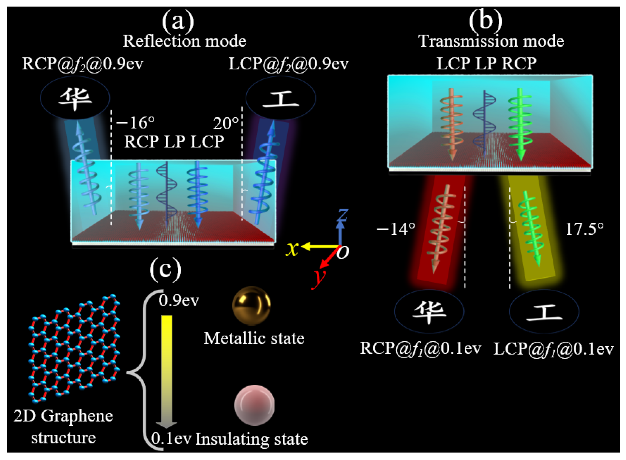
’ is achieved by switching LCP, RCP, and LP incidences, respectively. The operation frequency range is 1.15–1.35 THz (16%) for the reflection mode, and 1.32–1.6 THz (19%) for the transmission mode. The holographic imaging is co- and cross-polarization for reflection and transmission modes, respectively.

2.1. Phase Change Principle of Graphene

The electric conductivity of graphene is the sum of inter-band and intra-band conductivity according to the Kubo equation. The inter-band conductivity can be neglected at room temperature in the lower THz frequency band, and the surface electric conductivity σg(ω) of graphene is described as follows [20]:
σ g ω σ intra ω = j e 2 K B T π 2 ω + j τ 1 E f K B T + 2 I n e x p E f K B T + 1
where ω, e, KB, T, , τ, and Ef are the angular frequency, electron charge, Boltzmann constant, environmental temperature, Planck’s constant, the relaxation time, and the Fermi energy level, respectively. The letter j is the imaginary unit. The conductivity of graphene can be continuously tuned by manipulating its Fermi energy via extra voltage. Graphene functions as the dielectric when Ef = 0.1 eV, and is in a metallic state when Ef = 0.9 eV [21]. Here, set τ = 1 ps and T = 300 K. The conductivity of graphene is a function of ω and Ef, according to Equation (1). In this paper, the proposed reconfigurable metasurface works in transmission mode at frequency f1 when Ef = 0.1 eV, and in reflection mode at frequency f2 when Ef = 0.9 eV. The metallic 2D graphene layer acts as ground plane in reflection mode.

2.2. The Phases (ϕx, ϕy, β) Calculation Principle for Geometry–Propagation Phase Unit

After the phase distribution map for the metasurface is calculated according to the Gerchberg–Saxton (GS) algorithm, a unit with phase parameters (ϕx, ϕy, β) is designed to implement the calculated phase distribution map. The physical model of the unit phase (ϕx, ϕy, β) vs. the outgoing wave phase is as follows:
When a unit with x-axis or y-axis symmetry is rotated by an angle β in the xoy plane, and a propagation–geometric phase metasurface unit is formed.
For transmission metasurface, assume the transmission amplitude tx(y) for x- or y-polarization approaches 1. When the transmission metasurface is excited by the normal CP incidence plane wave, the co-polarized (Jco) and cross-polarized (Jcross) components are given by the following [19]:
J c o = 1 2 e i ϕ x + e i ϕ y = cos ϕ x ϕ y 2 × e i ϕ x + ϕ y 2 J c r o s s = 1 2 e i ϕ x e i ϕ y × e i 2 β × σ ^ R + e i 2 β × σ ^ L = sin ϕ x ϕ y 2 × e i ϕ x + ϕ y + π 2 × e i 2 β × σ ^ R + e i 2 β × σ ^ L
where σ ^ R = 1 2 1 i i 1 and σ ^ L = 1 2 1 i i 1 are defined as polarization operators, and the subscripts L and R represent LCP and RCP, respectively. ϕx and ϕy are the propagation phases for x- and y-polarization, respectively. β is the rotated angle in the xoy plane. From Equation (2), the amplitude (t) and phase (ϕ) for Jco and Jcross are as follows:
t c o = cos ( ϕ x ϕ y ) / 2 t c r o s s = sin ( ϕ x ϕ y ) / 2
ϕ c o = ( ϕ x + ϕ y ) / 2 ϕ c r o s s = ( ϕ x + ϕ y + π ) / 2 ± 2 β
From Equation (4), the phase for the cross-dual CP can be independently controlled as follows: ϕ c r o s s R C P = ( ϕ x + ϕ y + π ) / 2 + 2 β for RCP, ϕ c r o s s L C P = ( ϕ x + ϕ y + π ) / 2 2 β for LCP. If ϕ x = ϕ y + π , the co-polarized component is suppressed according to Equation (2), and the metasurface converts RCP (LCP) incident waves to outgoing LCP (RCP) waves. Then, the propagation phase and rotation angle of the unit can be derived as described by Equation (4):
ϕ x = ϕ y + π ϕ y = ( ϕ c r o s s R C P + ϕ c r o s s L C P 2 π ) / 4 β = ( ϕ c r o s s R C P ϕ c r o s s L C P ) / 4
For the reflection metasurface, assume the reflection amplitudes for x- or y-polarization are unity (rx = ry = 1) and that (ϕxϕy = π). When the reflection metasurface is excited by a normal CP incidence plane wave, the Jones matrix of the outgoing wave is as follows [22,23]:
E L L r E R R r = C M J M 1 C 1 = e ( ϕ x i 2 β ) 0 0 e ( ϕ x + i 2 β ) E L i E R i
where ELi, ELLr, ELLr, and ERRr represent the incident LCP wave, the incident RCP wave, the LCP outgoing wave, and the RCP outgoing wave, respectively. M = cos β sin β sin β cos β , J = e j ϕ x 0 0 e j ϕ y , C = 1 2 1 i 1 i , and C = 1 2 1 i 1 i . The cross-polarized component is suppressed, and the outgoing wave is co-polarized. The co-polarization phases for LCP and RCP waves are as follows:
ϕ c o L C P = ϕ x 2 β ϕ c o R C P = ϕ x + 2 β

2.3. Gerchberg–Saxton Algorithm

The GS algorithm, which was originally proposed by D. Gerchberg and W. Saxton in 1972 [24], is an iterative algorithm commonly used in phase retrieval for holographic imaging based on Fourier transform and inverse Fourier transform. The iteration starts from the measured amplitude information of the input image, and continues until the error threshold ( E i E 0 ) < ε is met. Here, the GS algorithm is used to obtain the phase distribution map of the phase gradient metasurface, and the basic steps and method are shown in Figure 2.
The required images ‘Crystals 14 00713 i004’, ‘Crystals 14 00713 i005’, in z-axis direction are established by computer holography technology based on MATLAB 2022. First, painting software is used to draw the required images (including the black background and the white images). Second, the amplitude matrix A0 (m × n) in the image area is obtained by the MATLAB function ‘imread’ and ‘binary’. In A0 (m × n), the intensities are “1” and “0” for points (x, y, 0) in white and black, respectively. Third, the MATLAB function ‘random’ generates a random phase matrix ΦGS0 (m × n). Apply Fourier transform to the matrices A0 and ΦGS0 and obtain the amplitude and phase matrices in the frequency domains A1 and ΦGS1. Then, update all the amplitude matrix values in A1 (m × n) to 1; that is, A′1 (x, y) = 1. Perform the inverse Fourier transform on A′1 and ΦGS1 and obtain the amplitude and phase matrices in the time domains A2 and ΦGS2. Repeat the iterative operations of step 2 and step 3 and update the i-th iteration amplitude Ai (x, y) to AI (x, y) = 1 until the error threshold ( E i E 0 ) < ε , where E = A exp ( i ϕ G S ) . Then, the phase distribution map for the metasurface is obtained.

2.4. The Total Compensated Phase Calculation Based on Transmission Mode

The metasurface is designed in transmission mode at f1 when Ef = 0.1 eV. Under LCP incidence, a holographic imaging RCP ‘Crystals 14 00713 i006’ is generated in the direction (θ1, 0°). Under RCP incidence, a holographic imaging LCP ‘Crystals 14 00713 i007’ is generated in the direction (θ2, 0°). The phase compensation for the metasurface obtained by GS algorithm is ΦGS, which is for the images in normal direction. An additional compensated phase is added for the desired imaging direction (θ, 0°), and the compensated phase for RCP ‘Crystals 14 00713 i008’ or LCP ‘Crystals 14 00713 i009’ for the metasurface unit located at (x, y, 0) is as follows:
Crystals 14 00713 i010
Then, the compensated phase parameters (ϕx, ϕy, β) of the metasurface unit for the reconfigurable multifunctional holographic imaging for ‘Crystals 14 00713 i011’, ‘Crystals 14 00713 i012’, and ‘Crystals 14 00713 i013’ are calculated by Equations (5) and (8).

2.5. The Imaging Direction Deduction for Reflection Mode

By switching the bottom graphene layer from insulator to metal states, the metasurface designed in transmission mode can be made to work in reflection mode with the bottom graphene layer acting as a ground plane. According to Equation (6), the holographic imaging of (RCP, ‘Crystals 14 00713 i014’, θ1, 0°) and (LCP, ‘Crystals 14 00713 i015’, θ2, 0°), designed in the transmission mode, has changed into the co-polarized imaging of (LCP, ‘Crystals 14 00713 i016’, θ3, 0°) and (RCP, ‘Crystals 14 00713 i017’, θ4, 0°) in the reflection mode, as shown in Figure 3. Though the phase distribution map of the metasurface is calculated based on the transmission mode, (LCP, ‘Crystals 14 00713 i018’, θ3, 0°) and (RCP, ‘Crystals 14 00713 i019’, θ4, 0°) are generated under LCP and RCP incidences in reflection mode, respectively. Because the graphene permittivity is a function of its state, the operation frequency f2 and direction θ3(4) for the reflection mode are different from f1 and θ1(2) in the transmission mode. The direction θ3(4) is calculated as follows:
Crystals 14 00713 i020
From Equations (8) and (9), θ3 and θ4 are deduced as follows:
θ 3 = arcsin f 1 f 2 sin θ 2 θ 4 = arcsin f 1 f 2 sin θ 1
In summary, based on the above analysis, the proposed metasurface can be switched between the transmission and reflection modes, and the holographic imaging can be reconfigured by switching the incident polarization when operating in transmission or reflection mode. Six holographic imaging channels are achieved, as shown in Table 1.

2.6. Unit Cell Design

The proposed dual-mode metasurface is excited by normal plane wave, as shown in Figure 1 and Figure 3. Open boundaries were set as boundary conditions. As an example, dual-mode reconfigurable multifunctional holographic imaging is designed in order to validate the above design method. (1) Reconfigurable Chinese characters with cross-polarization in transmission mode are achieved when Ef = 0.1 eV: (a) (RCP, ‘Crystals 14 00713 i029’, −14°, 0°), (b) (LCP, ‘Crystals 14 00713 i030’, 17.5°, 0°), and (c) both (RCP, ‘Crystals 14 00713 i031’, −14°, 0°) and (LCP, ‘Crystals 14 00713 i032’, 17.5°, 0°) are achieved by switching between LCP, RCP, and LP incidences, respectively. (2) Reconfigurable multifunctional holographic imaging (Chinese characters) with co-polarization are achieved in reflection mode when Ef = 0.9 eV: (a) (RCP, ‘Crystals 14 00713 i033’, −16°, 0°), (b) (LCP, ‘Crystals 14 00713 i034’, 20°, 0°), (c) both (RCP, ‘Crystals 14 00713 i035’, −16°, 0°) and (LCP, ‘Crystals 14 00713 i036’, 20°, 0°), achieved by switching between the RCP, LCP, and LP incidences, respectively. All the curves and field patterns are simulated by CST Microwave Studio software (version 2020).
To realize the designed dual-mode reconfigurable multifunctional holographic imaging, a unit cell is proposed to implement the phase (ϕx, ϕy, β) at (x, y, 0) calculated by Equation (5), which is shown in Figure 4. Figure 4a–c show the simulation Floquet model, top and side views of the unit, respectively, which consists of a star-shaped indium telluride pillar (εr = 19, tan δ = 0.001) in the top view and a 2D bottom graphene layer separated by an F4B substrate with a dielectric constant 2.2, tan δ = 0.003. All geometry parameters are marked in Figure 4, and the optimized parameters are as follows: p = 123 μm, w = 11 μm, h1 = 150 μm, h2 = 0.5 μm, and h3 = 0.05 μm. The propagation phases ϕx and ϕy are controlled by lx and ly, respectively, and the geometry phase is controlled by rotating the unit cell counterclockwise by β degrees.
We studied the reflection magnitude S11 and the transmission magnitude S21 of the metasurface in both reflection and transmission states. We also provided the impact of the metasurface’s dimensional changes on these two coefficients. Under normal x- and y-polarized incident excitation: (1) For the reflection mode at 1.31 THz, 1.325 THz, and 1.336 THz, Figure 5a shows the simulated S11 and phase ϕx(y) as functions of lx(y), while Figure 5b shows the simulated S11 and phase ϕy(x) as functions of lx(y). (2) For the transmission mode at 1.455 THz, 1.465 THz, and 1.473 THz, Figure 5c shows the simulated amplitude (S21) and phase ϕx(y) curves as functions of lx(y), while Figure 5d is the simulated amplitude (S21) and phase ϕy(x) curves as functions of lx(y). For both the transmission and reflection modes, when lx(y) varies from 15 μm to 113 μm: (1) The phase of the co-polarization ϕx(y) increases from −450° to −90°, covering a 360o phase range. (2) The phase shift of the cross-polarization ϕy(x) remains basically unchanged, indicating that ϕx and ϕy can be independently adjusted by lx and ly, respectively. S11 > 0.99 for the reflection mode, and S21 > 0.85 for the transmission mode. The phase ϕx(y) curves versus lx(y) for different frequency points (at 1.31 THz and 1.325 THz for the reflection mode or at 1.455 THz, 1.465 THz, and 1.473 THz for the transmission mode) are parallel, indicating that the metasurface can operate within a certain bandwidth. According to Figure 5a,c, a polynomial formula for the relationship between ϕx(y) and lx(y) can be fitted as follows:
ϕ x ( y ) = 392.7 × sin ( 0.027 × l x ( y ) + 0.2954 ) + 264.3 × sin ( 0.075 × l x ( y ) + 0.1413 ) + 209.3 × sin ( 0.08 × l x ( y ) + 2.699 )
When lx = 15 μm, Figure 6 shows the curves of the geometric phase as a function of the rotation angle β for the reflection mode when lx = 15 μm (at 1.31 THz, 1.325 THz, and 1.336 THz) and transmission mode (at 1.455 THz, 1.465 THz, and 1.473 THz). When β ranges from 0° to 180°, the geometric phase shift covers 360°, and the geometric phase vs. the β curves at different frequency points (1.31 THz, 1.325 THz, and 1.336 THz for the reflection mode or 1.455 THz, 1.465 THz, and 1.473 THz for the transmission mode) are parallel.

2.7. Metasurface Design

The transmission–reflection reconfigurable metasurface shown in Figure 3 is formed by the proposed 91 × 91 unit cells with the size 11.193 mm × 11.193 mm × 0.15 mm (50.4λ0 × 50.4λ0 × 0.68λ0) for dual-mode reconfigurable multifunctional holographic imaging: (1) reconfigurable cross-polarized holographic imaging in transmission mode when Ef = 0.1 eV: (a) (RCP, ‘Crystals 14 00713 i037’, −14°, 0°), (b) (LCP, ‘Crystals 14 00713 i038’, 17.5°, 0°), and (c) both (RCP, ‘Crystals 14 00713 i039’, −14°, 0°) and (LCP, ‘Crystals 14 00713 i040’, 17.5°, 0°), achieved by switching LCP, RCP, and LP incidences, respectively. (2) Reconfigurable multifunctional co-polarized holographic imaging in reflection mode when Ef = 0.9 eV: (a) (RCP, ‘Crystals 14 00713 i041’, −16°, 0°), (b) (LCP, ‘Crystals 14 00713 i042’, 20°, 0°), (c) both (RCP, ‘Crystals 14 00713 i043’, −16°, 0°) and (LCP, ‘Crystals 14 00713 i044’, 20°, 0°), achieved by switching the RCP, LCP, and LP incidences, respectively.
The compensated phase distributions for ϕx, ϕy, and 2β, according to Equation (5), are shown in Figure 7, and then the corresponding geometry length distributions for lx and ly in the metasurface are obtained according to Equation (11).

3. Results

3.1. 2D and 3D Far-Field Properties

The far-field radiation patterns at 1.325 THz or 1.465 THz under LCP, RCP, and LP incidence are shown in Figure 8. Figure 8a,b show the three-dimension (3D) and 2D far-field radiation patterns for reflection and transmission modes, respectively. Reconfigurable cross-polarized holographic imaging is achieved at 1.465 THz in transmission mode among (‘Crystals 14 00713 i045’, RCP, θ = −14°, φ = 0°), (‘Crystals 14 00713 i046’, LCP, θ = 17.5°, φ = 0°), and both (‘Crystals 14 00713 i047’, RCP, θ = −14°, φ = 0°) and (‘Crystals 14 00713 i048’, LCP, θ = 17.5°, φ = 0°), achieved by switching LCP, RCP, and LP incidences, respectively. Reconfigurable multifunctional co-polarized holographic imaging is achieved at 1.325 THz in reflection mode among (‘Crystals 14 00713 i049’, RCP, θ = −16°, φ = 0°), ‘Crystals 14 00713 i050’, LCP, θ = 20°, φ = 0°), and both (‘Crystals 14 00713 i051’, RCP, θ = −16°, φ = 0°) and (‘Crystals 14 00713 i052’, LCP, θ = 20°, φ = 0°), achieved by switching the RCP, LCP, and LP incidences, respectively. The simulated and calculated holographic imaging are in good agreement. Because LP wave can be decomposed into two equal LCP and RCP waves, both the LCP and RCP excitation are performed simultaneously, and the holographic imaging for the LP incidence is the holographic imaging sum of the LCP and RCP incidences.

3.2. Analysis of the Bandwidth Characteristics

The simulated 3D and 2D far-field holographic imaging with co-polarization under RCP and LCP incidences in reflection mode at 1.15 THz, 1.25 THz, and 1.35 THz are shown in Figure 9a. The profile remains unchanged across different frequencies, indicating an operation bandwidth from 1.15 THz to 1.35 THz (16%). Figure 9b illustrates the simulated 3D and 2D far-field holographic imaging with cross-polarization under the RCP and LCP incidences in the transmission mode at 1.32 THz, 1.465 THz, and 1.6 THz. The profile remains nearly unchanged across different frequencies, indicating an operation bandwidth from 1.32 THz to 1.6 THz (19%).

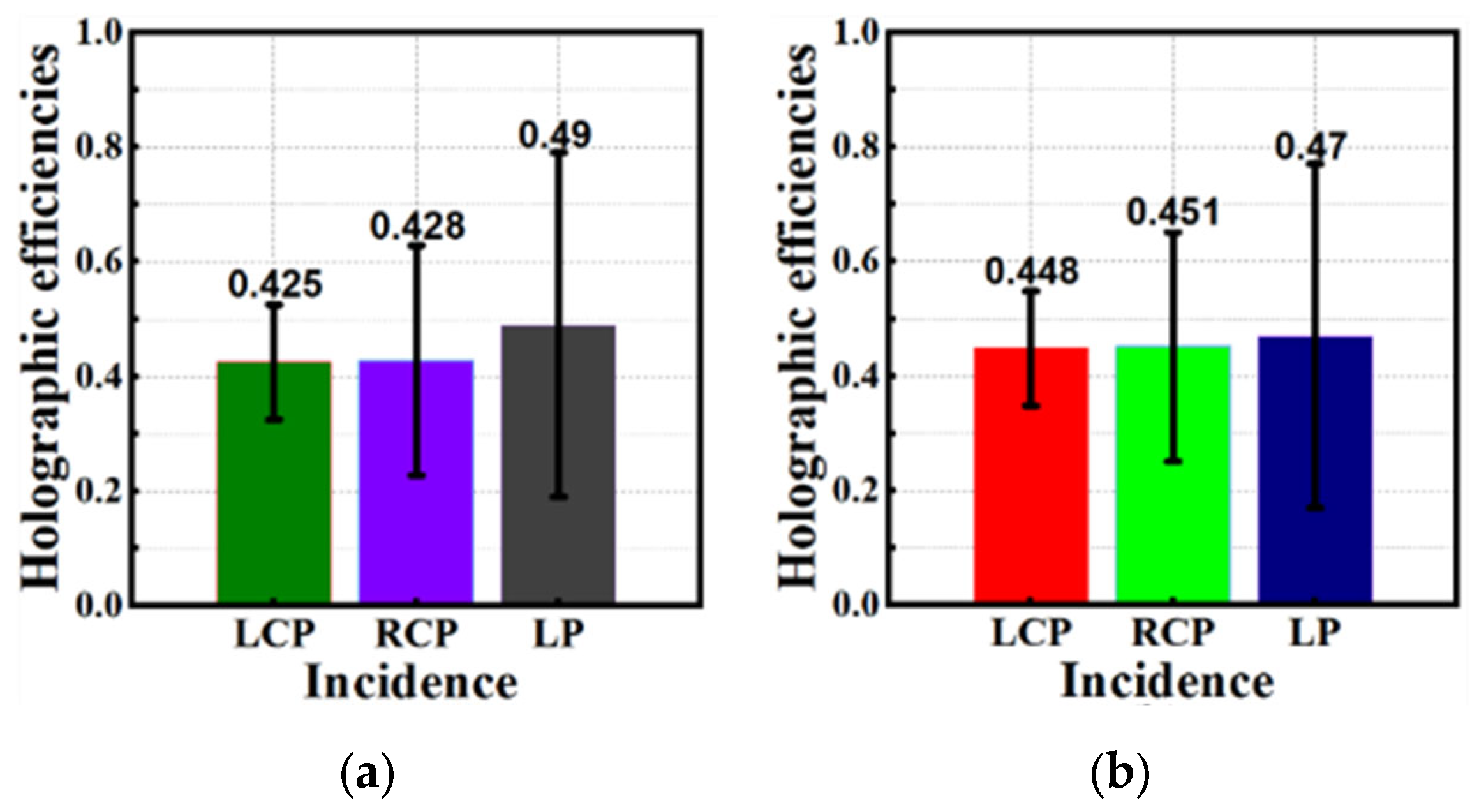
3.3. Holographic Efficiencies

To evaluate the imaging quality of the designed metasurface, we calculated the holographic efficiency for both transmission and reflection modes, as shown in Figure 8. The calculation formula for holographic efficiency is provided in reference [17,25].
η = 0 2 π 0 π E r ( θ , φ ) 2 sin θ d θ d φ 0 2 π 0 π E m ( θ , φ ) 2 sin θ d θ d φ
where η represents the holographic efficiency, Er (θ, φ) and Em (θ, φ) are the far-field scattering patterns from the metasurface and the corresponding metal mirror with the same size, respectively. Figure 10a,b show the holographic efficiencies under LCP, RCP, and LP excitation for the reflection and transmission modes, respectively. The holographic efficiencies for the reflection mode at 1.25 THz under LCP, RCP, and LP incidences are 42.5%, 42.8%, and 49%, respectively. The holographic efficiency for the transmission mode at 1.465 THz are 44.8%, 45.1%, and 47% for the LCP, RCP, and LP incidences, respectively.

4. Discussion

All of the research is based on the metasurface receiving excitation perpendicular to the normal direction. When the metasurface is excited by an oblique incident electromagnetic wave with the same power, the oblique incident beam can be decomposed into electromagnetic wave excitations perpendicular to the normal direction of the metasurface and parallel to the normal direction of the metasurface. Therefore, the electromagnetic power received by the metasurface in the normal direction will decrease, and the imaging efficiency of the metasurface will also decrease accordingly. On the other hand, the electromagnetic wave parallel to the metasurface can be considered as a surface wave, which may couple with the outgoing wave and have a negative impact on the imaging quality of the metasurface.
A comparison of operation frequency, holographic imaging channel number, operation mode number, operation bandwidth, and holographic efficiency has been made between the proposed design and published holographic metasurfaces, as in Table 2. References [9,10,11,17] work only in reflection or transmission mode. Ours works in both reflection and transmission modes, and is reconfigurable for reflection or transmission mode by switching among the RCP, LCP, and LP incidences. In addition, ours has more holographic imaging channel numbers and higher holographic efficiency.
In addition, we also discuss the fabrication of the proposed metasurface. While our design theory has been validated from a simulation perspective, we still face two key challenges. The first challenge pertains to the fabrication of the metasurface. Figure 11 illustrates potential fabrication methods. Firstly, the F4B material layer can be obtained through self-assembly to form the required dielectric substrate. Secondly, there are two methods to obtain the top layer of indium telluride. One approach involves chemical vapor deposition (CVD), whereby indium telluride thin films are deposited on the F4B substrate, with control over temperature, humidity, and deposition rate to achieve the desired material thickness and quality. Another method entails utilizing physical vapor deposition (PVD), employing techniques such as sputtering or evaporation to deposit indium telluride material on the substrate, with the deposition parameters controlled to achieve the desired dielectric properties. Finally, the bottom graphene layer can be prepared through mechanical exfoliation, as described in reference [26,27], for transferring graphene onto the substrate. Alternatively, graphene can be grown directly on the F4B material bottom using CVD, with the precise management of the reaction conditions to achieve the required graphene thickness.
The second challenge pertains to the method of controlling graphene’s chemical potential. As documented in reference [18,20,21,28,29,30,31,32,33,34], the application of an electric field between the graphene layer and the upper dielectric material can effectively manipulate the carrier concentration of graphene, subsequently allowing for the adjustment of the Fermi level. Moreover, techniques such as chemical doping, direct laser writing, the imposition of mechanical strain, and the utilization of piezoelectric effects can be employed to modulate the lattice structure of graphene. This, in turn, alters its electronic properties and facilitates the subsequent adjustment of the Fermi level positioning.

5. Conclusions

This paper develops a multifunctional and reconfigurable reflection-transmission dual-mode THz dielectric holographic metasurface formed by propagation—geometry composite units. The dual-mode is achieved by controlling the Fermi energy level of graphene integrated into the metasurface unit, and the proposed metasurface works in reflection and transmission modes when Ef = 0.9 eV, 0.1 eV, respectively. The reconfigurability is realized by switching incidence polarization. The metasurface is designed based on the transmission mode, and the physical model switching to the reflection mode is established. For the first time, a dynamic modulation reflection–transmission holographic imaging metasurface based on graphene is developed. As an example, a multifunctional and reconfigurable metasurface was developed: (1) reconfigurable cross-polarized three-channel holographic imaging in transmission mode from 1.32 THz to 1.6 THz: (‘Crystals 14 00713 i053’, RCP, θ = −14°, φ = 0°), (‘Crystals 14 00713 i054’, LCP, θ = 17.5°, φ = 0°), and (‘Crystals 14 00713 i055’, RCP, θ = −14°, φ = 0° and ‘Crystals 14 00713 i056’, LCP, θ = 17.5°, φ = 0°) by switching LCP, RCP, and LP incidences, respectively; (2) reconfigurable co-polarized three-channel holographic imaging in reflection mode from 1.15 THz to 1.35 THz: (‘Crystals 14 00713 i057’, RCP, θ = −16°, φ = 0°), (‘Crystals 14 00713 i058’, LCP, θ = 20°, φ = 0°), and (‘Crystals 14 00713 i059’, RCP, θ = −16°, φ = 0°, and ‘Crystals 14 00713 i060’, LCP, θ = 20°, φ = 0°) by switching the RCP, LCP, and LP incidences, respectively. Compared to published holographic imaging, ours has more channel numbers (six holographic imaging channels) and higher holographic efficiency (42.5% to 49%). These characteristics make the proposed metasurface potentially applicable in information encryption transmission, multi-channel imaging, and other related fields.

Author Contributions

Conceptualization, H.-F.H. and J.-Y.W.; methodology, J.-Y.W.; software, J.-Y.W.; validation, H.-F.H. and J.-Y.W.; formal analysis, J.-Y.W.; investigation, J.-Y.W.; resources, J.-Y.W.; data curation, J.-Y.W.; writing—original draft preparation, J.-Y.W.; writing—review and editing, H.-F.H.; visualization, J.-Y.W.; supervision, H.-F.H. and J.-Y.W. All authors have read and agreed to the published version of the manuscript.

Funding

This research was funded by the Guangdong Major Project of Basic and Applied Basic Research (No. 2023B0303000008), the National Key Research and Development Program of China (No. 2020YFB1807300) and the State Key Laboratory of Radio Frequency Heterogeneous Integration (Shenzhen University), No. 202306.

Data Availability Statement

The original contributions presented in this study are included in the article; further inquiries can be directed to the corresponding authors.

Acknowledgments

The valuable comments of the reviewers and associate editor are gratefully appreciated.

Conflicts of Interest

The authors declare no conflicts of interest.

References

  1. Tian, Y.; Wei, Q.; Cheng, Y.; Liu, X. Acoustic holography based on composite metasurface with decoupled modulation of phase and amplitude. Appl. Phys. Lett. 2017, 110, 19190. [Google Scholar] [CrossRef]
  2. Xie, Y.; Shen, C.; Wang, W.; Li, J.; Suo, D.; Popa, B.-I.; Jing, Y.; Cummer, S.A. Acoustic holographic rendering with two-dimensional metamaterial-based passive phased array. Sci. Rep. 2016, 6, 35437. [Google Scholar] [CrossRef]
  3. Chen, W.; Javidi, B.; Chen, X. Advances in optical security systems. Adv. Opt. Photonics 2014, 6, 120–155. [Google Scholar] [CrossRef]
  4. Jiang, Q.; Jin, G.; Cao, L. When metasurface meets hologram: Principle and advances. Adv. Opt. Photonics 2019, 11, 518–576. [Google Scholar] [CrossRef]
  5. Huang, L.; Chen, X.; Mühlenbernd, H.; Zhang, H.; Chen, S.; Bai, B.; Tan, Q.; Jin, G.; Cheah, K.-W.; Qiu, C.-W.; et al. Three-dimensional optical holography using a plasmonic metasurface. Nat. Commun. 2013, 4, 2808. [Google Scholar] [CrossRef]
  6. Li, Z.; Dai, Q.; Mehmood, M.Q.; Hu, G.; Yanchuk, B.L.; Tao, J.; Hao, C.; Kim, I.; Jeong, H.; Zheng, G.; et al. Full-space cloud of random points with a scrambling metasurface. Light Sci. Appl. 2018, 7, 63. [Google Scholar] [CrossRef] [PubMed]
  7. Deng, L.; Deng, J.; Guan, Z.; Tao, J.; Chen, Y.; Yang, Y.; Zhang, D.; Tang, J.; Li, Z.; Li, Z.; et al. Malus-metasurface-assisted polarization multiplexing. Light Sci. Appl. 2020, 9, 101. [Google Scholar] [CrossRef] [PubMed]
  8. Li, Z.; Chen, C.; Guan, Z.; Tao, J.; Chang, S.; Dai, Q.; Xiao, Y.; Cui, Y.; Wang, Y.; Yu, S.; et al. Three-Channel Metasurfaces for Simultaneous Meta-Holography and Meta-Nanoprinting: A Single-Cell Design Approach. Laser Photonics Rev. 2020, 14, 200003. [Google Scholar] [CrossRef]
  9. Wang, H.; Zhang, B.; Han, C.; Ding, J. Polarization-multiplexed wavefront-engineering by all-dielectric metasurface with asymmetric polarization-decoupled meta-atoms. Opt. Express 2021, 29, 32377–32387. [Google Scholar] [CrossRef] [PubMed]
  10. Zhang, Q.; Wang, J.; Xie, R.; Gu, Z.; Zhang, Z.; Wang, X.; Zhang, H.; Chen, C.; Chen, W.; Ding, J.; et al. Four-channel joint- polarization-frequency-multiplexing encryption meta-hologram based on dual-band polarization multiplexing meta-atoms. Opt. Express 2023, 31, 17569–17579. [Google Scholar] [CrossRef] [PubMed]
  11. Zhu, L.; Wei, J.; Dong, L.; Shang, G.; Guan, C.; Burokur, S.N.; Ding, X. Four-channel meta-hologram enabled by a frequency-multiplexed mono-layered geometric phase metasurface. Opt. Express 2024, 32, 4553–4563. [Google Scholar] [CrossRef] [PubMed]
  12. Zhu, L.; Zhou, W.; Dong, L.; Guan, C.; Shang, G.; Ding, X.; Burokur, S.N.; Wu, Q. Full Space Control of Meta-Holograms Utilizing a Bilayered Patterned Coding Metasurface. IEEE Antennas Wirel. Propag. Lett. 2022, 21, 322–326. [Google Scholar] [CrossRef]
  13. Wang, K.; Liao, D.; Wang, H. Reconfigurable origami hologram based on deep neural networks. Opt. Lett. 2024, 49, 2041–2044. [Google Scholar] [CrossRef] [PubMed]
  14. Chen, S.C.; Du, L.H.; Meng, K.; Li, J.; Zhai, Z.H.; Shi, Q.W.; Li, Z.R.; Zhu, L.G. Terahertz wave near-field compressive imaging with a spatial resolution of over λ/100. Opt. Lett. 2019, 44, 21–24. [Google Scholar] [CrossRef] [PubMed]
  15. Liu, H.C.; Yang, B.; Guo, Q.; Shi, J.; Guan, C.; Zheng, G.; Mühlenbernd, H.; Li, G.; Zentgraf, T.; Zhang, S. Single-pixel computational ghost imaging with helicity-dependent metasurface hologram. Sci. Adv. 2017, 3, e1701477. [Google Scholar] [CrossRef] [PubMed]
  16. Dai, Y.; Chen, C.; Gao, P.; Lu, X.; Zhao, J.; Wan, Y.; Wang, X.; Zhao, S.; Liu, H. 3-bit reconfigurable THz metasurface based on structured light illumination for vortex beams and holographic imaging. Opt. Laser Technol. 2024, 169, 109951. [Google Scholar] [CrossRef]
  17. Du, Z.; He, C.; Xin, J.; Song, Z. Terahertz dynamic multichannel holograms generated by spin-multiplexing reflective metasurface. Opt. Express 2023, 32, 248–259. [Google Scholar] [CrossRef]
  18. Ren, B.; Tang, S.; Feng, Y.; Cui, Y.; Liu, J.; Song, J.; Jiang, Y. Dynamic and complete terahertz wavefront manipulation via an anisotropic coding metasurface. Appl. Opt. 2022, 61, 7558–7564. [Google Scholar] [CrossRef] [PubMed]
  19. Cao, G.; Lin, H.; Jia, B.; Yuan, X.; Somekh, M.; Wei, S. Design of a dynamic multi-topological charge graphene orbital angular momentum metalens. Opt. Express 2023, 31, 2102–2111. [Google Scholar] [CrossRef] [PubMed]
  20. Yao, G.; Ling, F.; Yue, J.; Luo, C.; Ji, J.; Yao, J. Dual-band tunable perfect metamaterial absorber in the THz range. Opt. Express 2016, 24, 1518–1527. [Google Scholar] [CrossRef] [PubMed]
  21. Cheng, Y.; Zhu, X.; Li, J.; Chen, F.; Luo, H.; Wu, L. Terahertz broadband tunable reflective cross-polarization convertor based on complementary cross-shaped graphene metasurface. Phys. E Low-Dimens. Syst. Nanostruct. 2021, 134, 114893. [Google Scholar] [CrossRef]
  22. Ding, G.; Chen, K.; Luo, X.; Zhao, J.; Jiang, T.; Feng, Y. Dual-Helicity Decoupled Coding Metasurface for Independent Spin-to-Orbital Angular Momentum Conversion. Phys. Rev. Appl. 2019, 11, 044043. [Google Scholar] [CrossRef]
  23. Gou, Y.; Ma, H.F.; Wu, L.W.; Wang, Z.X.; Xu, P.; Cui, T.J. Broadband Spin-Selective Wavefront Manipulations Based on Pancharatnam–Berry Coding Metasurfaces. ACS Omega 2021, 6, 30019–30026. [Google Scholar] [CrossRef]
  24. Toms, N.; Chapman, J.; Ferrier, R. The application of the gerchberg-saxton algorithm to lorentz microscopy. In Proceedings of the Electron Microscopy 1972: Proceedings of the Fifth European Congress on Electron Microscopy, Manchester, UK, 5–12 September 1972. [Google Scholar]
  25. Xu, J.; Liu, W.; Song, Z. Graphene-based terahertz metamirror with wavefront reconfiguration. Opt. Express 2021, 29, 39574–39585. [Google Scholar] [CrossRef] [PubMed]
  26. Wu, G.; Wang, W.; Zhang, R.; Yan, F.; Liang, L.; Yan, X.; Yao, H.; Wang, Z.; Li, Z.; Xu, L. Metamaterial graphene sensors for the detection of two food additives. Opt. Express 2023, 31, 32162–32171. [Google Scholar] [CrossRef] [PubMed]
  27. Qi, Y.; Zhou, Z.; Shi, Q.; Wen, Y.; Wang, L.; Zhao, S.; Zhang, S.; Wang, X. Dual-function tunable metasurface for polarization-insensitive electromagnetic induction transparency and dual-band absorption. Nanotechnology 2023, 35, 015204. [Google Scholar] [CrossRef] [PubMed]
  28. Zhu, X.; Cheng, Y.; Fan, J.; Chen, F.; Luo, H.; Wu, L. Switchable efficiency terahertz anomalous refraction and focusing based on graphene metasurface. Diam. Relat. Mater. 2022, 121, 108743. [Google Scholar] [CrossRef]
  29. Barzegar-Parizi, S.; Ebrahimi, A.; Ghorbani, K. Two bits dual-band switchable terahertz absorber enabled by composite graphene and vanadium dioxide metamaterials. Sci. Rep. 2024, 14, 5818. [Google Scholar] [CrossRef] [PubMed]
  30. Wang, P.; Han, W.; Tao, H.; Zhang, C.; Xu, Y.; Wang, Q. Multifunctional Graphene Metasurface for Highly Flexible Control of Microwave Absorption. ACS Appl. Mater. Interfaces 2024, 16, 2649–2658. [Google Scholar] [CrossRef] [PubMed]
  31. Fu, C.; Zhang, L.; Zhang, Y.; Li, N.; Gu, S.; Ju, J.; Pan, R.; Liu, X.; Han, L. Bifunctional flexible metasurface based on graphene and vanadium dioxide for polarization conversion and absorption. Diam. Relat. Mater. 2024, 142, 110862. [Google Scholar] [CrossRef]
  32. Shi, H.; Tian, J.; Chen, N.; Zhu, W. Wideband high-efficiency scattering reduction in a graphene based optically transparent and flexible metasurface. Carbon 2024, 225, 119150. [Google Scholar] [CrossRef]
  33. Sabaruddin, N.R.; Tan, Y.M.; Chen, S.H.; Chou Chao, C.T.; Lim, C.M.; Thotagamuge, R.; Kooh, M.R.; Chou Chau, Y.F. Designing a broadband terahertz metamaterial absorber through bi-Layer hybridization of metal and graphene. Plasmonics 2024, 1–14. [Google Scholar] [CrossRef]
  34. Zheng, B.; Zhang, J.; Shan, Y.; Li, N.; Zhang, Y. Wideband RCS Reduction Metasurface Based on Printing Resistive Graphene Ink. IEEE Antennas Wirel. Propag. Lett. 2024, 23, 2041–2045. [Google Scholar] [CrossRef]
Figure 1. Schematic diagram for the dual-mode reconfigurable multifunctional metasurface. (a) Reconfigurable reflection mode. (b) Reconfigurable transmission mode. (c) Two-dimensional graphene-switching sketch map: metal when Ef = 0.9 eV, insulator when Ef = 0.1 eV.
Crystals 14 00713 g001
Figure 2. Basic flowchart of the GS algorithm.
Crystals 14 00713 g002
Figure 3. The transmission–reflection reconfigurable metasurface. The gold and silver arrows represent LCP and RCP excitation sources. The yellow and blue arrows represent the results of two different imaging in reflection mode. Red and pink represent two different imaging results in transmission mode.
Crystals 14 00713 g003
Figure 4. The proposed unit cell: (a) 3D stereogram, (b) top view, (c) side view.
Crystals 14 00713 g004
Figure 5. (a) Simulated S11 and phase shift ϕx(y) as functions of lx(y) at 1.31, 1.325, and 1.336 THz. (b) Simulated S11 and phase shift ϕy(x) as functions of lx(y) at 1.31, 1.325, and 1.336 THz. (c) Simulated S21 and phase shift ϕx(y) as functions of lx(y) at 1.455, 1.465, and 1.473 THz. (d) Simulated S21 and phase shift ϕy(x) as functions of lx(y) at 1.455, 1.465, and 1.473 THz.
Crystals 14 00713 g005
Figure 6. Simulated geometric phase versus β curves when lx = 15 μm.
Crystals 14 00713 g006
Figure 7. Phase distribution for the designed metasurface: (a) propagation phase ϕx; (b) propagation phase ϕy; (c) geometric phase 2β.
Crystals 14 00713 g007
Figure 8. Simulated 3D and 2D far-field holographic imaging under RCP, LCP, and LP incidences: for reflection mode (a) and for transmission mode (b).
Crystals 14 00713 g008
Figure 9. Simulated 3D and 2D far-field holographic imaging under RCP and LCP incidences: (a) co-polarization in reflection mode at 1.15 THz, 1.25 THz, and 1.35 THz; (b) cross-polarization in transmission mode at 1.32 THz, 1.465 THz, and 1.6 THz.
Crystals 14 00713 g009
Figure 10. Holographic efficiencies under LCP, RCP, and LP incidences: (a) for reflection mode at 1.25 THz, (b) for transmission mode at 1.465 THz.
Crystals 14 00713 g010
Figure 11. Fabrication chart of the proposed metasurface. Step I to II: self-assembly. Step II to III: CVD or PVD. Step III to IV: CVD or mechanical exfoliation.
Crystals 14 00713 g011
Table 1. Six holographic imaging channels of the proposed metasurface.
IncidenceFermi EnergyFrequencyChannelHologram (Polarization, Pattern, Reflection Angle)
LCP0.1 eVf1T1 1RCP, ‘Crystals 14 00713 i021’, (θ1, 0°)
0.9 eVf2R1LCP, ‘Crystals 14 00713 i022’, (θ3, 0°)
RCP0.1 eVf1T2LCP, ‘Crystals 14 00713 i023’, (θ2, 0°)
0.9 eVf2R2RCP, ‘Crystals 14 00713 i024’, (θ4, 0°)
LP0.1 eVf1T3RCP, ‘Crystals 14 00713 i025’, (θ1, 0°), and LCP, ‘Crystals 14 00713 i026’, (θ2, 0°)
0.9 eVf2R3RCP, ‘Crystals 14 00713 i027’, (θ4, 0°), and LCP, ‘Crystals 14 00713 i028’, (θ3,0°),
1 (T~ = transmission channel ~, Rx = reflection channel ~).
Table 2. Comparison of the proposed metasurface and published holographic metasurfaces.
ReferenceFrequencyNumber of
Channels
TS or RSRelative BandwidthHolographic Efficiency
[9]375 THz2TS0NA 1
[10]7.5, 13 GHz4RS0NA
[11]7.2, 9.1, 10.9, 15.2 GHz4TS0NA
[17]1.1–1.6 THz4RS37%44.2%, 45.9%
This work1.15–1.35,
1.32–1.6 THz
6TS, RS16%(TS),
19% (RS)
42.5%, 42.8%, 49% (TS),
44.8%, 45.1%, 47% (RS)
1 (NA = not available, TS = transmission state, RS = reflection state).
Disclaimer/Publisher’s Note: The statements, opinions and data contained in all publications are solely those of the individual author(s) and contributor(s) and not of MDPI and/or the editor(s). MDPI and/or the editor(s) disclaim responsibility for any injury to people or property resulting from any ideas, methods, instructions or products referred to in the content.

