Abstract
The tensile properties of reduced activation ferritic/martensitic (RAFM) steels are significantly influenced by neutron irradiation. Here, a mechanism-based model taking account of the typical ductile damage process of void nucleation, growth, and coalescence was used to study the temperature and irradiation effects. The elastic–plastic response of RAFM steels irradiated up to 20 dpa was investigated by applying the GTN model coupled with different work hardening models. Through a numerical study of tensile curves, the GTN parameters were identified reasonably and satisfying simulation results were obtained. A combination of Swift law and Voce law was used to define the flow behavior of irradiated RAFM steels. The deformation localization could be adjusted effectively via setting the nucleation parameter εn close to the strain where necking occurs. Because εn changed with uniform elongation, εn decreased with the testing temperature and rose with an irradiation temperature above 300 °C. The nucleation parameter fn increased with the testing temperature for RAFM steels before irradiation. For irradiated RAFM steels, fn barely changed when the irradiation temperature was below 300 °C and then it rose at a higher irradiation temperature. Meanwhile, the ultimate strength of the simulated and experimental curves showed good agreement, indicating that this method can be applied to engineering design.
1. Introduction
Reduced activation ferritic/martensitic (RAFM) steels are recognized as the most promising structural material given their notable merits: excellent thermal conductivity, lower thermal expansion and ductile–brittle temperature transformation (DBTT), and resistance to irradiation damage. Accordingly, they have been applied in fusion power reactors [1,2,3]. However, the harsh operating environment of a fusion reactor may induce lattice defects and the degradation of RAFMs’ ductility [4,5]. To overcome these effects, it is important to study the transition of material strength and ductility in an irradiation environment close to operating conditions.
Over the past few decades, attempts have been made to investigate the ductile damage to RAFMs, among which the irradiation effects with a spallation neutron source have caused widespread concern. Dai et al. [6] studied the tensile properties of F82H in a temperature range of 90–370 °C and different doses of between 3 and 12 dpa. They found that the irradiation hardening effect increased with the dose and that the ductility decreased obviously at the same time, while a high temperature could cause the recovery of ductility. Subsequently, the tensile properties of EM10 [7], EUROFER97 [8], and CLAM [9] were researched, with all studies recording the degradation of material properties, induced by a higher temperature and irradiation. Meanwhile, with the substantial development of characterization techniques, mounting microscopic evidence reveals that temperature and irradiation influence the damage mechanism associated with microstructural evolution [10,11,12]. Meanwhile, the finite element (FE) approach has been used in all kinds of steels to study the damage progress during deformation [13,14,15]. Because of the limits of irradiation specimens and the complexity of insitu testing, the FE approach should be adopted to analyze the damage mechanism quantitatively and predict the ductile-to-brittle transition (DBT) region, with such research both feasible and imperative.
It is commonly recognized that the main ductile damage mechanism is driven by void evolution for metallic alloys [16,17]. The Gurson–Tvergaard–Needleman (GTN) model is a mechanism-based model for describing the ductile damage to metals, which has been employed to study the void nucleation and coalescence induced by inclusions at high temperatures [18]. Meanwhile, irradiation introduces lattice defects like vacancies, self-interstitial atoms, dislocation loops, and so on. Although these defects cannot act as potential nuclei for ductile damage due to their nanoscale size [19], the formation of dislocation channels causes increased yield stress and premature plastic instability [20,21]. In turn, the higher yield stress of irradiated materials causes carbide particles to break, giving rise to the formation of cleavage microcracks. This process is considered as in competition with ductile fractures mediated by microvoids. Recently, Chakraborty et al. [22] studied the tensile properties of EUROFER97 irradiated at low dose of up to 1.5 dpa, with the GTN model firstly and then the DBT of EUROFER97, under the same irradiation condition as were simulated efficaciously by Chen et al. [23], who combined a probabilistic cleavage fracture model with a GTN model. They successfully reproduced the change in ductile behavior of EUROFER97 under a small dose range. However, more investigations on the ductile damage to RAFM steels under a wide dose range are needed.
The aim of this work was to identify the parameters of GTN models for RAFM steels based on the available tensile tests after irradiation with a spallation neutron source. Moreover, the transition of material strength and ductility, mediated by temperature and the irradiation effect, were investigated through a series of simulation tensile tests at temperatures from RT to 350 °C and irradiation up to 20 dpa. Finally, in this article, the ductile damage behavior and the influence of temperature and irradiation on microscopic parameters in the GTN model are discussed.
2. Numerical Simulation Methods
2.1. Ductile Damage Model
The concept of the GTN model was derived from the physical background of the ductile damage mechanism, where the fracture of metal materials depends on void nucleation, growth, and coalescence. Thus, the porous plasticity was constructed by Gurson in the classic Von Mises yield condition by considering hydrostatic stress and porosity, represented as follows [24]:
where is the Von Mises equivalent stress, σy is the yield stress of the matrix material, and σm is the mean of three principal stresses (hydrostatic stress). The variable , which functions as a damage parameter in the constitutive equation, is defined as the ratio of the volume of voids to the total volume of the material. Significantly, if there is no or relatively low ductile damage, namely tends toward zero, then the solution to Equation (1) will be close to the Von Mises yield condition.
In view of the fact that localized internal necking of the matrix results in interaction between the neighboring voids, the parameters q1, q2, and q3 were incorporated into the model by Tvergaard. Furthermore, the effective void volume was introduced to represent the rapid loss of stress carrying capacity that accompanies voids’ coalescence:
where represents the critical void volume where void coalescence occurs; is the void fraction at fracture; is the value of at fracture; and . In addition, the initial value of the void volume, , is needed.
Two damage mechanisms, which take account of void growth and nucleation, are combined in the model. Hence, the evolution equation of void volume () is decomposed into the contributions from the growth rate of existing voids and the nucleation rate of new voids, expressed as follows:
The growth rate of voids is related to the volume dilatation of the matrix, which is proportional to the plastic hydrostatic strain, :
The nucleation of voids is propelled by plastic strain, which is given by the normal distribution relationship:
where and are the mean value and standard deviation, respectively, of the normal distribution of nucleation strain; is the volume fraction of the potentially nucleated voids; and is the rate of equivalent plastic strain.
2.2. Finite Element Model of Tensile Test
Uniaxial tensile experiments were performed with miniature flat tensile specimens, which have been widely used for irradiation tests. A diagram of these specimens is shown in Figure 1. Based on the tensile specimens, an axisymmetric FEM model was established in ABAQUS/Explicit, as shown in Figure 2. To simplify the contact effect during the tensile process, a displacement constraint was exerted along the tensile direction and one end of the specimen was fixed. It has to be mentioned that ductile fracture is sensitive to the strain rate in experiments and that tensile tests should be conducted in a quasi-static state. Normally, the strain rate in experimental tensile tests is 10−3 s−1, while the GTN model used in FE simulation is rate independent. Therefore, a high strain rate (0.4 s−1) was selected in our simulation work to improve the computing efficiency. Meanwhile, the quasi-static state was guaranteed by keeping the kinematic energy of the simulation model lower than 5% of the internal energy during the FEM analysis. An 8-node linear hexahedral solid element with reduced integral (C3D8R) was employed to improve the computing efficiency, and the mesh size in the gauge was refined to 0.05 mm for the sake of mesh sensitivity. The GTN damage model was implemented by applying porous plasticity in ABAQUS, and the flow stress behavior was defined via a user-subroutine VUHARD.
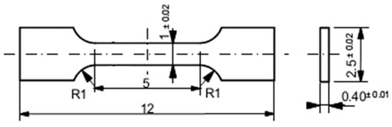
Figure 1.
The diagram of miniature flat tensile specimens.
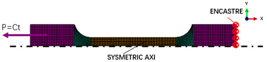
Figure 2.
FEM model of uniaxial tensile specimen.
2.3. Flow Stress Behavior
In this work, the tensile properties of two reduced activation ferritic martensitic steels were studied. The F82H steel, IEA Heat 974, has the chemical composition of 7.87Cr, 1.98W, 0.03Ta, 0.02Ni, 0.003Mo, 0.1Mn, 0.04Ti, 0.19V, 0.002Nb, 0.01Cu, 0.09C, 0.07Si, 0.003P, and 0.007N in wt% Fe balance. The F82h steel was normalized at 1040 °C for 38 min and tempered at 750 °C for 1 h. The CLAM steel, HEAT 0408B, has the main chemical composition of 8.91Cr, 1.44W, 0.2V, 0.15Ta, 0.49Mn, 0.11Si, and 0.12C, and it was normalized at 980 °C for 30 min followed by air-cooling, then tempered at 760 °C for 1.5 h and air-cooled. The Young’s modulus (E) and Poisson’s ratio (v) values of F82H and CLAM were determined by referring to design data for RAFM [25], and the hardening parameters were obtained by fitting the true stress–strain curves of corresponding materials [6,9] till reaching the ultimate tensile stress (UTS) with the least-squares method. The Swift working–hardening law was adopted to describe the strain-hardening behavior of the materials, which is suitable to simulate the plastic deformation of steels in virtue of its unsaturated hardening [26]. The form is as follows:
where A is the yield stress amplitude, n is the hardening exponent, and is the initial yield strain.
Nevertheless, lattice damage will change the hardening behavior of materials in irradiation scenarios, giving rise to premature necking or cleavage fracture with slight plastic deformation. Accordingly, a saturate hardening law configured in the form of the Voce equation was incorporated into the Swift law to provide a strain-softening effect. The form of the Swift–Voce hardening model is as follows:
where α is the weighting coefficient; K0 is the initial yield stress in the Voce law; and Q and B are the amplitude factors. All hardening parameters are listed in Table 1 and Table 2.

Table 1.
Mechanical properties and hardening parameters of RAFM steels at different testing temperatures.
Table 2.
Mechanical properties and hardening parameters of irradiated RAFM steels at various doses and room temperature.
3. Results
The Swift law was employed in fitting the flow behavior of unirradiated materials, and we found that the hardening exponent n showed a significant decline at RT when compared with the elevated temperature. It also should be noted that the variation in n as a function of temperature was not always steady, with a minimal value of about 0.061 near 300 °C shown in Table 1. For irradiated materials, the Swift–Voce hardening law was selected to ensure a good agreement between the simulation results and the experimental curves with less uniform elongation. The results in Table 2 show that the weighting coefficient α tended toward nonsaturated hardening at higher doses.
A parameter study was conducted to calibrate the GTN model by comparing the feature points of the experiment and the simulation tensile curve. The simulation curve at RT is shown in Figure 3. Firstly, we found that the initial void volume f0 depended on the volume of inclusions, and since, in RAFM steels, the size of inclusions is small, this led to a low magnitude of f0. f0 = 0.0003 was considered, from Refs. [22,27], since the cited studies involved similar components of ferritic/martensitic steels. Furthermore, f0 was fixed in our study as we considered there to be a limited influence of the very low initial void volume. The parameters q1 = 1.5, q2 = 1, and q3 = q12 were selected as recommended in Ref. [28].
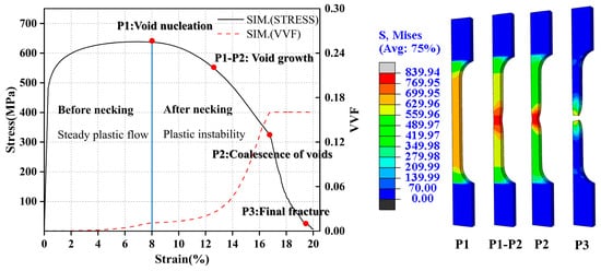
Figure 3.
Simulation results of F82H steels at RT (VVF represents void volume fraction and P1–P3 are different stages of void evolution).
The three nucleation parameters—fn, εn, and sn—were adjusted synchronously. From Equation (2), it is reasonable to infer that the nucleation of voids that takes place with plastic deformation will have the reverse impact compared to the hardening law. When the softening effect induced by f outweights hardening, this will result in the beginning of necking. Consequently, εn should be set near the strain of the ultimate tensile strength, as per the P1 point in Figure 3, given the hypothesis that voids’ nucleation is most likely to take place near necking, and sn is set proportional to εn for a sufficient frequency of nucleation events triggering plastic instability. The initial guess of fn = 0.02 was taken from Ref. [29], and this was calibrated to increase or decrease the influence of softening in a range from 0.001 to 0.1. It is noteworthy that, although the nucleation void volume only accounts for a small part of the total f, the competition between hardening and softening will be substantially affected by the nucleation period. Thus, the nucleation parameters were studied adequately and are discussed deeply in the next section of the article.
The fracture parameters fc and ff, were determined after the nucleation parameters. There was a rapid drop in yield stress before fracturing, reflected by the sharp increase in f at the P2 point in Figure 3, and thus the turning point of this phenomenon was the critical value of the void volume, namely fc. In this work, fc was set above fn and calibrated according to the fracture strength. After exceeding the critical value, the void volume would develop continuously until reaching the final void volume ff, and the element would be deleted at the P3 point in Figure 3. However, the tensile test was not sensitive to the crack propagation process, and slight differences occurred when we changed ff and when a higher value than fc was set as ff.
A similar parameter calibration study was conducted in F82H and CLAM. To study the temperature and irradiation effects, the tensile curves of these materials were simulated, with RT to 350 °C used and with a dose range from 5.7 to 20 dpa selected for irradiated materials. The main studied GTN parameters were calibrated until we reached a satisfactory agreement with the experimental curves; the results are shown in Table 3 and Table 4.
Table 3.
GTN parameters of F82H at different temperatures and irradiation doses.
Table 4.
GTN parameters of CLAM at different irradiation doses and room temperature.
The tensile curves of F82H at RT to 350 °C before irradiation are shown in Figure 4. As can been seen, all simulation curves fit well with those of the experiments, especially before the necking stage. After the necking stage, a feasible prediction is obtained by the GTN model, with modest differences from the experiment results like the simulation curve of F82H at 350 °C in Figure 4. From the deformation progress of the FE model in Figure 3, it can be inferred that a localization of massive plastic deformation eventuated the complex stress state in the necking area, while the GTN model had a weakness in its inability to take in account the effect of shearing damage [30], which might have caused the discrepancy above. The results of the CLAM tensile curves are shown in Figure 4, obtained under the circumstance that the FE model and relevant settings were kept same as with the previous methods. As can be seen, all simulation curves achieved a good agreement with the experiments. It is interesting that both the hardening model and the GTN model played a crucial role in the simulation works. The uniform deformation before necking was mainly controlled by the hardening model while, after necking, the relation between strain and stress was determined by the coupling mechanism of hardening and ductile damage.
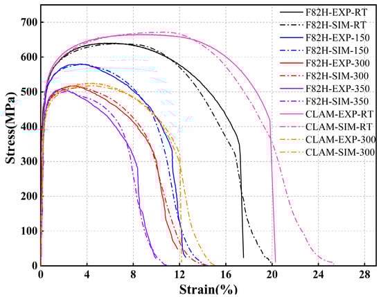
Figure 4.
The simulation and experimental curves of F82H and CLAM at different temperatures.
The results of four irradiated FM steels at RT are displayed in Figure 5. The same parameter study methods were employed to identify the hardening and damage behavior. It is clear from Figure 5 that the damage behavior of irradiated materials was rather different, with a shorter hardening stage and with a drop stage that was less convex or almost linear (F82H at a dose of 5.7 dpa) when compared with the unirradiated material in the tensile curves. Thus, the Swift–Voce law was utilized in these simulations since it has the advantage that the saturated hardening component (Voce) provides less strain hardening when there is damage localization. Although a general agreement was achieved in the simulated results, as shown in Figure 4 and Figure 5, there is an important material strength point that we must highlight: the UTS seemed to deviate from the experimental curves slightly, especially when the testing temperature was above 300 °C and the irradiation dose was above 10 dpa. The deviation may have originated from the lesser plastic deformation in the hardening period, as can be seen commonly in experimental curves, and since there were fewer data points available for fitting a true stress–strain curve from the macro perspective. Meanwhile, the flow behavior may be influenced by an embrittlement mechanism at a high testing temperature and irradiation dose. In general, the slight deviation of the UTS was acceptable, and we propose that the GTN model can be applied to engineering design when the stress state of materials is not too complex.
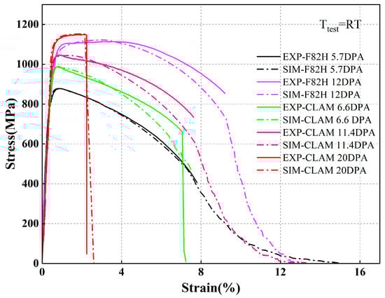
Figure 5.
The simulation and experimental curves of irradiated F82H and CLAM at room temperature.
4. Discussion
It can be summarized from the tensile curves in Figure 4 that the YS, UTS, and total elongation all declined with the increase in temperature. To infer the temperature effect from the GTN parameters, the relationship between nine damage parameters and temperature for F82H is charted in Figure 6. The three nucleation parameters, which are colored red in Figure 6, have a notable response to temperature changes. It is clear that εn and sn decrease with total elongation, which occurs since the parametric study of εn is based on the plastic strain near necking and since sn is proportional to εn. Meanwhile, the transformation of fn is almost the reverse of that of εn, meaning that voids will nucleate with less plastic deformation under a higher temperature. For most ferritic/martensitic steels, suitable generation locations of microvoids are nonmetallic inclusions, second-phase particles, and dislocation pile-ups. When the temperature of a metal increases, the energy of the grain matrix and boundary decreases and the diffusion and migration of defects such as dislocations and vacancies are easier. When the temperature is lower than 40% of the melting point, the strength of the gain boundary is consistently greater than that of the matrix, and dislocation movement will be impeded at interfaces like inclusions, particles, and grain boundaries. To some degree, the nucleation of microvoids will be promoted by the diffusion and migration of defects. Meanwhile, a high temperature will lead to the growth and thermal expansion of MC-type carbides [31]. This inconsistent deformation of carbides and the matrix leads to an accumulation of dislocations and stress concentration at interfaces, leaving the steel prone to void nucleation. As a result, the volume of void nucleation fn increases continuously and the mean nucleation strain εn decreases with the overall temperature. The influence of temperature can also be illustrated by the SEM results of fractography [32], shown in Figure 7, where an increase in the number of void nucleation events leads to an increase in the number of dimples and craters but a decrease in the size and depth of dimples on the fracture surface at a moderate temperature. When the temperature is above 300 °C, more brittle fracture characteristics can be found. To compensate for softening effects, fn continually increases to bring about a larger void volume. However, brittle damage is not included in the GTN model and it is difficult to find reasonable relations between fn and fractography above 300 °C.
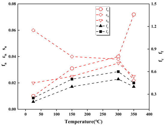
Figure 6.
Changes of GTN parameters of F82H with temperature, where the black lines represent the values of fc and ff, referring to the left y-axis, while the red lines are the values of nucleation parameters fn, εn, and sn, referring to the right y-axis.
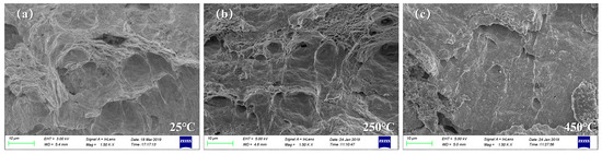
Figure 7.
Fracture surfaces of CLF−1 steel at different temperatures with a magnification of 1500× [32]. (a) Tested at 25 °C; (b) tested at 250 °C; (c) tested at 450 °C.
Figure 5 reveals that the irradiated material exhibited a significant irradiation embrittlement effect and irradiation hardening effect, where the yield stress increased dramatically and elongation decreased obviously. The evolution of microstructures was studied in terms of GTN parameters for the microscopic information they possessed. The GTN parameters of irradiated F82H and CLAM were counted, as shown in Figure 8. Compared to the temperature effect before irradiation, we found a similar scenario where εn changed with uniform elongation. Attention was also paid to the nucleation parameters, and fn showed similar regulation where at a dose smaller than 12 dpa, all the FM steels had relatively small values of fn (close to the unirradiated FM steels at RT), while fn rose at higher doses. In an irradiation environment, defects will be introduced to materials, and the movement of dislocations may sweep out, absorb, or destroy irradiation-produced defects, leading to the formation of dislocation channels in material and to deformation localization [33]. Since the dislocation movement was concentrated on defect-free channels, saturated hardening constituted a large proportion of the flow behavior, which brought about a weaker hardening effect and a potential slight change of fn. However, the defects had a larger size and smaller number at a higher irradiation temperature, introducing a higher yield stress and causing breaks of carbide particles, leading to an increase in fn [19,23]. In addition, dislocation movement will be impeded for defect segregation at irradiation temperatures, which causes an increase in the weight of unsaturated hardening. However, the SEM results for fractography revealed that intergranular and cleavage fractures could be found with doses of above 12 dpa [6,34]. Therefore, similar to the conditions at higher test temperatures, there were limited GTN parameters in response to fractography dominated by brittle damage with doses of above 11 dpa, particularly at irradiation temperatures of above 300 °C, probably due to non-hardening embrittlement.
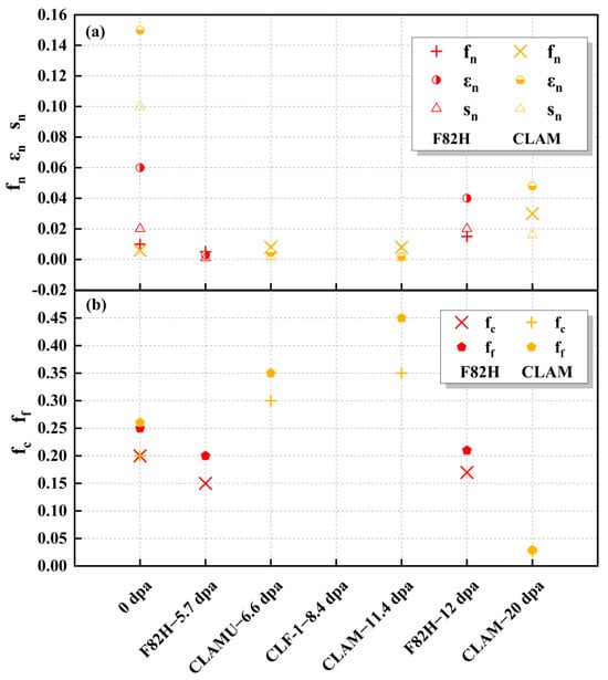
Figure 8.
The GTN parameters of irradiated FM steels (F82H is marked by red, CLAM is marked by orange) at different irradiation doses. (a) The value of nucleation parameters fn, εn, and sn; (b) the value of fracture parameters fc and ff.
In addition, fc and ff also decreased at the highest irradiation dose, as can be seen from Figure 8b, especially when compared with the unirradiated FM steels. The decline in these two fracture parameters indicated that there were fewer nucleation events for microvoids. It also indicated that the coalescence of voids occurs in localized regions at earlier stages and represents a decline in damage tolerance induced by the irradiation embrittlement effect.
5. Conclusions
In the present work, the elasticplastic response of RAFM steels at RT to 350 °C and with irradiation doses from 5.7 to 20 dpa was investigated by utilizing the GTN model and different work hardening models. Multiple parameter iterations were performed to define the GTN model by comparing the tensile curves of the simulations and experiments. To sum up, the main results of this work are as follows:
- Through a numerical study of tensile curves, the GTN parameters were identified reasonably and we obtained satisfying simulation results for RAFM steels. For irradiated materials, the combination of Swift law and Voce law was used to define the flow behavior. Meanwhile, we found that the proportion of saturated hardening (Swift law) rose with the recovery of uniform elongation.
- The deformation localization can be adjusted effectively by setting εn at the strain near necking, leading εn to change with uniform elongation. Therefore, εn decreased with the testing temperature and rose with irradiation at temperatures above 300 °C.
- The nucleation parameter fn increased with the testing temperature before irradiation. In the irradiation tests, there was barely any change in fn at low irradiation temperatures of below 300 °C and then there was a rise in fn at higher irradiation temperatures. Nevertheless, the fractography dominated by brittle fracturing may not be related to fn in the GTN model for ductile damage.
Finally, it must be mentioned that there are still some limitations to the GTN model for studying the non-hardening embrittlement and shear-dominated void coalescence of RAFM steels. To overcome these, shear damage and brittle fracture mechanisms should be incorporated into the constitutive model in further studies.
Author Contributions
Conceptualization, methodology, investigation, data curation, writing—original draft, Y.L.; conceptualization, investigation, writing—review and editing, Y.X.; project administration, supervision, writing—review and editing, L.P.; resources, writing—review and editing, J.S.; writing—review and editing, S.C. and Y.S. All authors have read and agreed to the published version of the manuscript.
Funding
The work was sponsored by the National Natural Science Foundation of China (Nos. 12175231 and 11805131), Anhui Natural Science Foundation of China (No. 2108085J05), and the Collaborative Innovation Program of Hefei Science Center, CAS (No. 2022HSC-CIP009).
Data Availability Statement
The datasets that support the results of this study are available from the corresponding author upon reasonable request.
Conflicts of Interest
The authors declare no conflicts of interest.
References
- Lian, J.; Sharaf, M.; Archie, F.; Münstermann, S. A hybrid approach for modelling of plasticity and failure behaviour of advanced high-strength steel sheets. Int. J. Damage Mech. 2012, 22, 188–218. [Google Scholar] [CrossRef]
- Tanigawa, H.; Gaganidze, E.; Hirose, T.; Ando, M.; Zinkle, S.J.; Lindau, R.; Diegele, E. Development of benchmark reduced activation ferritic/martensitic steels for fusion energy applications. Nucl. Fusion 2017, 57, 092004. [Google Scholar] [CrossRef]
- Liao, H.B.; Wang, X.Y.; Yang, G.P.; Feng, Y.J.; Wang, P.H.; Feng, K.M. Recent progress of R&D activities on reduced activation ferritic/martensitic steel (CLF-1). Fusion Eng. Des. 2019, 147, 111235. [Google Scholar]
- Tavassoli, A.A.F. Present limits and improvements of structural materials for fusion reactors—A review. J. Nucl. Mater. 2002, 302, 73–88. [Google Scholar] [CrossRef]
- Zinkle, S.J. Fusion materials science: Overview of challenges and recent progressa). Phys. Plasmas 2005, 12, 058101. [Google Scholar] [CrossRef]
- Dai, Y.; Long, B.; Tong, Z.F. Tensile properties of ferritic/martensitic steels irradiated in STIP-I. J. Nucl. Mater. 2008, 377, 115–121. [Google Scholar] [CrossRef]
- Henry, J.; Averty, X.; Dai, Y.; Pizzanelli, J.P. Tensile behaviour of 9Cr–1Mo tempered martensitic steels irradiated up to 20dpa in a spallation environment. J. Nucl. Mater. 2008, 377, 80–93. [Google Scholar] [CrossRef]
- Bhattacharya, A.; Chen, X.; Graening, T.; Geringer, J.W.; Reed, J.; Henry, J.; Pilloni, L.; Terentyev, D.; Puype, A.; Byun, T.S.; et al. Irradiation hardening and ductility loss of Eurofer97 steel variants after neutron irradiation to ITER-TBM relevant conditions. Fusion Eng. Des. 2021, 173, 112935. [Google Scholar] [CrossRef]
- Ge, H.E.; Peng, L.; Dai, Y.; Huang, Q.Y.; Ye, M.Y. Tensile properties of CLAM steel irradiated up to 20.1 dpa in STIP-V. J. Nucl. Mater. 2016, 468, 240–245. [Google Scholar] [CrossRef]
- Huang, X.; Yi, J.H.; Ding, J.; Song, K.; Lu, S.Q.; Liu, H.; Wang, L.S. Radiation damage behavior and mechanism in RAFM steel: Orientation effect. Vacuum 2022, 205, 111445. [Google Scholar] [CrossRef]
- Xia, L.D.; Huo, X.J.; Chen, H.; Yang, Z.G.; Zhang, C. Experimental and Theoretical Analysis of Void Evolution During Irradiation in 0.29V-0.09Ta RAFM Steel. Rare Met. Mater. Eng. 2021, 50, 1139–1145. [Google Scholar]
- Chen, J.G.; Liu, C.X.; Liu, Y.C.; Yan, B.Y.; Li, H.J. Effects of tantalum content on the microstructure and mechanical properties of low-carbon RAFM steel. J. Nucl. Mater. 2016, 479, 295–301. [Google Scholar] [CrossRef]
- Simonovski, I.; Holmström, S.; Baraldi, D.; Delville, R. Investigation of cracking in small punch test for semi-brittle materials. Theor. Appl. Fract. Mech. 2020, 108, 102646. [Google Scholar] [CrossRef]
- Chiyatan, T.; Uthaisangsuk, V. Mechanical and fracture behavior of high strength steels under high strain rate deformation: Experiments and modelling. Mater. Sci. Eng. A 2020, 779, 139125. [Google Scholar] [CrossRef]
- Tiwari, A.; Singh, R.N.; Ståhle, P.; Chakravartty, J.K. Master curve in upper region of ductile brittle transition: A modification based on local damage approach. In Proceedings of the 21st European Conference on Fracture, (ECF21), Catania, Italy, 20–24 June 2016; pp. 1553–1560. [Google Scholar]
- Tvergaard, V.; Needleman, A. An analysis of the brittle-ductile transition in dynamic crack growth. Int. J. Fract. 1993, 59, 53–67. [Google Scholar] [CrossRef]
- Hug, E.; Martinez, M.; Chottin, J. Temperature and stress state influence on void evolution in a high-strength dual-phase steel. Mater. Sci. Eng. A 2015, 626, 286–295. [Google Scholar] [CrossRef]
- Wang, C.; Liu, X.G.; Gui, J.T.; Du, Z.L.; Xu, Z.F.; Guo, B.F. Effect of MnS inclusions on plastic deformation and fracture behavior of the steel matrix at high temperature. Vacuum 2020, 174, 109209. [Google Scholar] [CrossRef]
- Tanguy, B.; Bouchet, C.; Bugat, S.; Besson, J. Local approach to fracture based prediction of the ΔT56J and ΔTKIc,100 shifts due to irradiation for an A508 pressure vessel steel. Eng. Fract. Mech. 2006, 73, 191–206. [Google Scholar] [CrossRef]
- Farrell, K.; Byun, T.S. Tensile properties of ferritic/martensitic steels irradiated in HFIR, and comparison with spallation irradiation data. J. Nucl. Mater. 2003, 318, 274–282. [Google Scholar] [CrossRef]
- Tanigawa, H.; Klueh, R.L.; Hashimoto, N.; Sokolov, M.A. Hardening mechanisms of reduced activation ferritic/martensitic steels irradiated at 300 °C. J. Nucl. Mater. 2009, 386–388, 231–235. [Google Scholar] [CrossRef]
- Chakraborty, P.; Biner, S.B. Parametric study of irradiation effects on the ductile damage and flow stress behavior in ferritic-martensitic steels. J. Nucl. Mater. 2015, 465, 89–96. [Google Scholar] [CrossRef]
- Chen, L.R.; Liu, W.B.; Yu, L.; Cheng, Y.Y.; Ren, K.; Sui, H.N.; Yi, X.; Duan, H.L. Probabilistic and constitutive models for ductile-to-brittle transition in steels: A competition between cleavage and ductile fracture. J. Mech. Phys. Solids 2020, 135, 103809. [Google Scholar] [CrossRef]
- Gurson, A.L. Continuum Theory of Ductile Rupture by Void Nucleation and Growth: Part I—Yield Criteria and Flow Rules for Porous Ductile Media. J. Eng. Mater. Technol. 1977, 99, 2–15. [Google Scholar] [CrossRef]
- Tavassoli, A.A.F.; Rensman, J.W.; Schirra, M.; Shiba, K. Materials design data for reduced activation martensitic steel type F82H. Fusion Eng. Des. 2002, 61–62, 617–628. [Google Scholar] [CrossRef]
- Djouabi, M.; Ati, A.; Manach, P.Y. Identification strategy influence of elastoplastic behavior law parameters on Gurson-Tvergaard-Needleman damage parameters: Application to DP980 steel. Int. J. Damage Mech. 2019, 28, 427–454. [Google Scholar] [CrossRef]
- Samal, M.K.; Seidenfuss, M.; Roos, E.; Dutta, B.K.; Kushwaha, H.S. Experimental and numerical investigation of ductile-to-brittle transition in a pressure vessel steel. Mater. Sci. Eng. A 2008, 496, 25–35. [Google Scholar] [CrossRef]
- Tvergaard, V. Influence of void nucleation on ductile shear fracture at a free surface. J. Mech. Phys. Solids 1982, 30, 399–425. [Google Scholar] [CrossRef]
- Soyarslan, C.; Gülçimen, B.; Bargmann, S.; Hähner, P. Modeling of fracture in small punch tests for small- and large-scale yielding conditions at various temperatures. Int. J. Mech. Sci. 2016, 106, 266–285. [Google Scholar] [CrossRef]
- West, O.; Lian, J.H.; Münstermann, S.; Bleck, W. Numerical Determination of the Damage Parameters of a Dual-phase Sheet Steel. ISIJ Int. 2012, 52, 743–752. [Google Scholar] [CrossRef]
- Wang, Y.L.; Song, K.X.; Zhang, Y.M.; Wang, G.X. Microstructure evolution and fracture mechanism of H13 steel during high temperature tensile deformation. Mater. Sci. Eng. A 2019, 746, 127–133. [Google Scholar] [CrossRef]
- Xie, Y.; Peng, L.; Zhang, W.Z.; Liao, H.B.; Qian, G.A.; Wan, Y.X. Temperature effect on fracture toughness of CLF-1 steel with miniature three-point bend specimens. J. Nucl. Mater. 2020, 531, 151992. [Google Scholar] [CrossRef]
- Cui, Y.; Po, G.; Ghoniem, N. Size-Tuned Plastic Flow Localization in Irradiated Materials at the Submicron Scale. Phys. Rev. Lett. 2018, 120, 215501. [Google Scholar] [CrossRef] [PubMed]
- Yakushiji, K.; Lee, H.T.; Oya, M.; Tokitani, M.; Sagara, A.; Hamaji, Y.; Uenishi, K.; Ibano, K.; Ueda, Y. Erosion and morphology changes of F82H steel under simultaneous hydrogen and helium irradiation. Fusion Eng. Des. 2017, 124, 356–359. [Google Scholar] [CrossRef]
Disclaimer/Publisher’s Note: The statements, opinions and data contained in all publications are solely those of the individual author(s) and contributor(s) and not of MDPI and/or the editor(s). MDPI and/or the editor(s) disclaim responsibility for any injury to people or property resulting from any ideas, methods, instructions or products referred to in the content. |
© 2024 by the authors. Licensee MDPI, Basel, Switzerland. This article is an open access article distributed under the terms and conditions of the Creative Commons Attribution (CC BY) license (https://creativecommons.org/licenses/by/4.0/).