Abstract
Environmentally friendly lead-free K1-xNaxNbO3 (KNN) ceramics possess electromechanical properties comparable to lead-based ferroelectric materials but cannot meet the needs of device miniaturization, and the corresponding thin films lack theoretical and experimental studies. To this end, we developed the nonlinear phenomenological theory for ferroelectric materials to study the effects of non-equiaxed misfit strain on the phase structure, electromechanical properties, and electrical response of K0.5Na0.5NbO3 epitaxial films. We constructed in-plane misfit strain () phase diagrams. The results show that K0.5Na0.5NbO3 epitaxial film under non-equiaxed in-plane strain can exhibit abundant phase structures, including orthorhombic , , and phases, tetragonal , , and phases, and monoclinic phases. Moreover, in the vicinity of , , and phase boundaries, K0.5Na0.5NbO3 epitaxial films exhibit excellent dielectric constant , while at and phase boundaries, a significant piezoelectric coefficient is observed. It was also found that high permittivity and piezoelectric coefficients exist near the , , and phase boundaries due to the existence of polymorphic phase boundary (PPB) in the KNN system, which makes it easy to polarize near the phase boundaries, and the polarizability changes suddenly, leading to electromechanical enhancement. In addition, the results show that the K0.5Na0.5NbO3 thin films possess a large electrocaloric response at the phase boundary at the and phase boundaries. The maximum adiabatic temperature change is about 3.62 K when the electric field change is 30 MV/m at room temperature, which is significantly enhanced compared with equiaxed strain. This study provides theoretical guidance for obtaining K1−xNaxNbO3 epitaxial thin films with excellent properties.
1. Introduction
Ferroelectric materials have electromechanical coupling properties due to the existence of spontaneous polarization [1,2] and have been widely used in electronic components such as capacitors, memories, actuators, et al. [3,4]. Traditional refrigeration cannot meet the local refrigeration of small devices. In contrast, solid-state refrigeration technology based on the electrocaloric effect, with the advantages of high-efficiency, environmental friendliness, lightweight, and easy miniaturization, is one of the ideal technologies to replace traditional compressor refrigeration [5,6]. Pb(ZrxTi1−x)O3 (PZT) ceramics are among the most widely studied ferroelectric materials [7,8], and possess excellent performance due to their morphotropic phase boundary (MPB). The phase structure changes suddenly near the MPB, leading to enhanced electromechanical response [9,10,11]. In 2006, Mischenko et al. discovered the giant electrocaloric temperature change of 12 K in PbZr0.95Ti0.05O3 ferroelectric thin films [12]. However, lead-based ceramics are harmful to human health and the environment [13,14]. Therefore, to meet the needs of sustainable human development, the research and development of lead-free piezoelectric materials have become the general trend.
In 2004, Saito et al. first prepared K1−xNaxNbO3 (KNN) textured ceramics with excellent piezoelectric properties ( pC/N) near the O-T phase boundary [15]. They then reported that modified and highly textured KNN-based lead-free piezoelectric ceramics possess high piezoelectric coefficients reaching 500~700 pC/N, equivalent to those in PZT [16,17]. Koruza et al. measured the electrocaloric effect of KNN-0.15ST and obtained the electrocaloric temperature change () of 1.9 K under an electric field of 159 kV/cm and at a temperature of 340 K [18]. KNN-based ceramics have become promising lead-free ferroelectric materials and are the best substitutes for PZT materials, which have aroused extensive interest from researchers.
Over the past years, researchers have studied the composition and the resulting performance of bulk KNN materials and found a significant correlation between the phase boundary and the electromechanical performance [19,20,21,22]. In 2014, Wang et al. designed a new phase boundary with coexisting tetragonal and rhombohedral phases and found that the KNN-based ceramics near the phase boundary have excellent piezoelectric properties [23]. It is generally believed that the enhancement mechanism of the tetragonal and rhombohedral phase boundary of the KNN-based material is the polymorphic phase boundary (PPB). To recall, MPB depends on composition, whereas PPB is temperature-dependent. According to the PPB theory, the enhancement of the piezoelectric properties of KNN is caused by the orthorhombic-tetragonal (O-T) phase moving from about 200 °C to room temperature [24,25].
In recent years, with the rapid development of high-level integrated circuits, KNN-based bulk ceramics have been unable to meet the needs of device miniaturization [3,26]. However, there are few studies for high-performance KNN-based thin films. The theoretical exploration of thin films, such as the influence of misfit strain on its phase structure, electromechanical properties, and electrocaloric performance, are rarely reported, making the preparation lack theoretical guidance.
Compared with the bulk structures, due to the constraints of the boundary conditions imposed in thin films, the film lattice does not match the substrate and the film, resulting in in-plane misfit strain. It is well known that misfit strain can affect the phase structure of ferroelectric thin films [27], which can further affect the electromechanical properties and electrical response of thin films under critical thickness [28,29,30,31,32]. Thus, it can be seen that misfit strain can effectively regulate the physical properties of ferroelectric thin films [33]. Bai et al. [34] studied the effect of misfit strain on the phase structure and electromechanical properties of KNN thin films grown on cubic substrates under different compositions. Zhou et al. [35] studied the phase transition of KNN films under an external electric field through thermodynamic theoretical calculations, but they focused on the influence of extrinsic properties on the film. However, for typical KNN films grown on non-cubic substrates subjected to an in-plane non-equiaxed misfit strain, the correlations between the intrinsic phase structure, electromechanical, and electrocaloric properties are lacking.
Therefore, we used strain engineering to control the KNN thin film so that it can appear at the O-T phase boundary at room temperature, optimize the coexistence of two phases, and improve its performance significantly. Using nonlinear thermodynamic theory, we constructed the in-plane misfit strain phase diagram and studied the effects of non-equiaxed in-plane biaxial misfit strain on the phase structure, intrinsic electromechanical properties, and electrocaloric response of K0.5Na0.5NbO3 epitaxial films at room temperature. This study provides theoretical guidance for optimizing the performance and experimental preparation of K1−xNaxNbO3 thin films.
2. Theoretical Method
2.1. Thermodynamic Potential and Electromechanical Properties of Epitaxial Thin Films
Following the Landau-Devonshire theory applied to ferroelectric bulk at room temperature [36], conventional orthogonal coordinate systems with axes along [100], along [010], and along [001] are selected as references. The free energy density of ferroelectric bulk grown along (001) orientation can be described by a polynomial in polarization and stress , which is expressed in Voigt notation as [37]:
where are the components of external electric fields; , and are the dielectric coefficients; are the elastic compliance coefficients; and are the electrostrictive coefficients. Moreover, the first dielectric coefficient is influenced by temperature via:
where C is the Curie constant, is the vacuum dielectric constant, and is the Curie temperature of the involved material.
For thin films that are treated under the configuration of plane stress, assume the top surface is traction-free, then . Assume that the K1−xNaxNbO3 epitaxial film grown on the anisotropic substrate is subjected to non-equal in-plane misfit axial strain [38], that is , with zero shear strain component ().
The Gibbs free energy of ferroelectric thin film can then be obtained by using Legendre transformation [39], that is , with . For instance, the thermodynamic potential for K1−xNaxNbO3 epitaxial films can be expressed by [38,39]:
where
Here, and refer to the normalized dielectric constants. The material-specific coefficients (parameters) are listed in Table 1.
Based on the principle of minimum energy, the polarization components of the thin films at equilibrium (stable phase) can be computed as [40]:
From the computed polarization components , the relative dielectric constants of the ferroelectric thin films are obtained as [41,42]:
where
The piezoelectric coefficient for the (001) orientation is calculated by [43]:
In this work, the piezoelectric coefficients and will be analyzed. The in-plane normal strain and shear strain are derived [42]:

Table 1.
Coefficients used in the computation for K0.5Na0.5NbO3 thin films, where T represents the temperature at °C [36,44,45].
Table 1.
Coefficients used in the computation for K0.5Na0.5NbO3 thin films, where T represents the temperature at °C [36,44,45].
| Coeff | Values | Units |
|---|---|---|
2.2. Electrocaloric Effect Temperature Change
The electrocaloric effect refers to the phenomenon of temperature change caused by external electric fields or entropy change caused by isothermal conditions of dielectric materials under adiabatic conditions [46,47]. Based on the principle of entropy conservation, the isothermal entropy change and adiabatic temperature change can be computed to characterize the electrocaloric performance of ferroelectric thin films. For instance, the system isothermal entropy change is the sum of dipole entropy and lattice entropy , that is [28,48]:
where the dipole entropy is attributed to the electric dipole in the film, and it is a function of the polarization , which in turn is related to the applied electric field. In contrast, the lattice entropy depends on temperature and is independent of the applied electric field:
where is the heat capacity per unit volume of the thin film. During the electrocaloric process, the total entropy of the system remains zero under an adiabatic electric field; and denote the initial temperature and the final temperature, respectively; and represent the initial electric field and the final electric field, respectively.
The final temperature of the material can be calculated from the formula:
Moreover, the expression of the final adiabatic temperature change can be written as [49,50,51]:
3. Results and Analysis
The nonlinear thermodynamic model is applied to study the phase structure, electromechanical properties, and electrocaloric response of K0.5Na0.5NbO3 epitaxial film at room temperature under non-equiaxed in-plane misfit strain. The correlation coefficients used in the calculation are shown in Table 1. With these parameters and the nonlinear thermodynamic model, the phase structure and dielectric properties of K0.5Na0.5NbO3 bulk material were accurately repeated [36], indicating that the calculated parameters are reliable. For instance, at 25 °C, when the equiaxed compressive strain gradually transforms to tensile strain, the phase structure of the K0.5Na0.5NbO3 film changes with the routes , which is consistent with the phase structure corresponding to the phase diagram () along the diagonal line [35], which also validates the correctness of the calculation results.
First, we studied the effect of non-equiaxed in-plane misfit strain on the phase structure of K0.5Na0.5NbO3 epitaxial film at room temperature (25 °C). We constructed the phase diagram over in-plane strains , as shown in Figure 1a, and the corresponding changes in the polarization components are shown in Figure 1b–d. When subjected to equiaxed misfit strain, the phase structure corresponds to the diagonal line of the phase diagram in Figure 1a. It can be found that when the equiaxed compressive strain gradually transforms to tensile strain, the phase structure of K0.5Na0.5NbO3 film changes sequentially as , which is consistent with the literature results, as shown in Figure 2a [35], which shows the correctness of the calculation results.
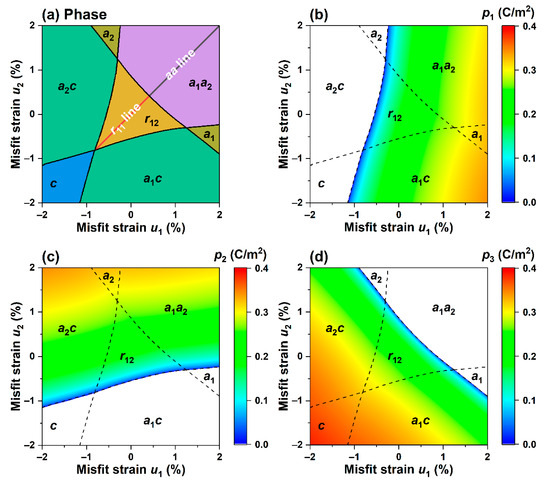
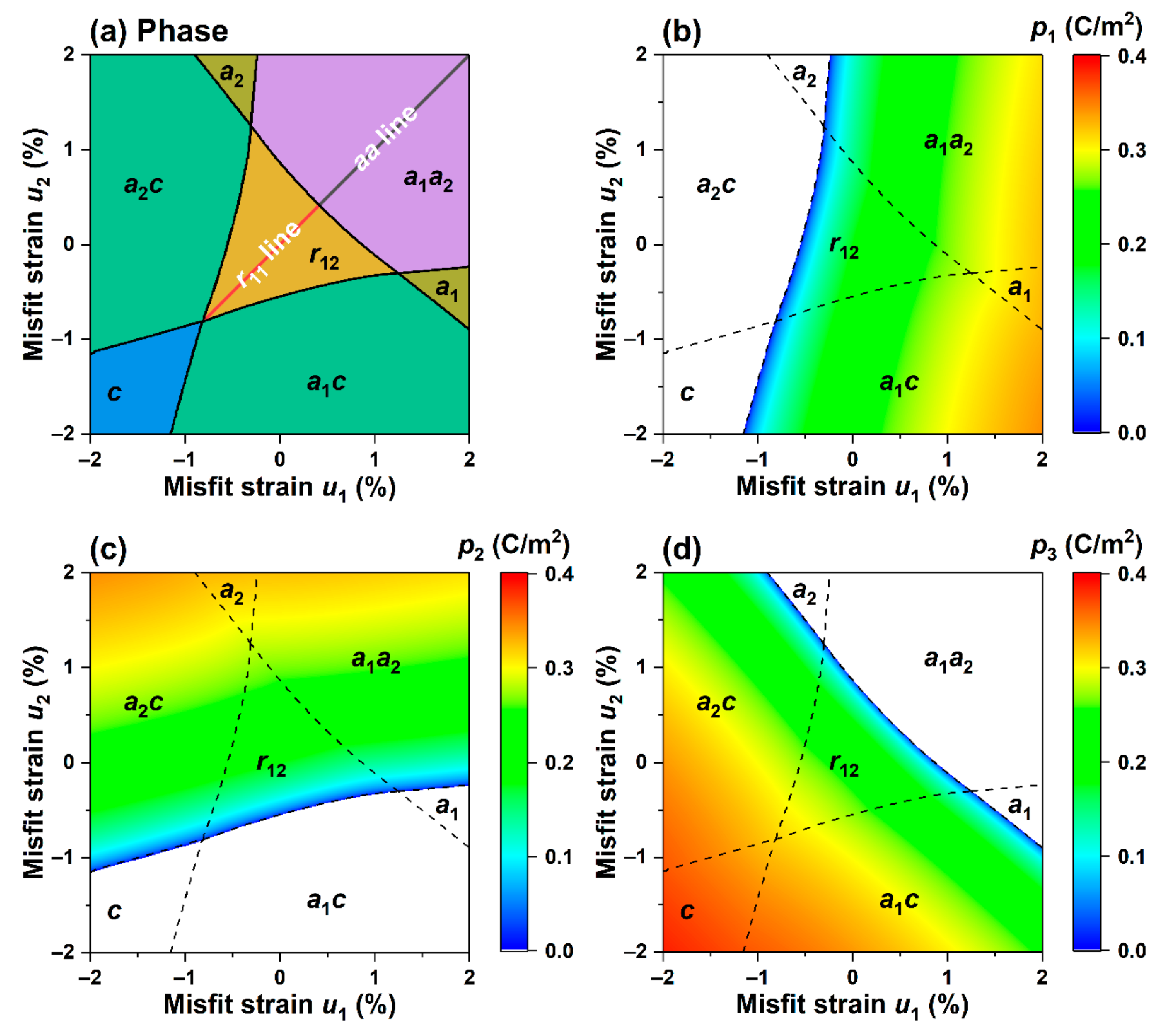
Figure 1.
(a) Non-isometric misfit strain-strain phase diagram for K0.5Na0.5NbO3 thin films at 25 °C without external electric field; (b–d) pseudo-color maps on strained phase diagrams depicting the polarization components respectively.
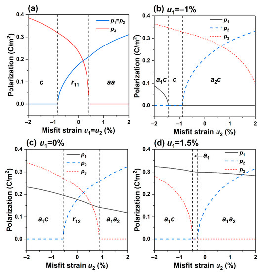
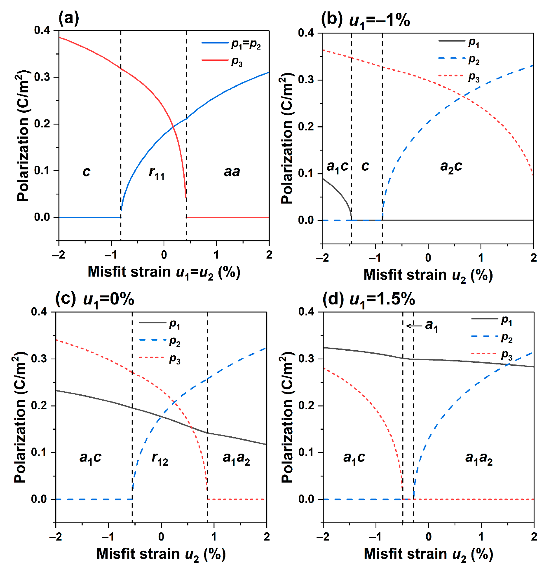
Figure 2.
(a) Strain-Polarization diagram with at 25 °C and subjected to no electric field. Strain -Polarization diagram with at 25 °C and subjected to no electric field: (b), (c), (d).
Interestingly, when and are not equal, which corresponds to in-plane non-equiaxed misfit strain, the symmetry of the phase structure of the K0.5Na0.5NbO3 thin film is obviously broken at room temperature, leading to the emergence of a rich variety of phase structures. There are seven phase structures according to the applied misfit strains, and the polarization characteristics of each phase are featured in Table 2. Among these phases, the monoclinic phase corresponds to the center of the phase diagram, and other phases are distributed around it. The pattern of the overall phase diagram is symmetric about the line . The tetragonal phase exists in the region subjected to larger compressive in-plane strain. It can be seen from Figure 1b that in the transition from compressive strain to tensile strain, the plane polarization component gradually decreases to zero, making the phase disappear.
Table 2.
Phase structures and characteristic polarization components of K0.5Na0.5NbO3 thin films at room temperature and under no electric field.
At the same time, induces leading to unequal energies of the two phases and . The phase is more likely to form in the region with , while phase is more likely to form in the region . At the same time, the tetragonal phase is located in the region in the phase diagram with a large tensile normal strain , while the phase exists in the region with a large tensile normal strain . The phase is located in the region with large tensile normal strains and .
From the diagram showing polarization components, it can be seen that the non-equiaxed in-plane misfit strains and can affect the polarization of the film at room temperature. Figure 1b indicates that the in-plane polarization increases with the increase in the tensile strain . Figure 1c indicates that the change in direction of polarization is parallel to the strain and becomes larger as it increases. In contrast, Figure 1d shows that the out-of-plane polarization exists stably in the region with compressive strain and increases with the increase in compressive strains and .
Next, we observe the change of the polarization components with the misfit strains where the conditions with room temperature and no applied electric field are imposed. Figure 2b–d depict the relationships between polarization components and strains at , , and , respectively.
It is found that in Figure 2b, at , as the misfit strain increases from compressive strain to tensile strain (−2~2%), the film undergoes a sequence of phase transitions , and the orthorhombic phase accounts for the majority of which the polarization components and experience a sudden change in the phase. In contrast, the polarization component decreases continuously with the increase in strain. Figure 2c shows that the tetragonal phase degenerates while the monoclinic phase emerges, and the strain of phase boundary extends to −0.55%. As the strain becomes tensile and as the misfit strain increases, the thin films undergo a sequence of phase transformations , and the polarization component has no noticeable change. Still, the abrupt change point of the polarization component has dropped to the region with compressive strain. Figure 1 and Figure 2 illustrate that, compared with the equiaxed misfit strain, the non-equiaxed misfit strain causes a change in the symmetry of the phase structure, thus inducing a rich variety of phase structures. Moreover, multiple phases co-exist near the phase boundary, leading to easy polarization, enhancing the performance, and effectively controlling the electromechanical properties of K0.5Na0.5NbO3 epitaxial film.
To explore the influence of non-equiaxed misfit strain on the electromechanical properties of K0.5Na0.5NbO3 epitaxial film, we calculated the dielectric constant
and piezoelectric coefficient of K0.5Na0.5NbO3 epitaxial film under non-equiaxed misfit strain, as shown in Figure 3, Figure 4, Figure 5 and Figure 6.
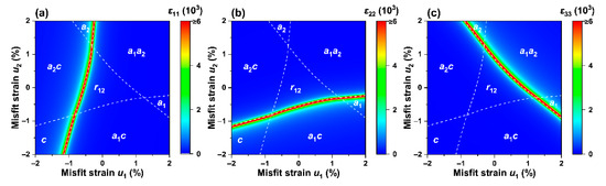
Figure 3.
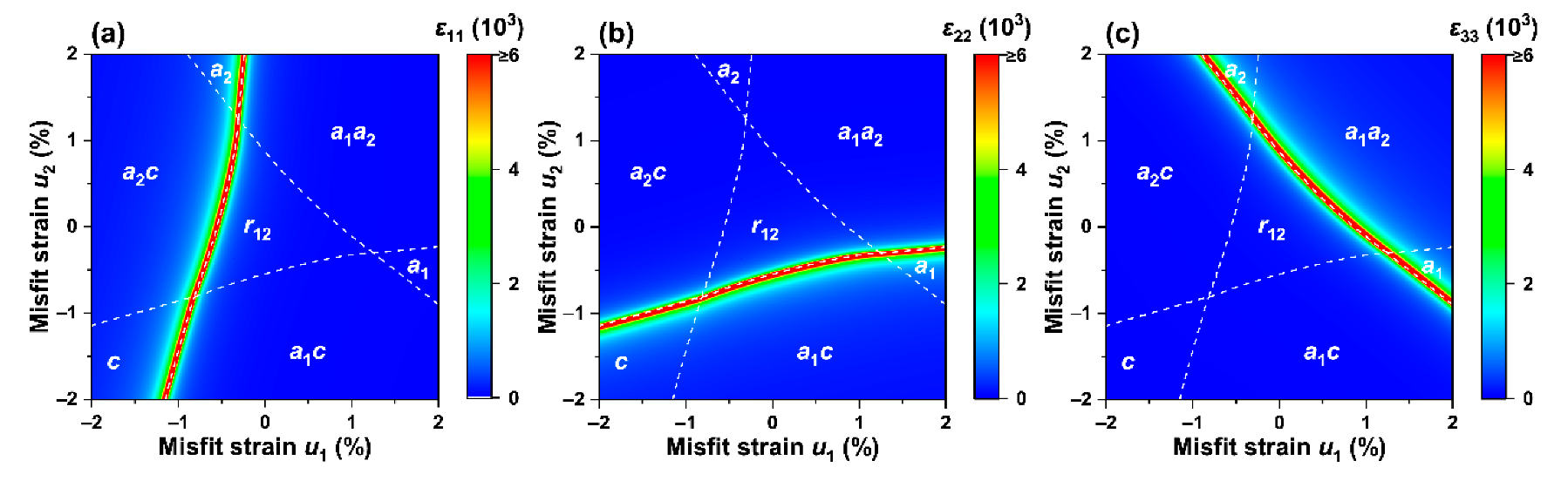
The permittivity (a) , (b) , and (c) on strain–strain phase diagram at 25 °C and subjected to an electric field of 0 MV/m.
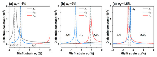
Figure 4.
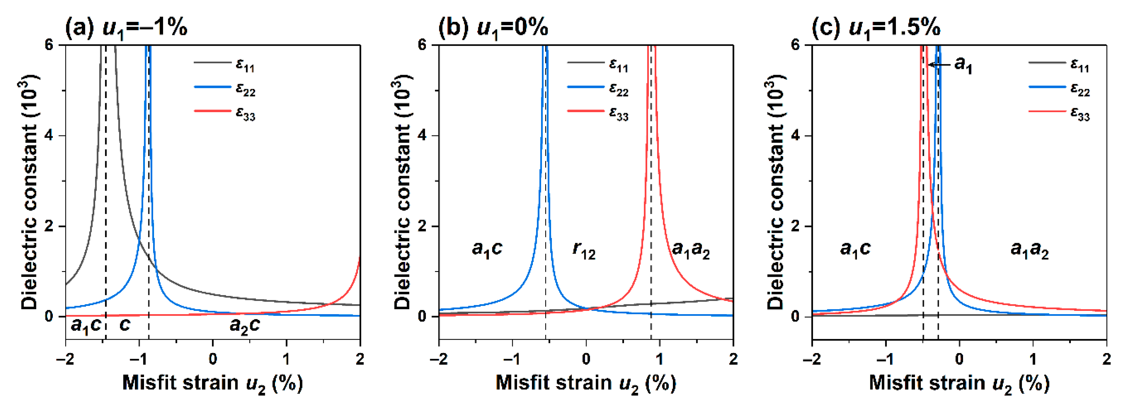
Dielectric constants as a function of in-plane strain at 25 °C with an electric field of 0 MV/m): (a) ; (b) ; (c) .
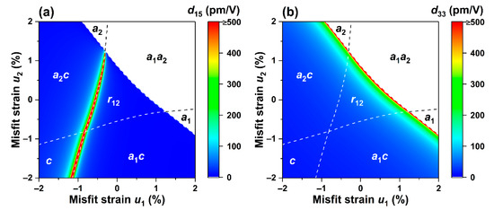
Figure 5.
Pseudo-color maps of piezoelectric coefficients on strained phase diagrams at 25 °C subjected to no electric field (0 MV/m): (a) , (b) .
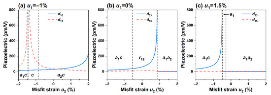
Figure 6.
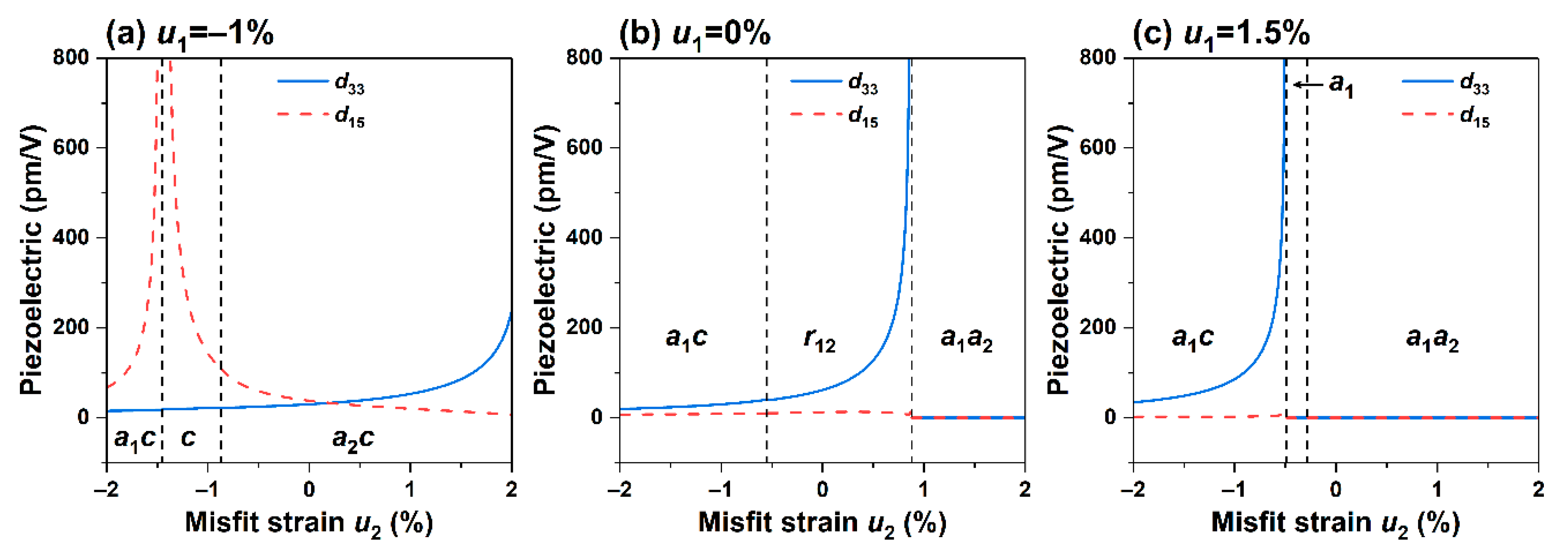
Relation between piezoelectric coefficients and in-plane strain at 25 °C and subjected to no electric field (0 MV/m) for (a) ; (b) ; (c) .
Figure 3a–c show the stack distribution of the dielectric constants on the phase diagram when the non-equiaxed misfit strains () interact at room temperature. Figure 3a demonstrates that near the phase boundaries exhibit excellent transverse permittivity , mainly due to the polarization component gradually decreasing to 0 as the strain decreases, as shown in Figure 1b. In Figure 3b, the scores of permittivity are mainly distributed near the multi-phase boundaries , in the range of low compressive strain . In the region of Figure 3c with a larger tensile strain , application of induces large , indicating that non-equiaxed misfit strain enhances the dielectric constant near the phase boundaries with the coexistence of multi-phase at room temperature, which is consistent with the discovery in the KNN-based thin film by Lou et al. [52] where a monoclinic phase emerges at room temperature with a noticeable performance enhancement near the phase boundary.
To further understand the influence of non-equiaxed strains on the dielectric properties, we selected the region of the phase diagram with high dielectric properties to study the relationship between specific strain and polarization characteristics and electromechanical properties, as shown in Figure 4a–c. Figure 4a shows the relationship between the dielectric constant and the in-plane strain , when . Recall that the relationship between the corresponding polarization and the phase structure has been described in Figure 2b. In the figure, it can be seen that with the increase in strain , the dielectric constant increases slowly, and there is no apparent change near the phase boundary, mainly because the out-of-plane polarization component of the film remains relatively stable when the strain is applied. However, in the region of the phase diagram corresponding to the coexistence of the orthogonal and tetragonal phases, the lateral permittivity and exhibit peak values when the applied strains are and , respectively. A stable region with a permittivity of about 500 is also observed in the phase.
For the case with , when the applied electric field is 0, at 25 °C, the phase diagram corresponding to its polarization component is shown in Figure 2c. A sharp peak in the permittivity appears near the phase boundary, which can be seen as the abrupt change in the polarization component from Figure 1c. In addition, at this phase transition point, the in-plane polarization gradually decreases to 0, and its slope changes discontinuously. At the same time, the dielectric constant is located at the point where the slope of the out-of-plane polarization decreases, and due to the slight decrease in the in-plane polarization , the dielectric constant remains basically unchanged. It can maintain good stability at room temperature, and the peak value of throughout the process is greater than .
We also calculated the relationship between the dielectric constant and strain, as shown in Figure 4c, when the tensile strain is . Similar to Figure 4b, a phase enhancement effect is also observed. The peaks of and are located at the orthogonal and tetragonal phase boundaries. The strain difference between these peaks is small due to the sudden change in the corresponding polarization component, where the discontinuity of is shifted towards the direction of compressive strain.
Next, we studied the influences of non-equiaxed misfit strain on the piezoelectric coefficients and of the K0.5Na0.5NbO3 epitaxial film. Figure 5a,b show the cloud distributions of the piezoelectric coefficients and when the applied electric field is 0 at room temperature. It can be found that the piezoelectric coefficients are all zero across the phase structures ,, and . This is mainly attributed to the distribution of polarization components in Figure 1d, which is consistent with the piezoelectric coefficients only when the asymmetric structure is met.
The distribution of the extreme value of the piezoelectric coefficient is similar to that of the dielectric constant , which exists at the phase boundaries of and phases. The distribution of the piezoelectric coefficient is similar to the dielectric constant and follows a similar trend, which undergoes enhancement when the polarization component experiences a sudden change. While it is most well known in the PZT film, which has tetragonal and rhombohedral phases coexisting at MPB, there is a certain difference in the mechanism of the two. MPB is due to the polarization reversal generated by the material itself, which causes the enhancement effect, and the polarization component will change discontinuously near the phase boundary. For the KNN film, it is regulated by external strain.
In Figure 6a, when , the relationship between the piezoelectric coefficient and the misfit strain , when it is changed from compressive strain to tensile strain, the phase structure undergoes a transformation: . It is found that the piezoelectric coefficient attains a peak value near the phase boundary, and the strain is mainly caused by the sharp change in the slope of in-plane polarization . is rising continuously. Along the diagonal region of the phase diagram, the influence of the phase boundary on the electromechanical performance is minimal because the polarization components at the phase transition point are all continuously changing with no sudden change in the slope.
Figure 6b, c show the relationship curves of the piezoelectric coefficient and strain when the misfit strain is 0 and 1.5%, respectively. It can be seen the piezoelectric coefficient is close to 0 with no noticeable change in the polarization in the phase diagram where the polarization component is in a stable state. When the misfit strain is not present, the piezoelectric coefficient attains peak values near the phase boundary, while away from the peak, it changes slowly in the orthorhombic phase. When subjected to tensile strain , the piezoelectric coefficient peaks at , which is similar to the trend of the dielectric constant because its value is the product of the polarization component and the dielectric constant.
In general, the enhancement of electromechanical properties often occurs near the O-M, O-T, and T-M phase boundaries, which is consistent with the existence of morphotropic phase boundaries in the KNN system and is regulated by external strain. At the same time, when the in-plane polarization changes suddenly, the dielectric constants and piezoelectric coefficient attain peak values, and when the in-plane polarization changes, the dielectric constants follow the change. When the dielectric constants and piezoelectric coefficient are at peaks, the slope of the out-of-plane polarization often changes abruptly. When the value of is 0, the piezoelectric coefficients and are both zero. By adjusting the magnitude of the misfit strain, the position of the polymorphic phase boundary at room temperature can be controlled, thereby adjusting the electromechanical properties of the thin film system.
Finally, we studied the effect of non-equiaxed misfit strains on the adiabatic temperature change in the electrocaloric response of K0.5Na0.5NbO3 thin film. At room temperature, an electric field change of 20 MV/m along the [001] direction is applied from an initial electric field of 1 MV/m. Figure 7a shows that at room temperature, the phase boundaries , , and shift towards tensile strain compared to the case with no applied electric field (as indicated by the white dashed line versus phase boundary enhancement), which is due to the applied electric field along the direction of the out-of-plane polarization , leading to enhancement. At the same time, large adiabatic temperature changes appear near the , , and phase boundaries because the polarization near these phase boundaries is zero when there is no external electric field, when compared (cross-referenced) to Figure 1d; when an external electric field in the [001] direction is applied, increases, causing a large entropy change, resulting in a large adiabatic temperature change .
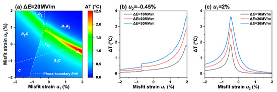
Figure 7.
(a) Adiabatic temperature change on the strain phase diagram (red line) at 25 °C and electric field of MV/m. Adiabatic temperature diagrams when the electric field is applied at 10, 20, 30 MV/m for in-plane misfit strain of (b) –0.45%; (c) 2%.
There is a difference in the extreme value of the adiabatic temperature change near the ferroelectric phase, indicating that the enhancement is not caused by the Curie temperature of the ferroelectric material. When the strain remains constant, the enhancement of phase boundaries in Figure 7a shows an upward trend with the increase in the in-plane strain , possibly due to the continuous decrease in polarization under this condition. To further understand the electrocaloric effect under the applied electric field and the in-plane misfit, we calculated the characteristics of the adiabatic temperature change with the misfit strain under different applied electric fields when and were 2% and −0.45%, respectively, as shown in Figure 7b, c. The study found that with the increase of the applied electric field, increases and remains unchanged upon reaching the peak value. In Figure 7b, as increases, the adiabatic temperature change shows an upward trend. When is about −0.7%, experiences a small mutation, which is caused by the emergence of the polarization component . In Figure 7c, the adiabatic temperature change can reach 3.62 K subjected to , which is further improved compared to the equiaxed misfit strain. The peak of is clearly seen at the phase transition in Figure 7c, indicating that an appropriate non-equiaxed misfit strain and an applied electric field can enhance the electrocaloric effect at room temperature. This provides a specific guiding significance for the stable operation of the electrocaloric refrigeration device at room temperature.
4. Conclusions
In summary, this article uses the nonlinear Landau-Devonshire thermodynamic theory to study the effects of non-equiaxed in-plane misfit strains on the phase structures, electromechanical properties, and electrocaloric effect of K0.5Na0.5NbO3 epitaxial thin films grown on anisotropic substrates at room temperature. It is found that at room temperature, misfit strain can induce orthorhombic phases (), tetragonal phases (), and monoclinic phases (). Due to the sudden change in the slope of the in-plane and out-of-plane polarization components, the electromechanical properties and electrocaloric effects are enhanced near the O-M, T-M, and O-T phase boundaries. The phase boundary generated by strain engineering is different from MPB in classical PZT. Among these phase structures, there are excellent dielectric constant and piezoelectric coefficient near the phase boundary. At the same time, the applied electric field along the [001] direction can shift the phase boundary in the direction of strain increase. When the electric field changes to 30 MV/m, the adiabatic temperature change can reach about 3.6 K when the film is in the monoclinic phase . This work provides theoretical guidance for experimental research on controlling lead-free K1−xNaxNbO3 thin films by strain engineering.
Author Contributions
Y.W.: analysis of the data and review. Y.O.: conceptualization, theoretical calculations, and writing the original draft. J.P.: review, editing, and interpretation of the analyzed data. C.L.: analysis of data, review, and editing. All authors have read and agreed to the published version of the manuscript.
Funding
This work was partially supported by the National Natural Science Foundation of China (11702092), and the project was supported by the Hunan Provincial Natural Science Foundation of China (2020JJ5182). C. H. Lei acknowledges the support from the Department of Aerospace and Mechanical Engineering at Saint Louis University.
Institutional Review Board Statement
Not applicable.
Informed Consent Statement
Not applicable.
Data Availability Statement
Not applicable.
Conflicts of Interest
The authors declare no conflict of interest.
References
- Liu, Y.; Seidel, J.; Li, J. Multiferroics under the Tip: Probing Magnetoelectric Coupling at the Nanoscale. Natl. Sci. Rev. 2019, 6, 626–628. [Google Scholar] [CrossRef]
- Jiang, P.; Huang, B.; Wei, L.; Yan, F.; Huang, X.; Li, Y.; Xie, S.; Pan, K.; Liu, Y.; Li, J. Resolving Fine Electromechanical Structure of Collagen Fibrils via Sequential Excitation Piezoresponse Force Microscopy. Nanotechnology 2019, 30, 205703. [Google Scholar] [CrossRef] [PubMed]
- Martin, L.; Rappe, A. Thin-Film Ferroelectric Materials and Their Applications. Nat. Rev. Mater. 2016, 2, 16087. [Google Scholar] [CrossRef]
- Liu, Y.; Li, J. Multiferroics: Looking Back and Going Forward. Sci. China Technol. Sci. 2020, 63, 2735–2736. [Google Scholar] [CrossRef]
- Nouchokgwe, Y.; Lheritier, P.; Hong, C.; Torelló, A.; Faye, R.; Jo, W.; Bahl, C.R.H.; Defay, E. Giant Electrocaloric Materials Energy Efficiency in Highly Ordered Lead Scandium Tantalate. Nat. Commun. 2021, 12, 3298. [Google Scholar] [CrossRef]
- Shi, J.; Han, D.; Li, Z.; Yang, L.; Lu, S.; Zhong, Z.; Chen, J.; Zhang, Q.; Qian, X. Electrocaloric Cooling Materials and Devices for Zero-Global-Warming-Potential, High-Efficiency Refrigeration. Joule 2019, 3, 1200–1225. [Google Scholar] [CrossRef]
- Chen, X.; Xu, S.; Yao, N.; Shi, Y. 1.6 V Nanogenerator for Mechanical Energy Harvesting Using PZT Nanofibers. Nano Lett. 2010, 10, 2133–2137. [Google Scholar] [CrossRef]
- Zhu, Q.; Pan, K.; Xie, S.; Liu, Y.; Li, J. Nanomechanics of Multiferroic Composite Nanofibers via Local Excitation Piezoresponse Force Microscopy. J. Mech. Phys. Solids 2019, 126, 76–86. [Google Scholar] [CrossRef]
- Carl, K.; Härdtl, K. On the Origin of the Maximum in the Electromechanical Activity in Pb(ZrxTi1−x)O3 Ceramies near the Morphotropic Phase Boundary. Phys. Status Solidi (a) 1971, 8, 87–98. [Google Scholar] [CrossRef]
- Auciello, O.; Gifford, K.; Lichtenwalner, D.; Dat, R.; Al-Shareef, H.; Bellur, K.; Kincon, A.I. A Review of Composition-Structure-Property Relationships for PZT-Based Heterostructure Capacitors. Integr. Ferroelectr. 1995, 6, 173–187. [Google Scholar] [CrossRef]
- Pandey, D.; Singh, A.; Baik, S. Stability of Ferroic Phases in the Highly Piezoelectric Pb(ZrxTi1−x)O3 Ceramics. Acta Crystallogr. A Found Crystallogr 2008, 64, 192–203. [Google Scholar] [CrossRef]
- Mischenko, A.; Zhang, Q.; Scott, J.; Whatmore, R.; Mathur, N. Giant Electrocaloric Effect in Thin-Film PbZr0.95Ti0.05O3. Science 2006, 311, 1270–1271. [Google Scholar] [CrossRef]
- Li, J.; Wang, K.; Zhu, F.; Cheng, L.; Yao, F. (K,Na)NbO3-Based Lead-Free Piezoceramics: Fundamental Aspects, Processing Technologies, and Remaining Challenges. J. Am. Ceram. Soc. 2013, 96, 3677–3696. [Google Scholar] [CrossRef]
- McFarland, M.; Hauer, M.; Reuben, A. Half of US Population Exposed to Adverse Lead Levels in Early Childhood. Proc. Natl. Acad. Sci. USA 2022, 119, e2118631119. [Google Scholar] [CrossRef]
- Saito, Y.; Takao, H.; Tani, T.; Nonoyama, K.; Takatori, K.; Homma, T.; Nagaya, T.; Nakamurra, M. Lead-free piezoceramics. Nature 2002, 432, 84–87. [Google Scholar] [CrossRef] [PubMed]
- Wang, K.; Malič, B.; Wu, J. Shifting the Phase Boundary: Potassium Sodium Niobate Derivates. MRS Bull. 2018, 43, 607–611. [Google Scholar] [CrossRef]
- Wu, J.; Xiao, D.; Zhu, J. Potassium–Sodium Niobate Lead-Free Piezoelectric Materials: Past, Present, and Future of Phase Boundaries. Chem. Rev. 2015, 115, 2559–2595. [Google Scholar] [CrossRef] [PubMed]
- Koruza, J.; Rožič, B.; Cordoyiannis, G.; Malič, B.; Kutnjak, Z. Large Electrocaloric Effect in Lead-Free K0.5Na0.5NbO3-SrTiO3 Ceramics. Appl. Phys. Lett. 2015, 106, 202905. [Google Scholar] [CrossRef]
- Wang, Z.; Gu, H.; Hu, Y.; Yang, K.; Hu, M.; Zhou, D.; Guan, J. Synthesis, Growth Mechanism and Optical Properties of (K,Na)NbO3 Nanostructures. CrystEngComm 2010, 12, 3157. [Google Scholar] [CrossRef]
- Meng, X.; Wang, W.; Ke, H.; Rao, J.; Jia, D.; Zhou, Y. Synthesis, Piezoelectric Property and Domain Behaviour of the Vertically Aligned K1−xNaxNbO3 Nanowire with a Morphotropic Phase Boundary. J. Mater. Chem. C 2017, 5, 747–753. [Google Scholar] [CrossRef]
- Jin, W.; Wang, Z.; Li, M.; He, Y.; Hu, X.; Li, L.; Gao, Y.; Hu, Y.; Gu, H.; Wang, X. Evolution of the Composition, Structure, and Piezoelectric Performance of (K1-xNax)NbO3 Nanorod Arrays with Hydrothermal Reaction Time. Appl. Phys. Lett. 2018, 112, 142904. [Google Scholar] [CrossRef]
- Esin, A.; Alikin, D.; Turygin, A.; Abramov, A.; Hreščak, J.; Walker, J.; Rojac, T.; Bencan, A.; Malic, B.; Kholkin, A.; et al. Dielectric Relaxation and Charged Domain Walls in (K,Na)NbO3-Based Ferroelectric Ceramics. J. Appl. Phys. 2017, 121, 074101. [Google Scholar] [CrossRef]
- Wang, X.; Wu, J.; Xiao, D.; Zhu, J.; Cheng, X.; Zheng, T.; Zhang, B.; Lou, X.; Wang, X. Giant Piezoelectricity in Potassium–Sodium Niobate Lead-Free Ceramics. J. Am. Chem. Soc. 2014, 136, 2905–2910. [Google Scholar] [CrossRef] [PubMed]
- Ge, W.; Li, J.; Viehland, D.; Chang, Y.; Messing, G. Electric-Field-Dependent Phase Volume Fractions and Enhanced Piezoelectricity near the Polymorphic Phase Boundary of (K0.5Na0.5)1−xLixNbO3 Textured Ceramics. Phys. Rev. B 2011, 83, 224110. [Google Scholar] [CrossRef]
- Tan, Z.; Xing, J.; Peng, Y.; Zhang, Q.; Zhu, J. Polarization Rotation Boosts Strong Piezoelectric Response in the Lead-Free Perovskite Ferroelectric K0.5Na0.5NbO3. Phys. Rev. B 2021, 104, 014104. [Google Scholar] [CrossRef]
- Seog, H.; Ullah, A.; Ahn, C.; Kim, I.; Lee, S.; Park, J.; Lee, H.; Won, S.; Kim, S. Recent Progress in Potassium Sodium Niobate Lead-Free Thin Films. J. Korean Phys. Soc. 2018, 72, 1467–1483. [Google Scholar] [CrossRef]
- von Helden, L.; Bogula, L.; Janolin, P.; Hanke, M.; Breuer, T.; Schmidbauer, M.; Ganschow, S.; Schwarzkopf, J. Huge Impact of Compressive Strain on Phase Transition Temperatures in Epitaxial Ferroelectric KxNa1−xNbO3 Thin Films. Appl. Phys. Lett. 2019, 114, 232905. [Google Scholar] [CrossRef]
- Shan, D.; Lei, C.; Cai, Y.; Pan, K.; Liu, Y. Mechanical Control of Electrocaloric Response in Epitaxial Ferroelectric Thin Films. Int. J. Solids Struct. 2021, 216, 59–67. [Google Scholar] [CrossRef]
- Liu, Y.; Vasudevan, R.; Pan, K.; Xie, S.; Liang, W.; Kumar, A.; Jesse, S.; Chen, Y.-C.; Chu, Y.-H.; Nagarajan, V.; et al. Controlling Magnetoelectric Coupling by Nanoscale Phase Transformation in Strain Engineered Bismuth Ferrite. Nanoscale 2012, 4, 3175. [Google Scholar] [CrossRef]
- Hu, S.; Li, Y.; Chen, L. Effect of Interfacial Dislocations on Ferroelectric Phase Stability and Domain Morphology in a Thin Film—A Phase-Field Model. J. Appl. Phys. 2003, 94, 2542–2547. [Google Scholar] [CrossRef]
- Zhuo, F.; Zhou, X.; Gao, S.; Dietrich, F.; Groszewicz, P.; Fulanović, L.; Breckner, P.; Xu, B.; Kleebe, H.; Damjanovic, D.; et al. Intrinsic-Strain Engineering by Dislocation Imprint in Bulk Ferroelectrics. Phys. Rev. Lett. 2023, 131, 016801. [Google Scholar] [CrossRef]
- Sang, Y.; Liu, B.; Fang, D. The Size and Strain Effects on the Electric-Field-Induced Domain Evolution and Hysteresis Loop in Ferroelectric BaTiO3 Nanofilms. Comput. Mater. Sci. 2008, 44, 404–410. [Google Scholar] [CrossRef]
- Wang, J.; Su, Y.; Wang, B.; Ouyang, J.; Ren, Y.; Chen, L. Strain Engineering of Dischargeable Energy Density of Ferroelectric Thin-Film Capacitors. Nano Energy 2020, 72, 104665. [Google Scholar] [CrossRef]
- Liu, D.; Bai, G.; Gao, C. Phase Diagrams Classification Based on Machine Learning and Phenomenological Investigation of Physical Properties in K1−xNaxNbO3 Thin Films. J. Appl. Phys. 2020, 127, 154101. [Google Scholar] [CrossRef]
- Zhou, M.; Wang, J.; Chen, L.; Nan, C. Strain, Temperature, and Electric-Field Effects on the Phase Transition and Piezoelectric Responses of K 0.5 Na 0.5 NbO 3 Thin Films. J. Appl. Phys. 2018, 123, 154106. [Google Scholar] [CrossRef]
- Pohlmann, H.; Wang, J.; Wang, B.; Chen, L. A Thermodynamic Potential and the Temperature-Composition Phase Diagram for Single-Crystalline K1-xNaxNbO3 (0 ≤ x ≤ 0.5). Appl. Phys. Lett. 2017, 110, 102906. [Google Scholar] [CrossRef]
- Peng, J.; Shan, D.; Liu, Y.; Pan, K.; Lei, C.; He, N.; Zhang, Z.; Yang, Q. A Thermodynamic Potential for Barium Zirconate Titanate Solid Solutions. npj Comput. Mater. 2018, 4, 66. [Google Scholar] [CrossRef]
- Liu, Y.; Zhu, Z.; Li, J.; Li, J. Misfit Strain Modulated Phase Structures of Epitaxial Pb(Zr1−xTix)O3 Thin Films: The Effect of Substrate and Film Thickness. Mech. Mater. 2010, 42, 816–826. [Google Scholar] [CrossRef]
- Pertsev, N.; Zembilgotov, A.; Tagantsev, A. Effect of Mechanical Boundary Conditions on Phase Diagrams of Epitaxial Ferroelectric Thin Films. Phys. Rev. Lett. 1998, 80, 1988–1991. [Google Scholar] [CrossRef]
- Liu, Y.; Li, J. Shear-Driven Morphotropic Phase Boundary in Epitaxial Ferroelectric Thin Films. Phys. Rev. B 2011, 84, 132104. [Google Scholar] [CrossRef]
- Haun, M.; Furman, E.; Jang, S.; Cross, L. Thermodynamic Theory of the Lead Zirconate-Titanate Solid Solution System, Part I: Phenomenology. Ferroelectrics 1989, 99, 13–25. [Google Scholar] [CrossRef]
- Liu, Y.; Yang, L.; Li, J. Strain-Engineered Orthorhombic-Rhombohedral Phase Boundary in Epitaxial Bismuth Ferrite Films. J. Appl. Phys. 2013, 113, 183524. [Google Scholar] [CrossRef]
- Pertsev, N.; Kukhar, V.; Kohlstedt, H.; Waser, R. Phase Diagrams and Physical Properties of Single-Domain Epitaxial Pb(Zr1-xTix)O3 Thin Films. Phys. Rev. B 2003, 67, 054107. [Google Scholar] [CrossRef]
- Tomeno, I.; Tsunoda, Y.; Oka, K.; Matsuura, M.; Nishi, M. Lattice Dynamics of Cubic NaNbO3: An Inelastic Neutron Scattering Study. Phys. Rev. B 2009, 80, 104101. [Google Scholar] [CrossRef]
- Liang, L.; Li, Y.; Chen, L.; Hu, S.; Lu, G. A Thermodynamic Free Energy Function for Potassium Niobate. Appl. Phys. Lett. 2009, 94, 072904. [Google Scholar] [CrossRef]
- Barman, A.; Kar-Narayan, S.; Mukherjee, D. Caloric Effects in Perovskite Oxides. Adv. Mater. Interfaces 2019, 6, 1900291. [Google Scholar] [CrossRef]
- Shan, D.; Pan, K.; Liu, Y.; Li, J. High Fidelity Direct Measurement of Local Electrocaloric Effect by Scanning Thermal Microscopy. Nano Energy 2020, 67, 104203. [Google Scholar] [CrossRef]
- Pirc, R.; Kutnjak, Z.; Blinc, R.; Zhang, Q. Electrocaloric Effect in Relaxor Ferroelectrics. J. Appl. Phys. 2011, 110, 074113. [Google Scholar] [CrossRef]
- He, N.; Li, Q.; Lei, C.; Pan, J.; Shan, D.; Pan, K.; Liu, Y. Electrocaloric Response Modulated by Misfit Strain in Different Oriented Epitaxial Ferroelectric Thin Films. Int. J. Solids Struct. 2022, 252, 111808. [Google Scholar] [CrossRef]
- Shan, D.; Cai, Y.; Lei, C.; Peng, J.; He, N.; Pan, K.; Liu, Y.; Li, J. Electric-Field-Driven Coexistence of Positive and Negative Electrocaloric Effects near Room Temperature for High-Efficiency Two-Stage Cooling. Appl. Phys. Lett. 2021, 118, 122905. [Google Scholar] [CrossRef]
- Lei, C.; Liu, Y. Correlations between Local Electrocaloric Effect and Domains in Ferroelectric Crystals. Appl. Phys. Lett. 2022, 121, 102902. [Google Scholar] [CrossRef]
- Luo, J.; Sun, W.; Zhou, Z.; Lee, H.; Wang, K.; Zhu, F.; Bai, Y.; Wang, Z.; Li, J. Monoclinic (K,Na)NbO3 Ferroelectric Phase in Epitaxial Films. Adv. Electron. Mater. 2017, 3, 1700226. [Google Scholar] [CrossRef]


Disclaimer/Publisher’s Note: The statements, opinions and data contained in all publications are solely those of the individual author(s) and contributor(s) and not of MDPI and/or the editor(s). MDPI and/or the editor(s) disclaim responsibility for any injury to people or property resulting from any ideas, methods, instructions or products referred to in the content. |
© 2023 by the authors. Licensee MDPI, Basel, Switzerland. This article is an open access article distributed under the terms and conditions of the Creative Commons Attribution (CC BY) license (https://creativecommons.org/licenses/by/4.0/).